





Abstract
Flow pumps act as important devices in areas such as Bioengineering, Medicine, and Pharmacy, among other areas of Engineering, mainly for delivering liquids or gases at small-scale and precision flow rate quantities. Principles for pumping fluids based on piezoelectric actuators have been widely studied, since they allow the construction of pump systems for displacement of small fluid volumes with low power consumption. This work studies valveless piezoelectric diaphragm pumps for flow generation, which uses a piezoelectric ceramic (PZT) as actuator to move a membrane (diaphragm) up and down as a piston. The direction of the flow is guaranteed by valveless configuration based on a nozzle–diffuser system that privileges the flow in just one pumping direction. Most research efforts on development of valveless flow pump deal either with computational simulations based on simplified models or with simplified physical approaches based on analytical models. The main objective of this work is the study of a methodology to develop a low-cost valveless piezoelectric diaphragm flow pump using computational simulations, parametric study, prototype manufacturing, and experimental characterization. The parametric study has shown that the eccentricity of PZT layer and metal layer plays a key role in the performance of the pump.
Introduction
Recently, piezoelectric ceramics (PZT) have been investigated as an interesting alternative for the construction of precision flow pumps, that is, small-size devices for pumping small fluid volumes (Laser and Santiago, 2004). These devices have lower noise generation, fewer numbers of moving parts, and provide low power consumption and, thus, it can be applied as an essential component of several pumping systems. The Bioengineering is an area that has demonstrated great interest for this type of equipment. In this area, these pumps can be used for continuous injection of insulin in diabetic patients during the day (Teymoori and Abbaspour-Sani, 2005), removing outbreaks and deficits of this substance, and for pumping of biological fluids (Andrade et al., 1996), for instance. Other possible application is for chemical reagents dosage in portable equipments utilized for clinical analyses (Tsai and Sue, 2007).
New principles of pumping fluids have been extensively proposed for piezoelectric flow pumps. For instance, one of them has pump configuration based on placing an oscillating bimorph piezoelectric actuator in a fluid channel to generate flow (Lima et al., 2009). This proposed principle of pumping mimics a phenomenon of the swimming fish (Sfakiotakis et al., 1999). Other principle consists of using piezoelectrically actuated structures (stators) to generate a propagating wave that moves the fluid (Bar-Cohen and Chang, 2001). The movement obtained in this flow pump is similar to the peristaltic movement, which is observed in the human esophagus.
Another field for application of piezoelectric flow pump is the cooling systems for electronic equipments, such as high-performance computers and notebooks. However, for this application, a pump system must provide a certain pressure due to high load loss in heat exchangers (Singhal et al., 2004). Nevertheless, it is possible to obtain larger pressures when a diaphragm pump is used. The first piezoelectric diaphragm pump, which has been presented by Lintel et al. (1988), uses diaphragm passive valves. It consists of an external flexible ring and of a rigid central ring. The active pressure in this kind of pump bends the external flexible ring and, then, it seals the internal ring.
Various designs of passive valves based on flaps or other moving structures have been proposed for diaphragm pumps, such as the valves in which a piezoelectric actuator known as ‘stack type’ is connected to the diaphragm (Esashi et al., 1989), and another that uses spheres to rectify the flow (Carrozza et al., 1995). A kind of diaphragm valve highly explored in the literature is known as ‘cantilever’ (Zengerle et al., 1995), which has a clamped beam structure that bends when subjected to pressure, allowing the flow.
In all these cited diaphragm pumps, the flow direction is guaranteed by passive valves (movable parts) that allow unidirectional flow. However, flow pumps with movable parts can have problems such as elevated pressure drop and fatigue. Besides, the resonance frequency of the passive valves must be near the resonance frequency of the actuator because it is necessary to obtain movement synchronization between the expansion and contraction of the diaphragm and the opening and closure of the valves; otherwise cavitation may occur. Moreover, it is difficult to construct these movable parts using conventional manufacturing processes, which turns flow pump cost very high.
Thus, piezoelectric diaphragm pumps based on the referred ‘no-moving-parts valves pumping systems’, in which valveless pump configurations are highlighted, have also been explored in the literature (Stemme and Stemme, 1993). A valveless pump consists of two fluid-flow rectifying diffuser/nozzle elements that are connected to the inlet and outlet of a pump chamber, which has a flexible diaphragm. Figure 1 illustrates a scheme of valveless flow pump (diaphragm pump). The main characteristic of a valveless flow pump is the channel geometry of nozzle–diffuser elements of fluid inlet and outlet of pump chamber, in a way that the pressure drop in the direction of the diffuser is less than the pressure drop in the direction of the nozzle, considering the same flow velocity for both directions. During the suction stroke, as the pump chamber volume increases (see Figure 1(a)), the inlet channel works as diffuser, allowing large amount of fluid entrance in the chamber, while the outlet channel (acting as nozzle) restrains strongly the fluid exit. On the other hand, during the discharge stroke, as the pump chamber decreases (Figure 1(b)), the outlet channel (acting as diffuser) allows large amount of fluid exit of the chamber, while the inlet channel works as nozzle, expelling a small reverse flow. The result of a complete pumping cycle is the net transport of fluid from the flow pump inlet to the outlet (Figure 1(c)), in spite of the nozzle–diffuser system allowing fluid flow in two directions.
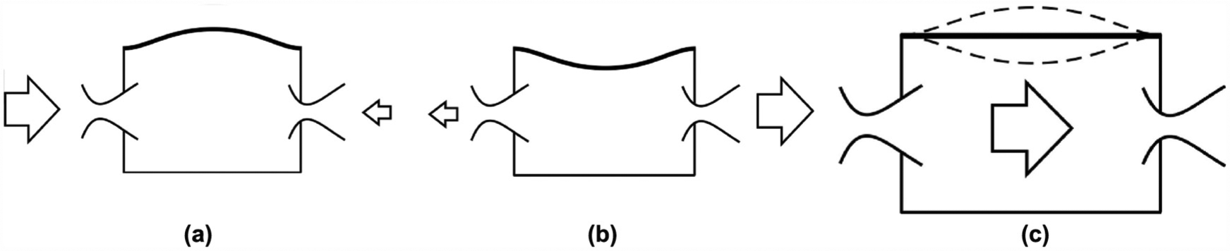
A valveless flow pump scheme: (a) suction stroke, (b) discharge stroke, and (c) one-directional flow.
Most research efforts on development of valveless flow pump deal either with numerical simulations based on simplified models (Gerlach and Wurmus, 1995; Jiankang and Lijun, 2006; Olsson et al., 1998; Ullmann and Fono, 2002) or with simplified analytical approaches (Amos, 1998; Li and Che, 2003; Stemme and Stemme, 1993; Ullmann, 1998). Nevertheless, as exact analytical solution for the valveless pump behavior is unfeasible, due to coupling effects, the finite element analysis (FEA) has become a useful method to model and predict the behavior of this device. Finite element method (FEM) is often utilized to optimize the geometric and material parameters of the valveless diaphragm pump (Li and Che, 2003; Morris and Forster, 2000). Nowadays, numerical simulations have been performed using practical Computational Fluid Dynamics (CFD) software. Cui et al. (2008) carried out a full coupled-field analysis, employing the ANSYS finite element software to evaluate the performance of a valveless micropump for medical applications, using a simplified 2D finite element (FE) model. Kim and Xu (2004) utilized a commercial CFD software (FLUENT) to analyze the performances of a nozzle–diffuser micropump; however, inlet and outlet chamber effects of their valveless micropump have not been included in the computational model. Karanth et al. (2010) used ANSYS software to develop a FEA model of a micropump, which applies a single or multilayer polymer piezoelectric film (PVDF) to an aluminum circular diaphragm for actuation. Yao et al. (2007) established full numerical PZT membrane micropump models and performed extensive CFD simulations; however, experimental validations have not been carried out. Olsson et al. (1996) built a CFD model using ANSYS/Flotran to analyze the flow-directing ability in valveless micropumps, considering only lengths and opening angles as design parameters for the nozzle/diffuser elements.
In this work, we propose a useful design methodology for the piezoelectric diaphragm pump based on low-cost computational FEA modeling as well as through experimental characterization of a manufactured prototype, constructed in mesoscale (millimeters). In addition, using FEA, the investigation of the diaphragm pump sensitivity in relation to some of its geometrical parameters (parametric analysis) is conducted.
The development design methodology for a low-cost diaphragm pump proposed in this work is presented in the following sections. The next section describes the fundamental theory, the ‘Computational Simulation’ section shows analysis of the proposed flow pump using computational simulations, and the ‘Experimen-tal Results’ section details the manufacturing and describes the experimental characterization and results achieved using a manufactured prototype. Finally, in the ‘Conclusion’ section, some discussion about obtained results and conclusion are given.
Fundamental Theory
The piezoelectric actuator (diaphragm) shown in Figure 2(a) is applied to flow pump analyzed in this work. This diaphragm is constructed using a PZT disk bonded to a metallic plate (cupper or brass) through a conductive epoxy sticker (glue layer). The PZT is capable of converting electric energy into mechanical energy and vice versa. When an electric voltage is applied to the piezoelectric disk terminals, the metallic plate (membrane) bends toward its perpendicular direction surface. As the contour of membrane is clamped (see Figure 2(b)), it presents a concave or convex deformation, which yields the pumping effect that generates fluid flow through the diaphragm pump. In this case, the PZT has a piston-like behavior, because when the diaphragm moves, reducing the pump chamber volume, the fluid is expelled from flow pump. Otherwise, when the diaphragm movement increases the pump chamber volume, the fluid enters the chamber.

(a) Piezoelectric diaphragm and (b) lateral view scheme of the diaphragm.
The piezoelectric actuator used in diaphragm flow pump in this work is an electromechanical device with high bending degree (Chee et al., 1998). This piezoelectric actuator (see Figure 2) is a low-cost product (about US$ 0.50) found easily in the market, and it can generate displacements less than 1 mm. The piezoelectric actuator is excited by harmonic or squared waves with frequencies around 100 Hz and maximum applied voltage around 340 V pp (peak-to-peak voltage), depending on the dimensions and geometry of the actuator.
Computational Simulation
Modeling Procedure
It is possible to calculate analytically the flow rate generated in a diaphragm pump through the difference between the expansion and contraction chamber volumes (Stemme and Larsson, 1973); however, a more detailed analytical formulation for the flow pump behavior could be very complex. Thus, in this work, the diaphragm flow pump is analyzed numerically through computational simulations using the FEM.
Using 3D models, computational simulations are carried out in two steps, as shown in Figure 3. In the first step, a computational model of the piezoelectric actuator (diaphragm) is created to provide, from harmonic analysis, resonance frequencies and vibration modes of the piezoelectric diaphragm surrounded by water. In addition, a parametric study is carried out to verify how construction parameters and assembly (described ahead) affect resonance frequencies and vibration amplitudes of the piezoelectric diaphragm. In the second step, considering the fluid–structure behavior in pump chamber, fluid-flow analysis (i.e., CFD analysis) of a diaphragm pump model (high-hierarchy model) is carried out using all compiled results obtained in the previous step.

Computational simulation steps.
Moreover, using a simplified model of the diaphragm pump, a sensitivity analysis is carried out for the geometrical parameters of nozzles/diffusers through low-time cost CFD analyses, based on amplitude and frequency data obtained in previous harmonic analysis (the first step shown in Figure 3). This sensitivity analysis aims to find optimum nozzle/diffuser geometries for maximizing flow rate and pressure output.
The constitutive equations that relate the electric and mechanical fields in piezoelectric media are given by (Ikeda, 1996):
where
Thus, in the piezoelectric actuator analyses, these coupled piezoelectric equations are solved numerically through the following FE formulation (Lerch, 1990):
where
In fluid-flow analysis, the FEM is applied to solve numerically the full Navier–Stokes equations for viscous incompressible fluid, described by the momentum and continuity equations as follows:
where
The ANSYS software is used for the piezoelectric diaphragm pump computational simulations, since its FE library (ANSYS, 2007) covers a wide range of physical phenomena as required in this work. To simulate the piezoelectric actuator in air, the SOLID98 element is used (harmonic analysis), which is capable of simulating both structural and piezoelectric effects. The actuator behavior inside pump chamber water medium is modeled using the FLUID30 element, which has displacement and pressure degrees of freedom, and it allows modeling of fluid–structure interaction. For simulating fluid medium behavior (fluid-flow analysis), the FLUID142 element is used. This element has velocity components, pressure, and temperature degrees of freedom, and it is capable of simulating laminar or turbulent flows in permanent or transient state (ANSYS, 2007).
Simulation Results
The adopted dimensions of the piezoelectric diaphragm model can be seen in Figure 4. The employed materials in this model are brass (metallic plate) and PZT-5A (piezoelectric disk). Brass properties used in simulations are Young’s modulus E = 97 GPa, Poisson’s ratio v = 0.34, and density ρbrass = 8530 Kg/m3. The PZT properties are described in Table 1. All dimension ranges for the parameters, adopted in this work, are selected based on manufacturing limitations and prototype design. That is, the construction of diaphragm pump prototypes using these dimension ranges is totally feasible and makes sense for the purpose of this work (small-size devices for pumping small fluid volumes).

Piezoelectric diaphragm model.
PZT-5A properties used in simulations.
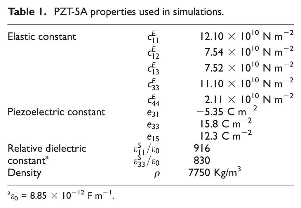
ϵ0 = 8.85 × 10⁻¹² F m−1.
First, harmonic analysis is carried out to obtain resonance frequencies and respective vibration modes of the piezoelectric actuator (diaphragm), considering water as fluid medium. These computational simulations show that the largest amplitude value is provided by the first symmetrical vibration mode of the piezoelectric actuator, which occurs at 45 Hz. Then, this first vibration mode is adopted in following simulations. Symmetrical vibration mode is dominant when circular piezoelectric actuators are excited electrically (Hong et al., 2006).
As damping property of the piezoelectric actuator disk is unknown a priori, a calibration procedure is necessary (Lima et al., 2009). A damping value must be estimated to allow for the calculation of vibration amplitudes (obtained through harmonic analysis) close to prototype diaphragm amplitude values, allowing comparison between computational and experimental results. In this case, an experimental measurement is performed to find the amplitude of the piezoelectric actuator displacement, using a MTI-2100 FOTONIC device, at resonance frequency inside water medium. A measured amplitude equal to 36 µm is found for applied voltage of 320 V pp and resonance frequency of 45 Hz. Then, computational simulations (harmonic analyses), which consider the actuator inside water medium, are carried out to find a damping property that generates the same measured amplitude value (36 µm) at 45 Hz. A damping property value equal to 0.000476 has been obtained, and this value is adopted to find the vibration amplitudes, considering other frequency values, for all 3D models presented in this work.
Parametric Study Conducted Using Harmonic Analyses
In the first step (see Figure 3), a parametric study is performed to verify the influence of following adopted geometrical parameters in diaphragm pump performance: length of the inlet and outlet pump fittings, nozzle/diffuser diameters, chamber height, and eccentricity in the assembly of piezoelectric actuator components. Thus, harmonic analyses are carried out using a 3D computational model, in which studied parameters are modified. Figure 5 illustrates the schematic drawing and FE mesh of the adopted computational model. The FE mesh has approximately 110,000 elements, and the boundary conditions are fixed contour in the chamber, nozzle/diffusers and tube, applied voltage (320 V
pp
) and null voltage (‘ground’) at the piezoelectric actuator electrodes, null pressure at inlet and outlet pumps, and longitudinal symmetry. Moreover, water medium properties (

Model adopted for carrying out parametric analysis: (a) schematic drawing and (b) FE mesh.
Considering some adopted values (5, 20, 50, and 80 mm), based on manufacturing constraints, for the length of inlet and outlet pump fittings (parameter cfit illustrated in Figure 5(a)), and also considering distinct computational models in which the chamber height (h) varies from 8 to 17 mm range, computational simulations show that these parameters do not affect significantly the resonance frequency and amplitude behavior of the piezoelectric actuator, which is found to be equal to 45 Hz and 36 µm (at first vibration mode), respectively. Thus, diaphragm pump performance is not sensitive to these adopted range parameters. This occurs because the amplitude of the actuator movement is much smaller than chamber height. As matter of fact, this conclusion has agreement with the analytical results reported by Ullmann and Fono (2002), considering the ranges simulated in this work, which validates the parametric study developed here.
Nevertheless, it is noticed that piezoelectric actuator behavior is significantly modified when eccentricity in assembly occurs. Figure 6 illustrates the eccentricity parameter (e). In this case, several assemblies considering eccentricity parameter values varying from 0 to 2 mm range are simulated.
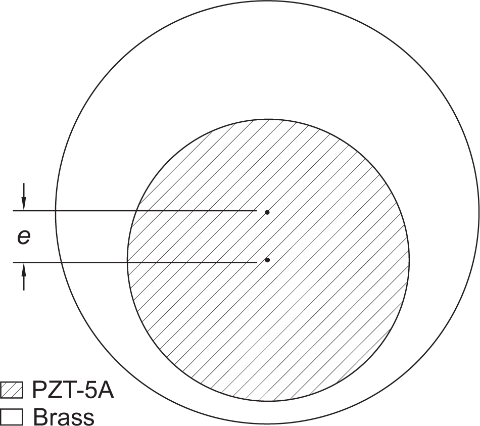
Eccentricity between piezoelectric disk and metallic plate.
Plots of Figure 7 show simulation results, where it is noticed that as eccentricity (e) is increased, the resonance frequency (at first vibration mode) increases, while amplitude of piezoelectric actuator decreases. In other words, a critical parameter for performance of piezoelectric diaphragm pump is eccentricity in the assembly of piezoelectric actuator components. Eccentricity can occur due to deviation in bonding between the PZT disk and the metallic plate or due to pump assembly.

Eccentricity parameter variation: (a) eccentricity versus frequency curve and (b) eccentricity versus vibration amplitude curve.
Fluid-Flow Analysis
Figure 8 shows the higher hierarchy 3D model used in the second step of the computation simulations (fluid-flow analysis of Figure 3). This model uses the information obtained in previous simulation step, in order to obtain flow rate and pressure outputs. In this model, the FE mesh has 42,873 elements, and relative null pressures are prescribed in the nodes of inlet and outlet pumps. Moreover, null displacement and velocities are imposed at the nodes, which represent lateral and bottom walls of the pump chamber and walls of nozzle/diffusers.
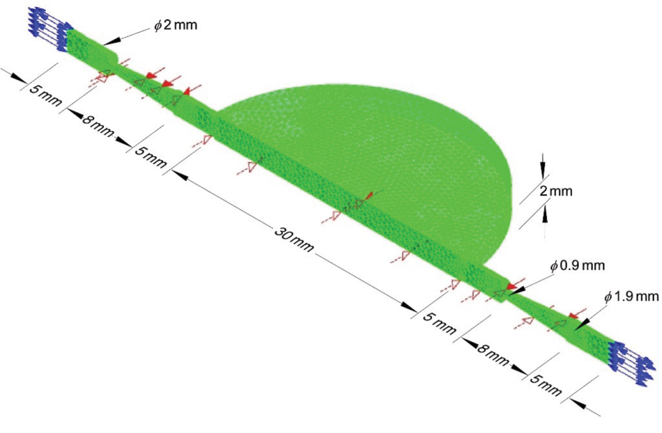
Diaphragm pump model for fluid-flow analysis.
Moving boundary conditions are specified at the faces of piezoelectric actuator, since it has an oscillatory motion. For this purpose, the arbitrary Lagrangian–Eulerian formulation is used, which rearranges the mesh at each iteration, making it coherent with the applied moving boundary conditions (Donea et al., 2004). In this model, nodal displacements and velocities of the piezoelectric actuator immerse in water, found in previous harmonic analysis, can be prescribed as boundary condition in fluid-flow simulation. From these results, it is possible to find a polynomial equation that reproduces approximately the oscillatory behavior of the piezoelectric actuator in their first vibration mode. Multiplying this polynomial equation by
Figure 9 shows flow rate and pressure head curves obtained by computational simulations using this higher hierarchy model until a total simulation time of 0.1 s, considering applied voltage of 320 V pp and excitation frequency of 45 Hz. In this kind of pump, fluid flow occurs in both directions and, thus, from curves of Figure 9, average values for flow rate and pressure head are calculated to be equal to 22.5 mL/min and 95 mmH2O, respectively. These values will be compared with experimental values described in ‘Experimental Results’ section.

Obtained curves at simulation time of 0.1 s: (a) flow rate versus time and (b) pressure head versus time.
Sensitivity Analysis Conducted Using a Simplified Model
Here, results obtained from a sensitivity analysis for geometrical parameters of nozzle/diffusers (D, d, and
In order to reduce CPU time, a simplified 3D computational model of the piezoelectric diaphragm pump, shown in Figure 10, is built. The FE mesh of this simplified model has 26,756 elements, and a cubic format is assumed for pump chamber region (see Figure 10).
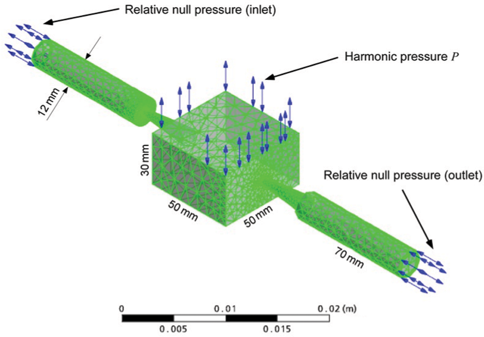
Simplified model for fluid-flow analysis.
Fluid flow must occur in the horizontal direction, considering that the whole body of the flow pump is submerged in the water medium, that is, relative null pressures are prescribed at nodes of inlet and outlet pumps. Moreover, null displacement and velocities are imposed at the nodes, which represent lateral and bottom walls of the pump chamber and walls of nozzle/diffusers. For this simplified model, the following harmonic pressure value (
A transient analysis is carried out for each parameter combination until a total simulation time of 0.1 s. At this time, the pump has reached a stationary regime, where the generated flow is constant with time. Thus, according to simulation results of this simplified model, it is concluded that the largest average flow rate value occurs for D = 1.9 mm, d = 0.9 mm, and considering nozzle/diffuser length (
Experimental Results
Manufacturing Prototype
An experimental prototype is built for validation purposes, for checking the viability of flow pump construction, and for observing any incident phenomena not considered in the computational simulations. Figure 11 shows a view of the diaphragm pump prototype, which consists of inferior base plate, pump chamber (50 × 50 mm), two nozzle/diffusers, inlet and outlet connectors, and a low-cost piezoelectric actuator disk clamped on superior base plate. The materials of the pump chamber and nozzles are acrylic. Base plates and nozzle/diffusers are manufactured in aluminum. All components are manufactured by conventional low-cost cutting processes, using a Computer Numeric Control (CNC) machine, and electrical discharge process.
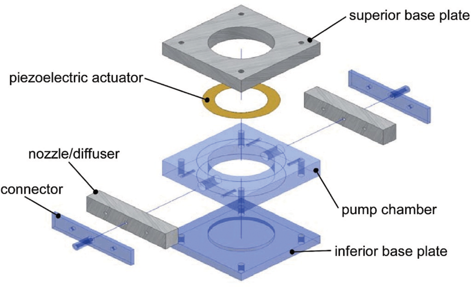
Exploded view of the manufactured prototype.
Experimental Characterization
To drive the experimental characterization of the diaphragm pump prototype, a HEWLETT PACKARD 4194A impedance analyzer is used for mapping resonance frequencies of the prototype. The piezoelectric actuator is actuated by a harmonic generator and amplifier INOVEO FG1000 (designed and built to this experiment). Knowing the prototype resonance frequencies, the flow rate evaluation of the piezoelectric diaphragm pump is performed. The experimental setup used in simulations is shown in Figure 12. It consists of associating a glass pipe of circular section, with known area and length (

Flow rate experimental measurement.
A colored pigment is injected at inlet pump to allow the fluid-flow visualization, as shown in Figure 13. PZT disk of the actuator must operate out of the water reservoir to avoid lifetime reduction of diaphragm pump.
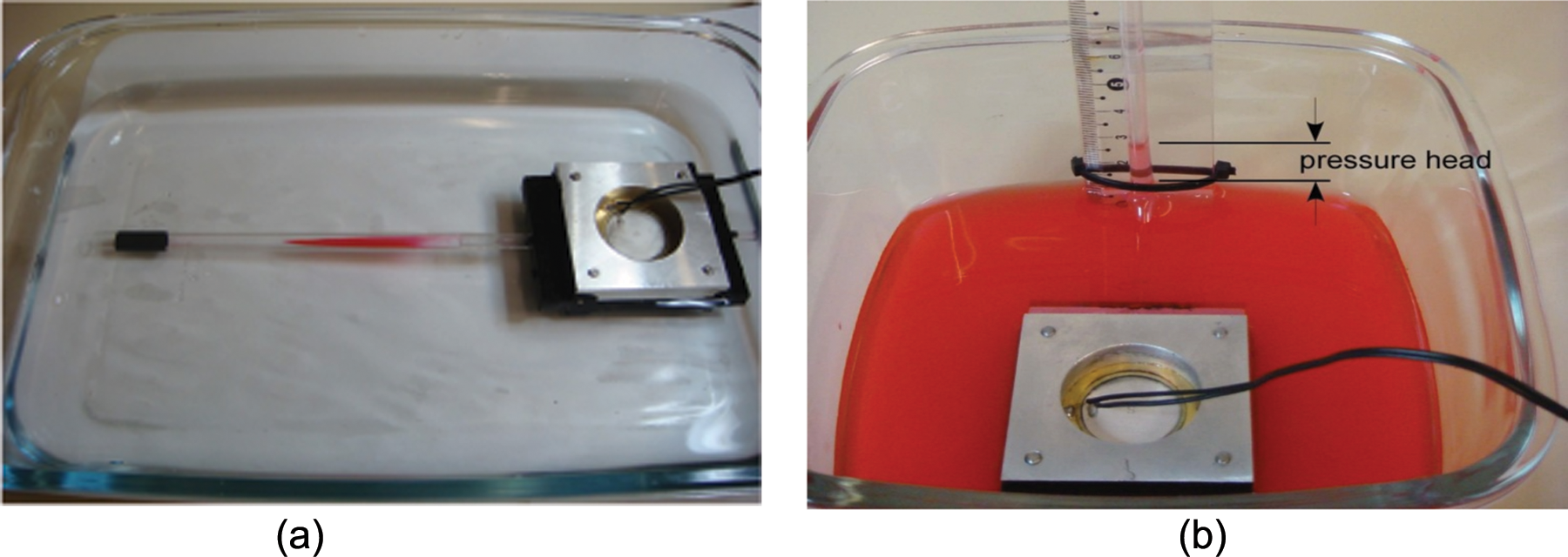
(a) Fluid flow and (b) prototype pressure head visualization.
To evaluate the pressure head (the fluid’s energy per unit weight) produced by the diaphragm pump, the prototype is positioned as shown in Figure 14. The pump inlet remains inside the reservoir and the pump outlet is connected outside the surface of the reservoir, using a curved tube (see Figure 14). The diaphragm pump is turned on and, then, the water column height (pressure head) generated in outlet pump is measured by a scale rule.
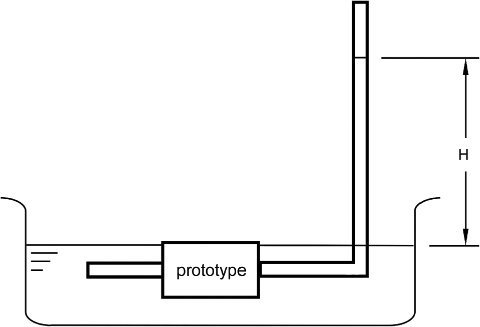
Pressure head experimental measurement.
To evaluate the performance of diaphragm pump prototype subjected to different excitation frequency values (Hz), flow rate and pressure head versus frequency curves are obtained, keeping the same applied voltage value (320 V pp ). Figure 15 depicts the performed frequency range, showing a maximum average experimental flow rate value equal to 23 mL/min, at the resonance frequency of 45 Hz, with a standard deviation of 0.94 mL/min, and uncertainty of about 10% for each measured flow rate pointed in Figure 15.
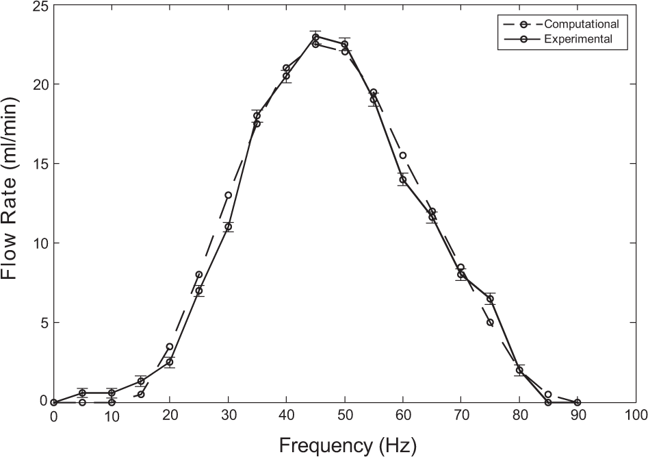
Computed and measured flow rate versus frequency curves.
The pressure head versus frequency experimental curve obtained using the prototype of diaphragm pump is shown in Figure 16. According to this plot, a maximum experimental pressure head value of 93 mmH2O is achieved at an excitation frequency of 45 Hz. For the pressure head measurement, the uncertainty value of 0.5 mmH2O is found for all measured points indicated in Figure 16.
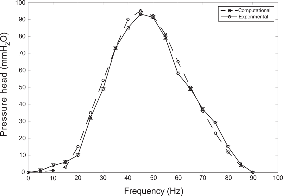
Computed and measured pressure head versus frequency curves.
Figures 15 and 16 also show a comparison between experimental and calculated flow rate and pressure head curves (dashed lines), respectively, which show reasonable agreement between both methods (experimental and computational) employed to develop the piezoelectric diaphragm pump.
Finally, experimental and computational flow rate versus pressure head curves can be seen in Figure 17, which are obtained at 45 Hz (resonance frequency) and 320 V pp (peak-to-peak applied voltage). According to this plot, computational curve (dashed line) is close to the experimental curve, which certifies the computational simulations proposed in this work.
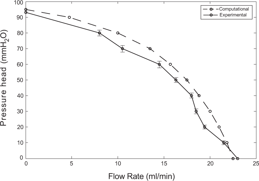
Computed and measured flow rate versus pressure head curves.
Working conditions of the diaphragm pump can be determined by curves of Figure 17, which indicates the level of flow rate at a desired pressure head. Moreover, according to plots of Figures 15 and 16, there is a frequency range in which different flow rates and pressure heads can be obtained by just varying linearly the excitation frequency of the piezoelectric actuator. Then, this parameter can be a way to control the response of the diaphragm pump.
Conclusion
A methodology for development of a low-cost piezoelectric diaphragm pump (valveless type), using FE modeling and experimental prototype, is presented. Sensitivity analyses are carried out to identify the best geometrical parameters of diaphragm pump. It is concluded that resonance frequency is significantly modified when eccentricity between piezoelectric disk and metallic plate occurs. Thus, a precise assembly between PZT disk and metallic plate is fundamental to assure better performance of the diaphragm pump. According to the results presented in this work, maximum experimental flow rate and pressure head values of 23 mL/min and 93 mmH2O, respectively, are achieved at the resonance frequency of 45 Hz. By comparing the results obtained from computational simulations and experimental prototyping, it is concluded that computational simulations provide results whose magnitude is close to the experimental results, certifying the numerical models built to simulate and analyze the diaphragm pump behavior.
As a future work, other configurations using more than two piezoelectric actuators, in series assembly, will be investigated to increase the diaphragm pump performance.
Footnotes
The authors would like to acknowledge the Brazilian research sponsors FAPESP (Sao Paulo State Foundation Research Agency), Grant Nos. 2004/14675-0 and 2011/02387-4, and CNPq CNPq (National Council for Research and Development), Grant Nos. 303689/2009-9 and 500991/2009-0, for the financial support provided for this project.