
Abstract
The so-called McKibben artificial muscle is one of the most efficient and currently one of the most widely used fluidic artificial muscles, due to the simplicity of its design, combining ease of implementation and analogous behaviour with skeletal muscles. Its working principle is very simple: The circumferential stress of a pressurized inner tube is transformed into an axial contraction force by means of a double-helix braided sheath whose geometry corresponds to a network of identical pantographs. However, behind this apparent simplicity lie two phenomena, which must be considered so as to fully understand how the McKibben muscle works. First, the non-linear relationship between stress and strain inside the inner tube elastomer, together with the complex relationship between physical artificial muscle parameters and its effective working pressure range. Second, the behaviour of the braided sheath which acts like a ‘flexible joint structure’ able to adapt itself during contraction to the increasing radius muscle in its middle portion, with the boundary constraint of rigid tips. By distinguishing an ideal model with a zero inner tube thickness from a real model with a non-zero inner tube thickness, we attempted to synthesize static models by including and excluding an elastic force component. However, we also highlight the possible need, in further modelling, to distinguish modelling thin-walled from thick-walled inner tube McKibben muscles. In our attempt to understand the hysteresis peculiar to the muscle, it seems, resulting from our review, that this hysteresis phenomenon is essentially due to strand-on-strand friction inside the weave. Nevertheless, although Hertz’s contact theory has shown its relevance in tackling this problem, friction modelling in a McKibben muscle is particularly hard due to the difficulties, first, to correctly determine the real contact surface strand-on-strand and, second, to estimate the friction coefficient and its possible dependence on pressure and velocity with the weaving peculiar to McKibben braided sheaths. We propose in a future approach to better integrate textile physics into this very complex modelling problem. Moreover, because we consider friction to be velocity-dependent, a distinction between static and dynamic modelling appears necessary to us and can help, in our view, towards a better understanding of the Hill-like character (or not) debate concerning artificial muscles.
Introduction
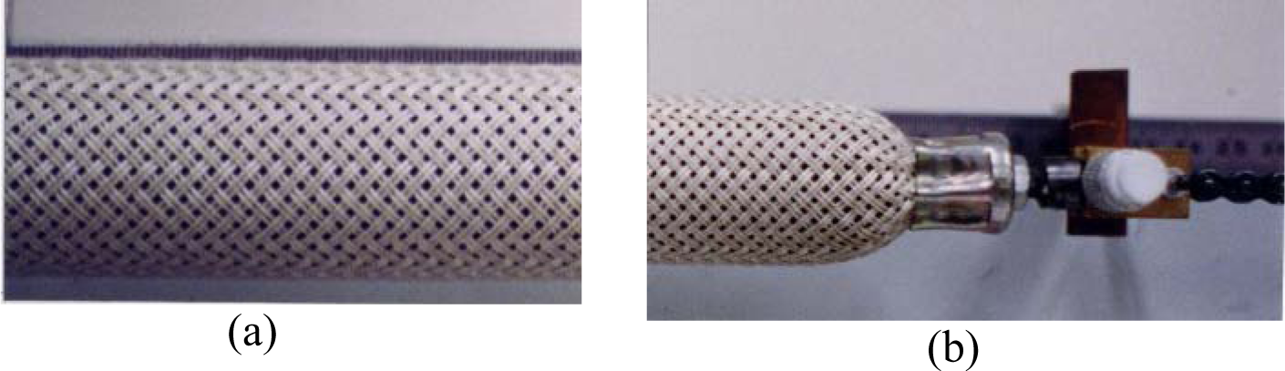
The so-called McKibben artificial muscle is a remarkable invention. Technically speaking, it is essentially a rubber or elastomer inner tube surrounded by a common double-helix-braided sheath, as illustrated in Figure 1(a): when an internal pressure is generated inside the bladder, the free tip of the artificial muscle contracts while the external sheath maintains its cylindrical shape in a wide middle part. A McKibben muscle can be easily constructed and put into use if a moderate pressure source is available. The invention of this artificial muscle is generally attributed to Richard H Gaylord (1958) who described the actuator as ‘an elongated expansible tubular means surrounded by a woven sheath forming an expansible chamber which contracts in length when expanded circumferentially’, but it was popularized at the beginning of the 1960s by Joseph L McKibben, after his daughter had been paralyzed by polio (he was ‘famous’, wrote the Life magazine, was known ‘as the man who pushed the switch to detonate the first A-bomb’) (McKibben, 1960: 87). McKibben’s device was used initially as a pneumatic actuator – sometimes in combination with standard pneumatic cylinders – of orthotic systems attached to a wheelchair (Allen et al., 1962; Engen, 1965; Nickel et al., 1965) or more simply braced to the forearm as shown in Figure 1(a) (Engen, 1963; Nickel and Garrett, 1963). At that time, the advantages of the artificial muscle were described as follows (Snelson et al., 1961):
One advantage of the artificial muscle over a piston and cylinder is that an artificial muscle has no static friction [sic] [and thus no] uneven, jumpy action […]. Another advantage of the artificial muscle is that alignment is not critical. […] A third advantage is its weight (p. 348).
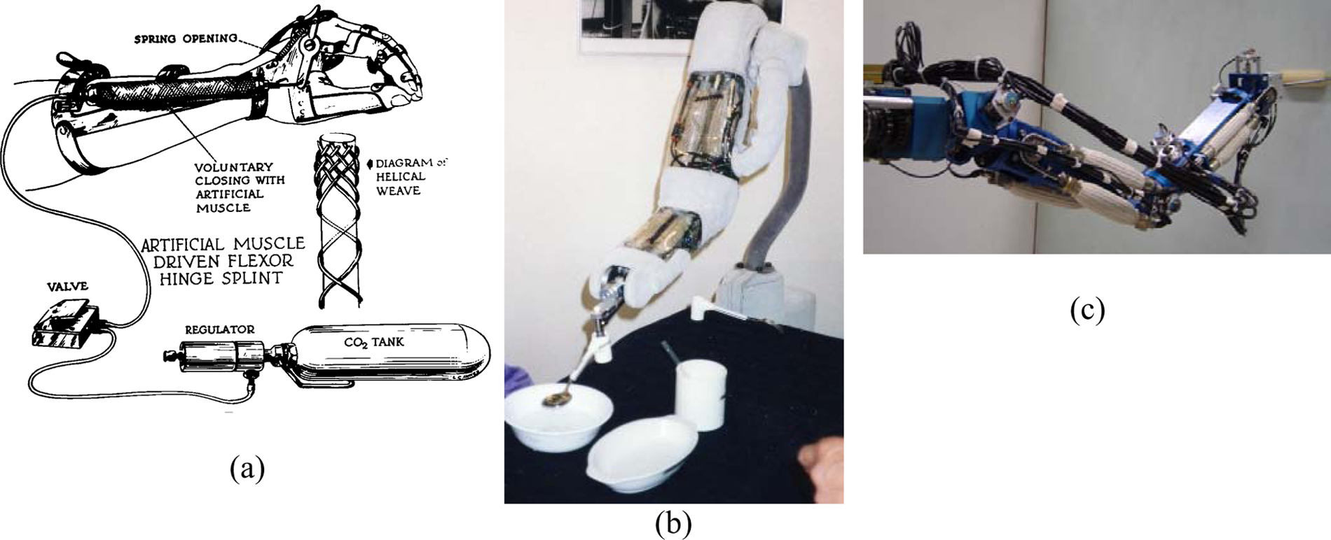
Past and current use of the McKibben artificial muscle: (a) original use as a prosthetic actuator in the 1960s (from (Allen et al., 1962)), (b) renewed version designed by Bridgestone in the 1990s (photograph taken by the author during the 1993 ICAR-exhibition in Tokyo) and (c) current use as a soft actuator for Service Robotics (prototype developed at the University of Toulouse (Tondu et al., 2005)).
But it is also mentioned in the same article that its main disadvantage is its inability to produce a great force through a great excursion. These reasons can explain its main application in the design of powered finger prehension orthosis. However, even limited to this application field, its use required a heavy embedded pressurized CO2 tank due to its high gas consumption (explained in the following). Thus, it seems that after a brief commercial use, it was forgotten once small electric motors with lighter batteries became effective and cheap. Let it also be noted that to better explain the oblivion of this invention, it has always been difficult to design efficient and acceptable active orthotic devices or robots for disabled people.
In the decades which followed, the place of electric motors in automatic and robotic systems based on increased reliability and the invention of reduced size, such as the well-known harmonic drive gears, became more commonplace. Only recently, in the 1980s and 1990s, did the McKibben artificial muscle regain its renown, notably since Bridgestone’s engineers launched a renewed version, called ‘rubbertuator’ (EPW, 1984; Bridgestone Corporation, 1987; Bridgestone Corporation and Taicubo Engineering, 1993) (see Figure 1(b)) and introduced it into robotics with the aim of developing more human-friendly robots mimicking natural skeletal muscle compliance. Due to the fact that the structure itself of the McKibben muscle now belongs to the public domain, other industrial companies offered their own version of the muscle, such as the ‘digit muscle’ of the Shadow Robot Group (Greenhill, 1993; Shadow Robot Group, 1994) or the Festo (2001) company’s ‘fluidic muscle MAS’. The question of controlling the McKibben artificial muscle considered on its own or by antagonistic pairs (see Figure 1(c)) will not be dealt with in this article; instead, this review concentrates on its modelling.
It is clear that the renewal of interest in McKibben artificial muscles is linked to the recent development of bio-robotics or bio-inspired devices. What is the place of McKibben artificial muscle in this quest for a bio-inspired artificial muscle? For some specialists, a true artificial muscle must transform chemical energy into mechanical energy, in the way animal muscles do. However, among the multiple recent attempts – see, for example, the excellent and very relevant review by John Madden et al. (2004) – no chemo-mechanical artificial muscle offers sufficient power and reliability in actuating mechanical devices weighing a few kilograms. As a result, only purely mechanical fluidic artificial muscles are able to be used today as an alternative actuation mode for the electric actuator, in either mechatronics or robotics. Among the relatively large family of fluidic muscles – see, for example, Daerden and Lefeber’s (2002) review – the artificial muscle is particularly interesting due to its spindle-like shape and its biomimetism, easily highlighted by its use. However, its accurate modelling is particularly arduous because it combines multiple difficulties in the physics of elastic and soft materials. In this review, we try to take stock of the static and dynamic modelling of McKibben muscles. In addition, beyond the special case of McKibben muscles, we are of the opinion that the problems research workers encounter and the responses they try to provide can help to better understand some of the major difficulties peculiar to a large part of fluidic artificial muscles. Their efforts go beyond this, and it is to help foster a better understanding of what can be called new ‘soft’ actuators. The review is organized as follows: in the ‘Notion of artificial muscles’ section, we try to specify the general notion of artificial muscles and to justify why McKibben muscles are so called; in the ‘Working principle of the McKibben artificial muscle’ section, we develop its functioning principle and the primary modelling directly deriving from this principle; in the ‘Advanced static modelling of the McKibben muscle’ section, we analyze the problems to deal with in order to progress to an advanced static modelling, and in the ‘Dynamic modelling of the McKibben muscle’ section, we attempt to justify the notion of dynamic modelling, applied to the case of McKibben muscles.
Notion of artificial muscles
It is clear that McKibben artificial muscle, as for other forgotten 1960s’ attempts (such as, for example, the early version of ‘straight-braided’ pneumatic muscle constrained by intermediate rings (Matsushita, 1968)), took advantage of advances in rubber technology, which started to emerge after the Second World War. As analyzed in the ‘Working principle of the McKibben artificial muscle’ section, the muscle structure can be allied to that of tyres. Another – less obvious, however – connection can be made with the discovery in the late 1940s of the possibility of actively and reversibly controlling the shape change of certain polymers, as emphasized in the seminal article published by the Kuhn et al. (1950): by means of a pH variation, a hydrogel can be reversibly contracted and elongated without breaking. The authors clearly relate their experiment with the hope ‘(of imitating) to a certain degree, the reversible dilatations and contractions of biological systems’. Still, according to these authors, what can be considered as being the first chemo-mechanical artificial muscle is based on an equilibrium principle between two ‘opposing tendencies’– the expression is used in a previous article (Katchalsky, 1949): a first tendency of the material to expand, counterbalanced by retractile forces. We consider that any artificial muscle, and thus the McKibben artificial muscle, is founded on a general ‘equilibrium principle’ according to which the artificial muscle in response to a constant stimulus, changes its shape from a given equilibrium position to another one, as does a natural muscular tissue when it is chemically or electrically stimulated. In control terms, this property can be expressed by stating that the positioning of any artificial muscle is stable in open-loop. As a result, it is clear that the electric motor is not an artificial muscle such as a fluidic cylinder, since in response to a constant pressure the cylinder moves until reaching its stop block although slowed down by friction. Finally, it can be considered that, according to this restrictive definition, artificial muscles define a new class of actuators different in a general way – although this generalization is open to question – from the other two classes of actuators, those whose velocity is stable in open-loop (such as electric motors), or those whose position nor velocity is stable in open-loop (such as fluidic cylinders).
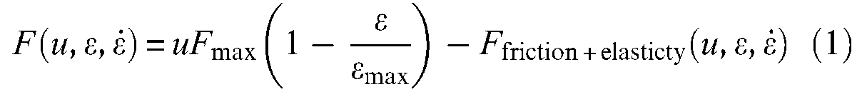
This equilibrium principle or open-loop positioning stability can also be interpreted in the general framework of stability in physics: when an artificial muscle, controlled by a constant value stimulus, is moved away from its equilibrium position, a returning force occurs returning it to this equilibrium position. This leads to a technical interpretation of artificial muscles as an ‘active spring,’ which is also a possible phenomenological definition of the contractile element of human skeletal muscles – see for example equivalent mechanical schemes proposed by C Ghez (1991). The definition of artificial muscles as an open-loop positioning actuator and its interpretation as an active spring finally meets the phenomenological characterization of natural skeletal muscles by means of the well-known tension-length and tension-velocity curves. The first one, illustrated in Figure 2(a), resulting from an isometric contraction 1 study, corresponds to a static modelling of skeletal muscles. It is, however, important to stress that this tension-length curve includes a passive tension component peculiar to natural muscular tissues that is generally not considered in the definition of artificial muscles essentially limited to the active contraction–elongation phenomenon. The second one, illustrated in Figure 2(b), resulting from a particular form of isotonic contraction 2 study (see ‘Dynamic modelling of the McKibben muscle’ section), corresponds to a dynamic modelling of skeletal muscles whose main objective consists of characterizing the way natural muscular contraction is damped. By analogy with these two phenomenological curves, the definition of artificial muscles as an active spring can be more accurately specified as a naturally damped active spring, whose general and simplified model could be presented as follows:
in which F designates the force produced by a normalized stimulus u,

where Factive spring is now defined by a linear or non-linear spring characteristic with, however, the assumption of a stimulus-proportionality of static characteristics. In some ways, the modelling of a McKibben muscle consists of determining as accurately as possible the two functions Factive spring and Ffriction + elasticity.
Typical (a) tension-length and (b) tension-velocity skeletal muscle curves emphasizing, respectively, the active spring-like static behaviour of skeletal muscles whose neural activation level modifies ‘spring’ stiffness and the naturally damped dynamic behaviour of skeletal muscle in the form of Hill’s curve (see ‘Dynamic modelling of the McKibben muscle’ section).
Working principle of the McKibben artificial muscle
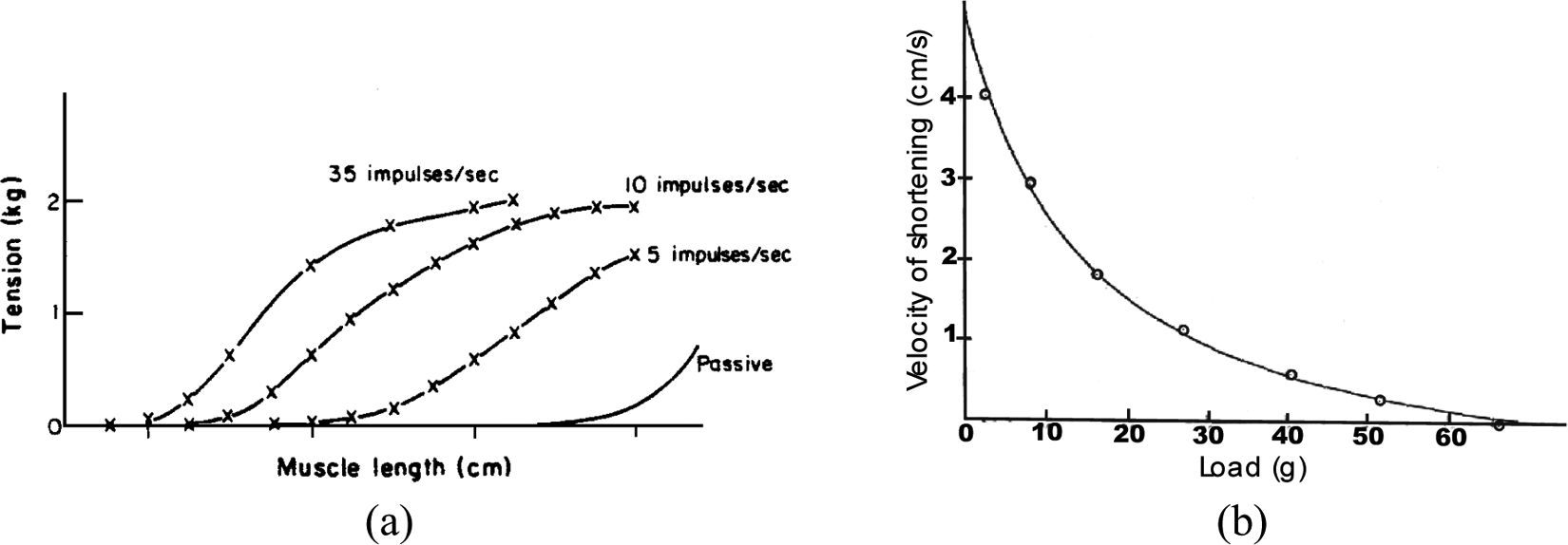
Typically, a McKibben artificial muscle behaves as illustrated in Figure 3: when a pressure is imposed at a constant value inside the inner tube, a contraction force is produced decreasing with the contraction ratio, which is defined as the ratio between muscle-length reduction and its initial length. Let us note that there are two ways of representing static characteristics of McKibben muscles. The first, inspired by physiology, represents the contraction force as an increasing function of muscle length with respect to a minimum muscle length corresponding to a zero static force – see, for example, (Ghez, 1991). This bio-inspired representation mode is that adopted in the first studies of McKibben muscle modelling (Pearson, 1966; Schulte, 1961). Such an approach could be motivated by the fact that, in analogy with skeletal muscles, among the first McKibben muscles, some prototypes exhibited wide passive extension with respect to their relaxed state length – sometimes called ‘free length’, that is, ‘inflation pressure and external tension = 0’ (Schulte, 1961: 97 and also Figure 1, p.101); this could be due to a non-fully braided sheath covering of the rubber inner tube. More recently, Chou and Hannaford (1996) adopted this representation mode. However, as we will try to highlight further, if inextensible strands are used in the design of a weave fully covering the bladder, the McKibben muscle becomes theoretically and, almost in practice, globally inextensible. The second, a representation mode of static force as a decreasing function of contraction ratio, which is defined as the ratio between positive length variations during contraction over initial muscle length – see later in our definition of variable ε in equation (3) – can thus appear more adapted. Bridgestone Corporation’s (1987) engineers seem to be the first to have adopted this representation mode, also used by Festo (2001) engineers or researchers such as Caldwell’s team (Davis et al., 2003). This is also the notation favoured in this review and used in Figure 3.
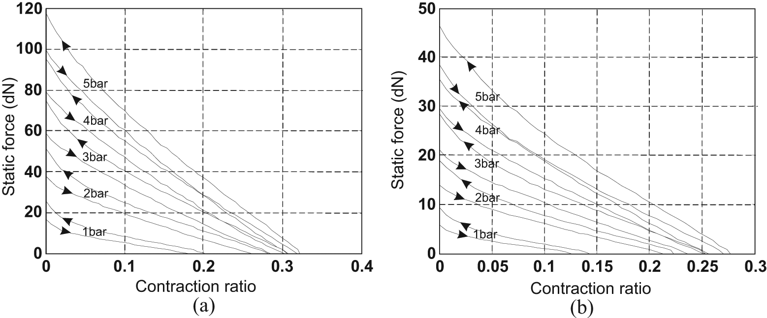
Typical static force produced by a McKibben artificial muscle emphasizing the role of control pressure, the hysteresis phenomenon and the fundamental role of the braided sheath initial angle: the two artificial muscles have the same initial length and radius – defined later by l0 and r0 (l0 = 30 cm and r0 = 0.7 cm) – but a braided rayon weave with two different initial braid angles – defined later by α0: (a) α0 = 20°, (b) α0 = 30°.
Several phenomena on these curves can be underlined:
The active spring-like character of McKibben muscle: control pressure P plays the role of skeletal muscle neural activation and, moreover, maximum static force appears to be roughly proportional to P.
In a large portion of the curve static force versus contraction ratio, the force decreases linearly with contraction ratio.
Maximum contraction ratio, however, appears to be dependent on pressure in a complex way, with relatively weak values at low pressure.
Artificial muscles exhibit a wide hysteresis, which leads to distinguishing the force produced during quasi-static contraction (descending arrow) from the force produced during quasi-static elongation (ascending arrow).
The maximum force produced can be relatively high for moderate pressures in comparison with similar sized fluidic cylinders. Moreover, it practically appears that the same maximum force can be obtained by different choices of parameters peculiar to the initial size of the artificial muscle or its typical braided sheath.
To explain these phenomena, we propose to introduce a first distinction between an ideal notion of artificial muscle (‘Notion of ideal cylindrical artificial muscle’ section), subsequently applied to McKibben muscles (‘Ideal McKibben muscle’ section), before dealing with the realization of the artificial (‘Achievement of the McKibben muscle’ section).
Notion of ideal cylindrical artificial muscle
An ideal cylindrical artificial muscle can be defined as a pressurized cylinder able to reduce its length l while its radius r increases, according to a predefined positive function f(ε) such as:
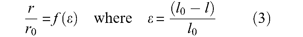
where r0 and l0 are the initial muscle radius and length, respectively. Variable ε will designate the artificial muscle contraction ratio throughout this article. Let us denote F(ε) muscle contraction force as a positive value; it can be determined from a simple virtual work analysis, as illustrated in Figure 4. Let us assume that the muscle is fixed at one tip and that its free tip is put into equilibrium by the positive force F. Since δr > 0 when δl < 0, application of the virtual work theorem leads to 3


Application of the virtual work theorem to the definition of the contraction force of a cylindrical artificial muscle characterized by its contraction function (r/r0) = f(ε).
Since, furthermore, we obtain,

defined as long as F(ε) is positive, that is, when muscle volume increases, since we can also write

or, more synthetically, as proposed by Chou and Hannaford (1996):

where
Ideal McKibben muscle
Let us consider a planar network of jointed identical pantographs as considered in Figure 5 composed of m columns and n rows whose envelope is a rectangle of initial length l0 and width L0. Moreover, the initial angle of each elementary pantograph is denoted α0.
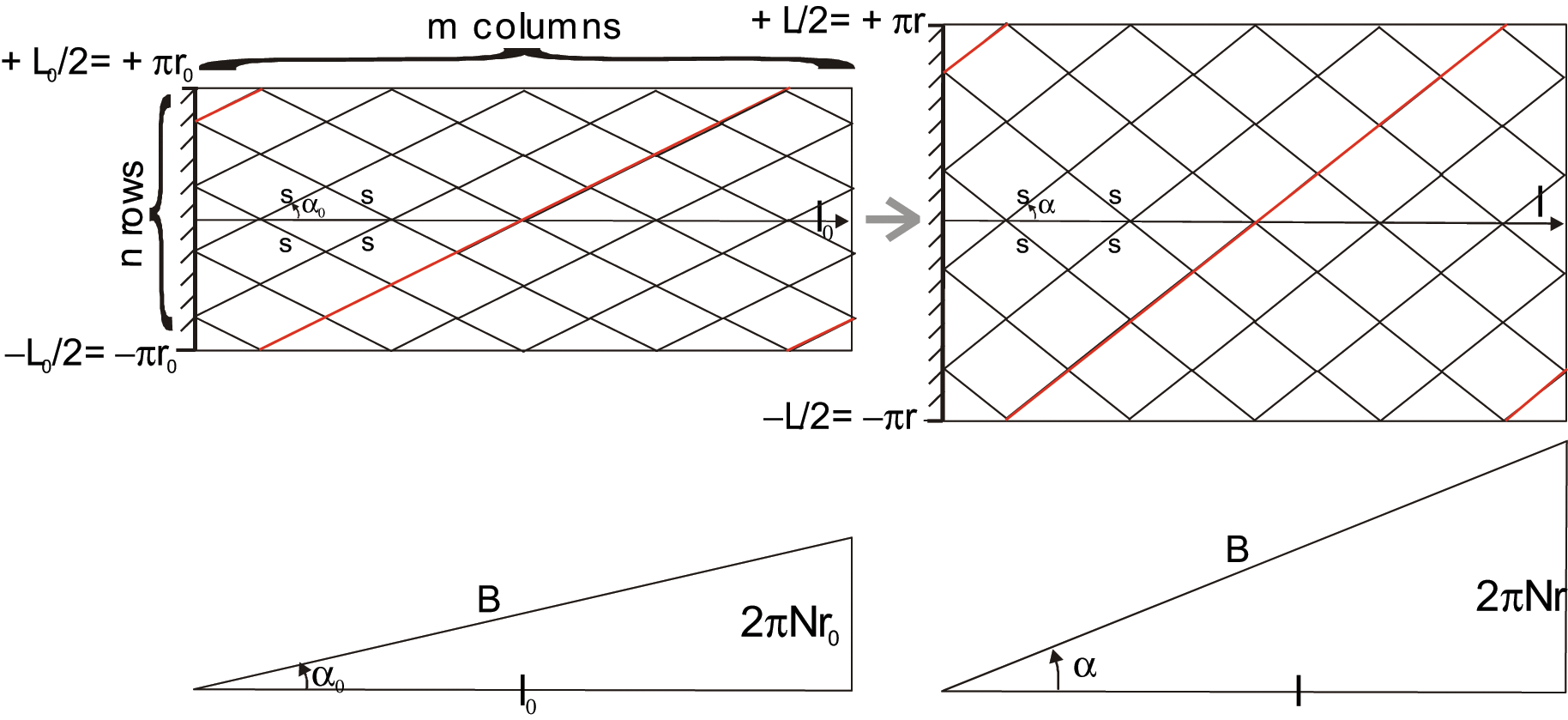
Geometrical characterization of the braided sheath of the McKibben muscle (see text).
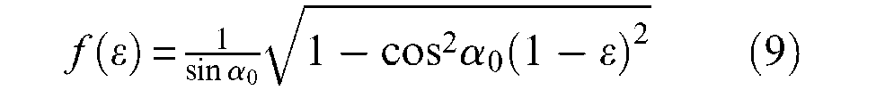
When the network moves from angle α0 to current angle α (α > α0), it maintains its rectangular shape with a width increasing from L0 to L and a length decreasing from l0 to l. Let us now assume the possibility of a soft pantograph network in the form of a cylinder whose initial radius is r0– that is, L0 = 2πr0– and current radius is r– that is, L = 2πr. Let us subsequently assume that the side of each ‘bent’ pantograph, noted s, can effectively remain constant during the ‘contraction-elongation’ process – this assumption will be justified later. We thus derive the following relationship:
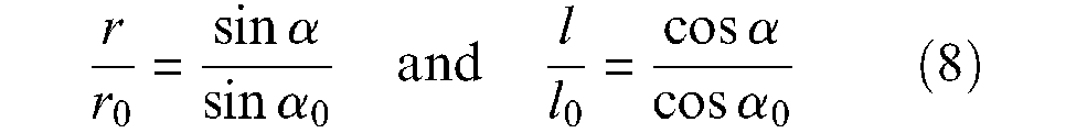
which is in fact a standard result in tyre design calculations (Woods, 1944). We subsequently derive the following contraction function f(ε) from these two expressions:
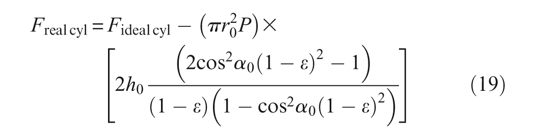
We propose to characterize an ideal McKibben artificial muscle as being an ideal cylindrical fluidic artificial muscle (as defined in a previous paragraph) whose contraction function is given by equation (9). If we now apply the general muscle force equation to this contraction function we deduce the following expression of F(ε), that will now be denoted Fideal cyl (ε), to distinguish it from this, corresponding to a further cylindrico-conical ideal model:
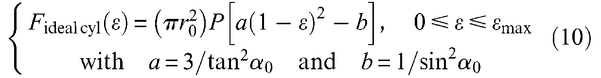
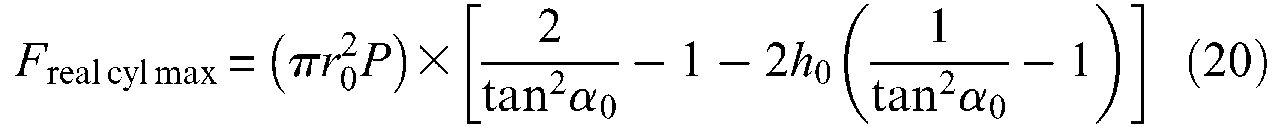
We deduce the following expressions of maximum force obtained for ε = 0 and of maximum contraction ratio obtained when force is 0, as also the expressions of maximum radius and maximum braid angle:
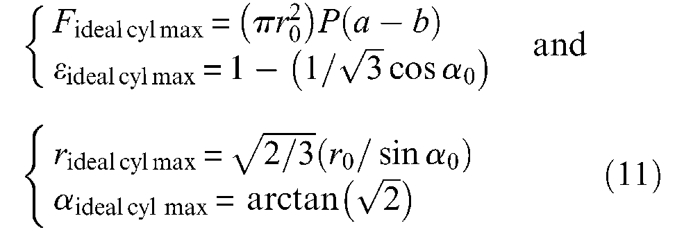
Among these four results, two are more noteworthy: first, the maximum force expression highlights the possibility of increasing the maximum force of artificial muscles to much higher than that of an equivalent initial section fluidic cylinder thanks to the choice of a weak initial braid angle; second, it appears that whatever the geometric parameters of artificial muscle and its control pressure, maximum braid angle value is equal to arctan
A first alternative expression of ideal McKibben muscle force can be obtained in choosing to parameterize force as a function of α angle instead of ε, and in considering r90° = r0/sinα0. We then obtain from equations (8) and (10):

This expression corresponds to the main term of Schulte’s (1961) model. A second and still older alternative expression to characterize ideal McKibben muscle force consists of specifying the pantograph network not by initial angle α0, but by length B of a cord and the number N of turns of this cord, from one tip to the other (see Figure 5). We obtain
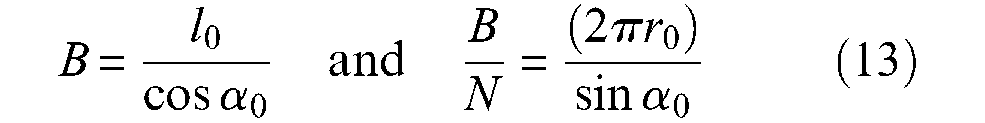
Let us write λ2 = l/l0=(1−ε)−this variable will be used later with same meaning, we deduce from equations (10) and (13), the new force expression originally derived by Gaylord in his patent:
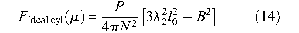
The three proposed formulae of the ideal McKibben muscle force are obviously equivalent, and they only differ by the choice of their variable and geometric parameters: variable ε and parameters l0, r0 and α0 in the initial proposed model, variable λ2 and parameters l0, B and N in Gaylord’s model, variable α and parameter r90° in Schulte’s model. The latter one could appear as the most economical but this is misleading because, first, α is not directly measurable and, second, r90° has no physical meaning since it corresponds to the unreachable radius of the pantograph network when α = 90°. If the variable is muscle length or muscle contraction ratio, three independent parameters appear necessary to specify the force model of this ideal McKibben muscle. The question now becomes: is this ideal muscle feasible?
Achievement of the McKibben muscle
Two elements are necessary to produce a McKibben muscle: an inner tube or bladder, able to continuously inflate in accordance with the imposed contraction function and an element that is able to transmit pressure forces to the soft network of pantographs. Technically speaking, this second element of a real McKibben muscle is easy to design in the form of a double-helix-braided sheath whose yarns can be made of different materials, as will be discussed later. Let us try to specify the role of each of these two components more accurately.
Role of the braid
The virtual work theorem as was used in the section ‘Notion of ideal cylindrical artificial muscle’, does not explain how the braided sheath makes the transmission of pressurized forces possible. This understanding needs to consider a more detailed force analysis. We now consider a rubber inner tube whose initial radius r0 and current radius r designate its exterior radius while the initial and current interior radii are, respectively, denoted ri0 and r
i
. The corresponding initial and current tube thicknesses are, respectively, denoted t0 and ti. Moreover, it is assumed that the pressure is sufficient to assume a full transfer of pressure forces to the braided sheath (see next paragraph for the discussion of this point). Figure 6 illustrates this situation: the rubber inner tube is surrounded by a network of identical pantographs in the form of a matrix
Force analysis in the real cylindrical McKibben muscle (see text).
Let us assume that in any contraction state of the artificial muscle, the full pantograph network remains in contact with the exterior surface of the rubber tube (see the discussion of this point in next paragraph). Thus, for any α angle, each pantograph maintains its side of value constant s, and we can write:

Let f be the positive contraction force produced by each row on the network in the longitudinal direction and fc be the positive force transmitted to each column of the network in the circumferential direction. By simple application of a virtual-work theorem to this network, we obtain
Moreover, it is well known that total circumferential force through full length l of a cylindrical tube is equal – using our notations, to rilP; subsequently, elementary force fc is given by the relationship: fc = rilP/m. By using the expression of n and m given in equation (15), we can derive the following expression of the force generated by the braid sheath, noted Fcyl braid:
This expression emphasizes the following fact: the force directly produced by the braided sheath uniquely depends on rubber tube radii and braid angle, but not on the pantograph network density. If we now take into account pressure force versus free extremity of the artificial muscle, we obtain the following expression of the force generated by what can be called a real cylindrical McKibben muscle – in which any possible friction or elastic effects are naturally not considered:
If we make ri = r in this expression, it is easy to verify that we once again obtain the expression of the ideal cylindrical Schulte’s model given in equation (12). If
Let us limit ourselves now to the case of a thin-walled rubber inner tube. In this case, the assumption of incompressibility can be written as follows: 4 (ri/ri0)(l/l0)(t/t0) = 1 where t = r−ri and t0 = r0−ri0. By considering the equations characterizing the braid change and by disregarding t2 with respect to r2, we obtain the following contraction expression force produced by the real cylindrical McKibben muscle, in which h0 = t0/r0:
By comparison with the ideal force model, this real model is now characterized by four parameters: the three geometric parameters r0, l0 and α0 already considered, and a new one which can be defined either in absolute value by initial rubber thickness t0 or in relative value by ratio h0. In Figure 7, we show a comparison between
from which we deduce a loss of maximum force with respect to the ideal model, respectively, equal to about 9% for α0 = 20°, and to about 8% for α0 = 30° when h0 = 0.01. It also appears that from a certain contraction ratio of about 15%, the two curves, ideal and real, are very close and finally that – although we will not attempt to show it more accurately –maximum contraction ratios are also very close, which suggests, at least in the only case study of thin-walled tubes, that it is not cylindrical inner tube thickness that is responsible for a lower maximum contraction ratio of experimental results with respect to the ideal force model. Let us indeed compare the simulation result of Figure 7 with experimental results given in Figure 3; hysteresis is naturally not concerned in this comparison; the muscle tested in Figure 3 is characterized by an initial section
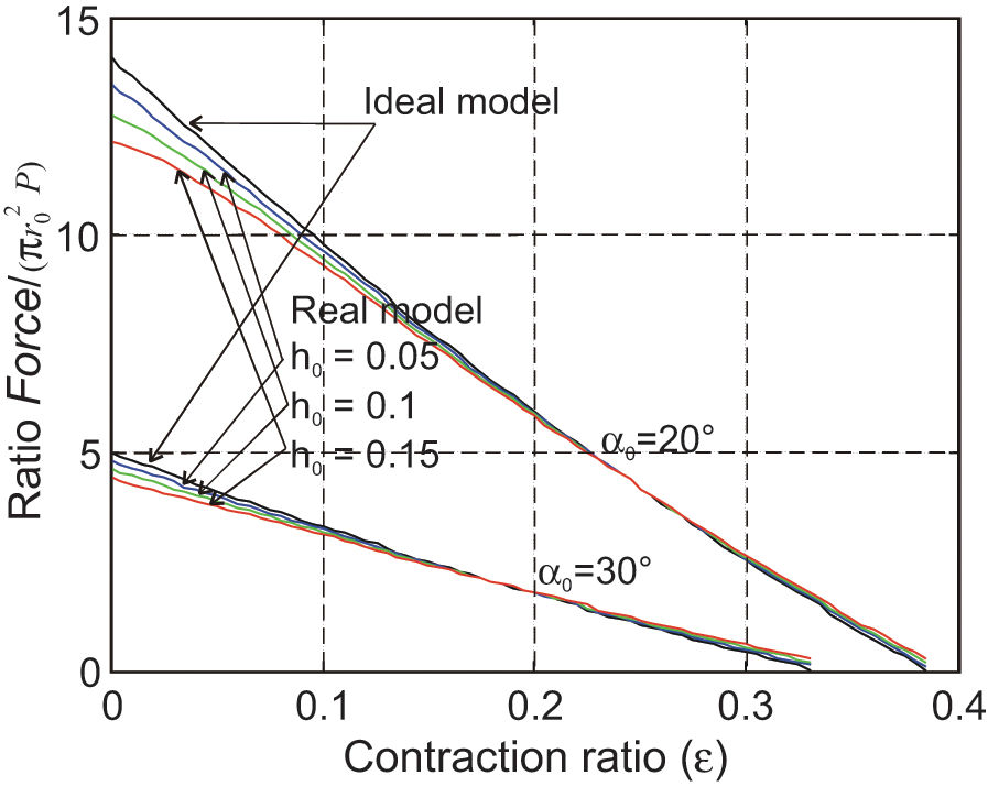
Comparison between the static force model of the ideal cylindrical McKibben muscle model and the real one (h0 designates the initial ratio tube thickness/exterior radius).
Before going further, let us take time to emphasize the practical difficulties in the experimental validation of any static model of McKibben artificial muscles due, in our view, to a double phenomenon: first, if the muscle is designed with an exterior braided sheath, parameter r0 corresponds to the exterior radius of the inner tube in some initial pressure state making possible the contact of the tube versus the braided weave before contraction can begin, and consequently, it is estimated rather than really measured. 5 Second, friction inside the braid limits the evaluation of a primary model deprived of any friction model. Naturally, it can be said that a static frictionless model component could be validated by comparison with the mean curve between quasi-static contraction and elongation; however, an additional phenomenon induces a new difficulty: Friction changes with time and more particularly in the case of a flexible material whose every element, that is, any strand has a certain degree of mobility. Therefore, static-force estimate conditions are highly dependent on experimental parameters (temperature can also be a source of minor errors). Our own experience leads us to believe that an experimental estimate higher in accuracy than about 5% is difficult to obtain.
Finally, it appears that the role of the braided sheath is to transform circumferential stress due to pressure inside the inner tube into a linear contraction force by means of the symmetrical pantograph network realized by the weave through the thickness of the rubber inner tube. This latter remark emphasizes the following fact: pressure generates a circumferential stress which, if the rubber tube makes it possible, is fully transformed by the braided sheath. The result, as analyzed later, is that there is, in our view, no resistive circumferential elastic force to consider during contraction. However, it is this circumferential elastic energy, which permits McKibben muscles to return to its rest state when pressure is relaxed, and so to obtain the fundamental reversibility property of the artificial muscle, as defined in the section ‘Notion of artificial muscle’. In fact, this real model assumes a constant adaptation of the inner tube to the shape variation of the braided sheath. How can the inner tube play this role?
Role of the rubber inner tube
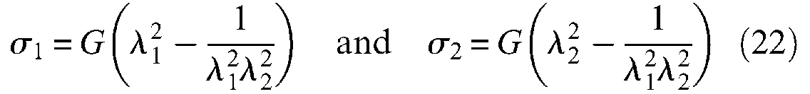
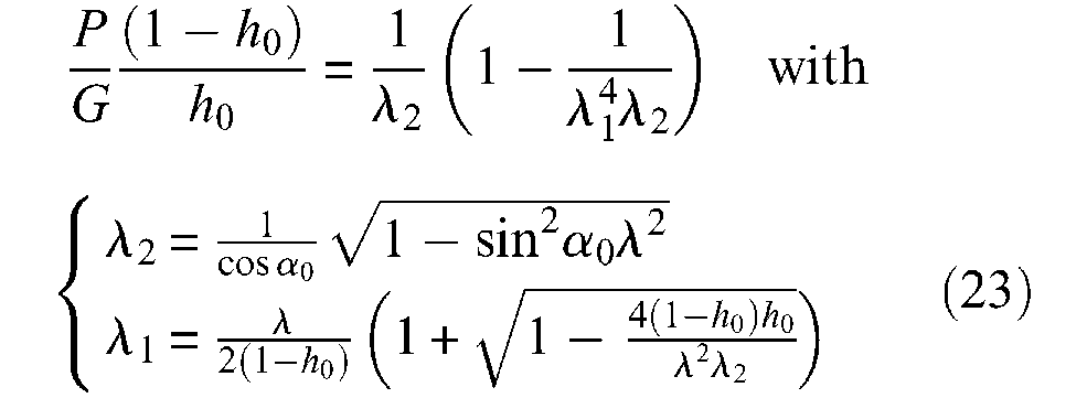
Stability and ballooning effect. It is intuitively clear that only a rubber-like material can be suitable for making the production of McKibben muscles possible due to its resistance to elongation breaking equal to about 680% for 45 International Rubber Hardness Degree (IRHD) 6 natural rubber, and to about 420% for 65 IRDH synthetic rubber. This elongation breaking imposes maximum muscle variation radius on McKibben muscles, and in the case of a cylindrical model a minimum initial braid angle can be deduced from equation (11); in the case of 45 IRDH rubber, it can be estimated to be approximately 6°, which is a very low value underlining the admirable relevance of a large range of rubbers in designing practical McKibben muscles whose initial braid angle is generally chosen as being between 20° and 30°. Large strain physics is subsequently necessary to understand the behaviour of McKibben muscles, and among standard elasticity theories, two are particularly interesting for modelling large strain peculiar to rubber materials: The so-called statistical theory developed by Treloar at the end of the 1940s, and the Mooney (1940) and Rivlin (1948) phenomenological theory that arose in parallel with the development of the former. We will analyze the use of the latter in the section ‘Advanced static modelling of the McKibben muscle’. In our view, Treloar’s theory, although less general, can be particularly relevant for a clear understanding of McKibben muscles, as for other rubber-made artificial muscles. In particular, Treloar’s (1958) theory of rubber elasticity provides a simple set of equations relating the stresses in main directions to the corresponding elongations. Let us consider the assumption of a thin-walled cylindrical elastic tube and strains λ1, λ2 and λ3 defined as follows: λ1 = r i /ri0, λ2 = l/l0 and λ3 = t/t0. According to statistical theory, corresponding stresses σ1, σ2 and σ3 are associated to the strains by the following relationships:

where G is the shear modulus – also rigidity modulus – of the considered rubber. In the case of the thin-walled assumption we can consider that
Johnson and Soden (1966) were among the first to apply these expressions to the peculiar case of thin-walled rubber cylindrical and spherical envelopes and to show the possibility of the unstable behaviour of pressurized envelopes. In particular, as illustrated in Figure 8(a), a cylinder free to expand radially and longitudinally becomes unstable beyond a so-called ballooning pressure depending on ratio (t0/ri0) and on G value: this means that for an imposed inflation pressure greater than the ballooning pressure, the interior radius of the tube as well as its length tends to become infinite and thus increases until the tube bursts. Such a computation can be applied to the case of the inner tube of the real cylindrical model of the McKibben muscle: Circumferential stress is given by formula
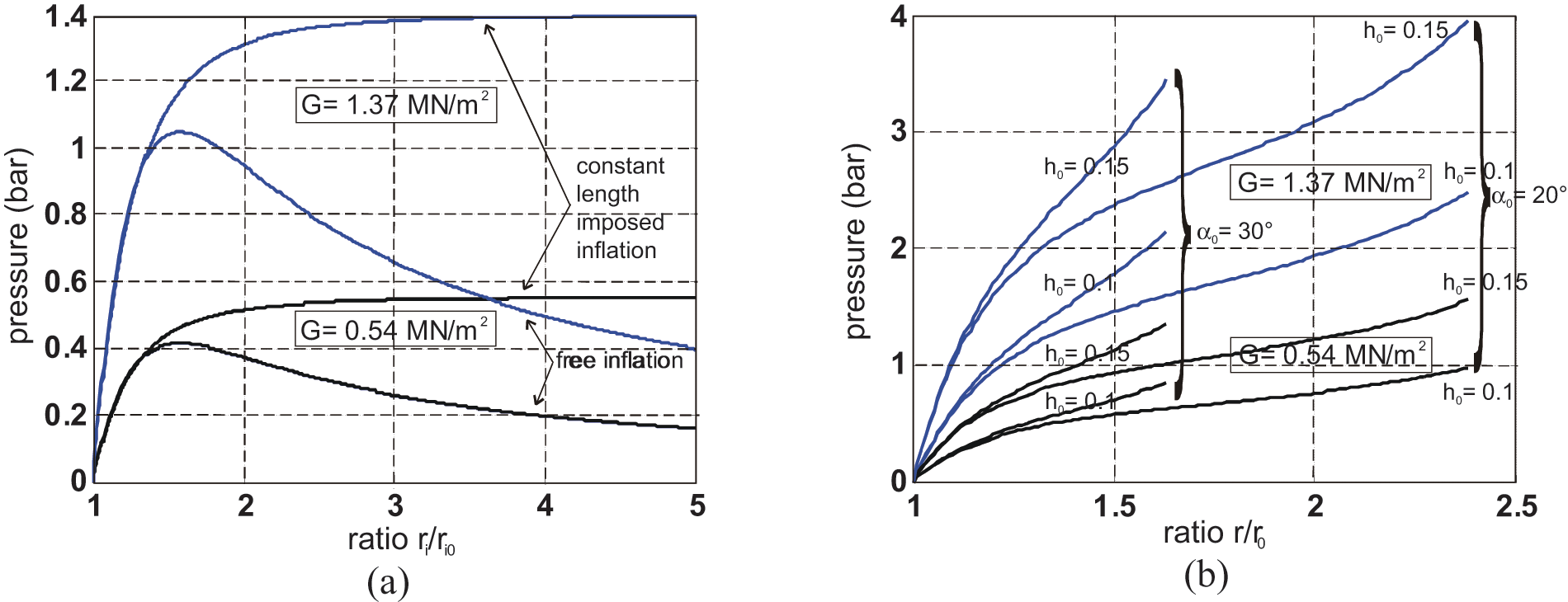
Comparison between radius variations corresponding to an imposed inflation pressure for (a) a cylindrical rubber tube free to inflate, or only constrained in length, and (b) a cylindrical tube constrained by a double-helix braided weave, in two cases of rubber shear modulus (see text for details).
Figure 8(b) shows the corresponding P variation as a function of λ, for two cases of initial braid angle α0 = 20° and α0 = 30°, two cases of h0ratio: 0.1 and 0.15, and for two values of hardness, equal to 45, corresponding to a natural rubber of G = 0.54 MN/m2 and to 65, corresponding to a harder rubber with a G = 1.37 MN/m2.
It is clear on the displayed curves that the McKibben muscle is stable: this means that whatever control pressure, muscle radius – defined as r– as well as its length tends to finite values. We can also deduce the existence of a minimum pressure corresponding to λmax = f(εmax) beyond which it is certain that inflation of the rubber tube will be able to follow the shape variation constraint imposed by the braided sheath, from these curves. In the typical case of an h0 ratio equal to 0.1 and a 45 IRDH rubber, this minimum pressure is equal, respectively, to about 1 bar for α0 = 20° and to about 0.8 bar for α0 = 30°; for a ‘harder’ rubber of 65 IRDH and the same h0 ratio, this pressure reflects, respectively, the values of about 2.5 and 2.1 bar for α0 = 20° and α0 = 30°; in the circumstances of limit-case h0 = 0.15, these values, in the unique case of α0 = 20°, are equal to 2.4 bar, and almost even to 4 bar for 65 IRDH rubber! Although the McKibben muscle designer can advantageously choose a ‘soft’ rubber with a G value closer to 45−50 than to 60−65, it is clear that this minimum working pressure imposed by the laws of rubber elasticity is a real physical constraint for an actuator whose maximum working pressure range in practice is generally limited to 5 or 6 bar. More generally, what we can paradoxically call a ‘ballooning constraint’– that is, the fact that the rubber inner tube can freely inflate until the braided sheath stops it – induces a not always mentioned compromise between a large pressure range working, and a long life duration measured in numbers of contraction-elongation cycles. The first requirement leads to favouring a soft rubber and a low initial ratio rubber tube-thickness over interior-radius in order to obtain a minimum pressure close to 0.5 bar, but these two qualities increase McKibben-muscle fragility. Its ‘weak point’ is indeed not its braided weave but its rubber inner tube. If, as we have emphasized, the rubber-breaking elongation seems to be well adapted to the design of thin-walled inner tube McKibben muscles, breaking stress, which we denote σ b , can be a source of difficulty: from the circumferential stress formula applied to this maximum admissible stress, we obtain σ b = Pmaxri/t, where Pmax is the maximum admissible pressure at each contraction state, we thus deduce:
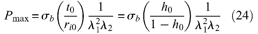
Let us consider value
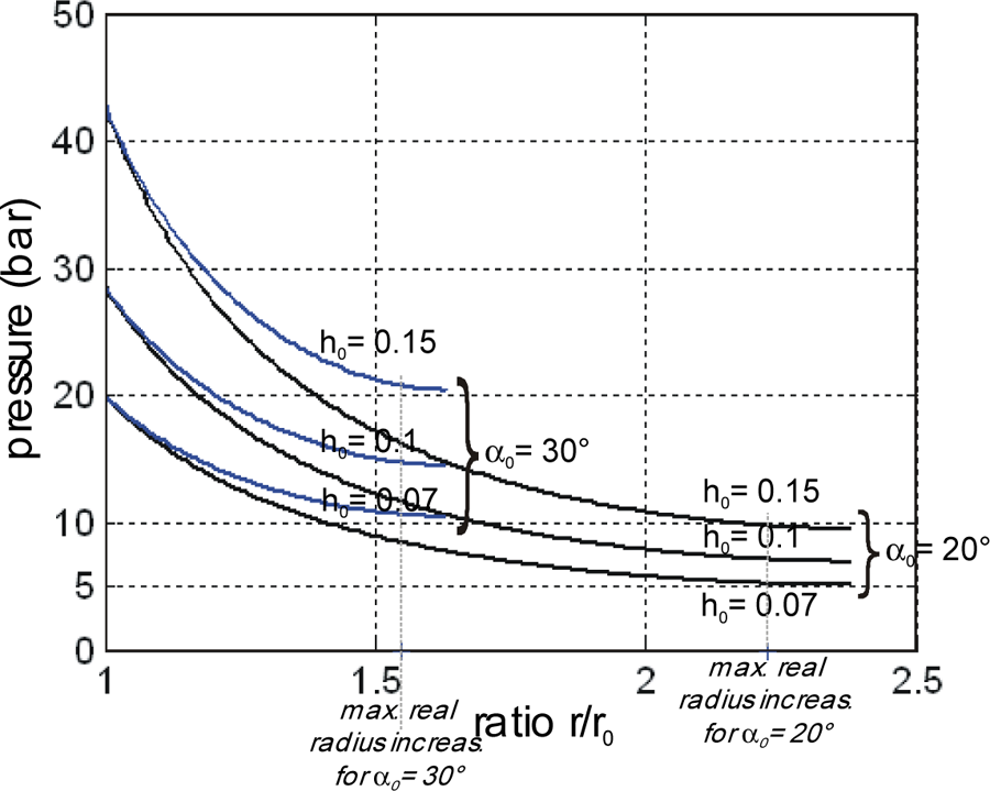
Maximum pressure estimated in the case of a thin-walled natural rubber inner tube McKibben muscle versus the contraction ratio for several cases of ratio initial thickness/initial radius and two cases of initial braid angles – the experimental maximum contraction ratios correspond to the recordings given in Figure 3.
There is a second source of ‘fragility’ in McKibben muscles due to its rubber-type material: its high sensitivity to environmental conditions and how it is used. In a classical rubber engineering thesis published during the golden age of rubber physics and technology research (Davey and Payne, 1964), a paragraph entitled ‘Useful Life’ reads as follows:
A question often asked by intending users of rubber is ‘How long will it last?’ Generally no precise answer is possible since much depends on service conditions. […] The life will, of course, always be shorter where the rubber is used as a thin film exposing a large surface to oxidation, or if there is exposure to light or heat, or if the rubber is under tension […] (page 16).
In a relatively recent paper, Klute and Hannaford (1998) tried to determine the ‘fatigue characteristics of McKibben artificial muscle actuators’ by using recent theories of mechanical fatigue claiming that ‘the mechanical fatigue in rubber materials is the result of slow crack growth during cyclic loading or deformation’ (p.1776). The fatigue limit for uniaxially loaded specimens, specified as a relationship between the growth of crack length per cycle and tearing energy of the considered rubber, is applied to the multi-axial case of the McKibben muscle by means of the contraction function of equation (9). Based on Mooney and Rivlin’s phenomenological theory (see following sections) and published fatigue limit data from rubber technology, the authors finally estimate the fatigue limit for McKibben actuators whose inner tube is made either of silicone or latex, as a function of an imposed maximum contraction ratio per cycle: in latex, for example, this cycle limit number varies between 4320 (εmax = 25%) and 17,620 (εmax = 5%). Such a detailed study is particularly interesting in emphasizing the high reliability that can be placed on the useful life of artificial muscles made of rubber-like materials given their working conditions, as this can be significant if McKibben muscles are used by antagonistic pairs in robotics, notably. Moreover, the Klute and Hannaford study highlights the advantage of natural rubber – that is, ‘soft’ rubber – in comparison to synthetic rubbers, which is a relatively expected result. However, let it be said that natural rubber is not an ideal choice given the permeability-to-gases criterion: butyl rubber (a copolymer of isobutylene and isoprene) would be a better type to respect this criterion with, moreover, an excellent resistance to oxidation, ozone attack and ageing; nevertheless they have poorer physical properties than those of natural rubber and, undoubtedly, a lower cycle limit number, in accordance with the Klute and Hannaford measurement. Let us finally note that the Klute and Hannaford study does not seem to have taken into account rubber inner-tube thickness, nevertheless, without us being able to assert that in so doing it would modify their estimates.
As a conclusion to this section devoted to the working principle of McKibben muscle, it appears, first, that the authors agree with the given expression of what can be called a force model of an ideal cylindrical McKibben artificial muscle, on the assumption of a zero-thickness inner tube. This expression, which can take several forms, is without a doubt, the fundamental force expression of the McKibben muscle since its invention in the 1960s. Taking the tube thickness into account is the first challenge in current McKibben muscle modelling studies. We have tried to show that, in the framework of thin-walled membranes theory, it is possible to derive an elementary real static force model close to the ideal one and to relate the surprising ballooning phenomenon peculiar to rubber physics to McKibben muscle theory. However, if this latter analysis justifies the working pressure range of McKibben artificial muscles, it also emphasizes the fundamental role of elasticity played in McKibben muscle physics and which, in our view, is not the subject today of enough research, particularly to determine if it is necessary or not to distinguish thin-walled from thick-walled McKibben muscles in relation to its working principle, which seems still to remain an open question.
Advanced static modelling of the McKibben muscle
All models presented in the ‘Working principle of the McKibben artificial muscle’ section, considered the McKibben artificial muscle as a pure cylinder. In fact, to make sense, this assumption would imply a continuous adaptation of tips to the artificial muscle radius variation. In practice, all current versions of these artificial muscles are designed with constant radius tips. A tip effect results, which we propose to study in the ‘Tip effects’ section, we then address in the sections ‘Elastic force and the question of the McKibben muscle as a fibre-reinforced rubber tube’ and ’Static friction and muscle hysteresis’, the questions of elastic and friction forces inside the McKibben muscle, and the consequences of a 100% non-cylindrical McKibben muscle shape on the static force model.
Tip effects
We show in Figure 10, a close-up of a McKibben muscle rayon-braided sheath tested in Figure 3(a): On the left-hand side, the middle cylindrical portion of the muscle and on the right-hand side, the muscle free extremity.
Close-up image of the braided sheath in its (a) middle cylindrical and (b) tip portions.
It is clear that both inner-tube rubber softness and braided-sheath flexibility make the working of McKibben muscles possible, transforming its initial cylindrical shape into a contracted complex spindle-like shape, which contributes in some ways to its biomimetism. Due also to a general, relatively dense pantograph network, the contracted McKibben muscle maintains a cylindrical shape with a comparatively large middle portion (Figure 10(a)), while its ‘flexible jointed’ braided sheath naturally adapts to the passage from boundary radius r0 at the tips to current radius r in the cylindrical portion (Figure 10(b)). In practice, a real cylindrical McKibben muscle is only a pure cylinder at zero contraction ratio. Is it possible to integrate these tip portions into the previous cylindrical model? A first and empirical method consists of stating that these non-cylindrical tip portions represent some end-effect peculiar to the real McKibben muscle, which induces a natural contraction loss with respect to the purely cylindrical artificial muscle, and which could be expressed by some empirical correction factor inside the cylindrical model; in our own article (Tondu and Lopez, 2000), we then proposed changing contraction ratio ε into a corrected contraction ratio kε, with a factor k constant or specified as a function of P, since the higher P is, the more obvious the tip effect. However, this approach is not suitable for explaining the specific effect of tip portions. Recently, Wereley’s team (2009) proposed ‘because it was observed during the experiments that the tips of the actuator were similar to a circular arc’ to consider a reduced muscle length – with our notations: l’ = l− 2(r−r0). Following the same idea, we propose to try underlining the effect of artificial muscle tip portions by approaching their shape to a conical form, as illustrated in Figure 11(a). Our purpose here is to first determine an ideal model – within the meaning of the previous paragraph – of this cylindrico-conical McKibben muscle and to compare its static force with the corresponding cylindrical model. To do so, we consider the following two assumptions:
Current length lc of each conical portion is proportional to contraction ratio ε as follows: lc = kcl0ε, where kc is a constant to be chosen between 0 and a maximum value so that
During contraction, the current position of the fixed tip along the muscle axial direction is denoted z, with
As was made in the case of the ideal cylindrical McKibben muscle, it is possible to apply the virtual work theorem to this three-portion model:
Let us consider a small positive variation δr of the artificial muscle radius in its middle portion
The two conical tips are symmetrical. Let us consider the fixed tip. The only working force is the lateral pressure force against the conical surface. From the well-known straight cone lateral-area formula, we can derive the elementary lateral formula of conical tip dAlat between z and z+dz: dAlat=π(2rz+ tan βdz)(dz/cos β). If we disregard the term in (dz)2, we obtain: dAlat= 2πrzdz/cosβ. When radius r of the middle portion increases by δr, current radius rz increases by δrz = δr(z/lc), and P pressure work versus this elementary surface is given by (see Figure 11) ‘PdAlatδrz cos β’, which can also be written as follows ‘2π[r0+ (r−r0)(z/lc)](z/lc)dzPδr’ to be integrated over the z range [0, lc] in order to determine total lateral pressure work finally equal to [πr0lc+ (2/3)π(r− r0)lc)]Pδr. This is also the expression of lateral pressure work at the free conical tip. There is additional axial pressure work to consider versus the free conical tip equal to
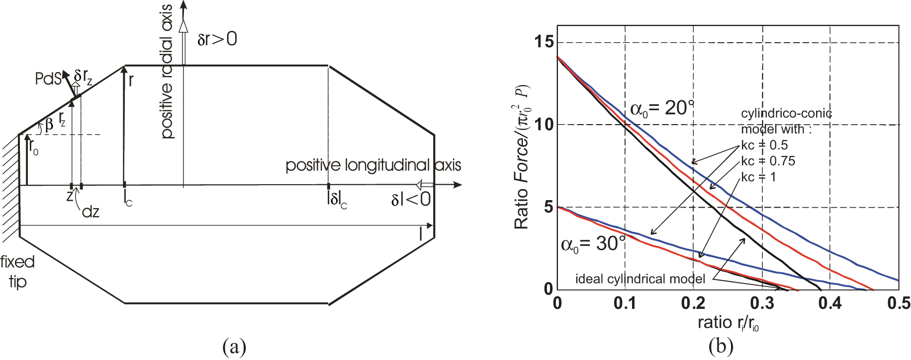
(a) Model of a cylindrico-conical ideal McKibben muscle whose conical tips have a length lc proportional to the artificial muscle contraction ratio by means of a constant factor kc and (b) comparison of the generated force with that of the ideal cylindrical model.
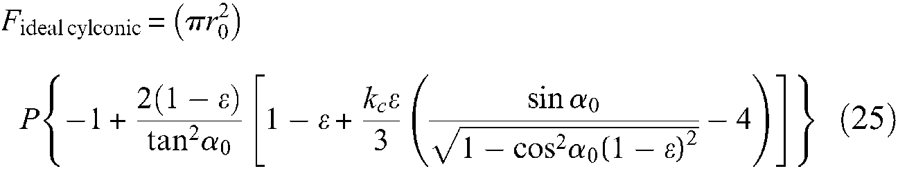
These works must be counterbalanced by the work of the contraction force positively denoted Fideal cylconic, which in the case of our (δr,δl) notation is equal to Fideal cylconicδl. We derive:
We show in Figure 11(b), a comparison between
Elastic force and the question of the McKibben muscle as a fibre-reinforced rubber tube
In his famous technical document describing the symbolic expression of McKibben static force, Schulte (1961) takes into account a loss of elastic energy; he writes it up as follows – using our notations, but maintaining notation ke, introduced by the author to designate an elastic constant assumed to be identical in the circumferential direction as in the longitudinal direction:
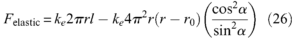
The first term of this expression would correspond to the longitudinal elastic force, while the second term to the circumferential elastic force transformed into a longitudinal component due to the braided sheath – its computation can easily be derived from equations given in the ‘Notion of artificial muscle’ section. These expressions are clearly related to a linear approach to inner-tube elasticity. However, beyond the limit of this linear elasticity assumption, this elastic force expression is highly questionable since it was established without taking into account inner-tube thickness. We believe that the elastic force, as opposed to the pressure-produced force, is more accurately determined from a theory of elasticity considering the inner tube as an incompressible solid. Let us first assume a cylindrical shape during full contraction. An initial way to determine this elastic force can consist of applying rubber-elasticity statistical theory, which has already been considered. In the framework of a thin-walled inner tube, we immediately derive the following expression from equation (22), to which we gave a negative sign since it is opposed to the contraction force:

and thus:
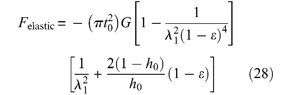
where λ1 is given by equation (23). In Figure 12, we show a simulation of this elastic force in the case of the α0 = 20°, and for three cases of t0 thickness (in cm): 0.05, 0.1 and 0.15 – corresponding to a same value h0 ratio for r0 = 1 cm, as well as for two of shear modulus G: 0.54 and 1.37 MN/m2.
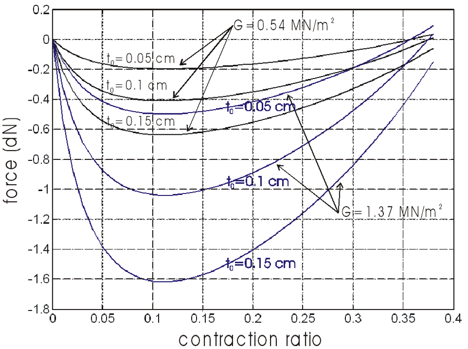
Evaluation of elastic force versus contraction ratio in the case of a cylindrical McKibben muscle with a 20°-braid initial angle and a thin-walled inner tube characterized by its thickness t0 and its shear modulus G.
The elastic force appears to be maximum for a contraction ratio close to 0.1, but in any case and even for relatively ‘hard’ rubber, the resistive force due to rubber elasticity appears to be relatively weak in comparison with the active force that the McKibben muscle is able to develop. It would, however, be necessary to confirm this kind of result with thick-walled inner tubes – typically h0 = 0.3. It is also important to note that, in our view, and as it seems to be in accordance with the theoretical model of equation (21) or further equation (31), no circumferential elastic force has to be added to this first component.
If Treloar’s statistical approach is particularly interesting for estimating ballooning or elastic effects, a more general approach, and perhaps a more accurate one, consists in using the Mooney and Rivlin’s phenomenological approach based on a stored energy function W, which is a function of two strain invariants I1 and I2 as follows:
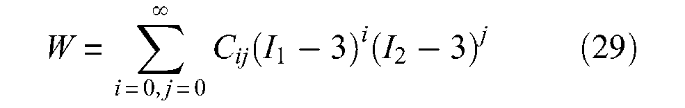
where Cij are empirical constants. Invariants I1 and I2 can be expressed in terms of main extension ratios λ1, λ2 and λ3 at the point of the deformed body by formulae:

is a valid one. As far back as 1940s, Mooney (1940) showed that this expression is also valid for large deformations of an ideal incompressible, highly elastic material. Based on this Mooney form, the following stress–strain relationships are derived by Rivlin and Saunders (1951):
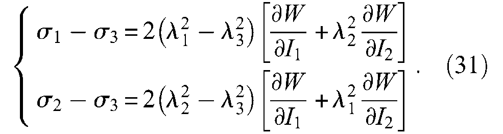
In the case of a thin-walled cylinder,
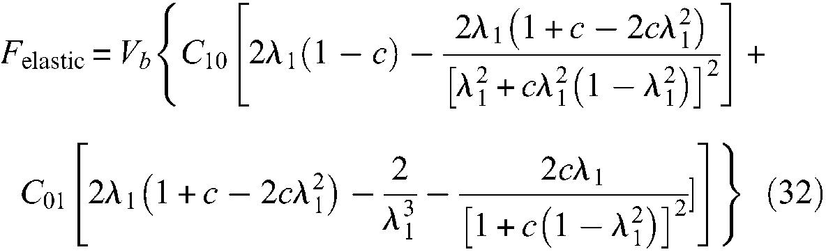
where Vb is the inner tube volume, which is constant in the case of the thin-walled assumption, and c = (l0/2πr0N)2. This approach leads, in the case of the Chou and Hannaford experiment, to an estimate of elastic force of about 20 dN for a control pressure of 5 bar and in a large λ1 range, with a prototype in natural latex characterized by the following parameters: B = 27.7 cm, N = 1.5, l0 = 26.4 cm, r0 = 0.87 cm, so that
More generally, we are of the opinion that a more detailed analysis of compared elastic-force modelling between statistical and phenomenological approaches for thin- and thick-walled rubber tubes in McKibben muscles is still lacking. However, within this open framework, the recent Liu and Rahn (2003) study could appear as an original means of definitively solving the problem by re-situating the static McKibben modelling problem in the more general context of fibre-reinforced elastic tubes. In the abstract of their article, the authors claim that ‘the calculated longitudinal strain and radius change match experimental results to within 5%’ (Liu and Rahn, 2003: 853). First, although not clearly stated in the article, but in accordance with Figure 1 of this same work (p.854), only a real cylindrical model of the McKibben muscle seems to have been considered. Second, no friction model seems to be integrated into the model, whereas Festo’s (2001) technical documents clearly show the existence of braided-sheath friction even when it is included inside the rubber tube. By using the assumption of inextensible strands in the weave and within the framework of Mooney and Rivlin’s large strain theory applied in the general case of a walled tube with a standard polar coordinate system similar to the one previously mentioned, the authors derive complex symbolic expressions of azimuthal and axial stresses as a function of the current braid α angle. However, because the authors do not deduce a static force expression of McKibben muscle from these stress-expressions, it is not easy to compare this particularly relevant approach with the results achieved until now from the mechanical approach initiated by Gaylord and Schulte. We consider that this comparison is still lacking in the field of McKibben muscle studies.
In any event, in the case of a force balance analysis transmitted by the inner tube as in the large-strain approach, including the weave as an inner-tube reinforcement, the question of friction remains and requires a separate analysis.
Static friction and muscle hysteresis
Let us start again from Schulte’s model. According to this model, total static friction force denoted Fstatic friction would take the following form – in absolute value and with our own notations:

where fs and fst are according to Schulte (1961), the ‘coefficients of friction between the strands of the helical sleeve’ and the ‘coefficient of friction between the strands of the sleeving and the inner tube’, respectively (p.95). This model assumes two things:
The contact surface to take into account is the full current cylindrical surface (2πrl).
The internal friction of the McKibben muscle would result from a double phenomenon: strand-on-strand friction and strand-on-inner tube friction.
Let us disregard, for the moment, the question of the conical tips so as to limit our analysis to the purely cylindrical McKibben muscle model. It is clear that the previous first affirmation is erroneous for two reasons. First, strand-on-strand or strand-on-inner tube contact surface cannot exceed 2πr0l0, if an initial full covering of the inner tube is assumed, that is, in the muscle resting state with the complementary assumption of a flat strand-on-strand contact, as illustrated in Figure 13(a). However, when angle α changes, the expression of the contact surface can be easily derived from a single geometrical analysis, illustrated in Figure 13(b): The hachured elementary contact pantograph shown in Figure 13(a) has a surface
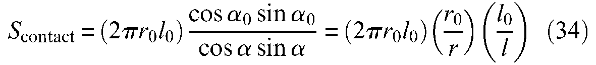
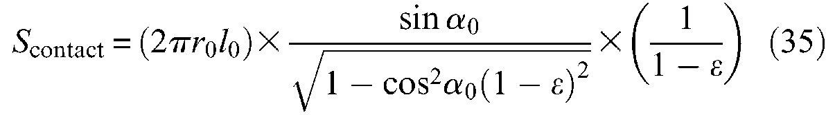
and with respect to the contraction ratio ε, we obtain:
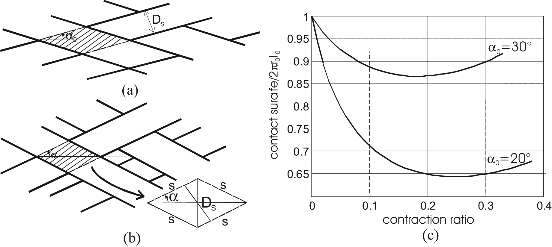
Determination of braid-on-braid surface contact in the case of a cylindrical McKibben muscle with the assumption of flat strands initially fully covering the artificial muscle exterior surface: (a) initial elementary pantograph, (b) current elementary pantograph and (c) development of total contact surface versus contraction ratio in two cases of initial braid angles.
A similar expression is proposed by Davis and Caldwell (2006). We show in Figure 13(c) curve Scontact(ε) for the two values of α0 = 20° and 30°; in both cases, the curve abruptly decreases just after α = α0 but increases again after α = 45° or
The higher l0, the wider the contact surface and thus static friction force. As a result, static friction introduces a l0 dependence in the purely cylindrical McKibben muscle model, which was not present in the force-model without friction.
The higher α0, the wider the contact surface. Therefore, it is preferable to select low initial braid angles.
What is the effect of conical tips in the determination of this contact surface? Let us consider the notations introduced earlier, and the conical tip defined for
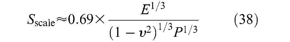
Moreover, there is another factor to take into account in the determination of contact surface: the shape of the strand defining the real contact surface. Generally – this is, however, not perfectly true in the case of twisted strands – strands have a cylindrical shape and, as a result, the real strand-on-strand contact surface cannot be directly assimilated to the apparent contact surface determined, as strands were flat (Figure 14(a)). One possible way of dealing with this problem consists of considering that due to elastic deformation between strands, only a limited portion of the apparent contact surface is really in contact. Let us call (1/Sscale) this ‘correction factor’, leading to the following model of the friction force inside the braid noted Fbraid static friction– the expression is given in absolute value since it changes signs with velocity as a function of contraction (negative sign) or elongation (positive sign):

where fs is the static friction coefficient already considered, and Scontact the total apparent strand-on-strand contact surface determined as strands were flat, and whose previous expression of equation (35) is a model in the case of a pure cylindrically shaped McKibben muscle. Davis and Caldwell (2006) were the first – to our knowledge – to consider Hertz’s contact theory for estimating the real contact surface between strands and subsequently the scale factor. They propose an original and elegant approach based on one of the famous results of Hertz’s contact theory, the estimate of the contact area between two elastic spheres – see, for example, in Stolarski (1999) – as illustrated in Figure 14(b). In the case of a cylindrical model of the McKibben muscle, we determined the apparent – or flat – contact between two strands by the elementary pantograph of Figure 13(a) and (b); this area varies between
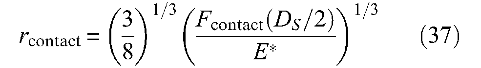
with
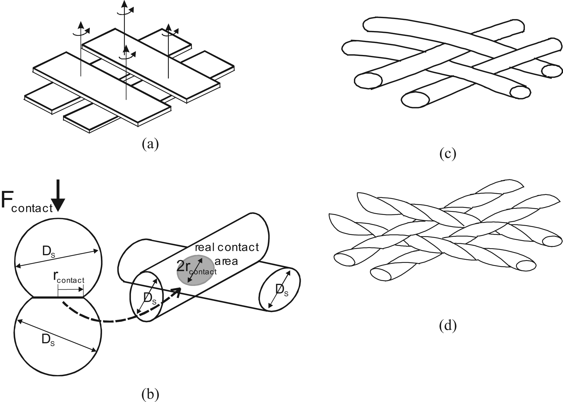
Contact analysis between strands of McKibben braided sheath: (a) interpretation of the braided sheath as flat-on-flat solids, (b) determination of the real contact between two cylindrical strands such as an elastic contact between two identical spheres in Hertz’s contact theory framework, (c) braided nature of the McKibben muscle pantograph network whose rotation movements are made without solid axes by comparison with (a) and (d) typical scheme of a twisted strand highlighting its specificity in comparison to a strand modelled by a cylinder.
The authors finally suggest defining the scale factor as the ratio: Sscale = (DS/2rcontact), and whose the expression can be written as follows: 7
Although obtained with restricted assumptions, the authors show the relevance of the approach to experimentally estimate the quasi-static friction in McKibben muscle interpreted as the sole cause of hysteresis – see this latter point later on. Recently, this model was criticized by Doumit et al. (2009), but their own model of two crossing strands like two parallel cylinders (their Figure 11, p.1287) is questionable. Beyond the question of the best elastic contact model to apply to double-helix McKibben braided sheath, a nagging question remains: how to integrate it to the complex shape change at the conical tips whose modelling friction part – non-negligible, as already emphasized – combines the difficulty of an accurate application of Hertz’s theory to the strands belonging to an apparent contact surface, all the more difficult to determine given that the concerned contact surface has a conical-like shape changing with contraction ratio? Finally, we are far from Schulte’s simple friction model without the assurance of being able to exhibit an accurate weave-friction model.
There is another question in relation to Schulte’s model: is there friction between strands and the rubber inner tube? Although some authors still seem to assume so – see, for example, Figure 3 in the very recent article by H Van Brussel and his team (Vo-Minh et al., 2011) – we are of the opinion that the answer is clearly negative. According to Rabinowicz (1968), ‘dry friction is the resistance to motion which exists when a dry, solid object is moved tangentially with respect to the surface of another which it touches or when an attempt is made to produce some motion’ (Chapter 1, pp.1–3). Strands can slip against strands due to the force transmitted to them by the inner tube, but strands cannot slip against the inner tube because there is no other acting force. In fact, the McKibben working principle explained in the ‘Notion of artificial muscle’ section depends, in practice, on a friction problem: the friction coefficient between strands and rubber inner tube is greater than that between strands and strands and, as a result, due to the high static rubber friction coefficient, strands stick against the inner tube, while strands slip on strands. In addition, because braided sheath is like a ‘flexible jointed structure’, it can adapt itself to the shape constraint imposed by the constant radius muscle ends: far from the tips, the braided sleeve attached to the inner tube opens itself according to the pantograph network law given in the ‘Notion of artificial muscle’ section; at the tips, a certain portion of the braided weave no longer follows this law, but strands always slip on strands generating a transition between radius tip and current radius r thanks to the double fact that strands can, to a certain extent, move freely onto their neighbours and that the part of the strands that are not in contact with other strands are sealed to the rubber tube.
In the above mentioned article by Van Brussel’s team, the authors consider four possible causes of hysteresis: ‘ (a) cord friction, (b) cords and bladder friction, (c) conical deformation and (d) bladder stretching due to volume increasing’ (Vo-Minh et al., 2011: 179). We have already eliminated the second source of static friction in this schema. It seems also very difficult to consider that conical deformation is a source of hysteresis since, as noted, this deformation results from a certain sliding mode of strands over strands and so no new physical phenomenon can be associated with this conical deformation. Bladder stretching can effectively cause hysteresis due to peculiar rubber contraction–elongation hysteresis. This phenomenon obviously depends on rubber inner-tube dimensions; however, we postulate that – and particularly for thin-walled inner tubes – it is weak in regard to braid-on-braid static friction. Another source of hysteresis could be strand stretching. This problem was tackled by Caldwell’s team (2003). In the framework of standard linear elasticity applied to a braid strand – Young’s nylon modulus is considered in their study – the authors distinguish two forces ‘separately [contributing] to the strand extension’: ‘the contractile force which is acting parallel with the strands’ and the ‘radial force’ determined from hoop stress derived from thin-walled cylindrical tube theory (p.219). They, therefore, determine a formula for ‘the length [b] of one braid strand […] given by: b = bmin+δblong+δbrad’ (p.220) where bmin is the rest length, δblong and δbrad are the extension caused by longitudinal and radial forces, respectively. However, beyond the relevance of this approach, it is important to note that the hypothesis of an extensible braided sheath completely transforms the notion of McKibben muscle since, as we attempted to illustrate in Figure 5, the working principle of cylindrical McKibben muscles assumes non-stretchable strands in order to maintain the side length of each elementary pantograph constant. Extensible strands will lead to abandoning this principle and the fundamental force model of equation (10). In some ways, we can say that a good McKibben muscle must be designed so as to be able to fulfil the assumption of a non-stretchable sheath; this is made easier particularly thanks to the possibility of considering multiple yarn-strands without violating the fundamental force model, as previously noted.
In the framework of our search for hysteresis causes in McKibben muscle contraction–elongation, we can conclude – in agreement with Chou and Hannaford (1996) – that the main cause of hysteresis in this artificial muscle is strand-on-strand friction and thus we consider it is possible to write the expression of static friction force Fstatic friction in McKibben muscles as follows:

An important point, however, in our view, must be emphasized from this conclusion. If we integrate the scale-factor of equation (38) into the braid-friction model of equation (36) we derive a static friction force expression proportional to P4/3, which is ultimately not in accordance with the standard theory of solid-dry friction, assuming a friction force proportional to P. Moreover, if we now look at the numerous studies showing McKibben muscle characteristics with hysteresis, it clearly appears that hysteresis width between contraction and elongation is not proportional to P: see, for example, Bridgestone Corporation’s (1987) technical documents exhibiting hysteresis cycles whose width barely increases with P, or certain curves given in Chou and Hannaford’s study (1996) in which the hysteresis cycle seems to be independent of P or even larger for low values of P (Figure 3, p.93). From our own results of Figure 3, we obtain, for example, in the case α0 = 20°, at a contraction of 0.1 – to limit the tip effect – the following ratios between hysteresis widths corresponding, respectively, to 2, 3, 4, 5 bar with respect to a 1 bar hysteresis cycle width: 1.7, 2.3, 2.6, 3 whereas 2, 3, 4, 5 were expected. These former values can be approached by 20.75, 30.75, 40.7and 50.7, respectively. This quick analysis suggests a friction dependence lower than P, and it may be that the approach for dealing with friction in McKibben muscles since solid friction theory as written in equation (36), is not the correct way. In fact, we consider that the textile nature of McKibben muscles has not been emphasized enough: the physical model of the braided weave seems to us better illustrated by Figure 14(c) or by Figure 14(d) in the case of twisted strands, than by Figure 14(a) even if an examination of the real contact surface as shown in Figure 14(b) is made.
Now, as emphasized by Rubenstein (1958/1959) in an old, but still relevant, study: ‘it has been known for a considerable time, that textile materials do not obey Amonton’s laws of friction’ (p.297). The term ‘textile materials’ designates yarns and fibres of various materials but also strands made of yarns, and it is clear that braided weaves made of rayon or nylon strands are textile materials. Among properties characterizing the friction coefficient of textile materials, two could be particularly important for a better understanding of the static and dynamic properties of the McKibben muscle (Rubenstein, 1958/1959):
Friction coefficient increases with decreasing pressure.
Friction coefficient increases with increases in velocity.
The importance of the second property will be seen in the next paragraph. The first property is believed to explain the non-proportionality of the hysteresis cycle to P; this can be expressed in different ways as emphasized by Howell et al. (1959: 32−33) among which the following relationship is considered as the most relevant:

where L is the normal load and coefficients C and β are dependent on the geometrical configuration of the contacting surface, with β < 1. As written by Howell et al.:
All workers in the fibre-friction field who adopt this relationship have assumed: (i) that friction arises from adhesion at the points of real contact, and (ii) that junctions at the interface have a constant shear strength. Consequently, they have all explained the variation of [friction force] with [load] in terms of the variation of the true contact with [load] (Howell et al., 1959: 33).
This clearly indicates that this friction model can be thus linked to Hertz’s contact theory, but undoubtedly differently than reported in this review. The experimental use of equation (40) leads to a large range of β values, for example, experiments with crossed fibres at right angles with loads from 0.3 to 400 mg lead to a value β = 0.8 for drawn nylon, 0.9 for undrawn nylon and 0.96 for cellulose acetate (Howell et al., 1959: 33). The very rapid estimate of a β = 0.70−0.75 was made in the case of our rayon twisted strands weave and these references lead to considering that static-friction modelling in McKibben muscles could gain a great advantage from the huge literature on textile friction.
Beyond the relevance of applying textile physics to static-friction modelling in McKibben muscles, it is our opinion that textile engineering can provide interesting information for weave design. For example, still bearing in mind Rubenstein’s article, ‘the frictional force was found to increase with increase in specimen diameter’ (1958/1959: 300), which would suggest favouring small diameter strands. However, as we try to show in the following paragraph, a reduction of frictional phenomena inside the weave is not always relevant from a purely biomimetic point of view.
Dynamic modelling of the McKibben muscle
Why a dynamic modelling of the McKibben muscle?
Rigorously speaking, the modelling of an actuator is essentially static, the possible damping factors being generally considered as exterior entities. It is, however, obvious that kinetic friction must be taken into account as proposed in Doumit et al. (2009) but in the framework of solid-friction theory, this kinetic friction is quasi-constant and, therefore, by adding a kinetic friction to the static model, the actuator model could be complete without needing further dynamic experiments. The case of fluidic actuators is, however, particular due to the high dependence of actuator dynamic behaviour on the device supplying it with fluid. Theoretically, McKibben muscles can be either hydraulic or pneumatic. However, the hydraulic version is difficult to put into work due to high fluid consumption induced by volume increase, while in its gas version, the consumed gas can be directly evacuated in the room through the control pneumatic device. In the framework of this review, we will not tackle problems associated with the use of servo-valves or intensity or tension/pressure converters, and their modelling, however important they are in the control of McKibben muscle actuators. On this subject see, for example, among the numerous articles on control of McKibben muscle actuators especially for robotics, Caldwell et al. (1995), Colbrunn et al. (2001), Tondu and Lopez (2000), Van Der Linde (1999), Van Der Smagt et al. (1996) and Zhu et al. (2008). Generally, it can be said that the servo-valve or pressure transducer, introduces a non-linear component into the actuator chain due to the fact that the control variable is a pressure inside a bladder whose volume changes with contraction ratio: as a consequence the dynamic behavior of the set servo-valve and artificial muscle depends on the muscle size and more particularly on its geometric parameters l0, r0, a0’.
If we disregard the modelling of the pneumatic component feeding the McKibben muscle there are still two reasons for considering a dynamic modelling of the artificial muscle:
First, if we assume a textile material-approach to the friction problem, it is clear that load velocity variation must be taken into account;
Second, from a biomimetic point of view, the dynamic behaviour of McKibben muscle versus loads and gravity is known to be an estimate of the scope of its biomimetic behaviour.
We are trying to show that these two points can be connected. To introduce our approach, let us consider Figure 15: two sets of pressure step responses generated in open-loop are shown with various loads in the same pneumatic control conditions, but with two different types of braids. It is clear that the dynamic responses are very different. In the case of a rayon-made braid, the McKibben muscle exhibits no overshooting (Figure 15(a)) whatever the load, while for an iron-made braid it exhibits an overshooting for all loads (Figure 15(b)). In terms of control, these results are particularly interesting because they suggest that the actuator chain, including McKibben artificial muscles, and its pneumatic device could be identified in open-loop as a second-order whose parameters depend on the muscle and its functioning conditions, and can be used as a model for a closed-loop control. But these results also underline the great importance of braid materials in the muscle dynamic response.
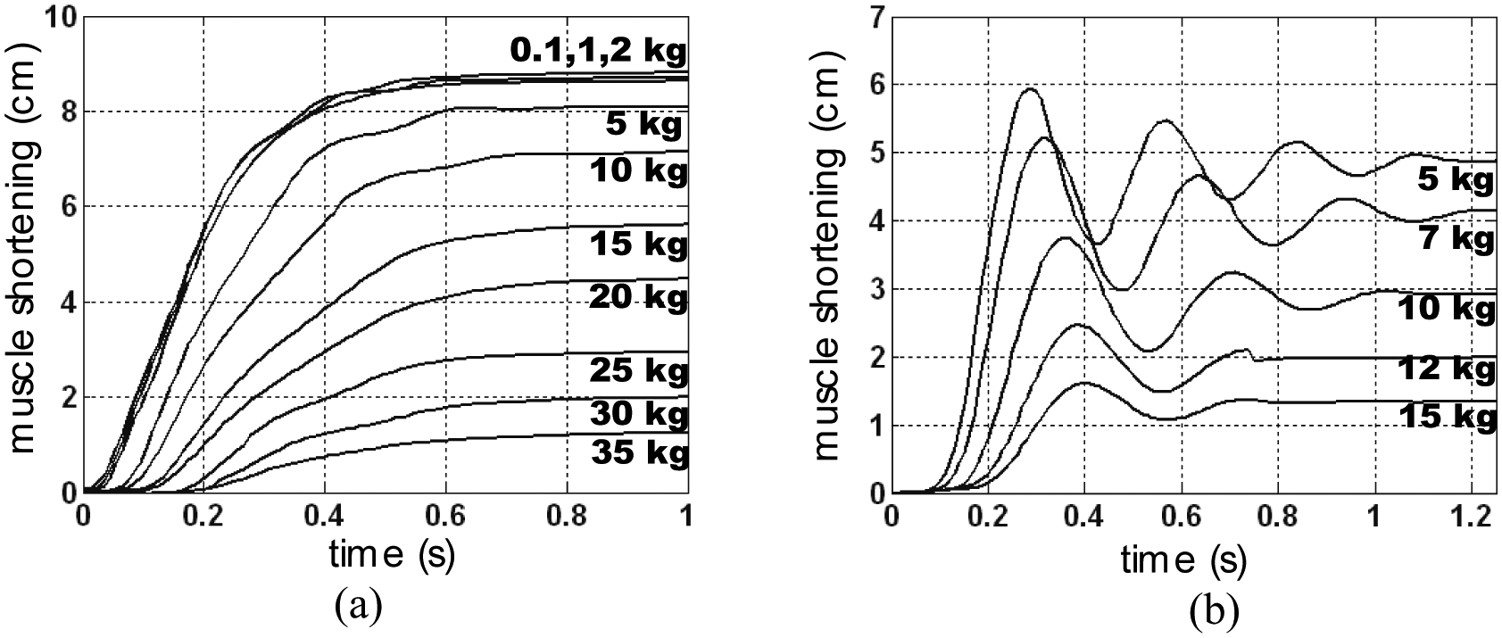
Typical open-loop step-response for two cases of McKibben muscles in free after-loaded conditions: (a) muscle braided with twisted rayon strands and (b) muscle braided with iron strands.
This is the phenomenon we propose to characterize by applying a biomimetic approach to the McKibben muscle inspired by Hill’s well-known experiments, and which offers the great advantage of making the dynamic analysis practically independent of pneumatic control devices.
Hill-like dynamic behaviour of the McKibben muscle
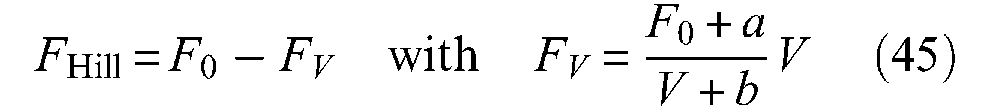
Let us consider a single McKibben muscle driving a load denoted M against gravity and let us denote x the current position of the artificial muscle, defined as: x = l0−l = l0ε. The equation of the dynamic contraction is read as follows by Reynolds et al. (2003):

where K is a spring coefficient, B is a damping factor and Fce is the ‘effective force provided by the contractile element’ (p.312). This approach is motivated, according to the authors, by a Voight-type three-element model of the pneumatic muscle composed of three parallel components: spring element K, damping element B and contractile element Fce (see Figure 1 of the same article). The experimental determination of B and K is made by a ‘bellringer’-type perturbation approach wherein the load is suddenly reduced at constant pressure, while x-time history is recorded. By this means, B, K and Fce can be estimated as an affine function of P. This approach, however, has the disadvantage of developing the dynamic study of McKibben muscles independent of its static modelling by splitting components B, K and Fce. An alternative approach could consist of writing the dynamic McKibben contraction equation as follows:

where Fdyn is the dynamic force produced by the artificial muscle and which differs from the previous model only by an assumed viscous-type friction component. In some ways, the K and B elements of Reynold et al.’s model are now integrated into Fdyn. While the static modelling of the McKibben muscle was essentially analytical, its dynamic modelling, as emphasized at the beginning of this paragraph, can also be inspired by phenomenological approaches peculiar to natural skeletal muscle. Among them, the so-called Hill model can be particularly interesting due to both its simplicity and its universality since it characterizes globally and, particularly relevantly, the phenomenological behaviour of any animal skeletal muscle. Hill’s (1938) equation is generally presented as the relationship between muscle shortening velocity V and its corresponding tension that we will denote here FHill so as to distinguish it from Fdyn: 8

where F0 is the maximum isometric contraction force, that is, static force at zero contraction ratio, a is a constant having the dimension of force and b is a constant having the dimension of velocity. When tension FHill is equal to 0, shortening velocity is at maximum and is given by Vmax = F0b/a. It is then possible to derive a normalized form of Hill’s equation as follows:
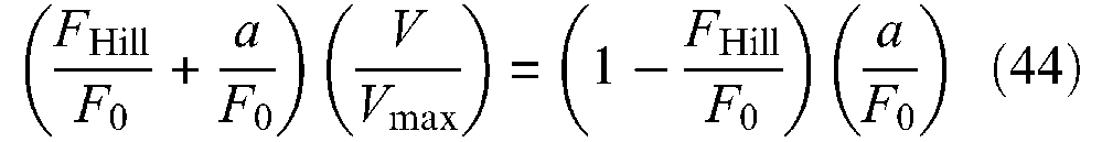
The shape of the rectangular hyperbola characterizing Hill’s curve with asymptotes at –a and –b is thus entirely determined by constant (a/F0) = (b/Vmax). To avoid any confusion, we believe it useful to recall the experimental conditions in which the Hill equation was determined. A misinterpretation of the force component in the Hill formula could indeed explain the surprising conclusion given by Klute et al. (2002) with nylon-braided McKibben muscles:
Measuring the output force under constant velocity conditions while maintaining constant pressure over the actuator’s working length, we found the output force to be a function of length but not a function of velocity. […] The results show the actuator has only a small amount of natural damping as output force decreases slightly with increases in velocity. At maximum contraction velocity, the output force decreases by only 6% while biological muscle decreases to zero output force (p.301).
The Hill model is a macroscopic muscle model consisting of a series of elastic elements (SE) and a contractile element (CC), as illustrated in Figure 16(b). It is essentially associated with the notion of isotonic contraction of the muscle lifting up a given weight: Force FHill does not therefore designate an ‘instantaneous force’ as written in Klute et al. (1999: 222) but a tension experimentally imposed on the muscle by a load. Similarly, velocity V must be understood as a ‘steady-state value of velocity reached, corresponding to a given load’ (Lubin, 1959: 1881). We deduce the link between the general dynamic model of equation (42) and Hill’s equation: During the constant velocity steady state, we obtain
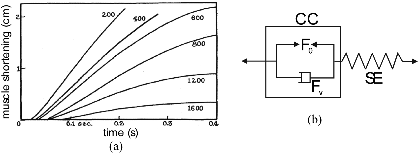
(a) Typical dynamic response of skeletal muscle for various neural activations in free post-loaded conditions in standard Fenn and Marsh (1935) and (b) proposed symbolic Hill model to express the natural damping character of skeletal muscle dynamic contraction.
To determine this tension–velocity curve, in his renowned 1938 paper, Hill proposed what is called an isotonic quick-release test: the muscle maintained at a constant length l0 is stimulated until it attains its isometric contraction force F0; a lower force FHill is then abruptly applied to the muscle in the form of a given load –‘post-load’ mode – causing muscle contraction. The two phases of the isotonic quick-release test then highlight the two components of the Hill model separately:
The first phase of an almost instantaneous shortening of the muscle brings SE elements into play: if initially the muscle shortens by –Δl, the stiffness of the SE element is, as a result, equal to (F0–Mg)/Δl;
After this initial response, the muscle proceeds to shorten for certain times at almost constant speed V: SE is no longer active, only CC is. The Hill equation, deduced from an energy analysis of muscle heat production, therefore expresses, in consequence, the dynamic behaviour of the CC.
Hill’s model leads to a particularly intelligent interpretation of the muscle contractile element; the Hill equation can indeed be written as follows:
During constant contraction–velocity phase, the dynamic force generated by the contractile element of the natural or artificial muscle thus appears as the sum of a contractile force F0 and a non-linear viscous component FV, function of V, as symbolized in Figure 16(b). To the best of our knowledge, Dillmann’s team was the first to underline the possibility of using quick-release for a dynamic model of McKibben muscles (Kerscher et al., 2005). In Figure 17(a), we show our own experimental set-up for performing a quick-release of a McKibben muscle: a manually controlled magnet is used to maintain a load M, while pressure is imposed to be constantly equal in further reported experiments to 5 bar; the magnet force is abruptly relaxed to generate the ‘quick release’. The steady state velocity phase is deduced from the position recording, and the corresponding value of V is determined (see Figure 17(b)).
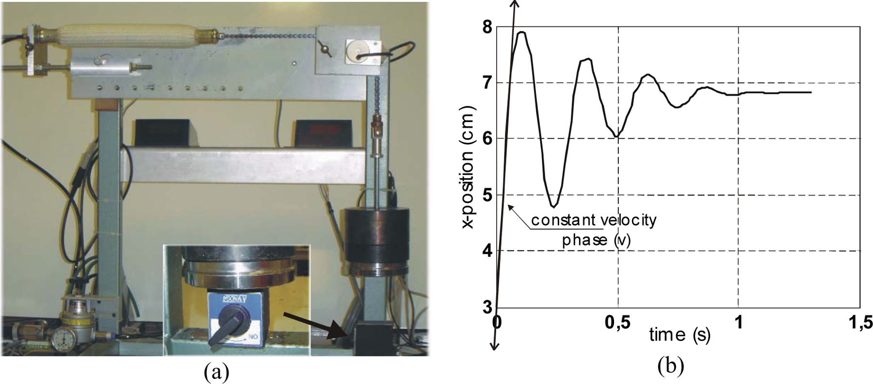
Quick-release experiment applied to the McKibben muscle: (a) experimental set-up – the magnet is shown in the central close-up – after pressure was established inside the muscle, the magnet is manually relaxed in order to perform the quick-release and (b) typical recording of artificial muscle contraction and estimate of velocity V.
Let us note an important point: quick-release allows splitting servo-valve behaviour from dynamic muscle behaviour; however, in the case of McKibben muscles, the increasing of muscle volume during contraction can induce weak variations around the imposed constant pressure, that we will consider to be negligible. We have shown in Figure 18, the experimental results obtained for the two different types of muscles already distinguished in Figure 15: Figure 18(a) shows the velocity–load diagram corresponding to an artificial muscle braided with twisted rayon strands identical to those shown in Figure 10, while Figure 18(b) shows the velocity–load diagram obtained in the same experimental conditions with iron strands made of 6 parallel 0.25 cylindrical yarns. 9
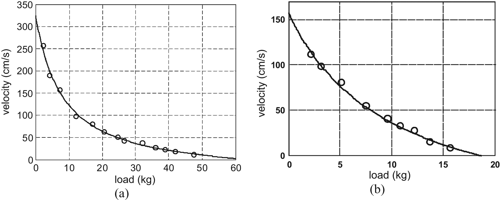
Velocity–load relationship established in quick-release experimental conditions for two types of McKibben muscles (circles correspond to recorded points with Figure 17 experimental set-up) and identification with a Hill model (full line): (a) case of a rayon-braided McKibben muscle and (b) case of an iron-braided McKibben muscle.
The recording points in the ‘rayon case’ can be located with very good accuracy on a hyperbolic Hill-type curve with the following parameters:

In their study of biomimetism in McKibben muscles, Klute et al. (2002) deduce identical ranges for (a/F0) estimated at [0.12−0.4] from a huge range of literature on animal and human physiology. According to the same authors, the lower value of 0.12 we obtained for our own rayon-braided McKibben muscle is believed to correspond to the Triceps Surae (Hof and Van Der Berg, 1981). Although, as mentioned by these authors, upper estimates for the same muscle are given in other physiological studies, this concordance emphasizes the possible biomimetism of McKibben muscles with a typical human skeletal muscle involved in daily life and sporting activities. A similar hyperbolic velocity–load curve was obtained by Dillman’s team (2005) with Festo muscles (Figure 12 of the cited article), although no corresponding (a/F0) ratio was provided by the authors. In Kerscher et al. (2006), the same authors present a normalized (FHill/F0) − (V/Vmax) curve for different control pressures, and clearly exhibit a near non-correlation of the hyperbolic experimental curve with pressure, that is, a characterization of the a and b parameters peculiar to artificial muscles, in Hill’s equation.
Let us now consider the Figure 18(b) velocity–load curve corresponding to our iron-braided weave. The real points can be approximately placed on a hyperbolic curve with a relatively flat curvature characterized by a ratio (a/F0) equal to about 0.54. This value is out of the large range considered by Klute et al. (2002). The comparison between the two experimentally tested extreme cases – the rayon-twisted fibre weave, and the iron-thin cable weave – clearly shows that McKibben muscles by means of a certain choice of weave material can exhibit a wide range of velocity–load curvature corresponding to a more or less viscous dynamic behaviour. This relatively positive accordance or non-accordance of a certain type of McKibben artificial muscle with Hill’s model – deprived, however, of any series elastic component since there is no passive spring-like element in the artificial muscle – can also be verified, by comparison between step-responses of the artificial muscle, with corresponding constant neural activation of the skeletal muscle, as can be seen in Figures 15 and 16. In Figure 15(a), the rayon-braided McKibben muscle exhibits the same natural adaptation to load variation as the skeletal muscle shown in Figure 16(a): whatever the load, the McKibben step-response never overshoots its steady-state position, and its response time only varies between about 0.5 and 0.7s for 0.1 to 35 kg load variations. Conversely, and although the servo-valve introduces a supplementary damping factor by comparison with quick-release experiments, the step-response of the iron-braided muscle is largely oscillatory with a number of oscillations and magnitudes depending on load.
We propose to examine later how this braid-material dependence of McKibben muscle dynamic performance could be explained by textile physics.
Role of textile friction in the dynamic biomimetism of McKibben muscle
The reported quick-release experiments were performed at constant pressure representing the neural activation level. Therefore, they are not concerned with the possible friction coefficient pressure–dependence effect discussed in the ‘Static friction and muscle hysteresis’ section. But these experiments are concerned by the potential velocity-dependence of the kinetic friction coefficient. Let us consider a constant kinetic friction denoted fv and the simplified linear static model of the artificial muscle force F considered in equation (1) in which the friction force component is equal to
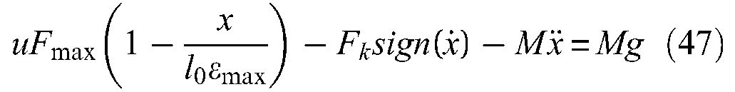
In quick-release conditions, the u-control is supposed to be constant in analogy with the assumption of a constant neural activation level in corresponding physiological experiments, and so Hill’s curve isometric force is now equal to uFmax; moreover, for
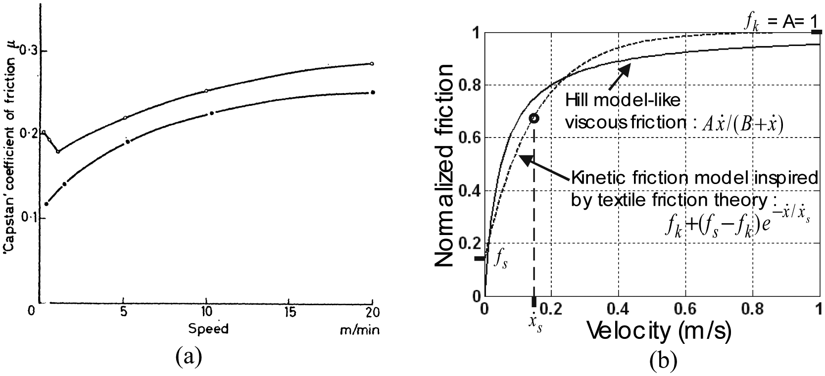
Attempts to interpret Hill’s model-like viscous dynamic behaviour of McKibben artificial muscles with textile braided sheath within the framework of textile friction: (a) typical variation of friction coefficient rayon fibre over rayon fibre with speed (from Röder (1953), reproduced in Howell et al. (1959: 68) – see text) and (b) comparison between a kinetic friction model inspired by textile physics and the non-linear viscous friction model derived from Hill’s model.
Inspired by the lower curve in Figure 19(a), we proposed (Tondu and Lopez, 2000) the following model for velocity-dependent kinetic friction braid-on-braid:

where fs is the static coefficient, fk is a limit coefficient for
Conclusion
McKibben muscle technology is clearly related to innovations in rubber technology, re-enforced hose and tyre design developed in the 1950s. In some ways, a McKibben muscle is like a tyre prior to bending whose initial braided angle is chosen sufficiently low to make possible the conversion of interior rubber-tube circumferential stress into an axial contraction force. A simple force analysis leads to a fundamental static force–equation in the form of
As an elastomeric structure, the transmission of pressure forces through the inner tube thickness is possible between a minimum pressure value, which can be determined in relation to the so-called ballooning effect, and a maximum pressure value imposed by the considered material-breaking stress. Large strain theory can be used to determine this working pressure range; we have tried to show the relevance of Treloar’s statistical theory, but a clear comparison with Mooney and Rivlin’s phenomenological theory used by several authors, seems still lacking to us. We also consider that, still in the framework of large strain theory, a theoretical and experimental comparison between thin- and thick-walled inner-tube McKibben muscles is also lacking. Such an analysis could help to improve the determination of the ‘optimal’ inner tube generating the best compromise between an acceptable working minimum pressure and a sufficiently long working life measured as the maximum number of contraction–elongation cycles before breaking in nominal conditions. If a cylindrical shape of the McKibben muscle is assumed, and if the braided weave is only considered as the change mode of this cylindrical shape during contraction, an accurate model can be derived based on the association of force analysis and large strain theory. In this framework – although we hold the view that this question is worth debating – McKibben muscle modelling could be treated as a fibre-reinforced elastomer cylinder.
However, since the McKibben muscle is not designed to be a fibre-reinforced elastomer cylinder but a real actuator producing a linear movement, its static and dynamic generated force results from the interaction of inner-tube inflation and its double-helix weave, and can be considered as a ‘flexible jointed structure’ able to adapt itself to inner tube inflation with boundary conditions imposed by the fixed-tip radius. Perhaps the surprising adaptation of this well-known double-helix weave – commonly used in mechanical protection of cables – to inflation of the inner tube with its boundary constraint, thanks to this flexible jointed structure, has not been too well appreciated. A McKibben muscle can generate a continuous contraction force while its shape evolves from cylindrical to complex, including vaguely conical tip portions. This shape development induces a first major difficulty in McKibben modelling: how to integrate it simply into large strain theory, including the assumption of incompressibility. To the best of our knowledge, this problem has not been solved. Our only attempt at a reply, in the present article, consists of a comparison between an ideal cylindrical muscle and an ideal cylindrico-conical muscle devoted to highlighting similarities in force generation. A second major difficulty for McKibben modelling is linked to the mobility of the braided sheath itself; despite current thoughts on the subject, there is no sliding between the rubber inner tube and the braided weave: On the contrary, due to the elastomer high-friction coefficient, the braid strands initially in contact with the inner tube maintain this contact during contraction, which puts the mobility of the braid part in contact with itself possible, thus leading to static and kinetic friction. Beyond the difficulty of integrating the tip effect into a model, the determination of this friction force model in McKibben muscle is, also in our view, not a fully solved problem. The recent use of Hertz’s contact theory is a real progress in this regard. One major result in our opinion, and derived from the application of this theory, is the justification of the experimental easy-to-check fact of a non-proportionality of the hysteresis cycle with control pressure. This suggests applying textile physics instead of solid physics to McKibben muscle-friction modelling with a double law for explaining friction phenomena: static friction coefficient increases when pressure decreases, while kinetic friction coefficient increases with speed. This latter law could make it possible to explain why some accordance of the dynamic behaviour of McKibben muscle with the fundamental Hill model is feasible and can thus increase its biomimetism with skeletal muscles.
A final word of this review could be the following strange, but apt, question: is a physical, reasonably simple, model of the McKibben muscle possible? The present review does not give a clear answer to this question. More generally, it could be that, by comparison with standard rigid actuators, this difficulty in modelling could be peculiar to a large range of artificial muscles and might be the price to pay for substituting ‘soft’ actuators for rigid actuators.
Footnotes
Notes
Acknowledgements
I wish sincerely to acknowledge and thank anonymous reviewers for their very relevant remarks, as well as James Munnick Traductions, for re-reading and preparing the final version and the editor for his careful attention to my article.