
Abstract
In this article, the servo property of a high-performance magnetorheological valve will be evaluated by closing the pressure feedback loop. The magnetorheological valve developed in this study has two separately controllable fluid flow channels and is especially designed for high-frequency applications. A state space model of the magnetorheological valve from the control signal to the pressure output will be identified, and the identified model is used for tuning a proportional–integral–derivative controller and for simulation of the closed-loop system. Finally, the controller will be implemented to a control computer, and the pressure output will be controlled in a real-time control loop. By analyzing the dynamic and static performance of the magnetorheological servo valve, it can be stated that the magnetorheological valve has a good potential for high-frequency pressure and force control applications.
Introduction
The fact that the change of the magnetorheological (MR) fluids’ yield stress can be achieved in a fraction of a millisecond makes MR fluids a very attractive choice for different kinds of vibration control and actuation applications (Goncalves et al., 2006). MR fluids essentially consist of micron-sized magnetizable particles in a low-viscosity carrier fluid. Small amount of additives and surfactant may also be mixed into the fluid to reduce sedimentation of the particles and therefore improve the stability of the fluid. The functional principle of the fluid is based on the alignment of the ferromagnetic particles along the magnetic flux lines. The particle chains increase the yield stress of the fluid, and by the applied magnetic field, the fluid flow can be resisted or totally restricted. In short, the MR effect can be defined as a reversible change of the rheological properties of the MR fluid from a free-flowing Newtonian fluid to a semisolid Bingham-like material, which enables, for instance, novel design of an MR hydraulic valve without moving and wearing parts.
From the MR technology utilizing area of applications, semiactive damping applications can be considered as perhaps the most attractive and the most studied in the literature. The reason for this can be considered to base on the similar and simple construction of a linear MR fluid damper compared with passive viscous fluid damper. In MR dampers, the damping oil is replaced with MR fluid and it can be activated by an electromagnet, which is integrated to the construction of the damper. MR dampers are typically characterized by large dynamic range of damping force and low power consumption, and the applications can vary from heavy dampers for civil infrastructures (Spencer and Nagarajaiah, 2003; Xinchun et al., 2005), via middle-scale automotive dampers (Sahin et al., 2007; Sassi et al., 2005) to small-scale dampers for vehicle seat suspension systems (Choi et al., 2000). The dynamic performance of an MR damper was studied by Koo, and the response time of the studied MR damped was reported to be within 20 ms (Koo et al., 2006). In a study by Kostamo et al., a high-frequency MR valve was combined with a small symmetric hydraulic cylinder forming an MR damping device. As a result, a controllable force of 2.5 kN with response time of 2 ms was documented. The performance improvements in response time of the MR damper were achieved by optimizing the response time of the magnetic circuit and minimizing the compliance of the hydraulic circuit (Kostamo et al., 2008).
A less-common alternative is the use of MR fluids in active pressure or force control applications that combine a fluid pressurizing system, an MR valve, and a possible hydraulic actuator. However, based on literature review, it is fairly difficult to find many publications reporting of the MR fluids in the active valve applications. The one reason for this may be the challenge presented by the pressurization of the fluid. Because of the abrasive nature of the MR fluid, special attention must be paid on selection of proper pump that is tolerant of abrasive fluids and will not wear out after the first experiments. In terms of valve design, one configuration is presented by Yoo and Wereley (2002) in which the valve consisted of a core and a flux return forming an annular flow gap for the MR fluid. Based on the experimental result, the valve achieved 100 Hz of dynamic range at the pressure difference of 6 bars. Further on in the studies by Yoo and Wereley (2004), Yoo et al. (2005), and Shaju et al. (2008), the similar valve construction was utilized in a set of four MR valves configured as a Wheatstone bridge hydraulic circuit. In these studies, a gear pump, Terfenol-D or a piezo actuator–driven pump, and a conventional hydraulic cylinder were combined with the MR valves forming a hybrid actuation system. Important advantages of this valve system include compact construction, relatively high forces, and a long stroke of the actuator. On the other hand, the performance of this kind of hybrid actuation system can be seen to be limited by the maximum volume flow and pressure of the pump and the maximum blocking pressure of the MR valve due to the finite yield stress of the fluid.
A similar technology comparable to MR fluids is electrorheological fluids. The functional principle can be considered as the same, but instead of magnetic field, the fluid is activated with electric field. The applications of the electrorheological technology are mainly in the same areas with the MR technology, and they can be seen as competing technologies. Electrorheological fluids have also been studied in active valve application, and in the studies by Zaun (2006a, 2006b), an electrorheological valve has been developed for servo actuation purposes. As a result, a valve capable of controlling a pressure difference of 1.6 MPa in 1 ms has been reported.
The contribution of this study is to present a novel MR valve that is designed for high-frequency pressure control applications. The MR valve and power electronics combining MR system will be analyzed by measuring the open-loop pressure frequency response, and a black box model of the MR system is estimated and validated based on the frequency data. Further on, the identified model is used for tuning of a controller for the closed-loop MR system. By the static pressure response measurements from the closed-loop MR system, it will be demonstrated that the accuracy of the pressure response can be improved and the robustness improving effect of the controller to the pressure response will be discussed. The dynamic performance of the closed-loop system will be studied by the frequency response measurements, and it will be shown that the MR valve is suitable for pressure and force control applications at bandwidth of several hundred hertz.
Materials
MR fluid
The MR fluid used in this study was manufactured by Lord Corporation (Lord Corporation, Cary, North Carolina, USA). MRF-132DG is a hydrocarbon-based fluid that has a high resistance against hard settling and is developed for energy dissipative applications. In Figure 1, the magnetic field–induced yield stress is given as a graph defining the yield stress as a function of magnetic field strength. According to the manufacturer, the fluid reaches its maximum yield stress of 48 kPa at the magnetic field strength of approximately 280 kA/m. However, it is a good manner to design the fluid to reach the maximum of 35- to 40-kPa yield stress in the MR device because at the higher levels of yield stress, the fluid starts to act considerably nonlinearly and finally saturate (Lord Co, 2009). In Figure 1, the maximum magnetic field strength and corresponding yield stress of the MR fluid, intended to be reached in this study, has been roughly outlined by the dashed lines.
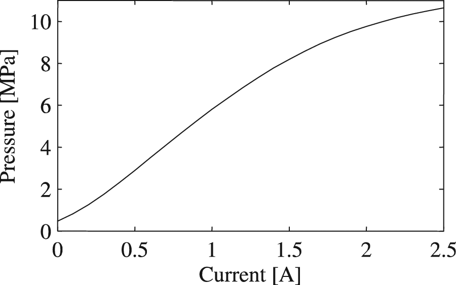
MR fluid characteristic curve.
MR test setup
To provide a constant pressure MR fluid supply, a conventional mobile hydraulic gear pump with aluminum housing was tested. Due to the abrasive nature of the MR fluid, the conventional gear pump was worn out within half an hour of operation. The wearing problem was solved by using KP DuroTec gear pump, manufactured by Kracht GmbH (Kracht Gmbh, Werdohl, Germany) that is specially designed for abrasive fluids. The pump has high-rigid spherical graphite iron housing and chemical vapor deposition (CVD)–coated gear runs that makes the pump tolerant of particles with a size <50 µm and hardness <2500 Vickers in the transfer medium (Kracht GmbH, 2008).
A picture of the developed MR constant pressure test setup is presented in Figure 2. The pump (11) is rotated by the servo motor (1) through the belt drive (5). The fluid reservoir (2) can be pressurized through the connection (3) to ensure a sufficient fluid supply to the pump, and inside the fluid reservoir, MR fluid can be cooled down by the heat exchanger and water circulation (4). The pressure relief valve (9) is used to limit the maximal output pressure of the test setup and arrows (8) and (10) are pointing out the fluid supply lines to the MR valve and back, respectively. The arrows (7) are pointing out the pump condition monitoring system that consists of two temperature sensors and one pressure sensor immediately after the pump. The tubes from the leakage channels of the pump are pointed out by arrows (6). The setup shown in Figure 2 has successfully been used as a fluid power supply during the identification of the MR valve and experiments described in this study. In order to give better understanding of the fluid flow and functionality of the MR test setup, a conceptual diagram of the hydraulic system is shown in Figure 3.
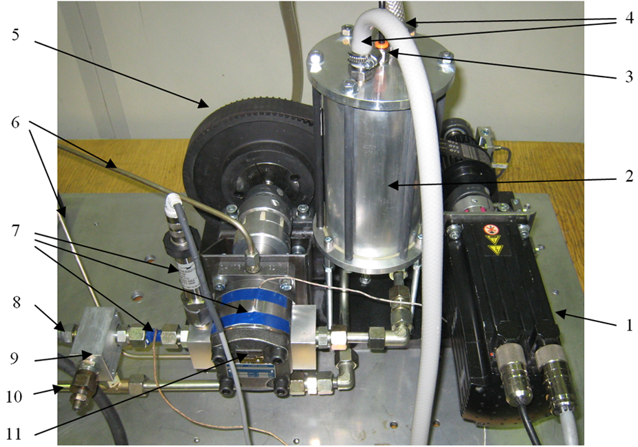
Picture of the MR test setup showing the functional components: (1) servo motor, (2) fluid reservoir, (3) tank pressurization connection, (4) heat exchanger connections, (5) belt gear, (6) leakage channels, (7) pump condition monitoring, (8) fluid supply line to the valve, (9) pressure relief valve, (10) fluid return line from the valve to the fluid reservoir, and (11) gear pump.
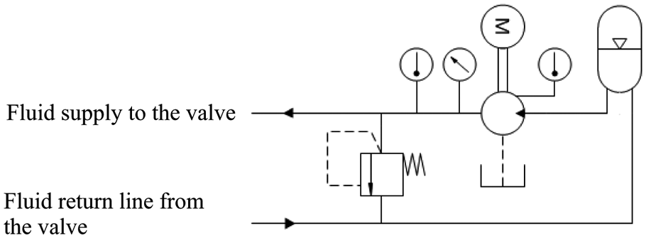
Conceptual diagram of the MR test setup.
Experimental valve
The prototype valve, designed for this study, is a square shaped one and has two separately controllable fluid gaps MR 1 and MR 2 where the fluid can be activated. Figure 4 illustrates the functional components of the valve that consists of two steel core parts, two coils, and MR fluid that flows through the valve. The core parts inside the valve are mounted into aluminum body, which is not depicted in Figure 4. The core parts are manufactured of Hiperco 50 steel, and in order to avoid eddy currents during fast magnetic field transients, laminated structure was used.
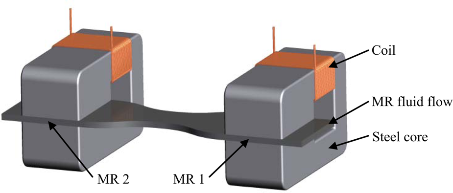
Schematic diagram that is equivalent to the functional structure of the MR valve.
In this design of the core parts, it is noteworthy that the shape of the fluid gap is rectangular and planar. In many studies, the shape of the fluid gap has been designed to be annular, which has been realized by using round core parts (Ai et al., 2006; Burton et al., 2004; Li et al., 2003; Nguyen et al., 2008). However, by using planar shape of the MR fluid gap, it is much easier to design an MR valve in which laminated steel can be used as a core material.
Figure 5 shows the MR valve with overlaid hydraulic diagram demonstrating the functional parts of the valve. Three pressure sensors P1, P2, and P3 are mounted to the valve to measure the pressure in the fluid supply line, actuator connection, and tank line, respectively. A small high-pressure accumulator, with precharge pressure of 3 MPa, is connected to the valve supply line to ensure sufficient fluid supply during pressure transients. The function of the low-pressure tank line accumulator, with precharge pressure of 0.2 MPa, is to prevent the pressure rise in the tank line when the fluid is bursted out of the valve.
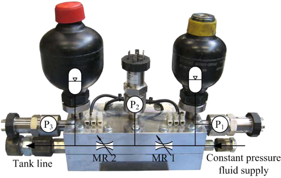
Experimental MR valve.
As a functional principle, the output pressure, P2, can be varied by controlling the currents of the electromagnets that activate the MR fluid in the fluid gaps MR 1 and MR 2. As the valve is mounted to an MR test setup with a constant pressure fluid supply, the maximum pressure in the actuator connection can be achieved when the fluid gap MR 2 is fully activated and the fluid gap MR 1 is deactivated. In practice, in this case, the fluid flow through the valve can be totally blocked since the maximum pressure of the MR test setup has been limited up to 10 MPa.
The magnetic circuit of the valve was designed in a way that the MR fluid can be nearly saturated by the electric current of 2 A. In the design phase, the geometry of the flow gap, the number of needed coil winding turns, and the relationship between the input current and the corresponding magnetic field intensity were estimated from the magnetic performance point of view by using Finite Element Method Magnetics (FEMM) software. In FEMM software, the MR fluid’s nonlinear property of permeability as a function of the intensity of the magnetic field can be taken into account, and the magnetic field strength in the fluid gap was able to be studied at different electric currents.
The meshed FEMM model of the MR fluid gap is presented in Figure 6. In the model, the magnetic properties of the core material were able to be selected from the material library of the software and 6000-series aluminum was used as a surrounding material for the core parts. The lead-in and lead-out sides of the MR fluid gap were bounded by semicircles in order to be able to use finer mesh inside the fluid gap and on the interface with the core material. Size of the triangular mesh inside the fluid gap was set to 0.05 mm (average height of the element), and in the core material, a size of 0.3 mm of the element was used.
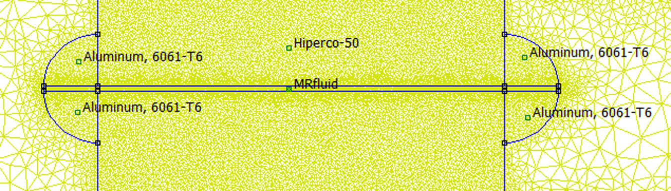
Meshed FEMM model of the MR fluid gap.
Figure 7 shows the solved magnetic flux density plot at electric current of 2.0 A. From Figure 7, it can be seen that the maximum of the flux density in the core material stays below 1.0 T if the regions next to the sharp corners are not taken into account. Based on this, it can be assumed that no saturation of the core material occurs with the current of 2.0 A. The red line in the MR fluid gap demonstrates the element that has been used for the integration of the magnetic field intensity in the fluid gap.
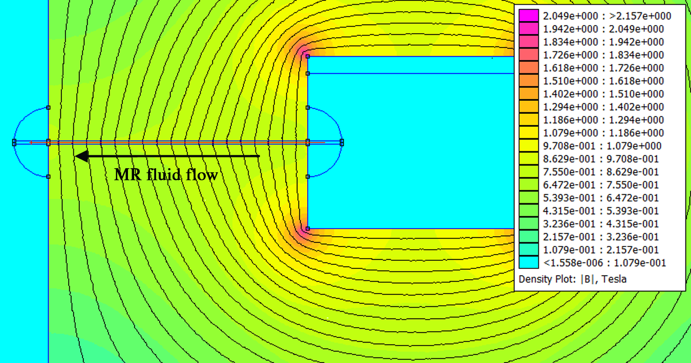
Magnetic flux density plot at electric current of 2.0 A.
Figure 8 shows the simulation results of the magnetic field strength in the MR fluid gap. The results have been analyzed from the red line depicted in Figure 7, and the dashed lines are pointing out the edges of the core material. The deviation of the magnetic field strength in the fluid flow direction can be seen to be very flat on each value of electric current, and the magnetic field strength responses linearly as a function of electric current, that is, if the electric current is doubled, the magnetic field strength will also be doubled. From Figure 8, the maximum value of the magnetic field strength at the electric current of 2.0 A can be analyzed to be approximately 164 kA/m.
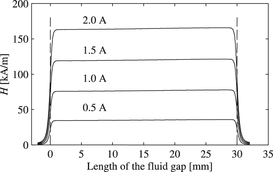
Simulated magnetic field strengths in the MR fluid gap.
The magnetic field–induced yield stress of the MR fluid is often represented as a Bingham plastic having both shear rate and viscosity-dependent yield strength and magnetic field–dependent yield strength. If the total stresses
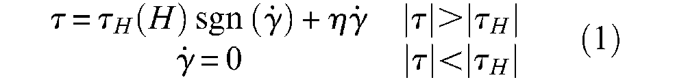
where
When the MR fluids are used in valve application and Bingham plastic model is adopted, the pressure difference over one fluid flow controlling fluid gap, that is, MR 1 or MR 2 in Figure 5, can be approximated with the following equation (Jolly et al., 1998)
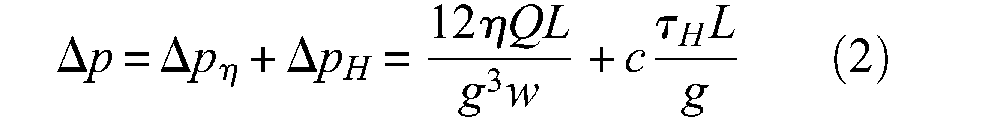
where
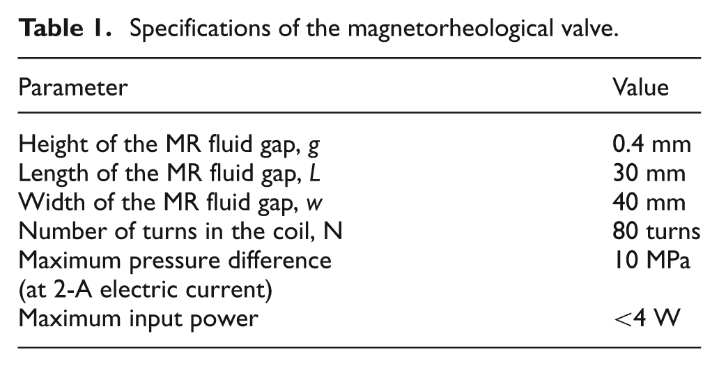
In the design process of the prototype MR valve, the fluid gap defining parameters g, w, and L were iterated in relation to the magnetic properties of the valve. As design criteria, the static hydraulic performance of the valve was defined to be able to generate pressure difference of approximately 10 MPa in the actuator connection, that is, the pressure difference between the pressure sensors P2 and P3, when the fluid gap MR 2 is activated with the electric current of 2 A. By combining the FEMM simulation results of the magnetic circuit with the characteristic curve of the MR fluid (Figure 1) and the equation (2), the output pressure P2 can be estimated as a function of the electric current. The simulated characteristic curve of the developed MR valve is presented in Figure 9. In the simulation the viscosity of the MR fluid was 0.09 Pa-s and the average volume flow through the valve was estimated to be 40 cm3/s. The final design parameters of the prototype MR valve are listed in Table 1.
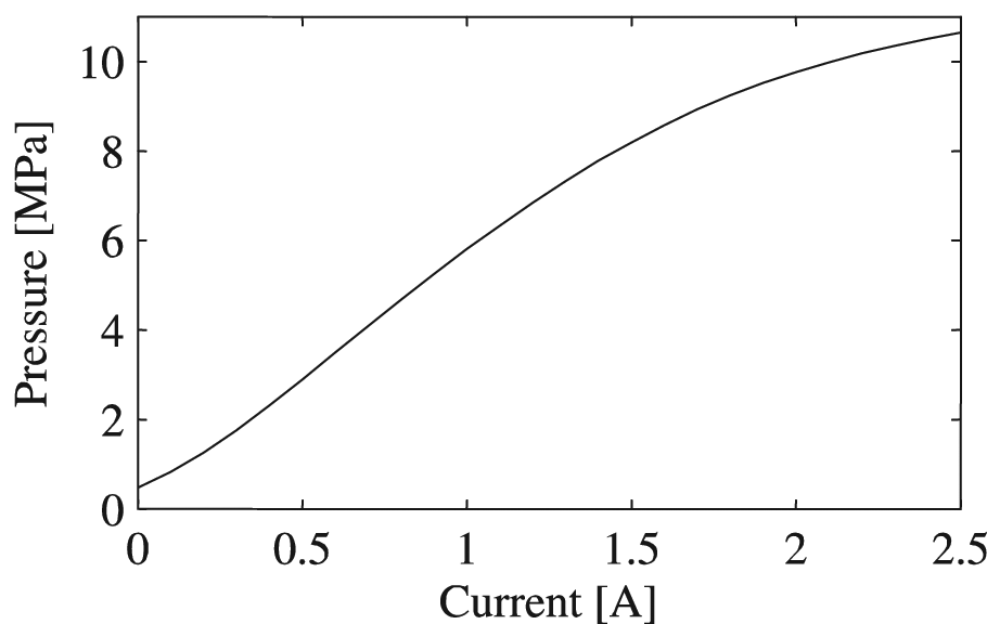
Characteristic curve of the MR valve.
Specifications of the magnetorheological valve.
Results and discussion
Model identification
In this study, the model identification of the MR system was carried out by data-based black box modeling. In this method, the model is identified based on the input and output signals of the system that are measured in open-loop control configuration (Ljung, 1999). This configuration is illustrated in Figure 10, where u(t) is the control signal, i(t) is the electric current, p(t) is the output pressure, and y(t) is the output signal. The MR system in this case consists of the valve, current sources, dynamics of the pressure transducers, and MR fluid. It is also considerable that the valve itself combines models of the strength of the structure, the magnetic circuit, and the hydrodynamics inside the valve. The input of the system is an analog control signal varying from −0.4 to 0.4 V, and the output signal is the pressure P2 in the actuator connection.
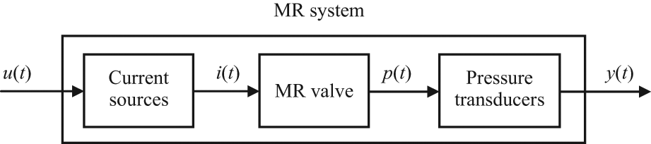
Open-loop configuration.
The data for the MR system identification were measured by using sine excitation. In these measurements, the valve was excited at each frequency for 1 s after which the certain frequency, amplitude difference, and the phase difference between the reference and the output pressure P2 were recorded. The bandwidth of the excitation signal was selected to limit between 25 and 2000 Hz, and it was divided evenly in 100 frequency steps. Frequencies below 25 Hz were estimated to belong to the static operating range of the valve, and frequencies over 2000 Hz were assumed to be beyond the dynamics of the MR valve. The static pressure level used in the identification was set to 4 MPa, corresponding to approximately half of the maximum operating pressure of the valve. The peak-to-peak value of agitation pressure for identification was chosen to be 4 MPa. Thus, the sinusoidal pressure reference varied between 2 and 6 MPa during the identification.
By using the acquired frequency response data, MATLAB System Identification Tool was used to identify the model for the MR system, and after iterative model evaluations, a sixth-order state space model was chosen to estimate the response of the MR system. In general, the state presentation of a system can be formulated as

where
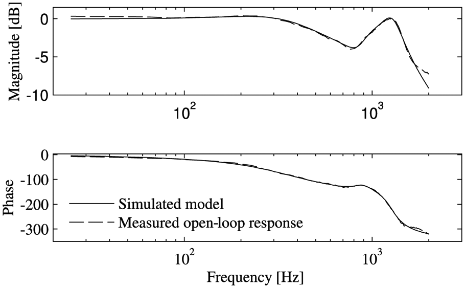
Measured open-loop and simulated model response of the MR system.
Controller
The identified model of the MR system was imported to MATLAB Control System Toolbox in order to simulate and tune the response of the controlled system. The block diagram of the closed-loop MR system is presented in Figure 12, where r(t) is the pressure reference signal and e(t) is the pressure error signal.
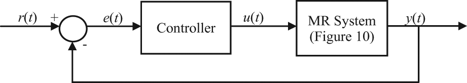
Control architecture of the MR system.
The controller was based on the proportional–integral–derivative (PID) structure, and the transfer function Gcontroller(s) of the tuned controller can be written as follows
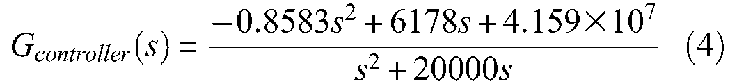
The controller was tuned by using an internal model control (IMC)–based tuning algorithm. The IMC algorithm provides an easy framework for tuning a controller with only a single adjustable parameter that is related to the speed of the response of the system. In this study, the performance of the closed-loop system was estimated by simulating the step response of the system and as tuning criteria, the response time and the overshoot of the output signal was used (Rivera et al., 1986).
To realize the control system, National Instruments LabVIEW environment was used and the tuned controller was imported to the control software in order to measure the pressure response of the closed-loop MR system. In the real-time control, the control frequency of 10 kHz was used.
Closed-loop measurements
Frequency response
The pressure frequency response of the closed-loop MR system was measured by using the same measurement procedure as used in the model identification depicted in section “Model identification.” The amplitude of the sine excitation was increased so that the full performance of the controlled MR system was able to be studied. The measured results of the open-loop and the closed-loop responses are presented in Figure 13(a) and (b), and the −3-dB level of the magnitude response and the −90° level of the phase graph are pointed out with the dashed lines. In the magnitude graph of the open-loop system (Figure 13(a)), the 0-dB level corresponds to a pressure level of 3.5 MPa, whereas in the closed-loop system (Figure 13(b)), the 0-dB level corresponds to 8.0 MPa.
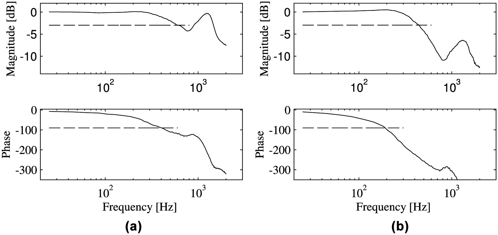
(a) Frequency response of the open-loop system. (b) Frequency response of the closed-loop system.
The first examination of the results proves that the open-loop system has a very flat frequency response before the magnitude response starts to descent. This indicates that there exist no disturbing mechanical resonances in the valve construction and that the MR system is well suited for the control applications. Natural frequency that appears at the frequency of over 1 kHz is assumed to be dominated by the characteristics of the hydraulic circuit of the valve.
By analyzing the closed-loop system results, it can be found out that the controlled MR system also has very flat magnitude response up to 300 Hz at the pressure level of 8.0 MPa and the −3-dB level of the magnitude response can be found at the frequency of 445 Hz. From the phase diagram, it can be seen that the controlled system crosses −90° level at the frequency of 194 Hz, whereas the open-loop system reaches the same level at the frequency of 404 Hz. This indicates that the closed-loop system is slower compared to the open-loop system, but on the other hand, this can be understood by taking into consideration the interaction chain in the open-loop and closed-loop MR systems.
In the open-loop system, depicted in Figure 10, the reference signal is fed directly to the current sources that generate the magnetic field–inducing electric currents. The current sources are carefully fine-tuned, meaning that the response times of the electric currents cannot be made faster by boosting the reference signal. Inside the valve, the laminated core material has been found to enable fast magnetic field transients resulting in negligible delay between the electric current and the intensity of the magnetic field. Also the dynamics of the yield stress of the MR fluids has been reported to be beyond the frequency bandwidth of the MR valve in which case the response of the MR fluid cannot be made faster by using higher intensities of the magnetic field (Goncalves et al., 2006). As an outcome of this reasoning, it is suggested to be characteristic for the MR system used in this study that the pressure response of the valve cannot be made faster by boosting the reference signal by a controller in a closed-loop system. However, by closing the pressure feedback loop, the effect of the mechanical resonance at higher frequencies to output pressure can be diminished and the accuracy of the pressure response can be improved, which is discussed more in detail in the following section.
Quasi-static response
The static responses of the open-loop and pressure-controlled MR system were measured by using a 1-Hz sine excitation. The pressure offset at the 0-V control signal was chosen to be approximately 4.9 MPa, and the amplitude of the reference signal was chosen in a way that the valve generates the pressure difference of ±3 MPa. The static responses of the MR system in open loop and closed loop are compared in time domain in Figure 14(a) and (b).
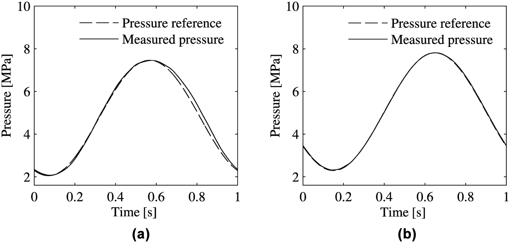
(a) Static response of the open-loop system. (b) Static response of the closed-loop system in time domain.
From the open-loop static results in Figure 14(a), it is interesting to notice how accurately the pressure signal follows the given reference and only little difference between two signals can be found. In Figure 14(b), the influence of the pressure controller can be noticed as no detectable difference between reference and measured pressure signals. If the measured pressure is plotted as a function of the reference signal over one cycle, the static characteristic properties of the MR system can be studied in a more illustrative way, which is presented in Figure 15(a) and (b).
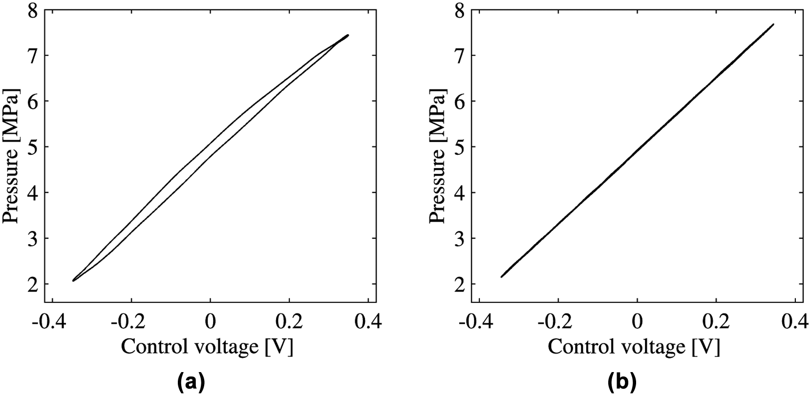
(a) Static response of the open-loop system. (b) Static response of the closed-loop systems.
From Figure 15(a), it can be noticed that the open-loop pressure response of the system is fairly linear with only small hysteresis. The hysteresis in the pressure signal is assumed to be caused by the remnant magnetism of the core parts of the valve. However, a system with this small hysteresis could already be used in some applications without closed-loop pressure feedback information.
In the case of controlled results in Figure 15(b), it can be found that the pressure response of the MR system is very linear with no hysteresis. The effect of the integrating factor in the controller can be noticed as disappearance of the slight nonlinearity in the open-loop response and as the improvement of the accuracy of the output pressure in proportion to the control signal. It is also essential that by closing the pressure feedback loop, the output pressure of the system becomes more robust against changes in process, that is, in the fluid itself. These changes may be caused, for instance, by contamination of the fluid, temperature variations, or change of the air ratio in the fluid. This is in contrast to the open-loop system, where these kinds of changes in the fluid properties may cause large changes to the output pressure.
Conclusion
In this study, a novel MR valve has been developed that is designed to be able to operate at high frequencies. The pressure control properties of an MR valve have been studied by closing the pressure feedback loop.
The open-loop frequency response of the output pressure of the MR system was measured by using sinusoidal excitation, and a sixth-order state space model was identified for the system based on the frequency data. Further on, the identified model was used for tuning a controller for the closed-loop MR system. As a controller, a PID controller was chosen and finally the tuned controller was implemented to a real-time control computer.
The frequency response measurements of the closed-loop MR system proved that with MR technology, the fluid flow and pressure can be controlled up to several hundred hertz with the pressure difference of 8.0 MPa. The dynamic performance of the MR system was documented to reach the −3-dB level at the frequency of 445 Hz. The static measurements of the closed-loop system demonstrated how the hysteresis in the pressure response can be removed and a very linear response can be reached by using a controller with an integrating factor. It is also notable that by adding a controller into the MR system, the total robustness of the system against changes in the process, that is, contamination of the fluid, temperature variations, and changes of the air ratio in the fluid, can be improved.
By the frequency response and the static results of the closed-loop MR system, it has been demonstrated that the MR technology has a strong potential for fast servo applications with good accuracy. In future works, the MR technology will be applied to the field of high-frequency pressure and force control, active vibration control in smart structures, fast semiactive dampers, and active shock control.
Footnotes
Funding
This research was funded by Academy of Finland.