
Abstract
A novel approach is employed for the prediction of stress, electrical, and magnetic fields generated by applying combined loadings on damaged composites that consist of periodic electromagnetothermoelastic layers. The damage may represent cavities and cracks and must be localized in the sense that its effect on the remote-loaded boundaries of the composite is negligible. This approach is based on the combined use of the representative cell method, the higher-order theory, and the high-fidelity generalized method of cells micromechanical model. In the framework of the representative cell method, the problem for a periodic composite that is discretized into numerous identical cells is reduced to a problem of a single cell in the discrete Fourier transform domain. In the framework of the higher-order theory, the resulting governing equations and interfacial conditions in the transform domain are solved by dividing the single cell into subcells and imposing the latter in an average (integral) sense. The high-fidelity generalized method of cells is utilized for the prediction of the proper far-field boundary conditions, which are based on the unperturbed effective properties of the composite. The inverse of the Fourier transform provides the real elastic field at any point of composite with localized effects. The damage existence is modeled by introducing fictitious unknown eigenfields that are computed by an iterative procedure. This modeling is verified by a comparison with five analytical solutions of cavities and cracks embedded in piezoelectric and electromagnetoelastic materials. Several applications of cracked layered composites are given.
Keywords
Introduction
Electromagnetoelastic composites form an important class of smart materials. This is due to the existing coupling between the electric, magnetic, thermal, and mechanical effects that can be utilized for sensing, actuation, and detection. Furthermore, an additional electromagnetic coupling in these composite exists that is absent in the monolithic electromagnetoelastic phases that can be also utilized for sensing. Electromagnetoelastic materials can be also employed in multilayer structures and laminated composites for sensing and actuation. Thus, Sosa and Pourki (1993), for example, presented a method for the analysis of electromechanical behavior of multilayer structures where the main components are piezoelectric materials. Gopinathan et al. (2000), on the other hand, published an extensive discussion and review of theories for piezoelectric laminates where classical and shear deformation theories are discussed, in conjunction with sensor and actuator problems.
It is obviously important to predict the effective properties of these composites. To this end, several micromechanical models have been employed, for example, Carman et al. (1995) (who employed the concentric cylinder model); Li and Dunn (1998), Wu and Huang (2000), and Li (2000) (who employed the Mori–Tanaka method); and Aboudi (2001) (who employed a homogenization technique for periodic composites).
The piezoelectric and piezomagnetic phases of the electromagnetoelastic composites are usually brittle (e.g. lead zirconate titanate (PZT) is a piezoelectric material, which is very stiff and brittle). Hence, fracture may take place in these composites during fabrication or service. Several types of flaws in multilayer actuators have been described by Winzer et al. (1989). The introduction of cracks in composites to be analyzed by standard micromechanical models like the Mori–Tanaka method is not possible (since these methods are based on the average stresses in the phases). Similarly, the introduction of cracks in composites with periodic microstructure is not possible because the crack would be incorporated into the analysis in a periodic manner, which is not a realistic situation. When a single crack or several cracks occur in a periodic composite, the periodicity assumption is lost because it is not possible to identify a repeating unit cell that represents the multiphase composite that can be analyzed. Therefore, these micromechanical models are not applicable anymore.
In a recent investigation, Aboudi and Ryvkin (2012) presented an analysis for a distributed damage over a confined region within fiber-reinforced composites. It is based on the combination of the representative cell method (Ryvkin and Nuller, 1997), the high-fidelity generalized method of cells (HFGMC) micromechanical model (Aboudi, 2004), and the higher-order theory (Aboudi et al., 1999). In the first approach, the discrete Fourier transform is applied on the periodic composite in which the distributed damage effects have been included. As a result, a representative cell problem is obtained in the transform domain. The formulation of the specific boundary conditions that should be imposed in this problem requires the knowledge of the effective elastic moduli of the undamaged periodic composite. These elastic effective moduli are established by the HFGMC micromechanic analysis that forms the second approach. The solution of the governing equations in the transform domain is achieved by employing the higher-order theory that was originally developed for the analysis of functionally graded material. In the framework of this theory, the representative cell is divided into several subcells in which a second-order expansion of the displacements in the transform domain is employed and the governing equations and the interfacial and boundary conditions in this domain are imposed in the average (integral) sense. Once the solution of the representative cell problem has been established for all Fourier harmonics, an inverse transform is employed to obtain the actual elastic field in the composite. The effect of the localized damage appears in the constitutive equations in the form of eigenstresses. These field variables are not known in advance, and therefore, an iterative procedure was employed that establishes the requested elastic field in the composite to a preassigned degree of accuracy.
The above-mentioned approach is presently applied to investigate the mechanics and electric and magnetic field distributions caused by a single or a system of cracks in periodically layered electromagnetothermoelastic composites that are subjected to combined loadings. In addition, the analysis of Aboudi and Ryvkin (2012) is presently generalized for the modeling of inclusions embedded in this type of composites. It is shown that this approach is capable of analyzing stiff as well as soft inclusions with respect to the surrounding matrix (including cavities).
The proposed approach is verified by comparisons with five cases in which analytical solutions are available. These include inclusions and cracks in piezoelectric and electromagnetoelastic materials under combined loadings.
The present article is organized as follows. In sections “Governing equations” and “Method of solution,” the governing equations and the methods of solution are presented. The “Verifications” section presents the five verifications, which is followed by the “Application” section. Finally, the “Conclusion” section concludes the article.
Governing equations
Consider electromagnetoelastic linear materials in which the axis of symmetry is oriented in the x3-direction. Piezoelectric materials are obtained as a special case in which the magnetic effects are ignored. These materials are governed by the following constitutive equations
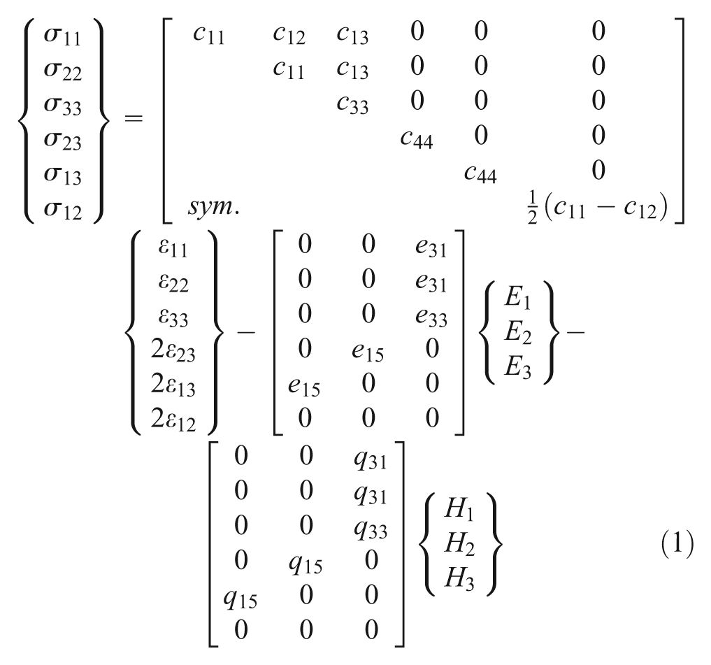
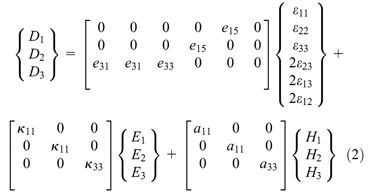
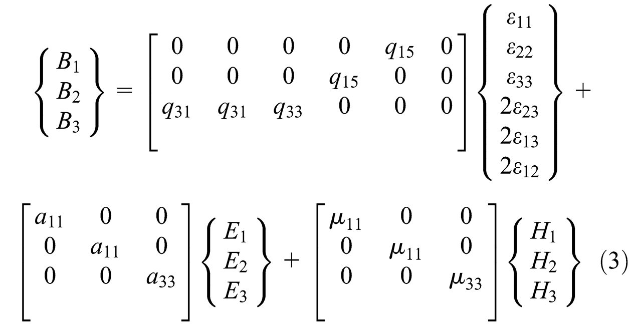
In these equations,
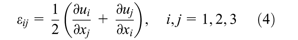
The components of the small strain tensor
The components of the electric field

Similarly, the components of the magnetic field

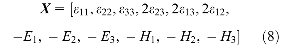
The earlier constitutive equations are applicable in the isothermal case. In order to incorporate the thermal effects, let us define the following vector

where

Consequently, equations (1) to (3) can be written in the presence of thermal effects described by a temperature deviation

where the square 12th-order symmetric matrix of coefficients
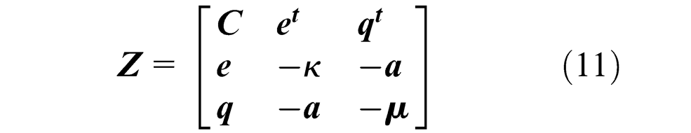
and

In equation (11),
In order to include damage effects in the considered electromagnetoelastic material, damage variables
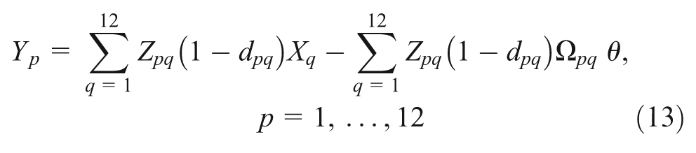
As in Aboudi and Ryvkin (2012), let us write this equation in the form

where of

It will be shown in the following that for a monolithic electromagnetoelastic material, 15 different damage variables will enable the modeling of cracks and the analysis of stiff and soft inclusions (including cavities) with respect to the material within which they are embedded. For elastic isotropic materials, just two independent damage variables would be needed (cf. Ju, 1990).
In the present investigation, we consider a periodically layered composite in which one of its electromagnetoelastic layers is damaged by the appearance of a transverse crack perpendicular to the layering direction together with two symmetric interfacial cracks, thus forming an H-crack. The transverse crack is assumed to exist in the weak layer (denoted by m) whose width is
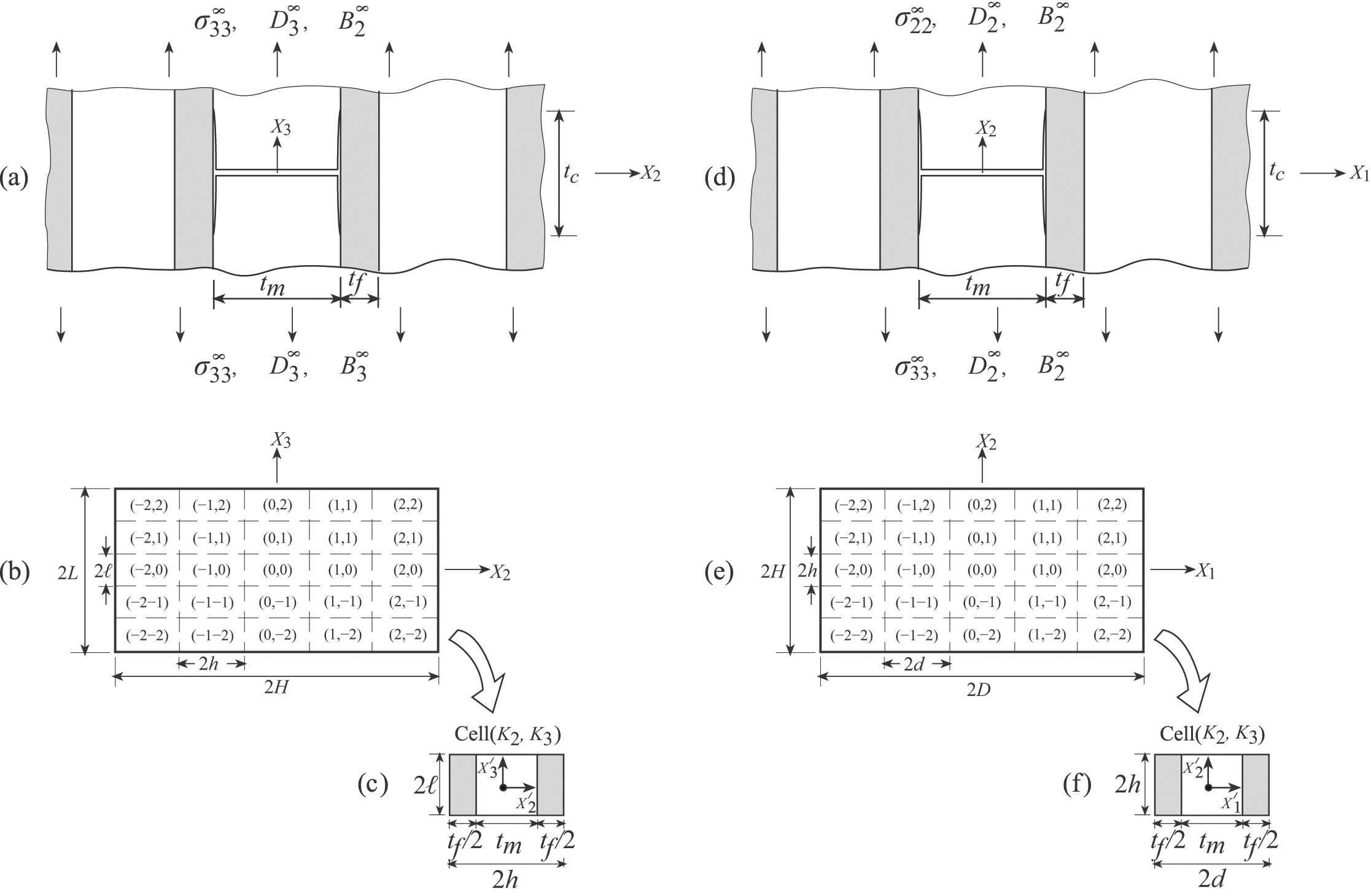
(a) A periodically layered composite with transverse and interfacial cracks (thus forming an H-crack) whose leading edges are perpendicular to the poling direction
The response of the considered damaged layered composite can be determined by satisfying the static equilibrium equation that, in the absence of body forces, is given by

Furthermore, in the absence of volume charges, the following Maxwell’s equation

must be satisfied, and similarly

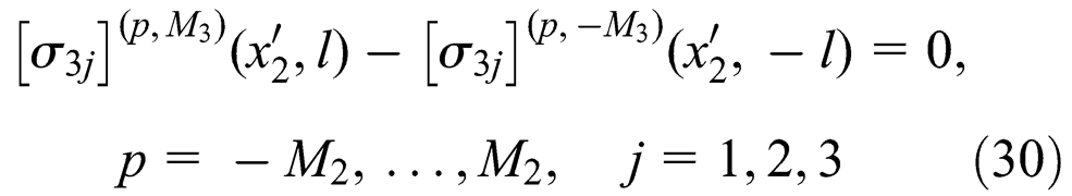
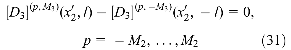
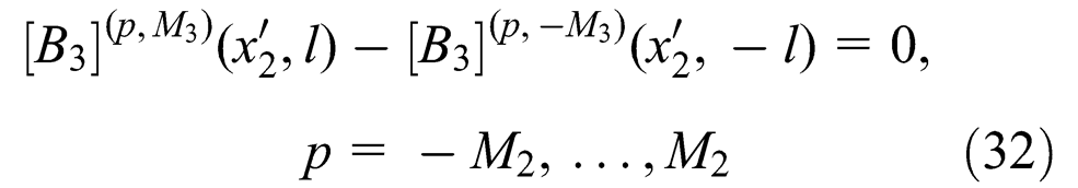
In addition, the interfacial conditions that require the continuity of displacements
Method of solution
Far away from the damaged layers, the periodically bi-layered electromagnetoelastic composite behavior is governed by its effective moduli that can be determined by an appropriate micromechanical analysis (e.g. Aboudi, 2001). In the following, we derive the method of solution for the configuration shown in Figure 1(a) since a similar formulation is applicable to the one shown by Figure 1(d).
To this end, let us consider a rectangular domain
The governing equations (16) to (18) of the materials within the cell


The constitutive equation in the cell, equation (14), can be written as

where the components of
In order to formulate the continuity conditions that the various variables should fulfill, let us define the vectors
These vectors assemble the components of the displacements, tractions, electric displacements, magnetic flux densities as well as the electric and magnetic potentials on a plane perpendicular to the x
r
-axis at the cell
The continuity of displacements, tractions, electric potential, electric displacements, magnetic potential, and magnetic flux densities between adjacent cells should be imposed. Thus

where

where
In the following, the appropriate form of the far-field boundary conditions that specify the electromagnetoelastic field at the opposite sides

as well as
The displacements, electric potential, and magnetic potential at the opposite sides, on the other hand, differ by certain jumps as follows
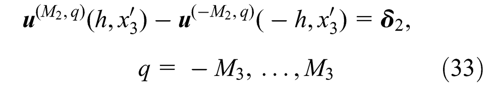
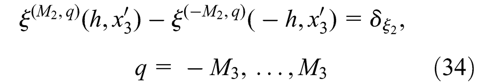
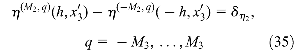
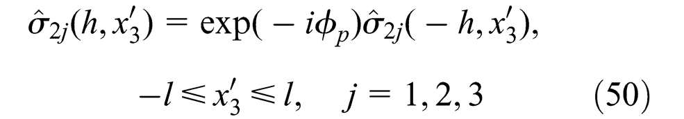
and
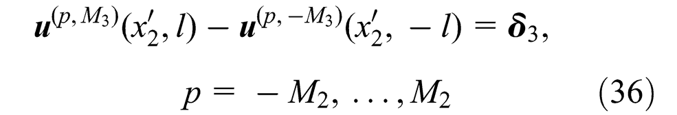
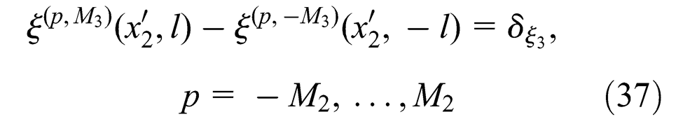
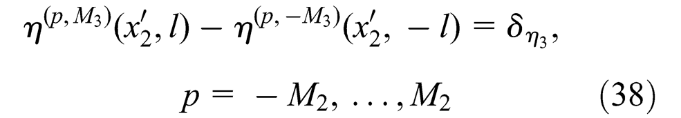
where

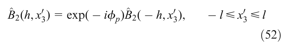
and

and

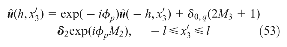
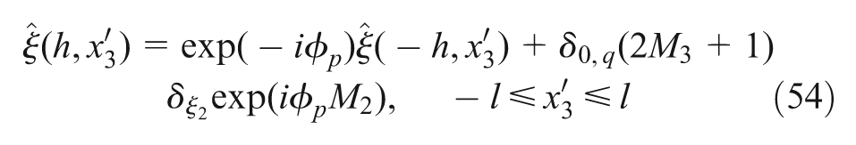
where
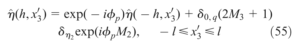
The far-field values

with

where
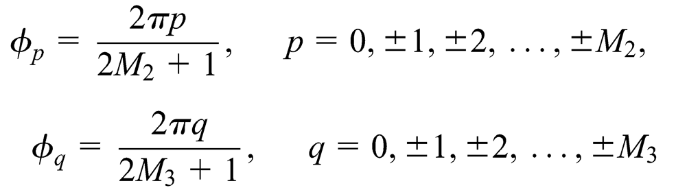
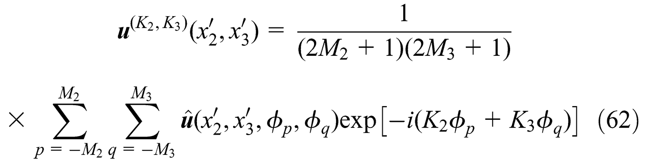
The double discrete Fourier of the displacement vector
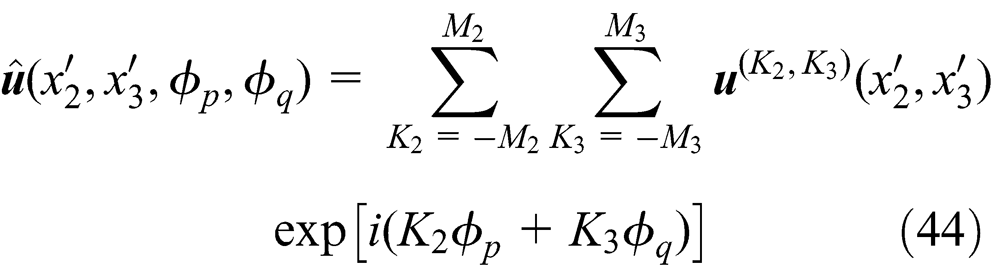
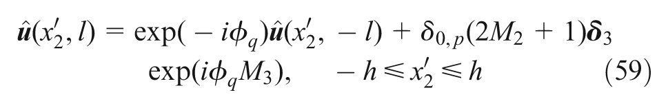
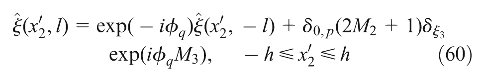
where
The application of this transform to the boundary problem (19) to (38) for the rectangular domain


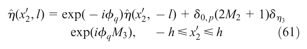
and

where the components of the transformed eigenfield vector are given by
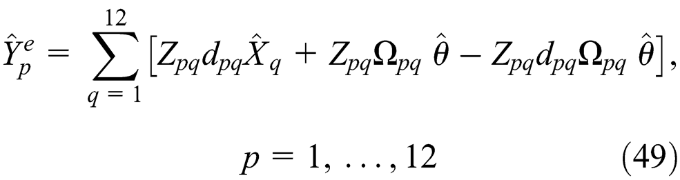
The conditions relating the opposite boundaries of the representative cell in the perfectly elastic problem were derived by Aboudi and Ryvkin (2012). By generalizing their approach, one obtains from equations (25) to (38) that

and
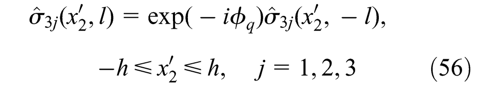
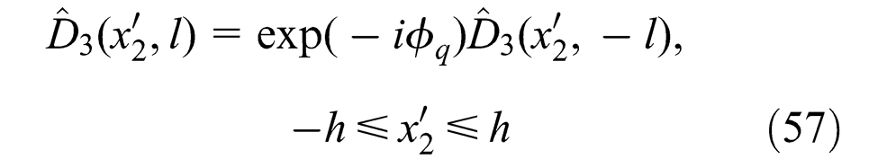
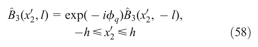
where
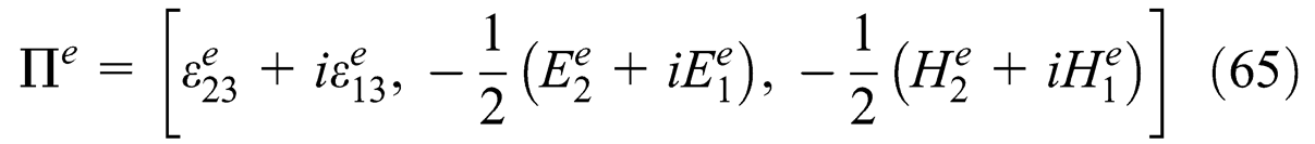
In these equations,
The representative cell boundary value problem (45) to (61) (together with the standard continuity conditions at the interfaces between the phases) is solved by employing the higher-order theory (Aboudi et al., 1999) to which the electromagnetic equations and constitutive relations should be incorporated. According to this theory, the domain
Once the solution in the transform domain has been established, the actual electromagnetoelastic fields can be readily determined at any point in the desired cell
In the application of this theory, the eigenfield vector
Start by assuming that
Apply the inverse transform formula to compute the stress field. The latter can be employed to compute the current eigenfield
Compute the transform of
Solve again the equations in the transform domain.
This procedure should be continued until a convergence to a desired degree of accuracy is achieved.
The computational efficiency of the present approach can be illustrated by considering the case with H-cracks. In order to ensure that the applied remote loading is sufficiently far away from the crack, the region has been divided into
Verifications
There are several solutions that provide analytical expressions that can be employed to verify the accuracy of the results obtained by the present approach. These verifications are illustrated in the following five examples.
It should be noted that in both the “Verifications” and “Application” sections, the order of magnitudes of the values of the applied far-field are about
Circular inclusion in piezoelectric material under antiplane mechanical loading
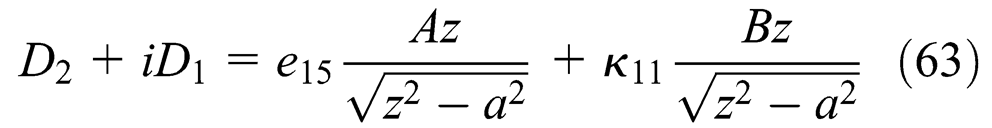
For a circular piezoelectric inclusion embedded in an infinite piezoelectric medium that is subjected to remote antiplane mechanical loading and in-plane electric one, closed-form solution of the electro-elastic field is available (Pak, 1992). The axis of the inclusion is parallel to the poling direction, that is, it is oriented in the x3-direction, and the configuration shown by Figure 1(d) to (f) is applicable. The closed-form solution, formulated in polar coordinates
To this end, consider
Elastic properties.
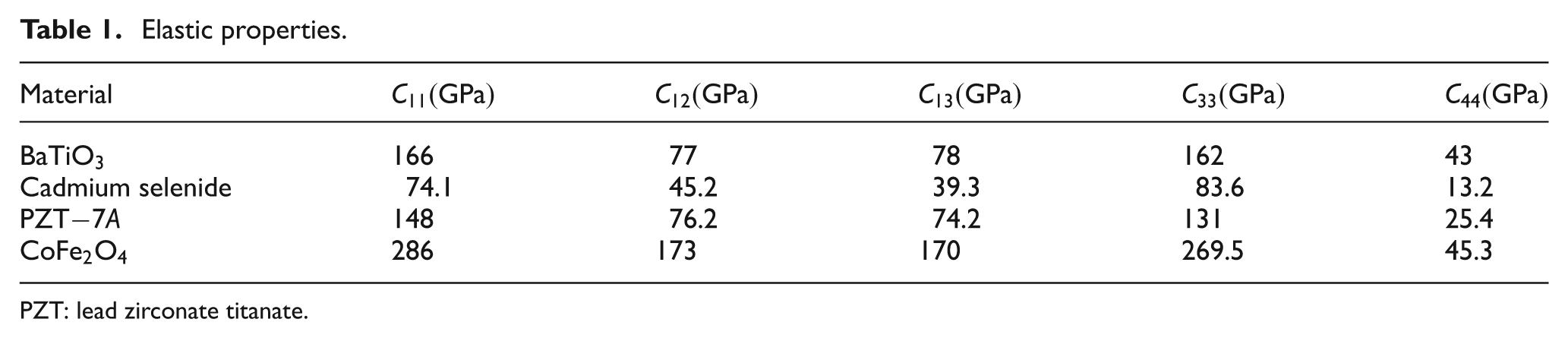
PZT: lead zirconate titanate.
Electric properties.
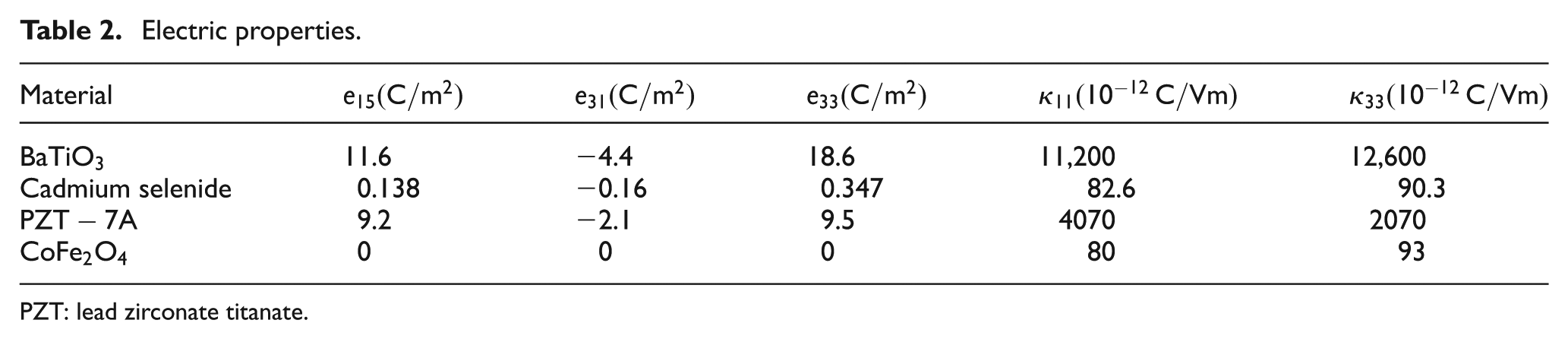
PZT: lead zirconate titanate.
A stiff inclusion (
A soft inclusion (cadmium selenide) embedded in the stiff matrix (
A cavity within the stiff matrix (
In all these three cases, the far-field loading is given by
Figure 2 exhibits comparisons between the resulting stresses and electrical displacements obtained from the closed-form solution and the present approach. It can be noted that very good agreements exist. The particular low order of magnitude of the scale of Figure 2(b) shows a slight difference between the two solutions within the inclusion. It is obvious that more cases could be considered (e.g. a cavity in the soft cadmium selenide matrix) and verified by a comparison with the closed-form solution.
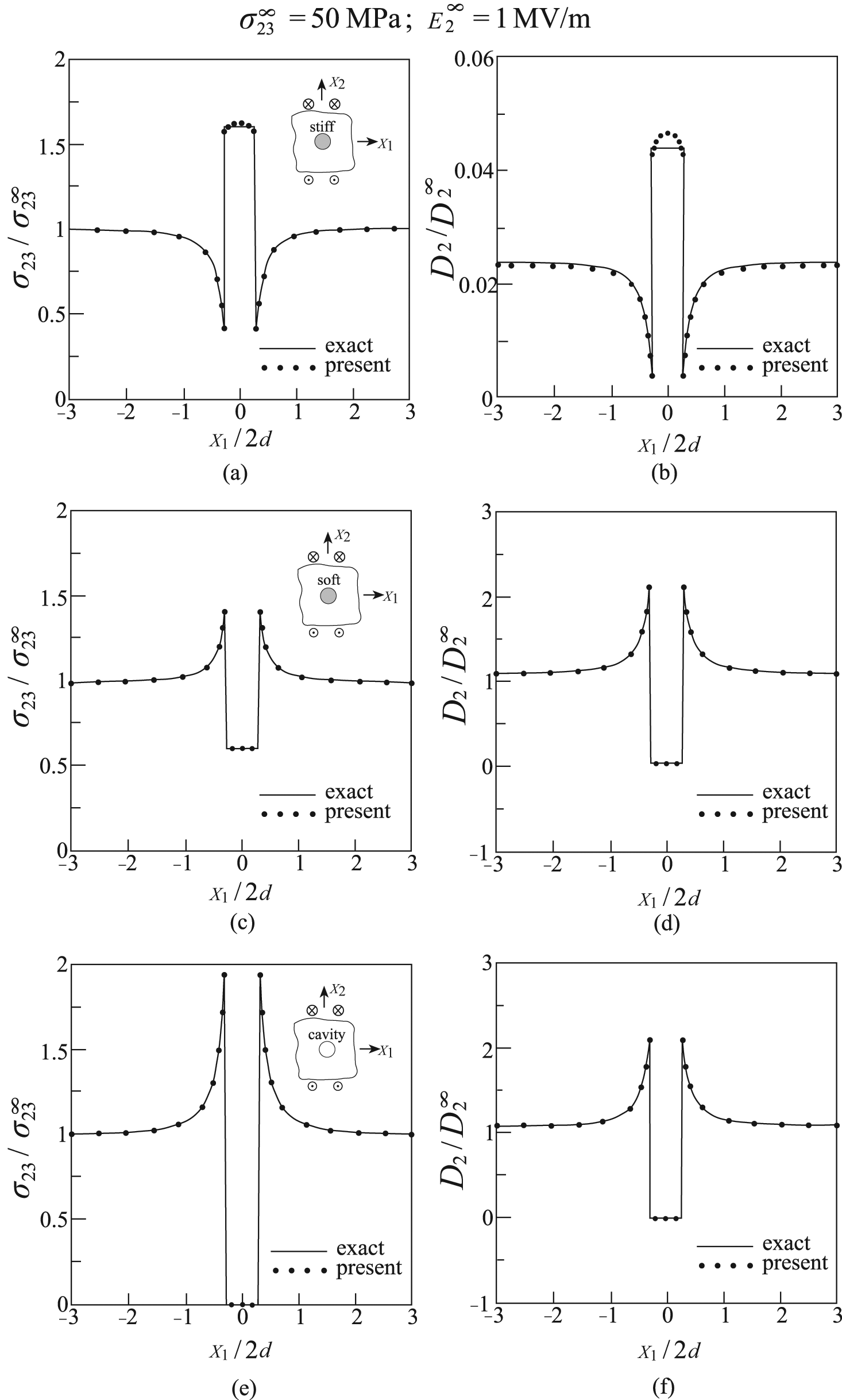
Comparisons between the exact solution and present approach for the variation along
Crack in piezoelectric material under antiplane mechanical loading
A closed-form solution for a crack of length

where
In our present approach, the crack region is modeled by vanishing damage variables
A comparison between the exact solution and present approach for the variation of the stress and electrical displacement along the crack’s line
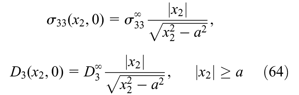
Circular cavity in piezoelectric material under in-plane loadings
Exact solution for a elliptical cavity embedded in a piezoelectric material that is subjected to remote in-plane mechanical loading has been presented by Sosa (1991). Here, the axis of the cavity is perpendicular to the poling direction
A comparison between the exact and present solution for the variation of the (a) stress and (b) electrical displacement along
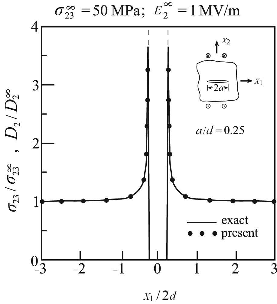
Crack in piezoelectric material under in-plane loadings
The closed-form solution of Sosa (1991) for elliptical cavity provides, as a special case, the mechanical and electrical fields in a piezoelectric medium with an embedded crack. Here, the leading edge of the crack is perpendicular to the poling direction
The veracity of the present method of solution can be verified by considering two cases in which the remote loading is parallel and perpendicular to the poling direction of a piezoelectric material (PZT-7A). In the first case, the crack extends along
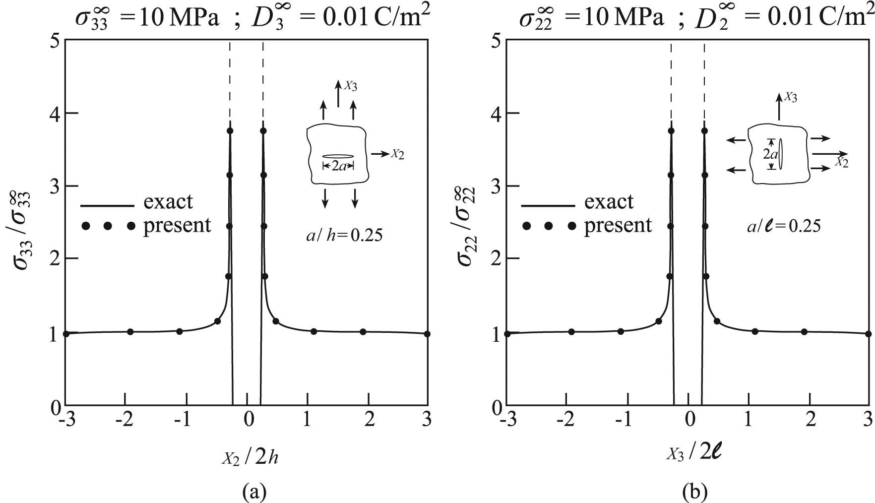
Comparisons between the exact and present solution for the variation of the stress and electrical displacement in a cracked PZT-7A material along the crack’s lines. (a) The remote in-plane loading is given by
In the aforementioned solutions, the surfaces of the cavity and crack were assumed to be electrically impermeable, namely, the normal electric displacement component is zero. Permeable solution for an elliptical cavity in a piezoelectric material has been presented by Sosa and Khutoryansky (1996). Comparisons of the present approach with this latter exact solution also revealed excellent agreements. However, the solutions of Sosa (1991) and Sosa and Khutoryansky (1996) for impermeable and permeable crack boundary conditions are very close as long as the stress and electric field variations are investigated.
Square inclusion in electromagnetoelastic material under antiplane mechanical loadings
Thus far, the predicted results from the present approach have been verified in the case of piezoelectric materials under various types of loading. It is possible to employ the analytical solution that has been presented by Wang and Shen (2003) for a rectangular inclusion whose sides are parallel to the directions
The method of solution is based on Ru’s method (Ru, 1999), which employs analytical continuation and conformal mapping. The resulting analytical solution is valid within the rectangular inclusion. It is in fact an approximate solution since it is based on a conformal mapping to a unit circle of the rectangular inclusion that includes infinite number of terms, the truncation of which results in an approximate solution (see Ru, 1999).
Since the electromagneto-coupling term is included in the considered analytical solution, the present verification has been carried out by considering a unidirectional fiber-reinforced piezoelectric/piezomagnetic
Magnetic properties.
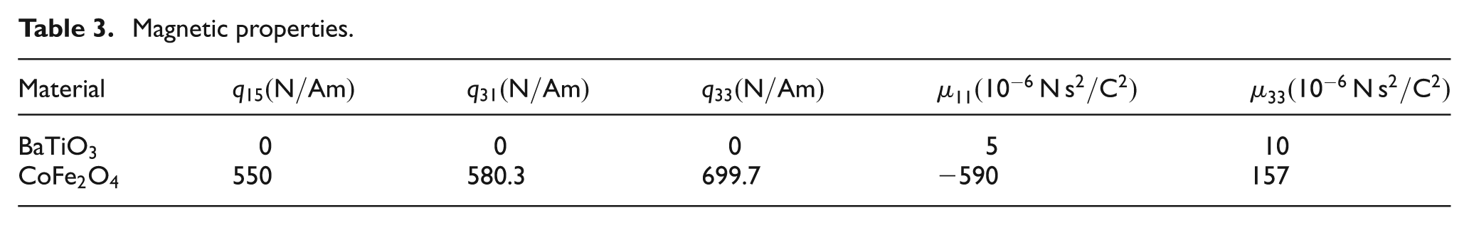
Figure 6(a) to (c) shows a comparison between the approximate analytical solution and the present approach for the stresses within the square inclusion. Satisfactory agreements and tendencies can be observed. These stresses, as predicted by the present solution, are shown in Figure 6(c) and (d) within and outside the inclusion along x1-axis. Finally, Figure 7(a) to (d) shows the corresponding variations of the electrical displacements and magnetic inductions as predicted by the present approach.
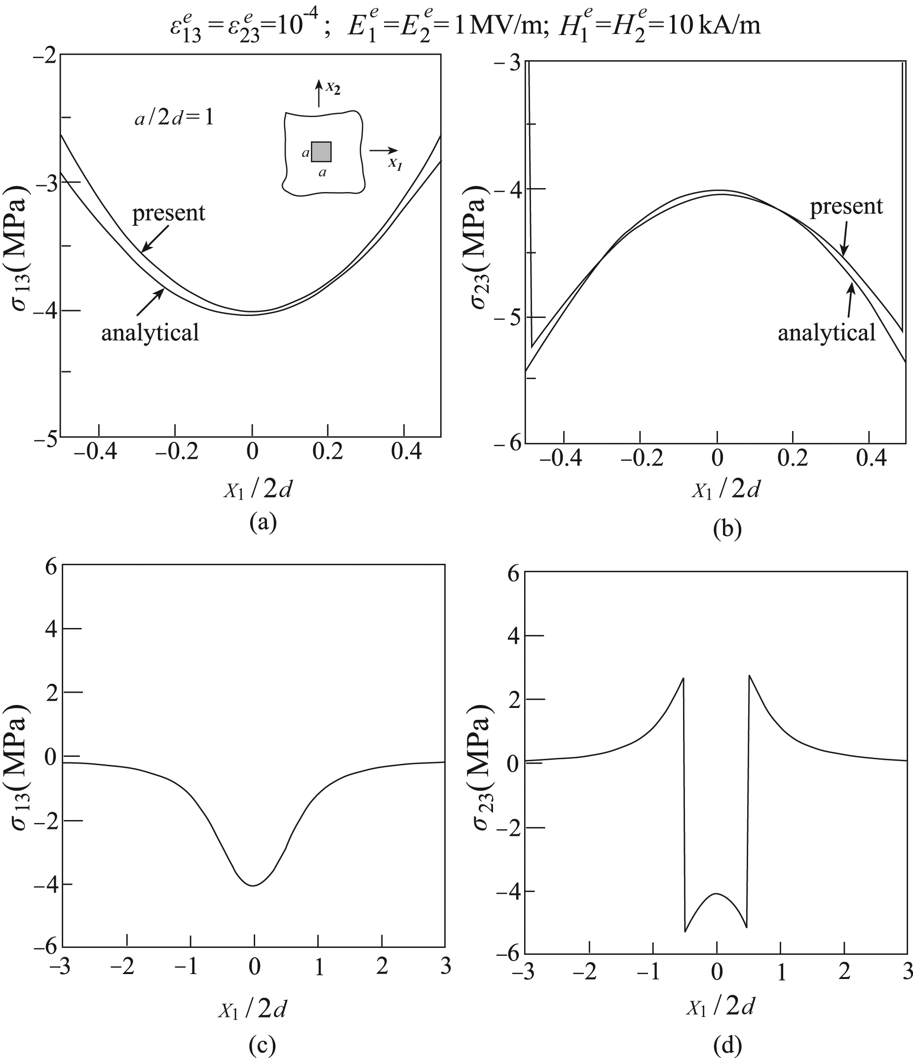
A square inclusion embedded within an infinite unidirectional electromagnetoelastic
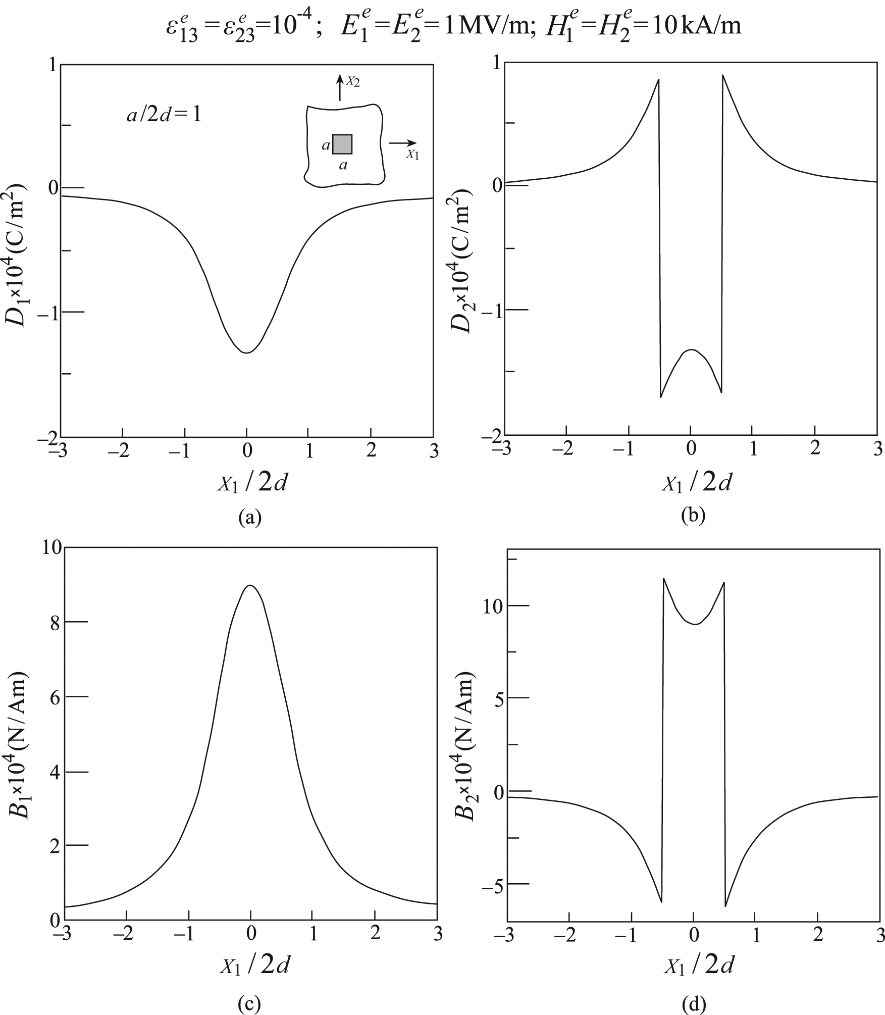
A square inclusion embedded within an infinite unidirectional electromagnetoelastic
Applications
In the previous section, results have been presented under circumstances where analytical solutions to be compared and verified with are available. In the present section, three applications of the proposed approach are given under more complicated circumstances. These include a cavity embedded in electromagnetoelastic medium, a layered piezoelectric composite with a transverse and H-crack, a layered electromagnetoelastic composite with an H-crack, and a layered piezoelectric composite with an H-crack under elevated temperature.
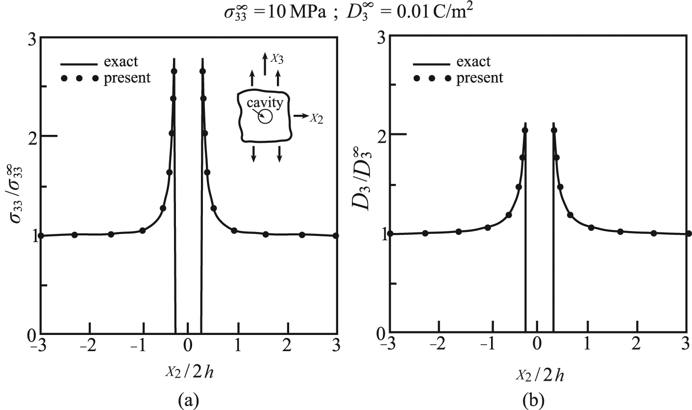
A circular cavity embedded in electromagnetoelastic medium
The first application considers a circular cavity of radius

where
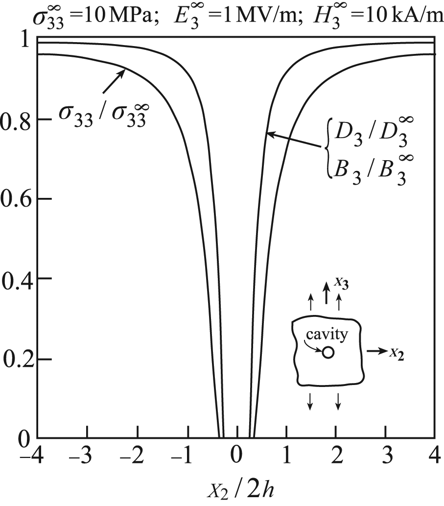
A cylindrical cavity embedded within an infinite
Periodically layered piezoelectric composite with a broken layer
Consider a periodically layered BaTiO3/cadmium selenide piezoelectric composite whose constituent properties are given in Tables 1 and 2 (see Figure 1(a) for configuration with
In the first one, the layered composite is loaded in the x2-direction with the crack of length
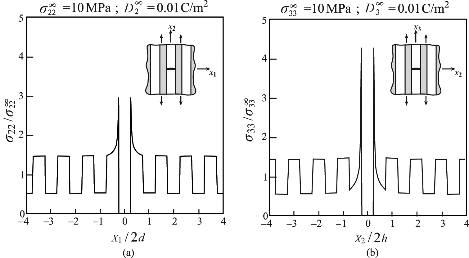
Transverse cracks in a periodically layered piezoelectric BaTiO3/cadmium selenide composite. The cracks are located in the cadmium selenide layer. (a) The stress variations along the crack’s line
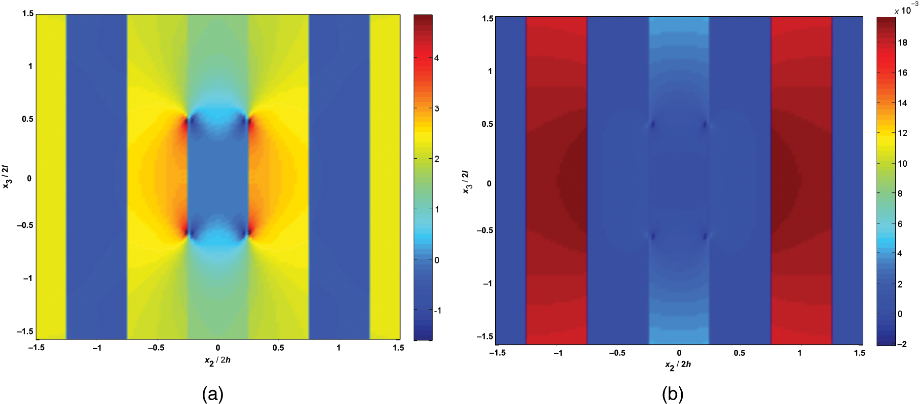
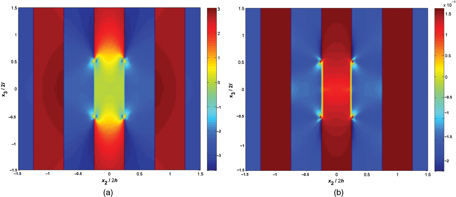
Periodically layered piezoelectric composite with an H-crack
Consider presently the same configurations that have been discussed in the previous application but this time with an H-crack in a cadmium selenide layer. The results from the two cases discussed earlier are presently generated and shown in Figure 10(a) and (b). In both cases,

H-crack in a periodically layered piezoelectric BaTiO3/cadmium selenide composite. The cracks are located in the cadmium selenide layer. (a) The stress
Periodically layered electromagnetoelastic composite with an H-crack
The periodically layered composite presently consists of
H-crack in a periodically layered electromagnetoelastic
Applied temperature in periodically layered piezoelectric composite with an H-crack
Thus far, all results were obtained under isothermal conditions, that is,
Thermal properties.
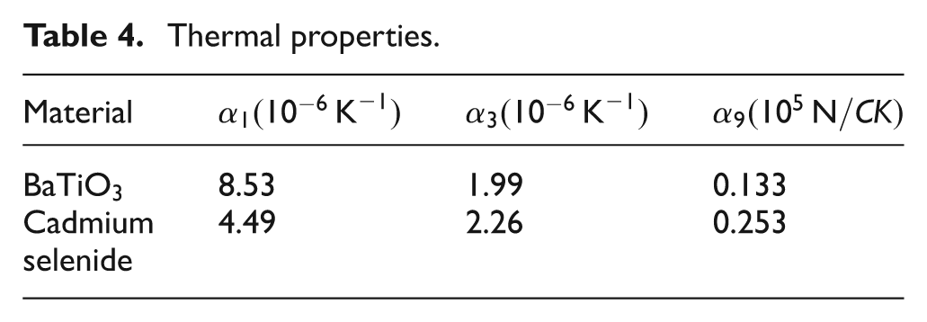
H-crack in a periodically layered piezoelectric BaTiO3/cadmium selenide composite. The cracks are located in the cadmium selenide layer. The applied uniform thermal loading is
Conclusion
A methodology has been presented that is capable to establish the field distributions of periodically layered electromagnetothermoelastic composites with damage in the form of cavities and cracks. The composites are subjected to arbitrary combined electric, magnetic, and mechanical loadings that must be sufficiently remote from the localized perturbed regions where cavities and cracks exist. This methodology is based on the combination of three distinct theories namely, the representative cell theory, the higher-order theory, and the HFGMC micromechanical model. The localized effects of the cavities and cracks appear in the constitutive equations of electromagnetothermoelastic material in the form of unknown eigenfield that necessitates the application of an iterative procedure until a convergence of the solution is achieved.
In addition, the present methodology enables the modeling of inclusions of any type (irrespective whether they are stiff or soft with respect to the surrounding matrix). This is based on the fact that the damage variables should always reduce their corresponding moduli (see equation (13)). Therefore, it is always required to define the given configuration with the largest moduli and apply the appropriate value of the corresponding damage variable that should reduce the modulus to its desired value in the considered region.
The method has been verified by a comparison with analytical solutions in five special cases. Several applications are presented, which show, in particular, the effect of H-cracks on periodically layered composites. The effect of these cracks is seen to be rapidly decaying. Thus, the theoretical assumption that the composite consists of infinite number of periodic layers is not a limitation, and the present approach can be utilized in practical situations.
Generalizations of the present method for the analysis of several localized interacting systems of cavities, cracks, and H-cracks are possible.
Footnotes
Funding
This research received no specific grant from any funding agency in the public, commercial, or not-for-profit sectors.