
Abstract
It has been observed that carbon nanotubes have a measurable inherent piezoresistive effect, that is to say that changes in carbon nanotube strain can induce changes in carbon nanotube resistivity, which may lead to observable macroscale piezoresistive response of carbon nanotube–polymer nanocomposites. In this article, the focus is on modeling the effect of inherent piezoresistivity of carbon nanotubes on the nanocomposite’s piezoresistive behavior using computational micromechanics techniques based on finite element analysis. Both in-plane and axial piezoresistive responses are being considered in an electromechanically coupled code. The computational results are used to estimate the magnitude of the piezoresistive coefficients of carbon nanotube needed for the piezoresistive response of macroscale nanocomposites to be comparable with experimental data in the literature. It is found that the current values for inherent piezoresistivity of the carbon nanotube are not sufficiently large enough to explain the observed macroscale piezoresistive response if inherent piezoresistive effect of carbon nanotubes is the only driving force for the piezoresistive response of the macroscale nanocomposites, and hence, additional mechanisms such as electron hopping and nanotube–nanotube contact may play important roles either individually or in a coupled fashion with inherent piezoresistivity of the carbon nanotube.
Introduction
To date, several types of carbon nanotube (CNT)–polymer nanocomposites have been shown to have linear piezoresistive responses with small loadings of single-walled carbon nanotubes (SWCNTs) or multi-walled carbon nanotubes (MWCNTs) (Bautista-Quijano et al., 2010; Ferreira et al., 2012a, 2012b; Kang et al., 2006, 2009; Oliva-Aviles et al., 2011; Zhang et al., 2006). Zhang et al. (2006) found in the small strain range of 1% that MWCNTs/polycarbonate (PC) films loaded with 5%wt MWCNTs can yield a strain sensitivity approximately 3.5 times that of a commercial (metallic) strain gauge. Kang et al. (2006) found the gauge factor of sensors made of SWCNT/poly(methyl methacrylate) (PMMA) composites to range from about 1 to 5 when the weight percentage of SWCNTs ranges from 0.5 to 10, with the higher sensitivity being achieved using 3–10%wt SWCNTs. Kang et al. (2009) reported that for the SWCNT/polyimide composite sensors, the maximum gauge factor is achieved at a concentration just above the percolation threshold concentration (0.05%wt SWCNTs) with a magnitude of 4.21. Bautista-Quijano et al. (2010) reported the gauge factors of thin films made of polysulfone (PSF) and dispersed MWCNTs to range from 0.48 to 0.73 when the weight percentage of MWCNT is between 0.2 and 1.0. Ferreira et al. (2012b) reported that the maximum gauge factor ranges up to 6.2 for the hot pressed SWCNT/polyvinylidene difluoride (PVDF) composites when the weight percentage of SWCNT is just below 2. For aligned MWCNT/PSF films with 0.5%wt MWCNTs aligned by application of alternating current (AC) electric fields during processing, Oliva-Aviles et al. (2011) reported a gauge factor of 2.78 ± 0.42 for tensile loading in the MWCNT alignment direction. It has also been observed that at a concentration just above the CNT electrical percolation threshold, the piezoresistive stress coefficient of SWCNT/polyimide nanocomposites exceeds those of metallic materials (aluminum) by two orders of magnitude (Kang et al., 2009). Such piezoresistive properties make CNT–polymer nanocomposites very attractive in the manufacturing of high–gauge factor lightweight strain gauges. In addition, CNT–polymer nanocomposite strain gauges have the potential to be directly embedded in structural composites during composite processing to provide internal strain sensing in contrast to the customary surface strain measurements obtained from commercial strain gauges bonded to the surface of structures. While there is ample experimental evidence demonstrating the piezoresistive response of nanocomposites, the mechanisms governing piezoresistivity of nanocomposites are less clear in terms of relative magnitude and interactions. In order to aid in the design of piezoresistive nanocomposite strain gauges with tailored sensitivities, it is necessary to develop an understanding of the underlying mechanisms at the micro- and nanoscales, which govern the macroscale piezoresistive response.
At present, several mechanisms are believed to contribute to the piezoresistive response of CNT–polymer nanocomposites. For example, Kang et al. (2009) have indicated that the piezoresistive response of macroscale nanocomposite material originates from the tunneling effect (Li et al., 2007) between conducting inclusions (CNTs) at the nanoscale under compression or tension. Fernberg et al. (2009) indicated that the geometric change of the specimen will have an effect on its macroscale resistance behavior.
An additional mechanism is associated with the CNTs themselves that have been shown to have a considerable inherent effect which should not be neglected. It has been observed both experimentally and in modeling that mechanical deformation of CNTs can directly lead to significant changes in their conductance (Peng and Cho, 2000), indicating that CNTs are themselves good strain sensors due to inherent piezoresistivity. Efforts to quantify the inherent piezoresistivity of CNTs have taken the form of both characterization and modeling experiments. For example, Chen et al. employed molecular dynamics simulations and quantum transport theory to study the electrical properties of (12, 0) zigzag CNTs under different uniaxial strains and found that a 1% strain can result in a 6.4% decrease in resistance (Chen and Weng, 2007). Tight-binding and zone-folding approximations have been used to predict the strain sensitivity of a CNT, which is found to be based on its chiral indices (n, m) and varies widely with the electrical structures (Anantram et al., 1999; Cullinan and Culpepper, 2010). Experimentally, Tombler et al. (2000) applied strain to a suspended CNT using atomic force microscopy (AFM) tips and observed that the conductance of the CNT could change by as much as two orders of magnitude under the applied strains. Stampfer et al. (2006) measured the relative differential resistance sensitivity for a metallic SWCNT of up to 27.5% per nanometer of deflection from which a piezoresistive gauge factor of an SWCNT of up to 2900 was extracted.
Analytic micromechanics multiscale methods such as self-consistent (Hill, 1965), Mori–Tanaka (Benveniste, 1987; Mori and Tanaka, 1973), and composite cylinder model (Hashin and Rosen, 1964) methods have been widely used to obtain the overall elastic, thermal, and electrical properties of heterogeneous materials. However, such analytic methods are generally limited to linear properties and in order to get solutions may have strict limitations on the geometries and physical properties of the constituent materials. In contrast, computational multiscale methods such as those based on multiscale expansion methods (Bakhvalov and Panasenko, 1989; Bensoussan et al., 1978) can overcome geometry and material property limitations and have been successfully applied for obtaining the overall nonlinear material properties, for example, load- and path-dependent effective properties involving plasticity and/or damage, and for solving various multiphysics problems (Fish et al., 1997, 1999; Yu and Fish, 2002). To date, analytic and computational multiscale methods have been applied toward predicting effective properties of various nanocomposites (see, e.g. the review article by Zeng et al. (2008) or other works including Odegard et al. (2003), Li and Chou (2003), Gates et al. (2005), Spanos and Kontsos (2008), Hammerand et al. (2007), Seidel and Lagoudas (2006, 2008, 2009), and Seidel and Puydupin-Jamin (2011), which have promising applications arising from the enhanced properties of nanoparticles.
However, for the observed linear, reversible, and path-independent piezoresistive response of the CNT–polymer nanocomposites, limited modeling work is found in the literature (Grimaldi et al., 2001, 2003; Hu et al., 2012; Li and Chou, 2008; Theodosiou and Saravanos, 2010; Wichmann et al., 2009). 1 For example, in studies of Grimaldi et al. (2001, 2003) and Li and Chou (2008), the focus was on the electrical tunneling effect on the macroscale piezoresistive response, while in the work of Wichmann et al. (2009), the focus was on purely geometric effects, with none of these works considering the inherent piezoresistive response of the CNTs. In another work (Hu et al., 2012), the focus has been on the inclusion of several mechanisms, including resistor network models and inherent CNT piezoresistivity in polymer nanocomposites with randomly oriented CNTs. Theodosiou and Saravanos (2010) found that the variation of CNT resistance with strain is the dominant mechanism for nanocomposite piezoresistivity, with a significant contribution also coming from the tunneling effect. In contrast, Hu et al. (2012) found that the inherent CNT piezoresistivity was not the dominant mechanism but rather that the resistive network and tunneling effects were driving the observed macroscale nanocomposite piezoresistive response. In fact, they note that with an average CNT gauge factor of 21.18, the overall piezoresistive response of the nanocomposite was only increased by roughly 9%. To our knowledge, there has been no clear discussion and quantification as to what magnitude of inherent CNT piezoresistivity is needed to achieve macroscale nanocomposite gauge factors on the order of 2–5 if this mechanism was indeed the driving force behind the nanocomposite piezoresistive response.
In this article, a computational multiscale micromechanics model based on finite element analysis is developed and used to determine the changes in macroscale resistance (i.e. effective macroscale piezoresistance) due to changes at the microscale associated with CNT deformation and inherent piezoresistivity. The effects of CNT geometry, local volume fraction, and inherent piezoresistive coefficients on the macroscale piezoresistivity are studied parametrically. The results are discussed in the context of experimentally observed gauge factors for nanocomposites and the strength of electromechanical coupling needed to achieve observed responses.
Model description
Multiscale model for the CNT–polymer nanocomposites
In the CNT–polymer nanocomposites, the strains in the CNTs may have an effect on their resistivities; therefore, the mechanical and electrical properties of the nanocomposites are one-way coupled. In other words, the mechanical properties of the domain may influence its electrical properties, but not vice versa. Typically, the dispersion and shape of CNTs in the CNT–polymer nanocomposites may be complicated, for example, the CNTs can be curved along their axes, randomly oriented, and bundled with the other CNTs. In order to focus the present study on the potential impact of inherent piezoresistivity of CNTs on the macroscale piezoresistive response of nanocomposites, we have selected a multiscale idealization as shown in Figure 1. In this representation, the CNTs are assumed to be well dispersed, aligned, and perfectly bonded to the surrounding polymer. The governing differential equations describing mechanical and electrostatic responses of the nanocomposites are given below.
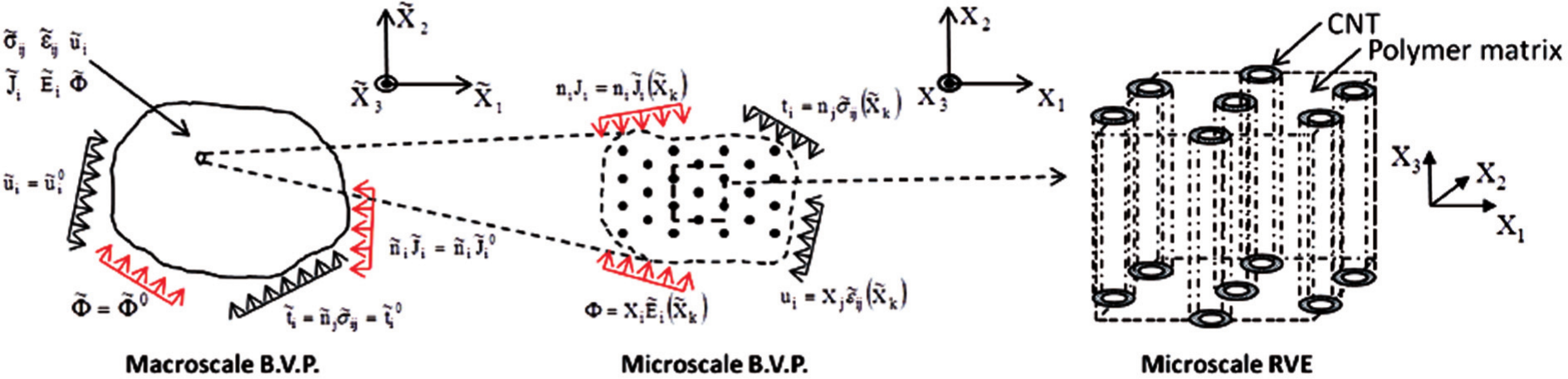
The hierarchical multiscale modeling of nanocomposites in which there are well-dispersed and aligned CNTs.
Mechanical governing differential equations at the macroscale
For quasi-static conditions and omitting body forces, conservation of linear momentum at the macroscale can be written in Cartesian coordinate system as
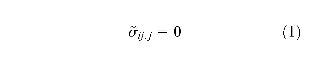
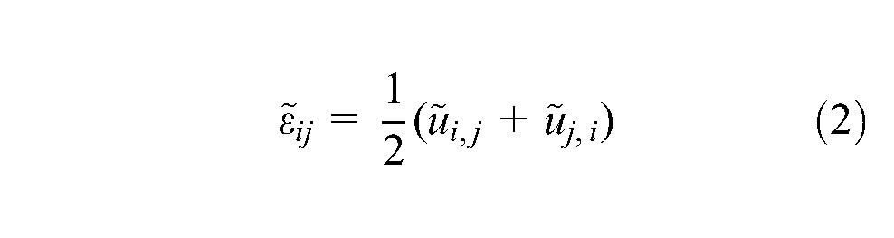
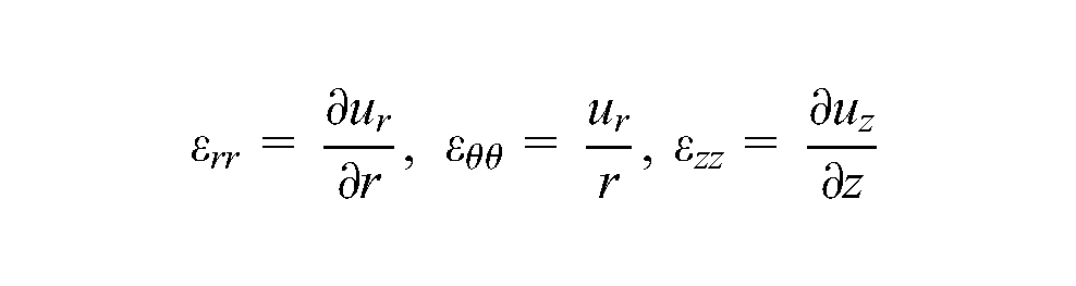
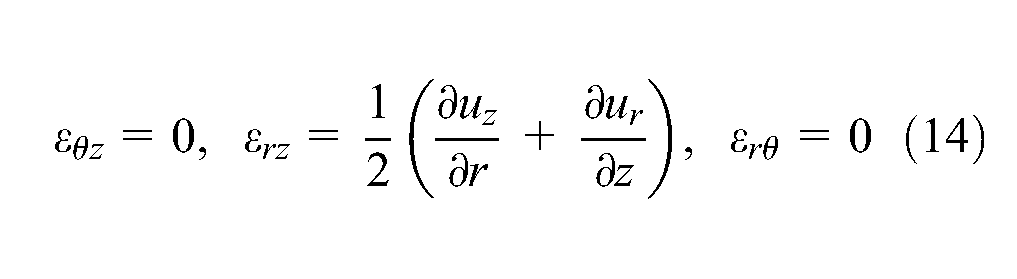
where the overscript “∼” denotes variables at the macroscale. Note that the summation convention is used with i, j ranging from 1 to 3 and the comma denotes spatial differentiation. The infinitesimal strain–displacement relations at the macroscale are given by
The macroscale constitutive relation for the mechanical boundary can be expressed as
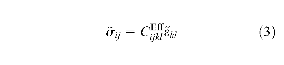
where
where the brackets
and
where the complete macroscale boundary is specified as the union of
Electrostatic governing differential equations at the macroscale
The steady-state conservation of charge equation at the macroscale can be written in Cartesian coordinate system as
where
where
or
where
or

where the brackets again denote volume averaging over the appropriate microscale RVE. The electrical boundary-value problem is completed through the specification of the boundary conditions given by
and
where the complete macroscale boundary is specified as the union of
Mechanical governing differential equations for the microscale RVE
The three-dimensional (3D) microscale RVE for aligned CNT nanocomposites (Figure 1) can be reduced to two 2D RVEs in order to save computational time. As seen in Figure 2(a), due to high aspect ratios (ARs) (
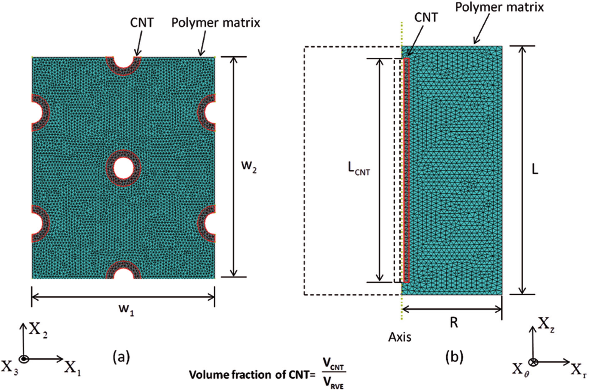
Microscale RVEs for the nanocomposites with well-dispersed and aligned CNTs. (a) The transverse hexagonal microscale RVE with the volume fraction of the CNTs being 10%. (b) The axisymmetric microscale RVE with the volume fraction of the CNTs being 0.5%vol and the aspect ratio of the CNTs being 20 (the aspect ratio used here is only for demonstration purposes as the real aspect ratio used in the computations is much higher (
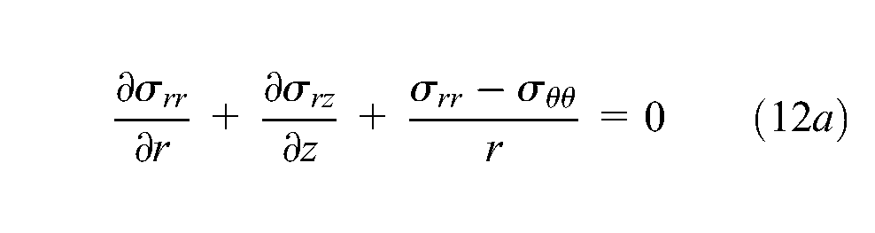
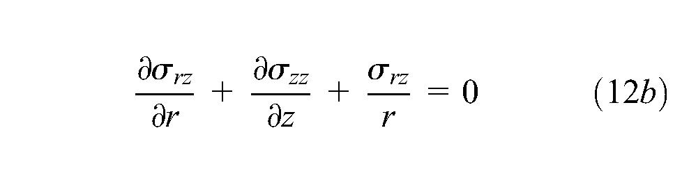
For quasi-static conditions omitting body forces, conservation of linear momentum for –the microscale RVE can be written in Cartesian coordinate system as
where under the plane strain assumptions of the transverse hexagonal RVE,
where it is noted that terms involving
where under the plane strain assumptions for the transverse hexagonal RVE,
At the microscale, the CNT annulus and polymer matrix can be assumed to be isotropic linear elastic materials (Saito et al., 1998) such that their constitutive relationships can be denoted with the Lame constants as
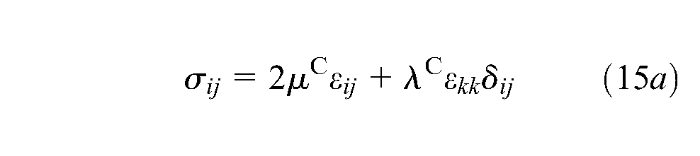
where the superscripts C and M on the material properties denote CNT and polymer matrix, respectively, and the standard relationships
such that in general the macroscale and microscale RVE stresses and strains can be related to one another through microscale volume averages as
where
Electrostatic governing differential equations for the microscale RVEs
The steady-state conservation of charge equation for the microscale RVE can be denoted in Cartesian coordinates as
where
where it is noted that terms involving
where
where it is noted that terms involving the differentiation with respect to
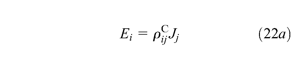
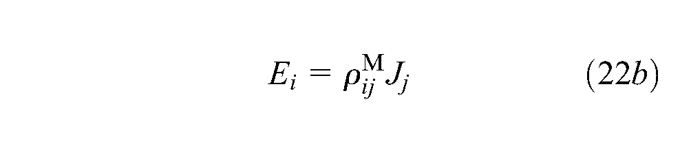
where the superscripts C and M on the resistivities denote CNT and polymer matrix, respectively, such that the inverses of equations (22a) and (22b) yield the electrical conductivities of the CNT and polymer matrix, respectively, as
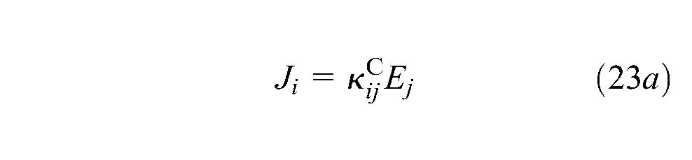
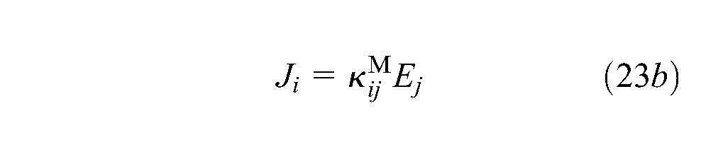
Note that in equations (22) and (23),
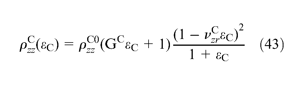
As the pure polymer matrix is not expected to be piezoresistive, the resistivity remains fixed under the applied strains. However, the CNTs are expected to exhibit inherent piezoresistivity such that the instantaneous resistivity,
in which
The
one may write

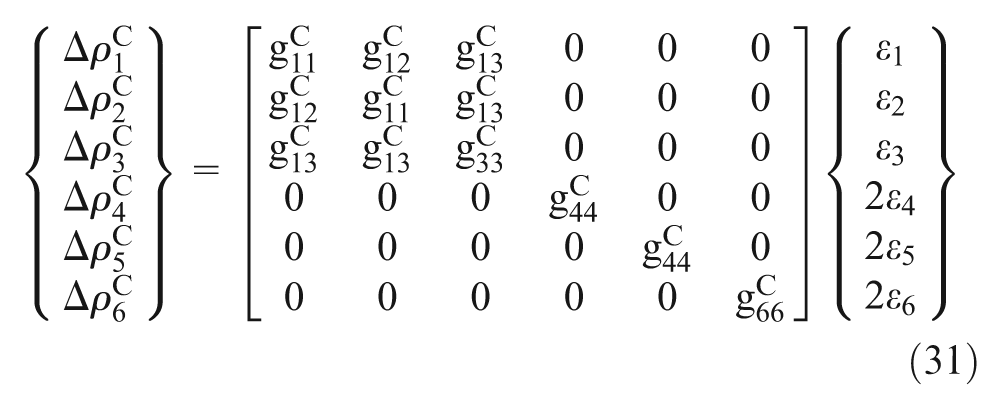
The piezoresistive constitutive equation can therefore be denoted in Voigt notation as
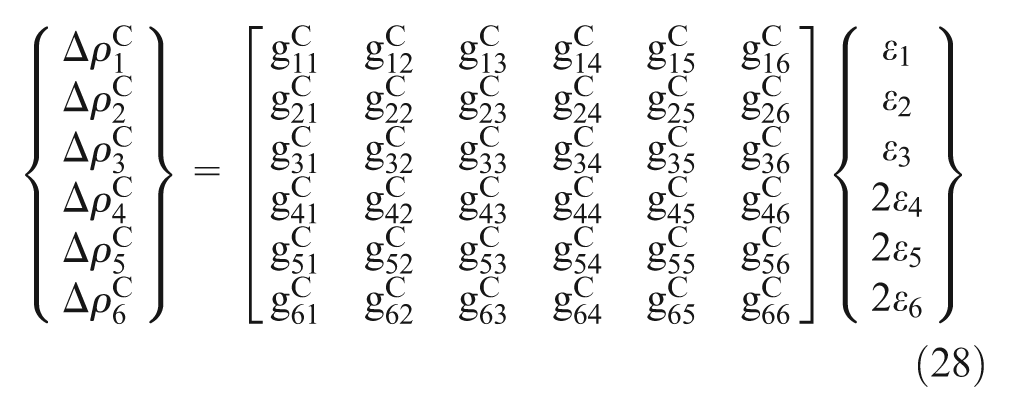
in which the number of the piezoresistive strain coefficients

Similarly, in equation (28) the Voigt notation correspondence in cylindrical components is given by

Based on CNT geometry and composition, 2 the CNT piezoresistive strain coefficients are at most of transversely isotropic symmetry and can therefore be expressed as
The number of independent components of the
such that in general the macroscale and microscale RVE current densities and electric fields can be related to one another through microscale volume averages as
where
Boundary conditions and effective properties
Mechanical boundary conditions
The macroscale material’s effective elastic material properties can be obtained by constructing strain energy equivalence between the microscale RVE and the effective homogeneous representation using homogeneous periodic mechanical boundary conditions (Bensoussan et al., 1978). In the present work, periodic displacement boundary conditions consistent with certain desired uniform macroscale strain states are applied to the microscale RVEs that are known to be good representations for aligned well-dispersed fiber arrangements. The uniform strain fields chosen here are consistent with those present in macroscale plane strain tension tests and uniaxial tension test, which could be used to get effective elastic properties for the nanocomposites from the volume-averaged stress and strain relationships provided in equation (4) (Hammerand et al., 2007). Herein the focus is on the piezoresistive effect, thus the choice of the tests are to demonstrate the magnitude of the impact of different strain states on the effective piezoresistive response of the nanocomposite material. The detailed periodic mechanical boundary conditions are listed in Table 1.
Boundary conditions for the 2D microscale RVEs as shown in Figure 2(a) and (b).
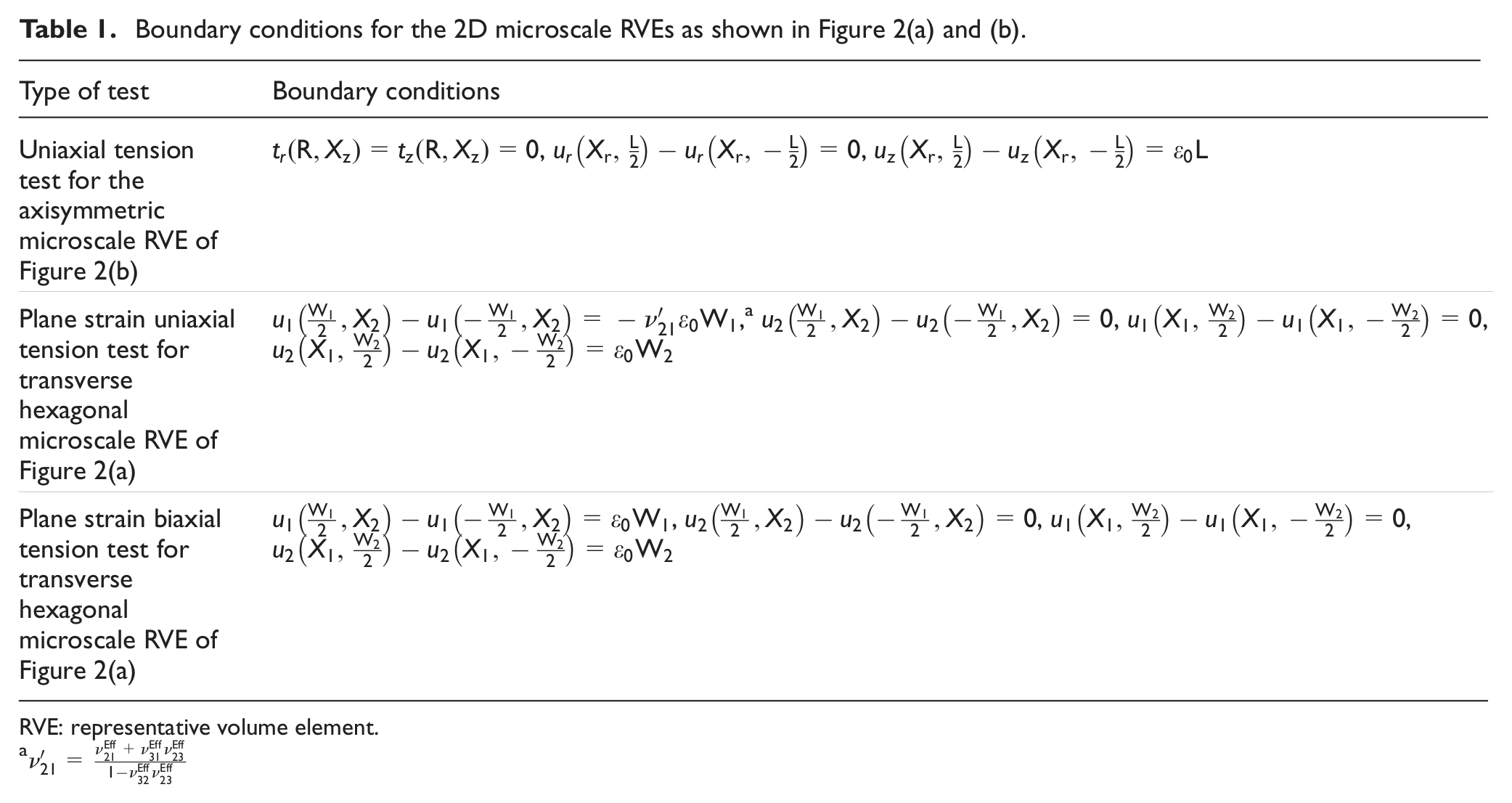
RVE: representative volume element.
It can be noted that under the in-plane strain assumption, the displacement field components
In general, the effective elastic properties can be obtained from the strain energy equivalency between the microstructural representation (i.e. the RVE) and an effective homogeneous material having the same exterior geometry and boundary conditions. The equivalency can be expressed as
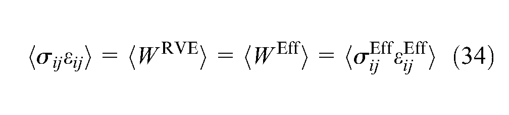
where
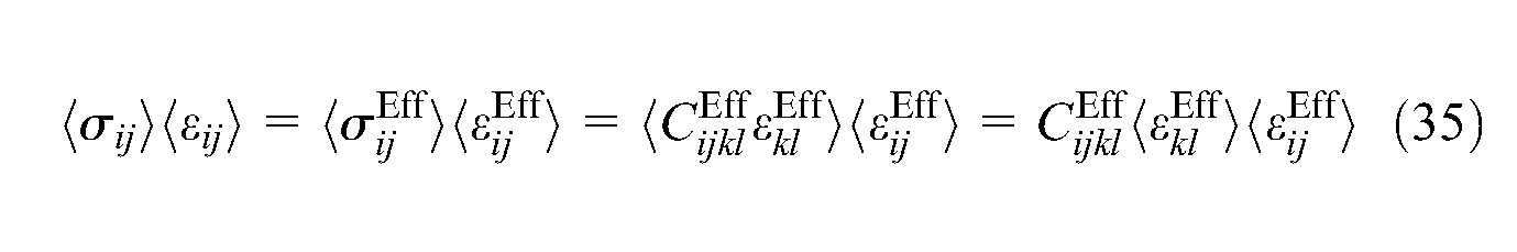
As both the microstructural RVE and effective homogeneous representation are subjected to the same displacement boundary conditions,
Electrostatic boundary conditions
In an analogous manner as in the mechanical problem, the macroscale material’s effective electrostatic material properties can be obtained by constructing electrical energy equivalence between the microscale RVE and the effective one with homogeneous periodic electrical boundary conditions applied. In the present work, periodic potential boundary conditions consistent with certain desired uniform electric field states are applied to the microscale RVEs, as listed in Table 2.
Electrostatic boundary conditions for obtaining the effective electrical conductivities.
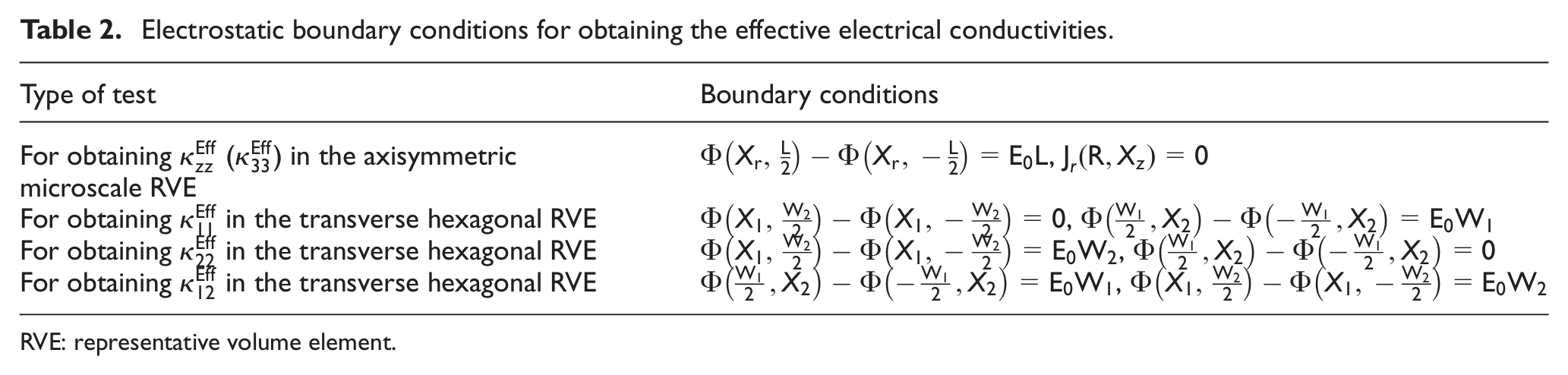
RVE: representative volume element.
Under the in-plane electrostatic assumption, the potential field
In general, the electrical conductivities can be obtained from the electrical energy equivalency between the microstructural representation (i.e. the RVE) and an effective homogeneous material having the same exterior geometry and boundary conditions. The equivalency can be expressed as
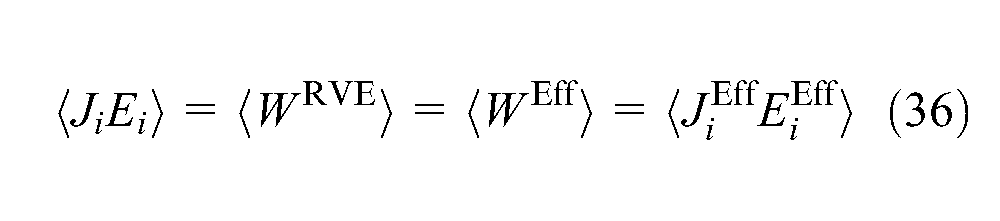
where
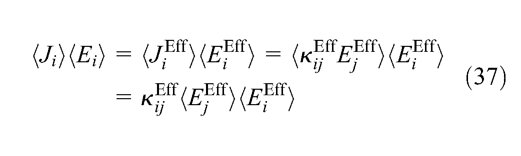
As both the microstructural RVE and effective homogeneous representation are subjected to the same potential boundary conditions,
Piezoresistive algorithm
An incremental algorithm for determining the piezoresistive response of the nanocomposites is developed within a finite element framework and is applied to the 2D microscale RVEs as shown in Figure 2. The Galerkin and Ritz methods are used, respectively, for the formulation of in-plane and axisymmetric piezoresistive finite element models. The mechanical and electrostatic finite element formulations are coupled together sequentially with the mechanical formulation used to first obtain the strains in the microscale RVEs, which are then used as inputs for the electrostatic formulation. The detailed piezoresistive algorithm is provided in Figure 3.
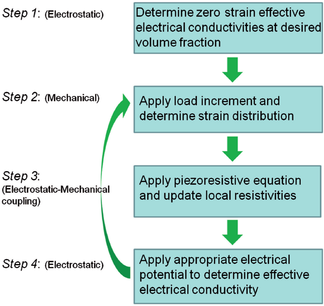
The piezoresistive algorithm of the finite element model.
In step 1 of the algorithm, the electrostatic potential boundary-value problems as identified in Table 2 are applied to the initial undeformed microscale RVEs resulting in potential distributions, and the electrical energy equivalence is used to obtain the conductivities of the effective microscale RVEs. In step 2, the first mechanical load increments are applied to the microscale RVEs according to the boundary conditions identified in Table 1, resulting in the local strain distributions. In step 3, the local strains in the CNT obtained from step 2 are used in the piezoresistive constitutive relation to determine changes in the local resistivities of the CNTs. In step 4, the same electrostatic potential boundary-value problems from step 1 are applied again to the microscale RVEs with updated local electrical properties of the CNT, with the electrical energy equivalency enforced to obtain the effective conductivities
In order to compare with measures more commonly used in experiments, the effective resistivities
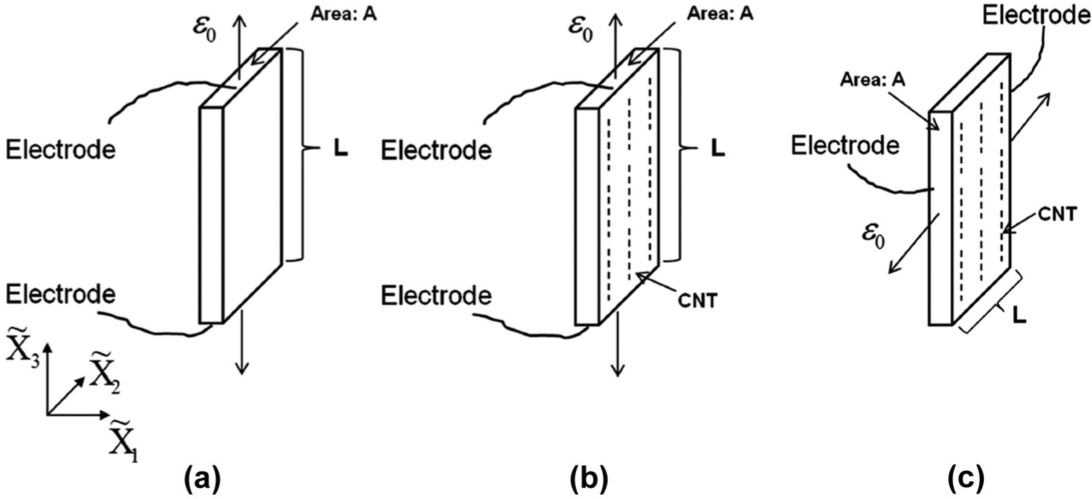
Schematic representation of the calculation of macroscale gauge factors for (a) a general uniaxial tension test, (b) a uniaxial tension test in the alignment direction of an effectively transversely isotropic nanocomposite, and (c) a uniaxial tension test in the transverse direction of an effectively transversely isotropic nanocomposite.
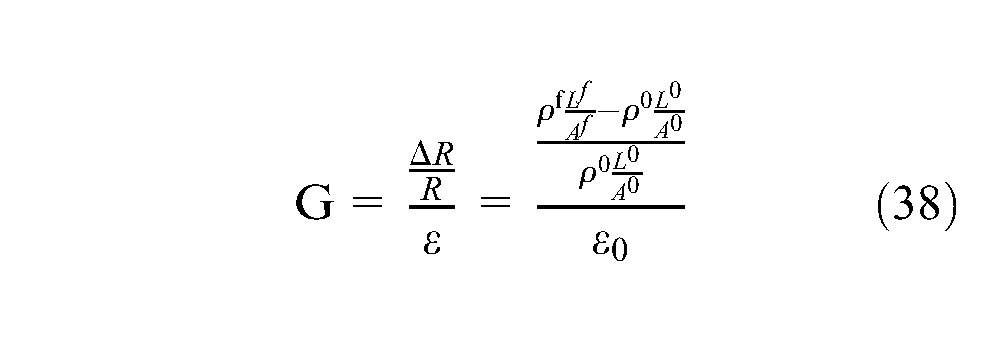
where G is the gauge factor,
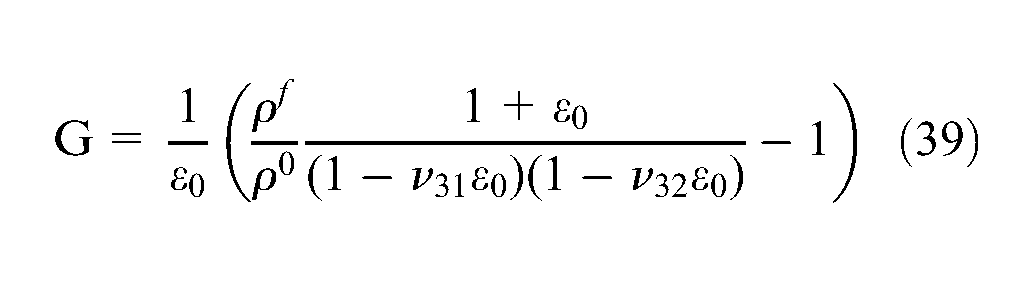
For the metal alloy wires commonly used in strain gauges, the initial and final resistivities are the same, so that the gauge factor is governed by the isotropic Poisson’s ratio and results in an approximately linear relationship between normalized change in resistance and strain (i.e. with G as the slope of the curve) for small strains.
However, the inherent piezoresistivity of the CNTs means that the initial and final resistivities of the nanocomposite will differ from one another, introducing additional nonlinearity in the gauge factor. As such, the effective gauge factor for the nanocomposite as obtained from a uniaxial tension test in the CNT alignment direction (i.e. from the axisymmetric RVE) would be determined as
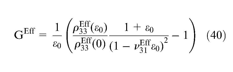
where the transverse direction is the isotropic plane such that
Similarly, for the transverse plane strain symmetric biaxial tension case, equation (38) becomes independent of the effective Poisson’s ratios and is given by
Results and discussion
The polymer matrix used in the model is the epoxy resin EPON 828, which is assumed to be isotropic linear elastic below its glass transition temperature. The detailed mechanical, electrical, and geometric parameters of the CNT and EPON 828 matrix are listed in Table 3.
Mechanical, electrical, and geometric parameters for the CNT and EPON 828 polymer matrix (Arris, 2000; Ebbesen et al., 1996; Hammerand et al., 2007; Schadler et al., 1998; Seidel and Lagoudas, 2009). The conductivity of the CNT listed here is the initial conductivity with zero strain.
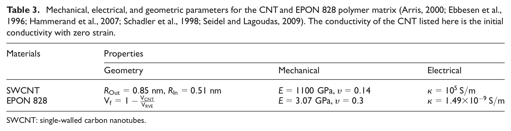
SWCNT: single-walled carbon nanotubes.
Experimental efforts have demonstrated that the gauge factor of a single metallic SWCNT (
where it has been understood that the experimental conditions are most reflective of uniaxial tension of the CNT along the CNT axis. Applying the piezoresistive constitutive equation and solving for the axial piezoresistive strain coefficient, one obtains
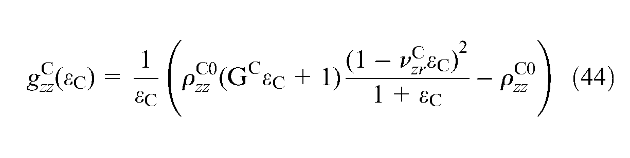
Using the data from Table 3 and the gauge factor of 2900 and CNT strain value of
Nanocomposite piezoresistive response under uniaxial tension in the CNT alignment direction
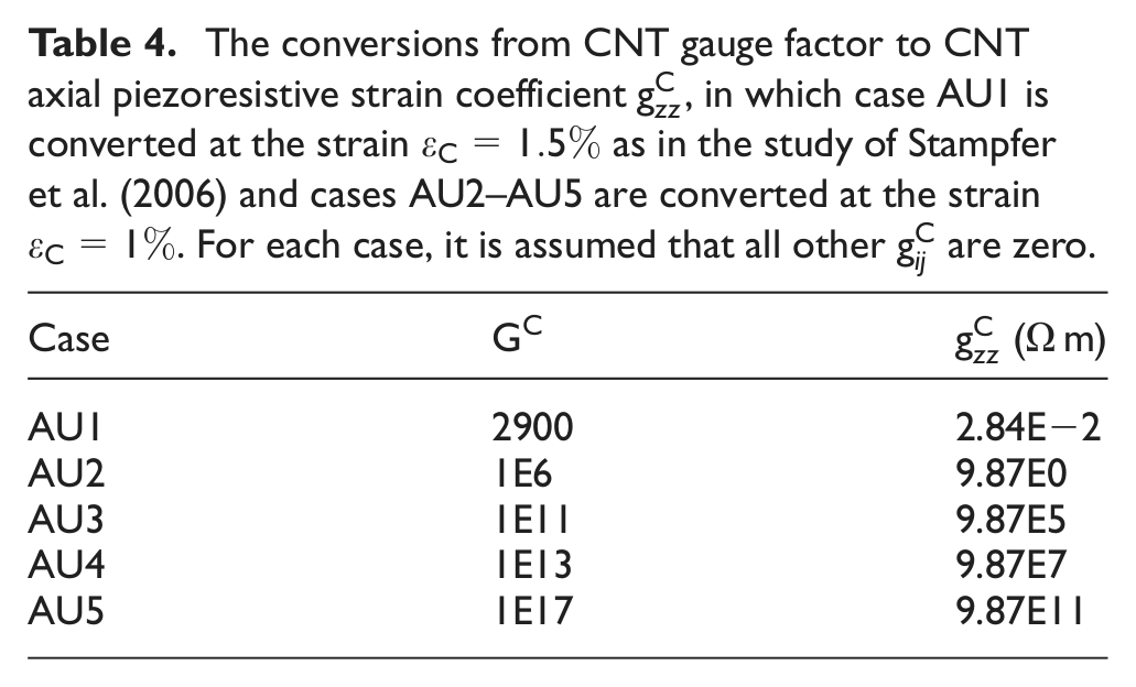
The axisymmetric microscale RVE is used to parametrically assess the influence of CNT gauge factor on the macroscale piezoresistive response of nanocomposites in tension in the CNT alignment direction. Five CNT gauge factors are considered, with the first case corresponding to the experimentally reported CNT gauge factor. The CNT gauge factors and their corresponding axial piezoresistive strain coefficients are provided in Table 4. It is noted that in order to focus on the dominant strain component’s impact on piezoresistivity, it is assumed that only the axial piezoresistive strain coefficient is nonzero.
The conversions from CNT gauge factor to CNT axial piezoresistive strain coefficient
The evolution of local strains and resistivities under applied macroscale strain increments are provided in Figure 5 for a CNT volume fraction of 0.20 and AR (

The evolution of local strains and resistivities under applied macroscale strain increments for a CNT volume fraction of 0.20 and aspect ratio of 5 and for a CNT gauge factor corresponding to case AU1. A potential difference of 1 V is applied between the top and bottom edge of the microscale RVE. The results are shown in the form of contour plots of the axial strain component
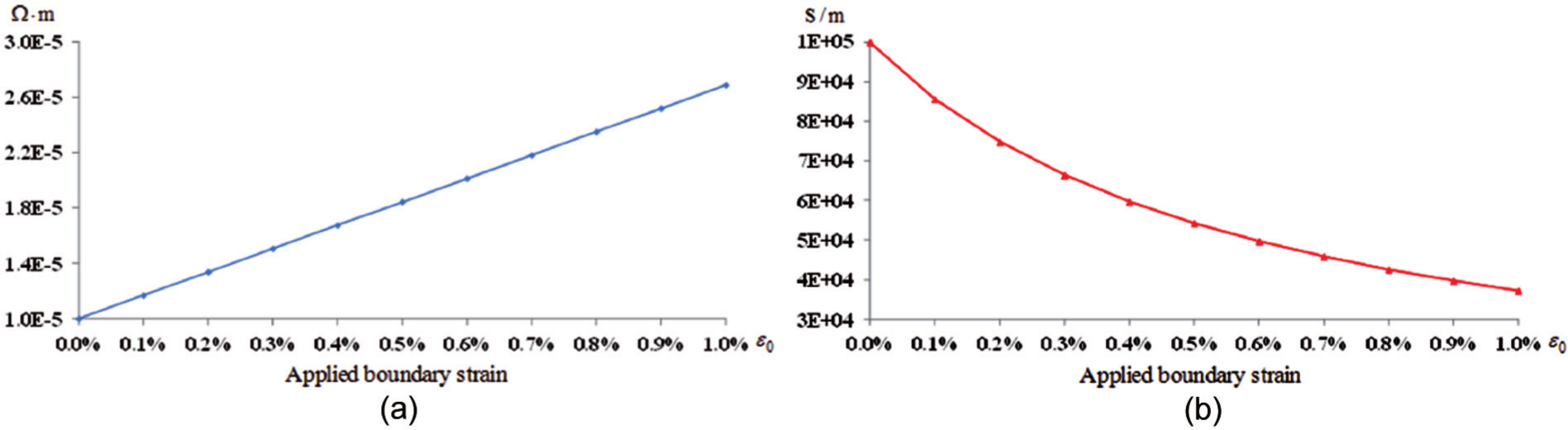
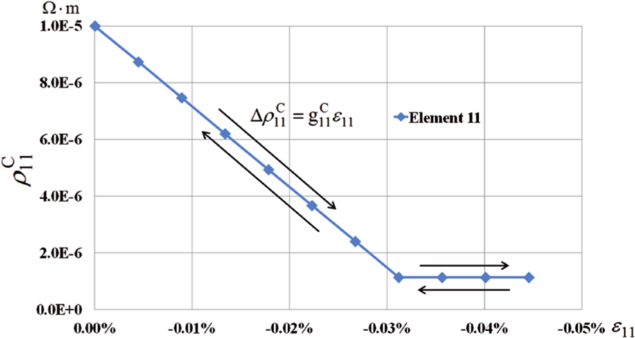
The change of electrical properties within an element of the CNT in response to the applied boundary strain,
Having demonstrated successful implementation of the piezoresistive algorithm, the remaining results focus on nanocomposite effective piezoresistive response for CNT having higher ARs (e.g. 50, 100, 200, 300, 1000, 3000, and infinite) and at CNT volume fractions of 0.005, 0.01, 0.05, and 0.10. It is noted that common SWCNT ARs range between 300 and 600 and, in some cases, to more than 1000. It is also noted that the vertical separation between the end of the CNT and the boundary of the axisymmetric RVE is set to be consistent with the maximum allowable separation at the CNT AR of 1 for every given volume fraction. The separation is then held constant for higher ARs so that in the limit case, the radius R becomes one of the infinite cases of which the transverse hexagonal RVE is a good approximation.
The influence of the CNT gauge factor on the change in effective axial resistivity component as a function of applied boundary strain, that is,
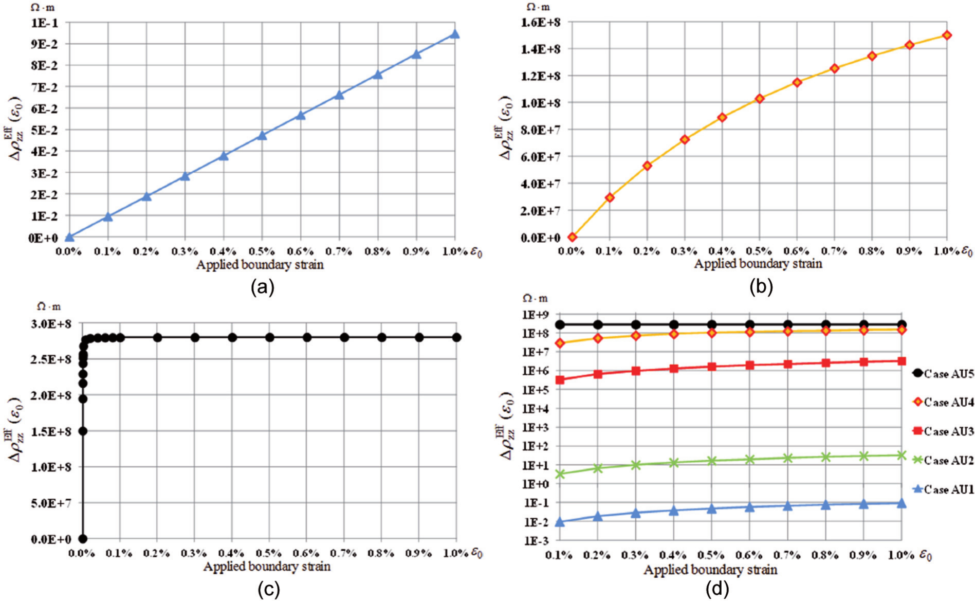
Nanocomposite effective axial resistivities
The effects on the piezoresistive response of the nanocomposite of increasing the AR of the CNTs at a fixed volume fraction of 0.01 are provided in Figure 8 for CNT ARs of 50, 100, 200, 300, 1000, and 3000 and for the infinitely long (i.e. continuous) CNT case for the CNT gauge factor of AU3. In Figure 8(a), the difference in the volume-averaged resistivity of the CNT relative to its zero strain value, that is,
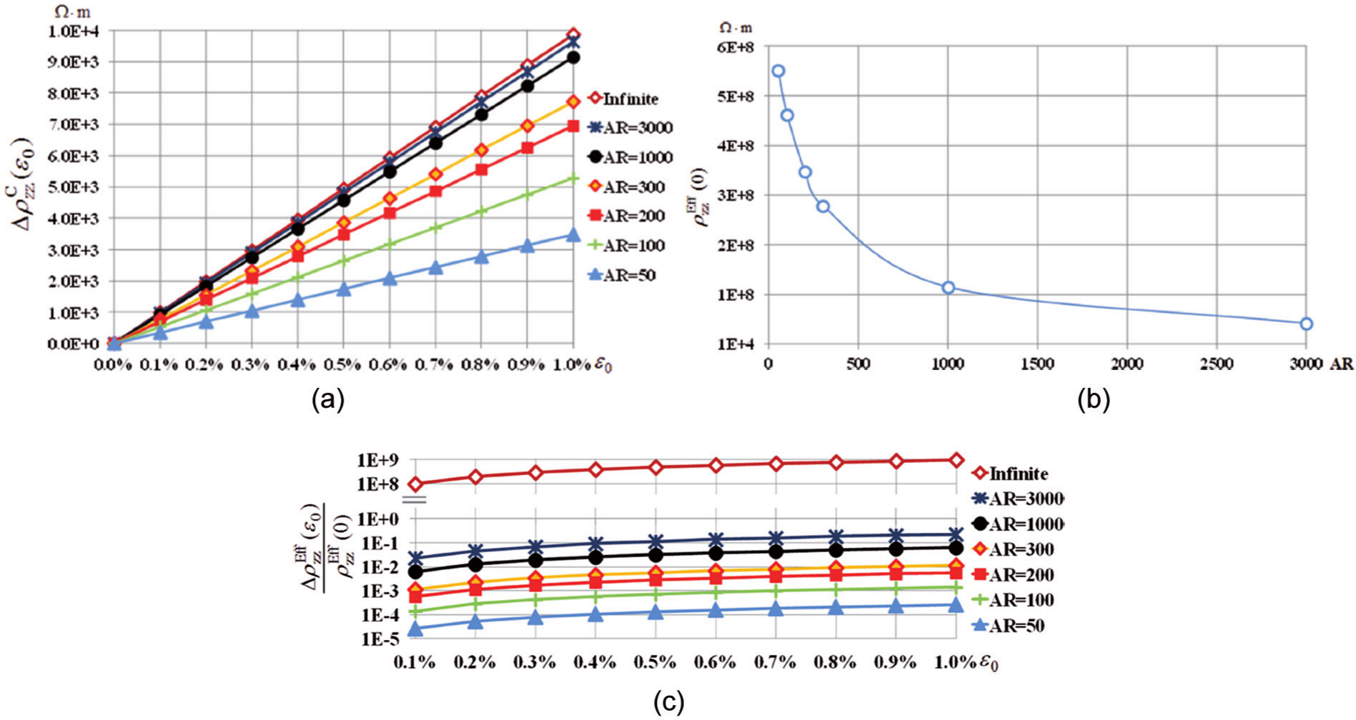
The effect of AR of the CNT on the effective electrical properties of the nanocomposites for a CNT volume fraction of 0.01 and CNT gauge factor of case AU3 (
The influence of CNT volume fraction on the effective piezoresistive response of the nanocomposite to applied uniaxial strain in the CNT alignment direction is provided in Figure 9 for a fixed CNT AR of 300 and for CNT gauge factors corresponding to cases AU3 and AU4. As the strains within the CNT vary by only a small amount (
The relative change of the effective axial resistivities of the nanocomposites in response to the applied boundary strain
Comparison between the results obtained from the axisymmetric FEM for the infinitely long CNT case with results from CCM where the CNT resistivity has been modified according to the piezoresistive constitutive equation based on the applied strain and a CNT gauge factor of
It is observed that with a higher volume fraction of the CNT, the initial effective resistivity is lower and the curve increases more slowly than the ones with a lower volume fraction of the CNT, which behaves differently than the results of the transverse piezoresistive response. This is because the initial effective resistivity is directly influenced by the volume fraction of the CNT, and with a higher volume fraction, the effective resistivity can be lower; on the other hand, the slope of the curve is influenced by the strain level within the CNT, and with a higher volume fraction, the strains within the CNT are lower, causing the curves to increase less rapidly.
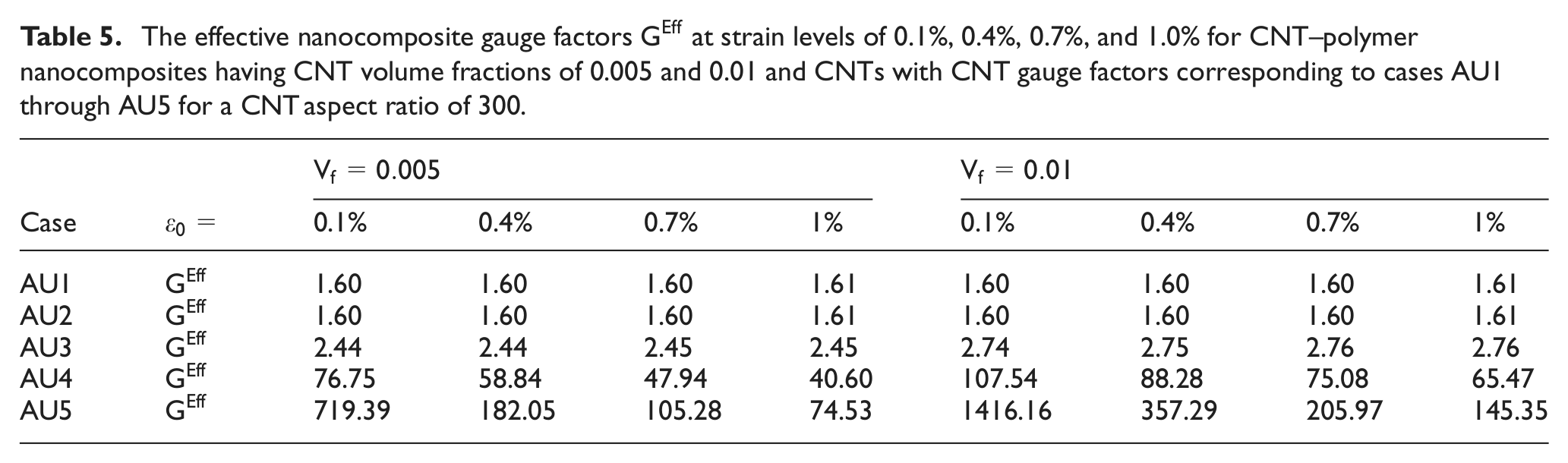
By applying equation (40), one can obtain the effective gauge factors of the nanocomposites,
The effective nanocomposite gauge factors
Results for the transverse piezoresistive response of the nanocomposites
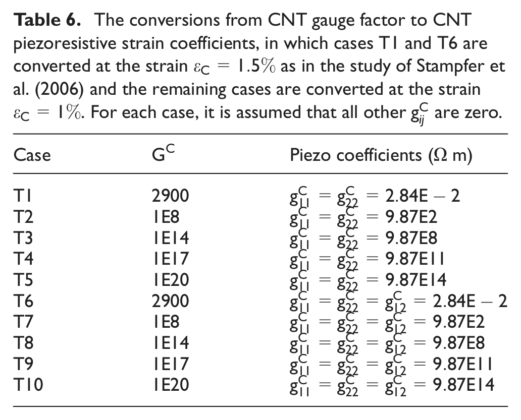
The transverse microscale RVE is used to parametrically assess the influence of CNT inherent piezoresistivity on the macroscale piezoresistive response of nanocomposites in the transverse directions with respect to CNT alignment direction. As noted in section “Introduction,” the majority of data regarding inherent piezoresistivity of CNTs is limited to axial testing. As such, there are little data available regarding the remaining independent piezoresistive strain coefficients needed to fully characterize the transversely isotropic piezoresistive response of the CNT. As such, two reduced sets of CNT piezoresistive strain coefficients in the transverse direction are considered. In the first set, the normal strain response are equally weighted in terms of piezoresistive strain coefficients but are decoupled, that is,
The conversions from CNT gauge factor to CNT piezoresistive strain coefficients, in which cases T1 and T6 are converted at the strain
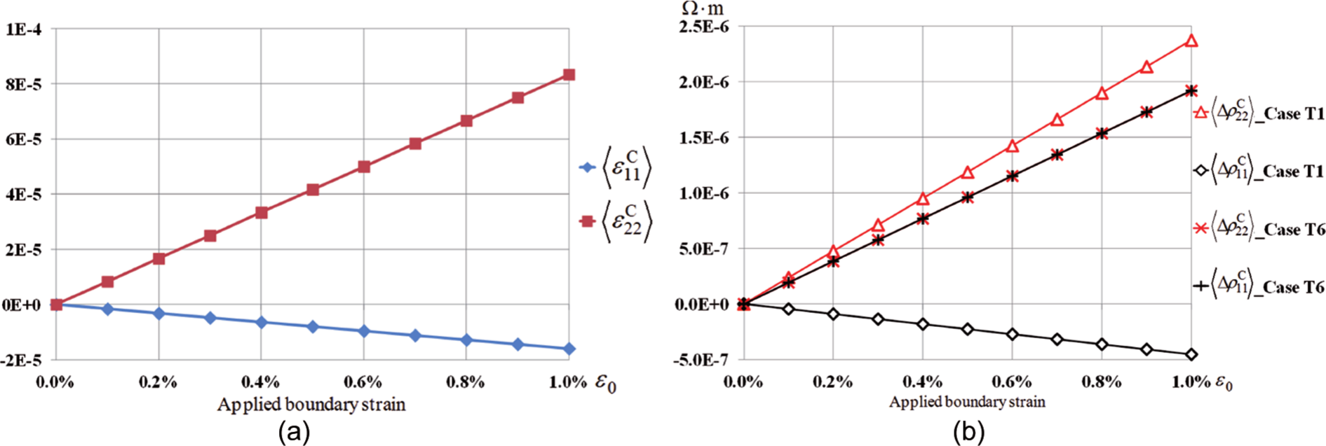
The distributions of local strain and resistivity components of the plane strain uniaxial tension in the 2-direction test are provided in Figure 11 for a CNT volume fraction of 0.60 and for CNT piezoresistive strain coefficients corresponding to cases T1 and T6, respectively.
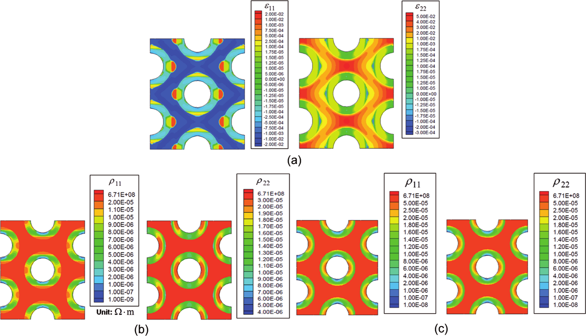
The distribution of local strains and resistivities of the plane strain uniaxial tension in the 2-direction test at
The contour plots demonstrate the direct correspondence between changes in local strains in the CNTs and changes in the local CNT resistivities, while the local matrix resistivity remains unchanged despite changes in local strains. In Figure 11(b), one can observe that
The CNT resistivity component
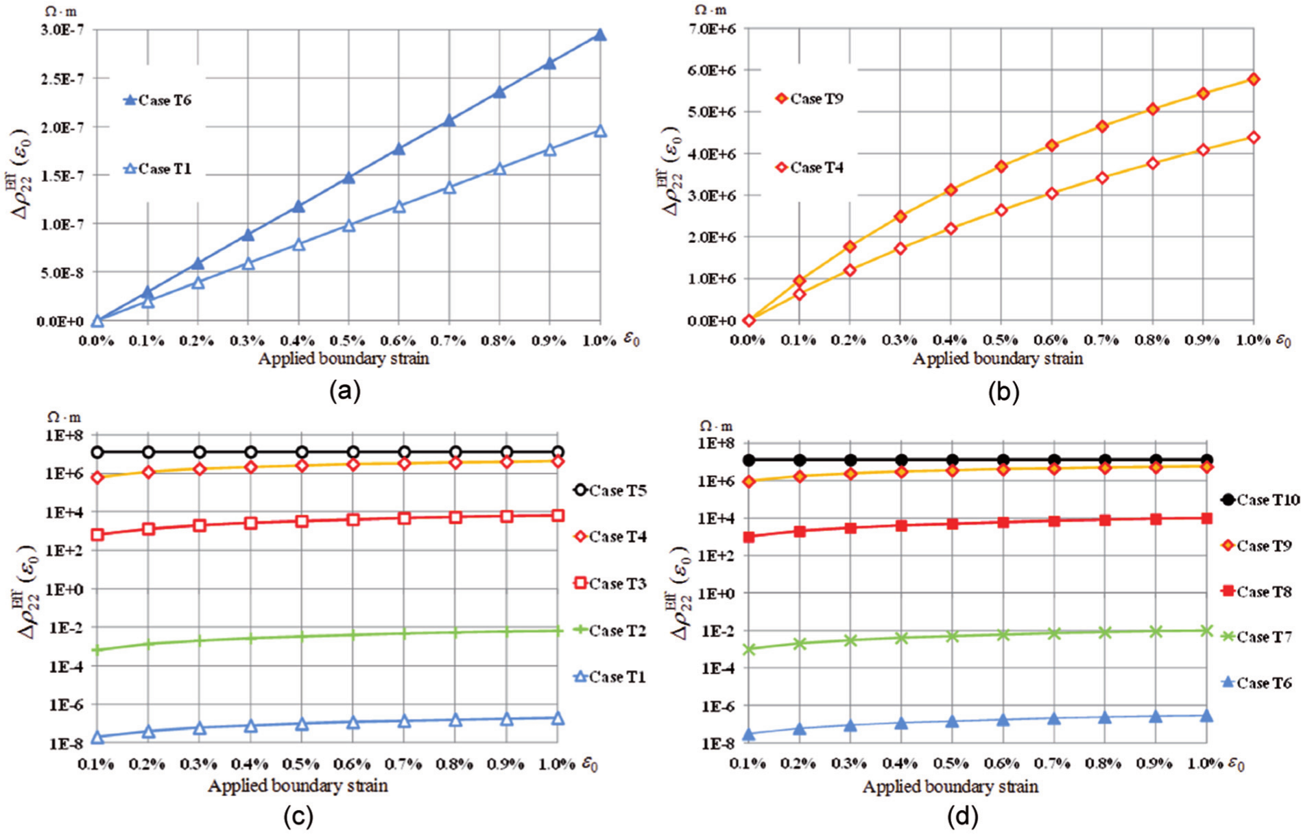
Having demonstrated the implementation of the piezoresistive algorithm, the remaining results focus on nanocomposite effective piezoresistive response for CNT having lower volume fractions (e.g. 0.005, 0.01, 0.05, and 0.10). The influence of CNT piezoresistive strain coefficients on the change in effective resistivity component
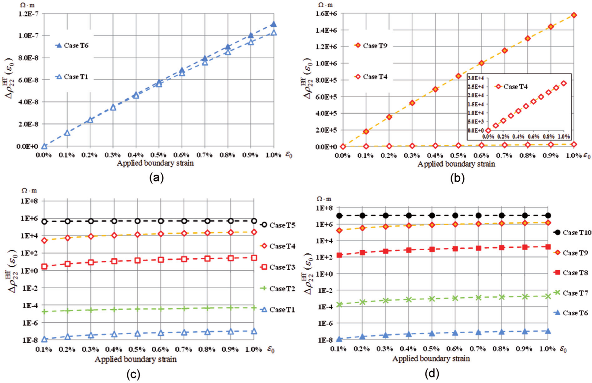
Nanocomposite effective transverse resistivity component
In comparing the response in Figure 13(a) to the piezoresistive response of the nanocomposite to uniaxial tension in the axial direction provided in Figure 7(a), one can observe that
In Figure 13(c) and (d), one can also observe that
(a) The volume-averaged strain components
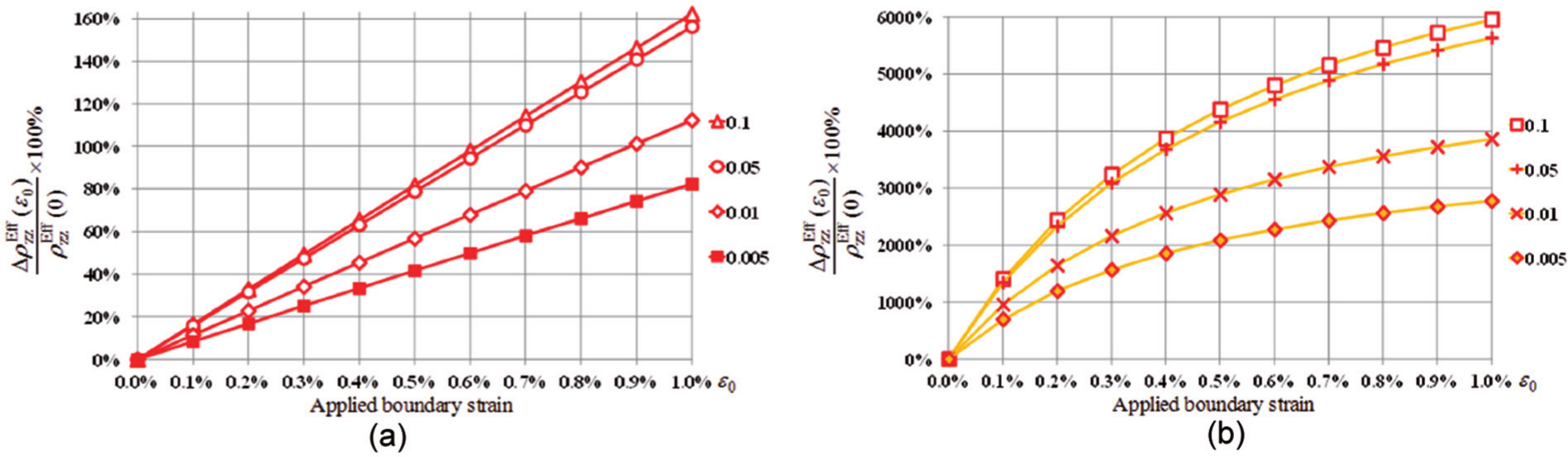
The influence of CNT volume fraction on the effective piezoresistive response of the nanocomposite to the applied strain in the plane strain uniaxial tension in the 2-direction test is provided in Figure 15 for CNT gauge factors corresponding to cases T8 and T9. Similar to what was observed in the axisymmetric uniaxial tension test, large differences in the sensitivity of the nanocomposite piezoresistive response can be observed, with the higher volume fractions being more sensitive to the applied strain than the lower volume fractions. In Figure 15(a), case T8 is observed to yield a seemingly linear normalized piezoresistive response at all volume fractions considered, with the volume fraction of 0.10 demonstrating much higher sensitivity than the volume fraction of 0.005 by roughly 31.7 times. The same trend in terms of higher volume fractions yielding higher sensitivities is again observed in Figure 15(b) for case T9; however, the sensitivities are three orders of magnitude higher than the T8 case and demonstrate a slightly nonlinear response. However, when compared with the sensitivities observed in the axial direction, the sensitivities observed in the transverse uniaxial tension test are orders of magnitude smaller even for CNT gauge factors, which are orders of magnitude larger and include off-diagonal terms. This is due to the matrix dominance of effective properties in the transverse direction that leads to reduced influence of changes in the CNT and to zero strain resistivities
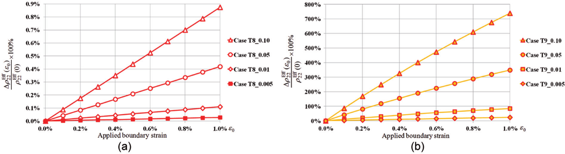
The relative change of the effective resistivity components
The results of the plane strain biaxial tension test are shown in Figure 16. By comparing with the results of plane strain uniaxial tension test in Figure 13, one can observe that for cases T1 through T10, the changes in effective resistivity component
Nanocomposite effective transverse resistivity component
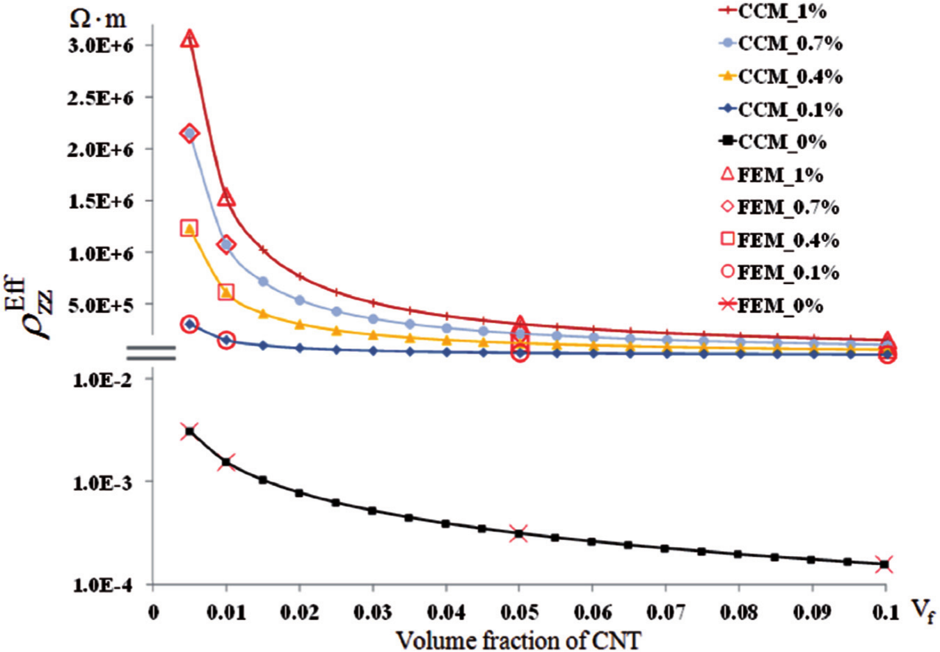
It is noted that for the plane strain biaxial tension cases, the strain field in the CNT is nearly uniform, so that for both the T1–T5 and the T6–T10 cases, the resistivity in the CNT remains nearly uniform and isotropic. As such, it is possible to use the volume-averaged resistivity of the CNT at the various strain levels in a composite cylinder model and construct a comparison with the finite element results for the change in resistivity with applied strain as provided in Figure 17 for case T9. From Figure 17(a), it is observed that as the strain level increases, the slopes of the resistivity versus volume fraction curves obtained from the composite cylinder model rapidly increase in a nonlinear fashion such that there is greater divergence between strain levels with increasing volume fraction. Converting these data into the change in resistivity as a function of applied strain and overlaying with the finite element results, a very good correspondence is obtained between the two models indicating that the nonlinearity observed in the finite element results is consistent within the micromechanics framework and therefore applicable to other loading states where tools such as the composite cylinder model cannot be used due to the nonuniformity and material symmetry distribution within the CNT, for example, the plane strain uniaxial tension or in-plane shear loadings.
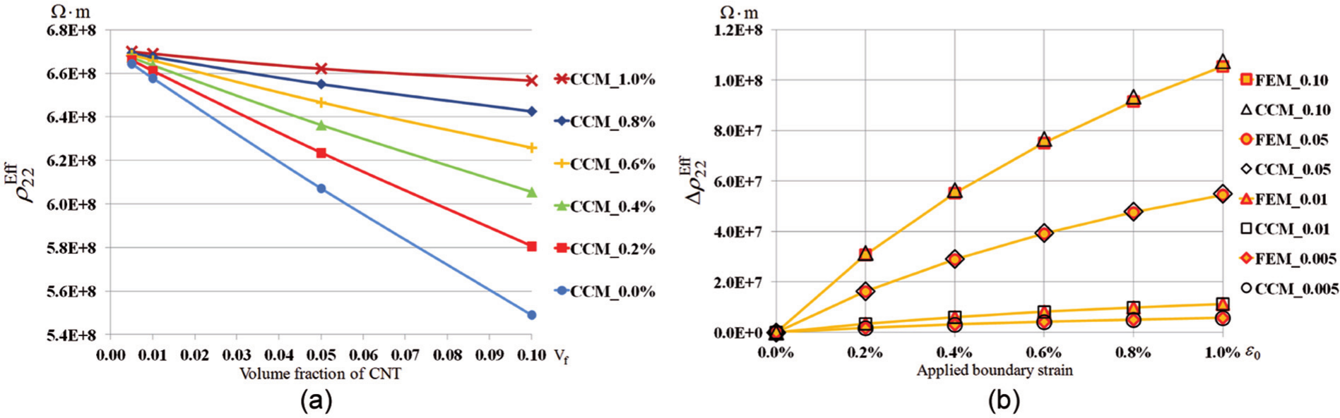
Comparison between the results obtained from FEM with results from CCM for case T9 of the plane strain biaxial tension test, where in the CCM model, the CNT transverse resistivity has been modified to the volume-averaged resistivity based on applied strains on the CNT. (a) The effective resistivity component
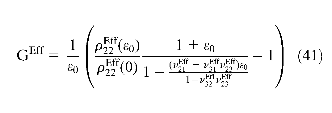
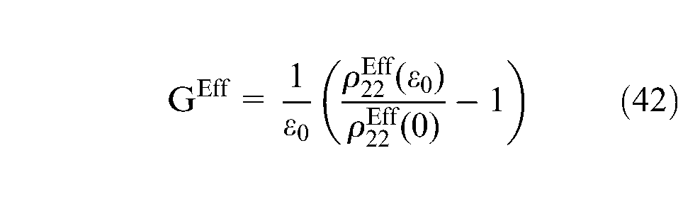
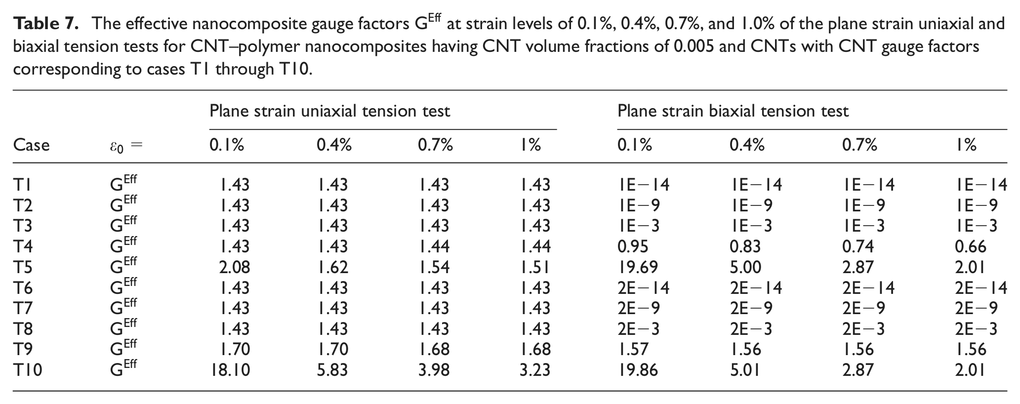
By applying equations (41) and (42), one can obtain the effective gauge factors of the nanocomposites,
The effective nanocomposite gauge factors
Conclusion
Computational micromechanics models are constructed to assess the piezoresistive responses of aligned CNT–polymer nanocomposites in the axial and transverse directions due to the inherent piezoresistivities of CNTs, which are assumed to be well dispersed and perfectly bonded to the surrounding polymer. A parametric study in terms of CNT gauge factor, AR, and volume fraction is undertaken to study the influence of these factors on the effective nanocomposite piezoresistive response and gauge factors under uniaxial loading in the axial and transverse directions and symmetric biaxial tension in the transverse direction. The results of the axisymmetric piezoresistive model show that through a combination of AR and volume fraction, the piezoresistive response in the axial direction under uniaxial tension can be tailored toward a desired overall resistivity and sensitivity level. The obtained effective axial gauge factors suggest that in order for the macroscale axial piezoresistive response of the nanocomposites to be comparable with the experimental results in the literature, very large CNT gauge factors are needed (e.g. 1E11 in case AU3), several orders of magnitude larger than the maximum CNT gauge factors currently reported in the literature (i.e. ∼2900). In the transverse direction, still larger CNT gauge factors are needed for the inherent piezoresistivity mechanism to have a noticeable effect on the nanocomposite gauge factors in the transverse directions as the electrostatic interactions in the transverse direction are strongly governed by the matrix material. Therefore, the analysis implies that either larger CNT gauge factors (in the neighborhood of 1E11 in the axial direction and in the neighborhood of 1E17 in the transverse direction) would be required if inherent CNT piezoresistivity were the principal mechanism driving the observed nanocomposite piezoresistivity or the piezoresistive response of the CNT–polymer nanocomposites is due to some additional mechanisms, for example, electrical tunneling effect or contact resistance between two adjacent CNTs. Furthermore, these other mechanisms must have a substantial impact on the change in effective resistivity with applied strain, particularly if they are to have a noticeable effect on the transverse effective nanocomposite gauge factor. Thus, in terms of deformation sensing, it is believed that SHM applications should focus on tailoring the gauge factor in the alignment direction of aligned CNT–polymer nanocomposites by controlling CNT AR, dispersion, and volume fraction to maximize the influence of inherent CNT piezoresistivity in conjunction with tunneling and contact resistance effects.
Footnotes
Funding
This research was supported by AFOSR through MURI-18 Synthesis Characterization and Modeling of Functionally Graded Hybrid Composites for Extreme Environments (contract/grant no.: FA-9550-09-0686).