
Abstract
The stability analysis and active control of a composite laminated open cylindrical shell in subsonic airflow are conducted using piezoelectric material. The equation of motion of the shell with piezoelectric patch is derived from Hamilton’s principle and transformed into the ordinary differential equations using Galerkin’s method. The linear potential flow theory is applied to derive the aerodynamic pressure. The displacement and acceleration feedback control strategies are used to obtain the active stiffness and mass by applying an appropriate external control voltage to activate the piezoelectric patch. The natural frequencies of the system are calculated, from which the flow velocity for the open cylindrical shell under instability can be obtained. The effects of the ply angles of the shell and the feedback control gains on the stability properties of the structural system are discussed. From the results, it can be seen that when the flow velocity becomes sufficiently high, the open cylindrical shell exhibits instability of the divergence type and the instability velocity decreases with the increase in the ply angle. The stability of the system can be improved by the displacement feedback control strategy. With the increase in the displacement feedback control gain, the instability velocity of the system increases. For the acceleration feedback control strategy, the instability velocity of the system remains unchanged, which illustrates that the active mass induced by the acceleration feedback has no effect on the instability velocity of the composite laminated open cylindrical shell.
Keywords
Introduction
The composite laminated open cylindrical shells are commonly used as the external structural components in many engineering fields such as the aerospace, nuclear, and high-speed train. These structures always interact with the internal or external flowing fluid, which may cause instability of the structure. In order to prevent the structures from causing damage, the stability characteristics and active control of the composite open cylindrical shell subjected to flowing fluid need to be studied.
In the past decades, the fluid–structure interactions of the cylindrical shells were investigated by many researchers. Among them, the instability of the flutter type was mainly studied in the supersonic range (Dowell, 1966; Haddadpour et al., 2008; Li, 2012), and the instability of the divergence type was mainly studied in the subsonic range. Selmane and Lakis (1997) studied the fluid–structure interaction of an anisotropic open cylindrical shell with different boundary conditions using the finite element method (FEM). The effects of the flowing fluid inside and outside the shell on the natural frequencies of the structure were analyzed. Zhang et al. (2001) analyzed the natural frequencies of a cylindrical shell filled with static fluid by using the wave propagation method and studied the influence of the fluid on the resonance frequency of the shell. Misra et al. (2001) investigated the vibration of an isotropic cylindrical shell with clamped-pinned and pinned-clamped boundary conditions and found that the damping term in the equation of motion was zero for there was no energy transformation between the fluid and structure. Tooraniy and Lakis (2003) studied an anisotropic laminated cylindrical shell by using the FEM. The natural frequencies and the instability velocity were discussed for two types of mode shapes. Tj et al. (2005) studied the free vibration of an isotropic cylindrical shell on elastic foundations by using the hybrid FEM method. The effects of the internal fluid, shell geometries, and foundation parameters on the natural frequencies of the shell were discussed. Firouz-Abadi et al. (2010) investigated the fluid–structure interaction of the shell with arbitrary geometry by using the boundary element method as well as the FEM. The instability velocity obtained was compared with the existing analytical results.
The nonlinear dynamics of cylindrical shells filled with flowing fluid were also widely investigated (Amabili et al., 1999, 2009; Karagiozis et al., 2005, 2007; Pellicano and Amabili, 2006; Prado et al., 2010). However, in the nonlinear analysis, the critical instability velocities of the cylindrical shell interacting with fluid were still determined by the linear parts of the equations. Therefore, the instability velocity of the cylindrical shells interacting with flowing fluid is a prominent problem in the fluid–structure interaction of the cylindrical shell.
In this study, the instability and its active control of a composite laminated open cylindrical shell interacting with external subsonic airflow are investigated. The linear potential flow theory is adopted to derive the aerodynamic pressure. The natural frequencies of the open cylindrical shell with and without external airflow are calculated by solving the generalized eigenvalue problems. The effects of the ply angle and the control gains on the instability velocity of the structural system are discussed.
Equation of motion
A composite laminated open cylindrical shell with simple supports at both the curved and straight edges as shown in Figure 1 is considered. The length, thickness, radius, and opening angle of the open cylindrical shell are l, h, R, and φ, respectively, and they satisfy
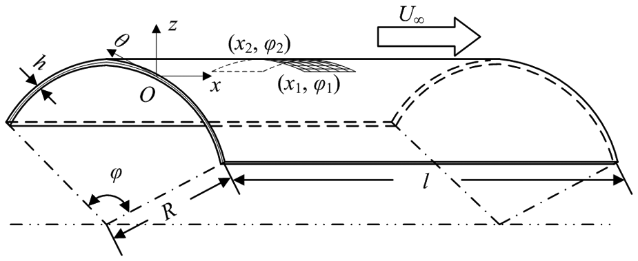
Geometry of a composite laminated open cylindrical shell with piezoelectric patch in subsonic airflow.
Constitutive relations of the structural system
For the composite laminated open cylindrical shell, according to Donnell’s (1976) shell theory, the mid-surface strain
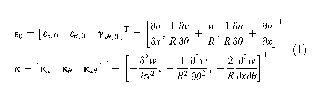
The strain vector in the shell then can be expressed by the function of the displacements

Assume that each layer of the shell is orthotropic, and the ply angle βk of the kth layer is measured from the fiber direction of the kth lamina to the x-direction of the cylindrical coordinate system. The stress–strain relations of the kth layer can be expressed as
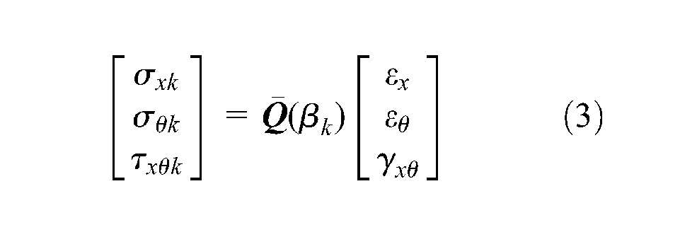
where
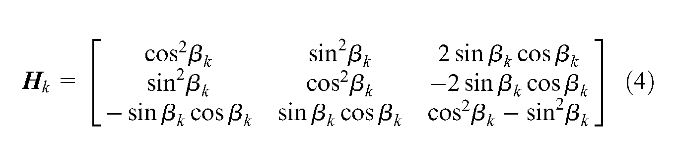
and
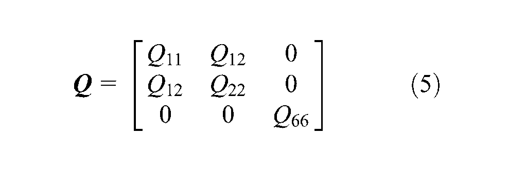
where
The piezoelectric material is transversely isotropic, and the polarization direction is in the z-axis. The constitutive relations of the piezoelectric patch can be expressed as (Kim and Kim, 2005)
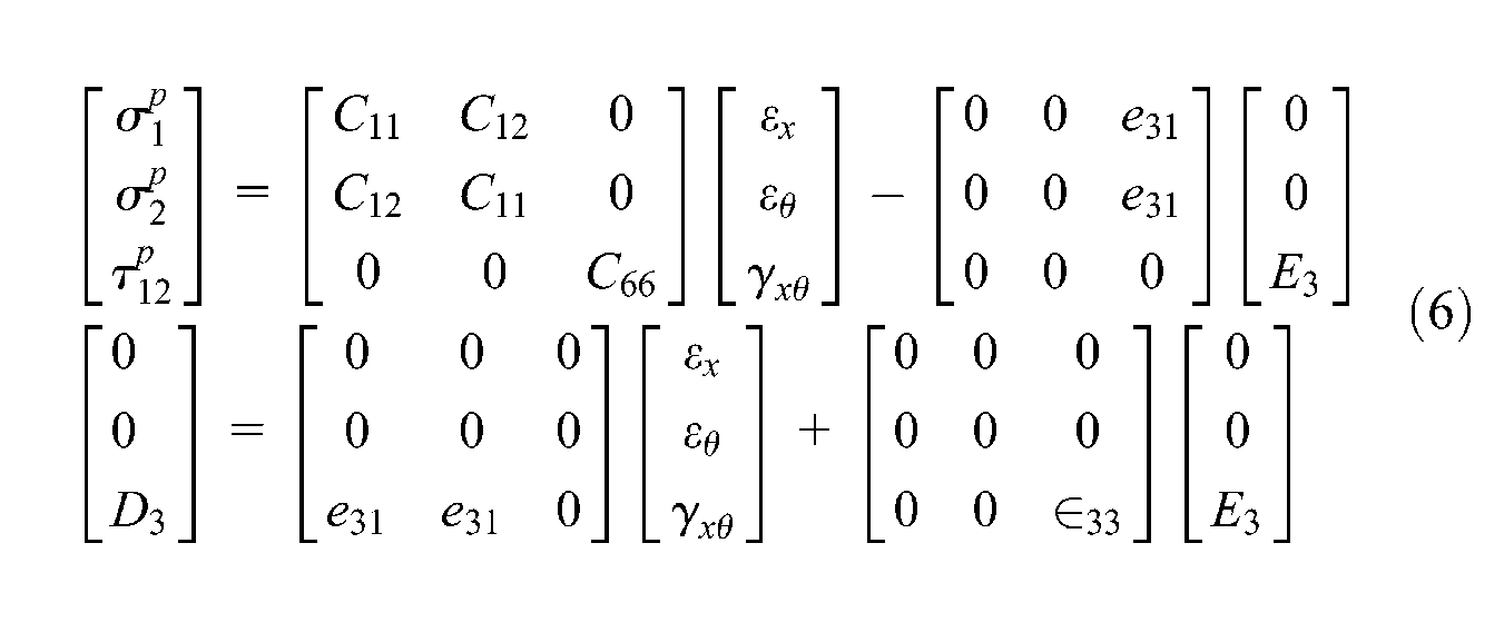
where
The force and moment resultant vectors for the composite laminated open cylindrical shell with symmetric angle ply can be expressed as
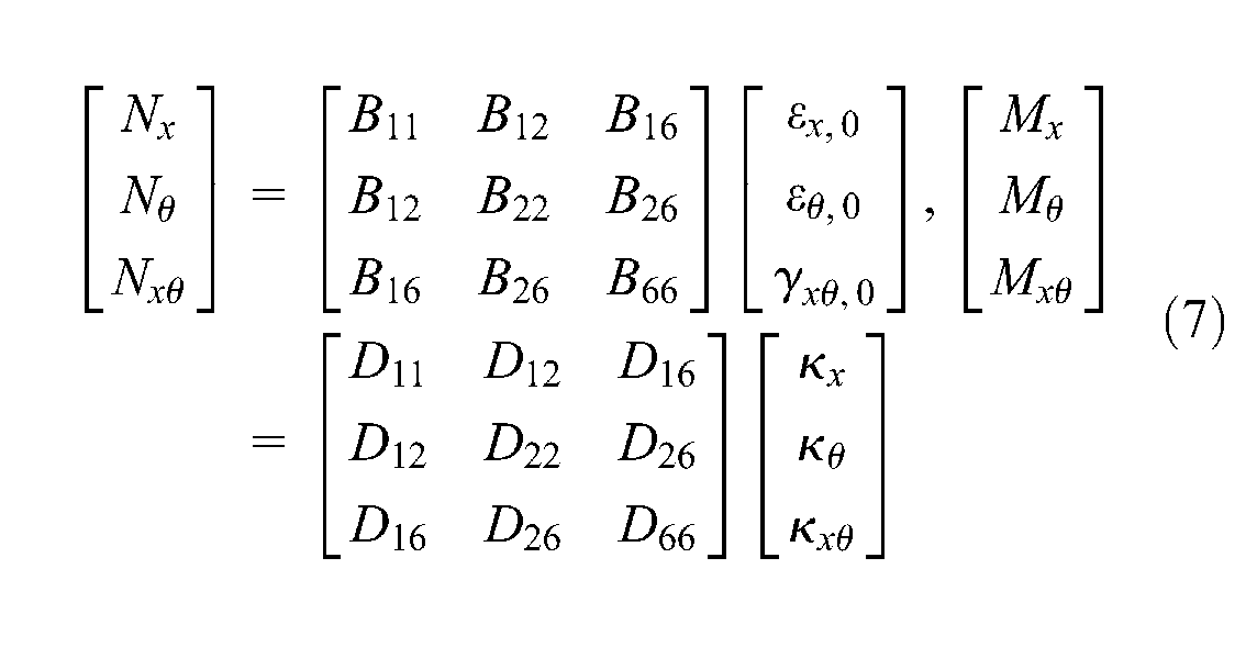
where Bij and Dij are defined as
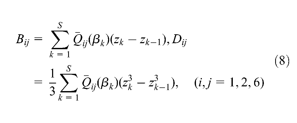
where S is the number of the total layers and zk−1 and zk are the vertical coordinates of the lower and upper surfaces of the kth layer, respectively.
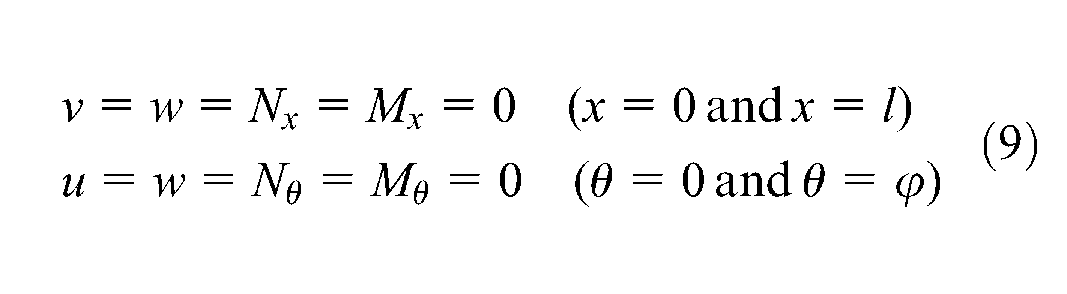
The simply supported boundary conditions at the curved and straight edges can be expressed as
To use Galerkin’s method, the displacements of the shell along the x-, θ-, and z-directions should be expressed in the following forms
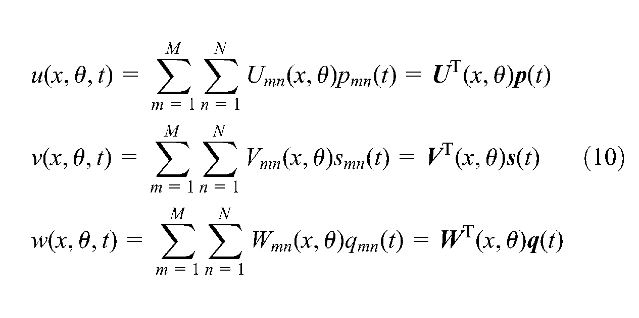
where
The displacement shape functions in equation (10) are expressed as
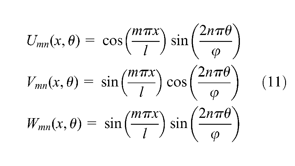
where m is the number of the half waves along the axial direction and n is the number of the circumferential waves. It should be noted that the displacement functions U, V, and W given in equation (11) satisfy the displacement boundary conditions accurately but satisfy the force boundary conditions approximately. However, they are simple in form, and the error is acceptable when the displacements u and v are higher order infinitesimals compared with the radius of the shell.
Aerodynamic model
The linear potential theory is adopted to derive the aerodynamic pressure acting on the external surface of the shell. The subsonic airflow outside the shell is assumed to be incompressible, inviscid, and irrotational to ensure that the potential theory is available.
Introducing the cylindrical coordinate system (x, θ, r) with the origin located at one end of the shell, the potential flow can be described by the Laplace equation (Païdoussis, 2003) as
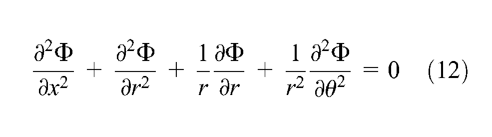
where Φ is the velocity potential.
As the thicknesses of the shell and piezoelectric patch are higher order infinitesimals of the radius R, the effects of the thicknesses on the aerodynamic pressure are neglected. Based on this assumption, the aerodynamic pressure determined by the linear Bernoulli equation is expressed as
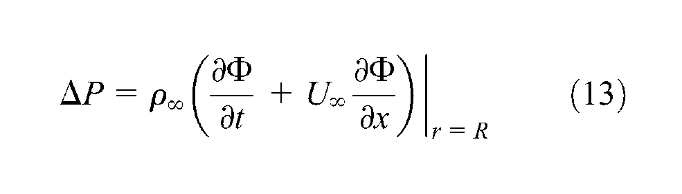
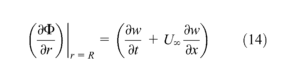
The motion of the fluid and the structure is coupled by the boundary condition
According to the variable separation method, the velocity potential function can be expressed as
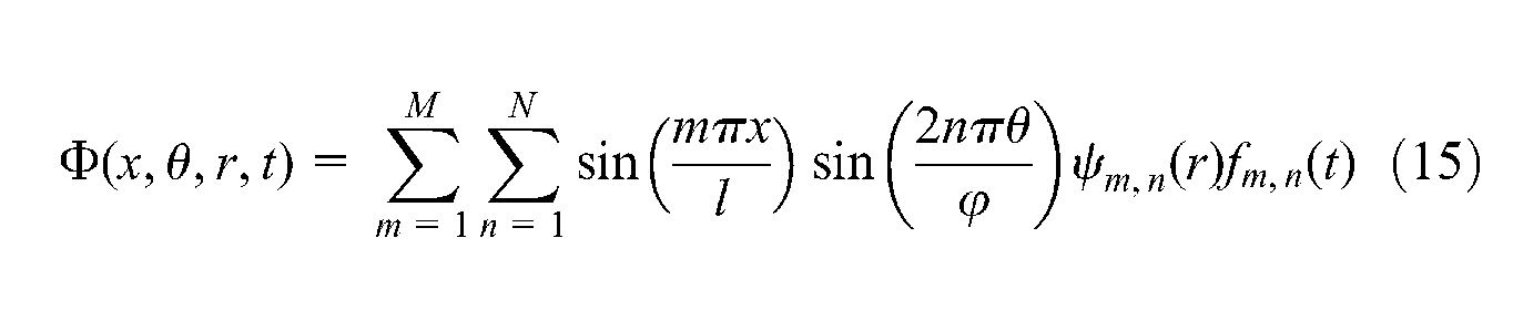
where
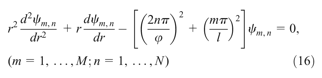
Considering that the pressure is finite outside the shell, the solution of equation (16) can be expressed as
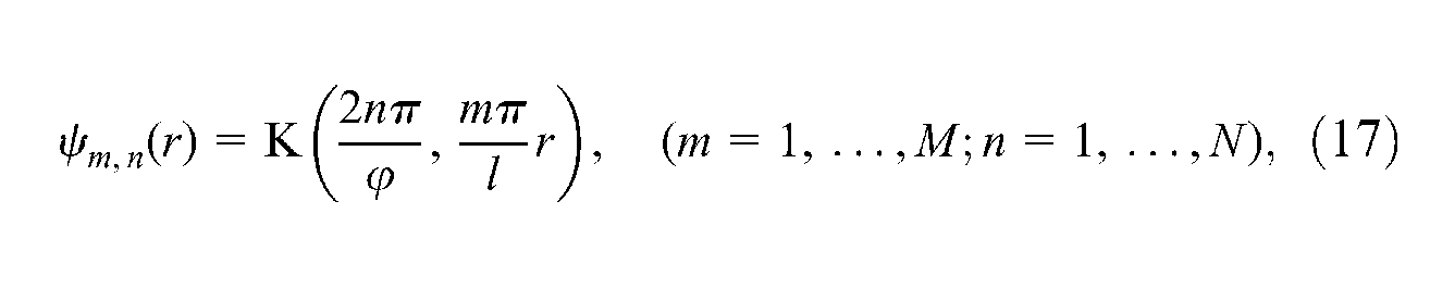
where K is the modified Bessel function of the second kind. Substituting equation (17) into equations (14) and (15), the aerodynamic pressure can be expressed as
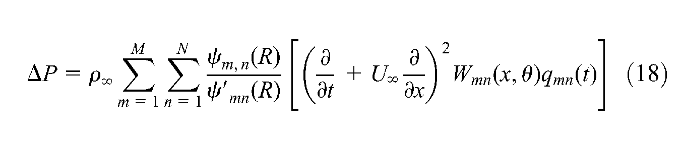
For simplicity, we introduce the following substitutions
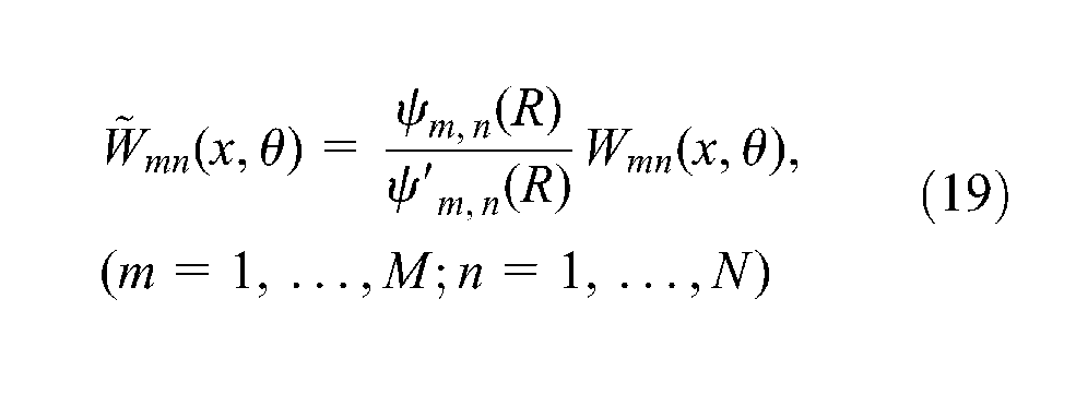
then, the aerodynamic pressure can be expressed as
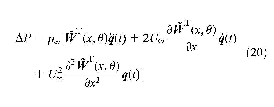
where the vector
Equation of motion of the structural system
The equation of motion of the composite laminated open cylindrical shell with piezoelectric patch in subsonic airflow is derived from Hamilton’s principle
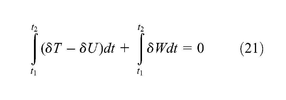
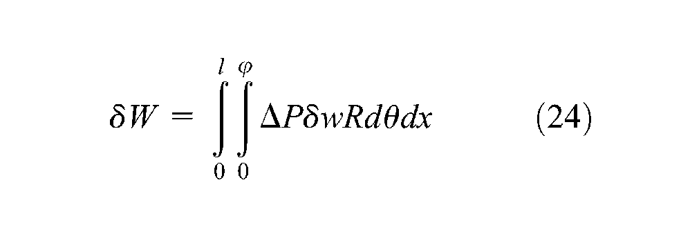
in which U, T, and δW are the potential energy, kinetic energy, and virtual work done by the aerodynamic pressure, and they are expressed as
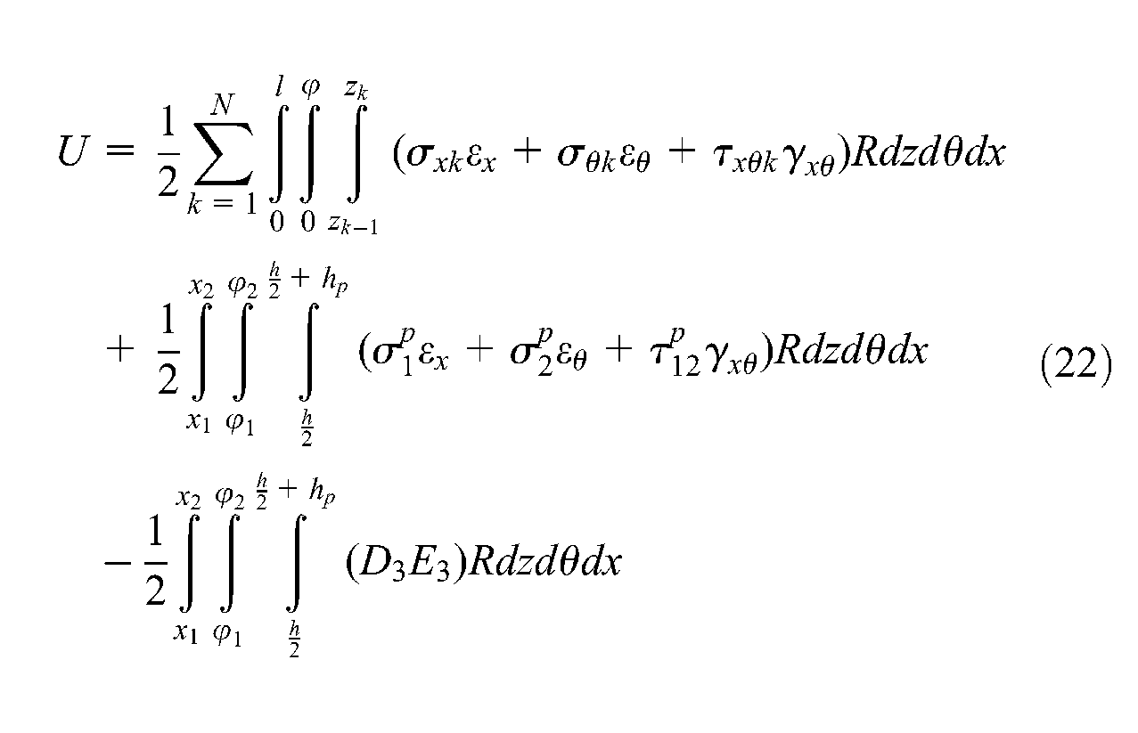
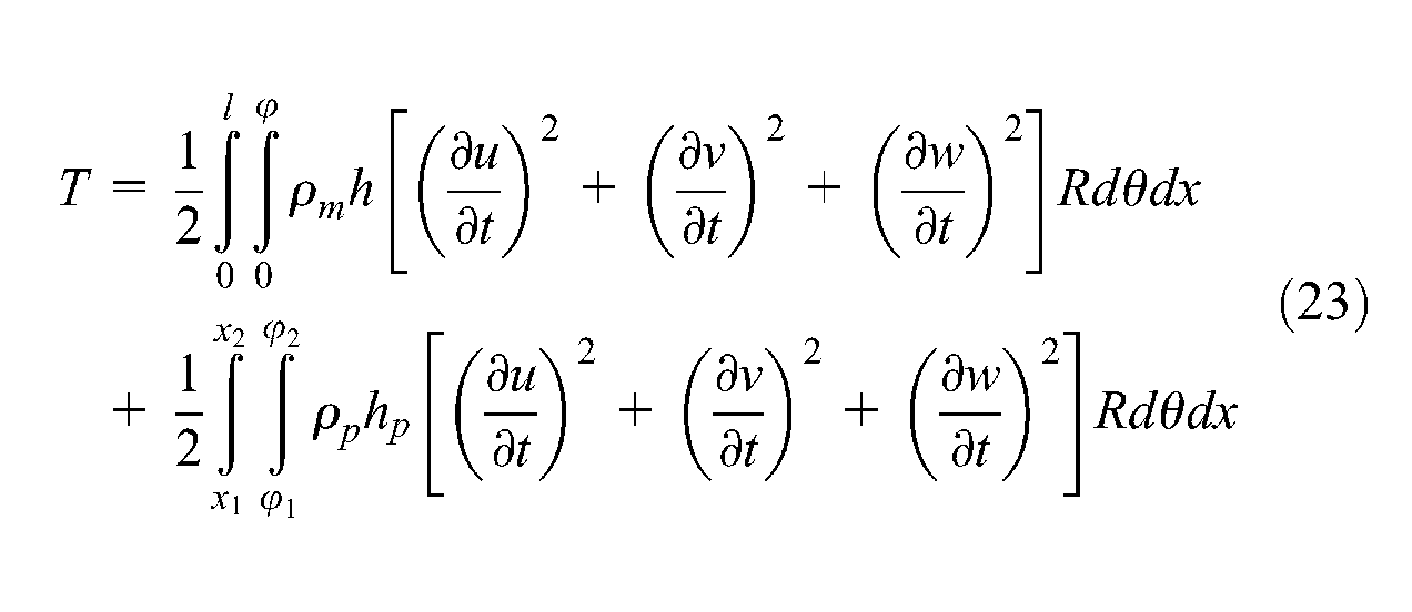
where ρm and ρp are the mass densities of the composite shell and the piezoelectric material, respectively.
Substituting equation (10) into equations (22) to (24), one can obtain the following U, T, and δW expressed by the displacement shape functions and generalized coordinates
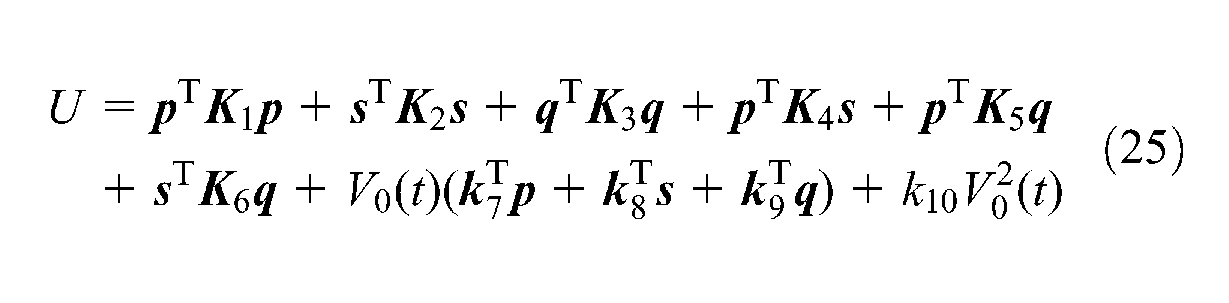
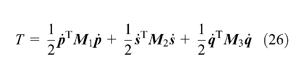
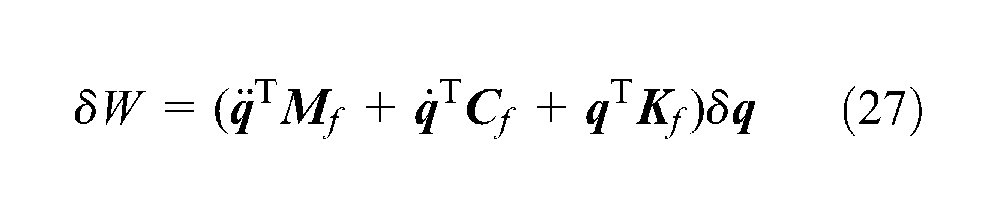
where
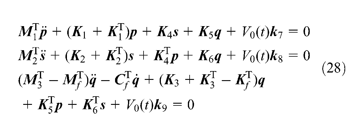
Substituting equations (25) to (27) into equation (21) and performing the variation operation in terms of the generalized coordinates
Introducing
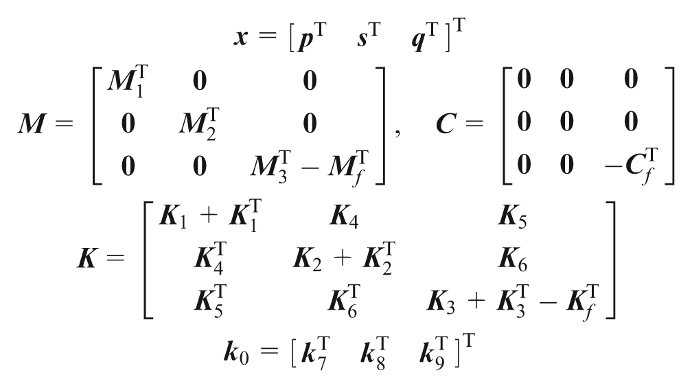
Equation (28) is then transformed into
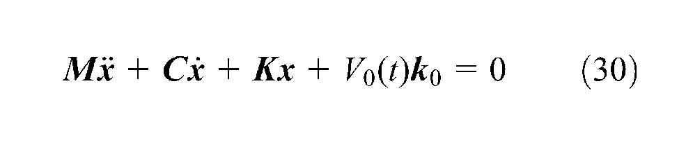
The above equation characterizes the piezoelectric actuator driven under the external applied voltage V0(t). It relates the external applied voltage to the structural deformation. Equation (30) is used to study the active instability control of the composite laminated open cylindrical shell with piezoelectric patch.
Active control strategy
The instability of the open cylindrical shell subjected to the external airflow is characterized by the change of the natural frequencies. With the increase in the flow velocity, all the natural frequencies of the open cylindrical shell decrease. When one of the natural frequencies decreases to zero, the system is unstable (Amabili et al., 1999; Selmane and Lakis, 1997). In order to stabilize the system, the flow velocity for the instability of the system should be reduced. For this purpose, an active control strategy is carried out by exerting appropriate external control voltage to the piezoelectric patch to obtain the active stiffness and mass. The transverse displacement and acceleration measured at the position (x0, θ0) of the open cylindrical shell are fed back to the piezoelectric patch as a control voltage with a control algorithm. The control voltage exerted to the piezoelectric patch has a linear relation to the transverse displacement and acceleration at the position (x0, θ0) of the open cylindrical shell. So the control voltage of the piezoelectric actuator can be expressed as
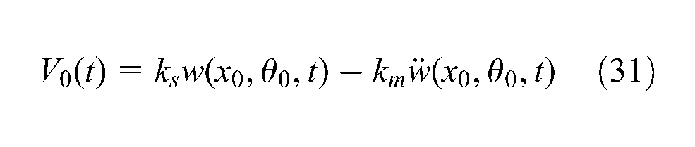
where ks and km are the displacement and acceleration feedback control gains, respectively, for the piezoelectric actuator.
Substituting equation (10) into equation (31), the control voltage can be expressed as
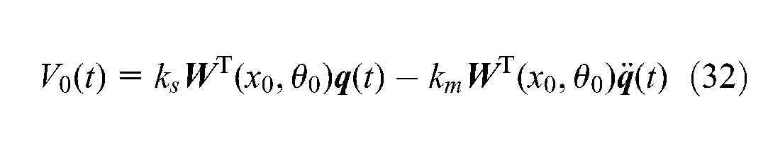
Substituting equation (32) into equation (30), one can obtain the equation of motion with the active mass and stiffness
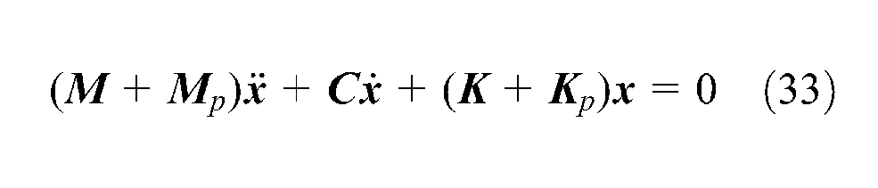
where
The general solution of equation (33) can be expressed as

where
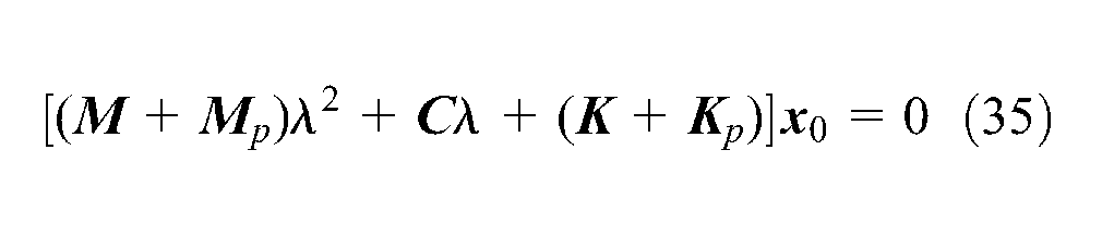
The condition for obtaining a nontrivial solution of equation (35) requires the coefficient determinant to be zero, that is
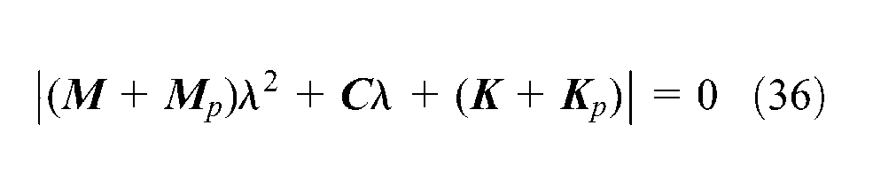
from which the eigenvalues of the structure under different flow velocities can be obtained. The natural frequencies of the structural system then can be expressed by the imaginary parts of λ.
Numerical simulations and discussions
A composite laminated open cylindrical shell with symmetric angle ply composed of three layers with the same thickness is studied. The structural and material properties are as follows: l = 2 m, R = 1 m, h = 0.001 m, the opening angle ϕ = 120° or 180°, ρm = 1600 kg/m3, E1 = 5 × 10⁹ N/m2, E2 = 1 × 10⁹ N/m2, G12 = 1 × 10⁹ N/m2, ν12 = 0.05, and ν21 = 0.25. The ply angle of the composite laminated plate is [β/−β/β], where β changes from 15° to 75°. The piezoelectric patch is bonded at the outer surface of the open cylindrical shell. Its material and structural properties are as follows: elastic constants C11 = 1.39 × 10¹¹ N/m2, C12 = 0.778 × 10¹¹ N/m2, and C66 = 0.306 × 10¹¹ N/m2; mass density ρp = 7500 kg/m3; and piezoelectric constant e31 = −6.98 C/m2. The location of the piezoelectric patch is determined by
Validity of the present method
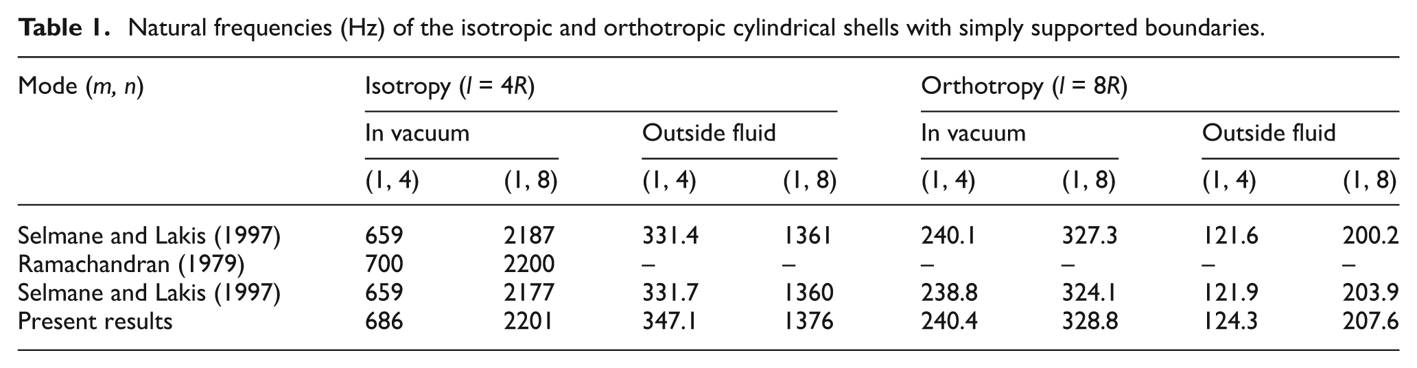
In order to verify the correctness of the fluid and structure models used in this study, the natural frequencies obtained from the present method are compared with the results in open literatures for both isotropic and orthotropic cylindrical shells with and without coupling with the external fluid.
The structural and material properties are as follows: R = 0.235 m, h = 0.000235 m, ρm = 7850 kg/m3, and ϕ = 360° for both isotropic and orthotropic cylindrical shells. For the isotropic one, the elastic modulus E = 21.981 × 10¹¹ N/m2 and Poisson’s ratio ν = 0.3. For the orthotropic one, the elastic moduli are Ex = 1.0 × 10¹¹ N/m2, Eθ = 0.5 × 10¹¹ N/m2, and Gxθ = 0.1 × 10¹¹ N/m2, and Poisson’s ratios are νx = 0.05 and νθ = 0.025. The density of the static external flow is 1000 kg/m3.
Table 1 shows the natural frequencies of the isotropic and orthotropic cylindrical shells with and without coupling with the external fluid for different modes. From Table 1, it can be seen that the present results are in good agreement with the reported ones, which proves the validity of the present method.
Natural frequencies (Hz) of the isotropic and orthotropic cylindrical shells with simply supported boundaries.
Stability analysis
In this section, the instability velocities of the composite open cylindrical shell without piezoelectric patch are studied. The effects of the ply angle and opening angle of the shell on the instability velocity are discussed. In order to obtain the instability velocities, the variations in the natural frequencies of the open cylindrical shell with the flow velocity are calculated for different ply angles.
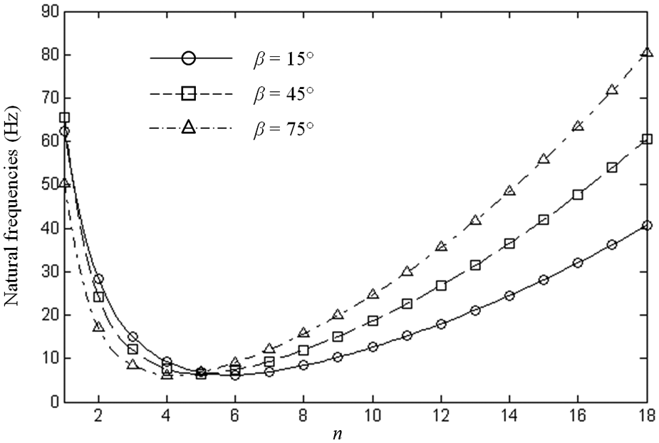
Normally, with the increase in the flow velocity, lower order natural frequencies fall to zero faster. So in the simulation, only the first three natural frequencies are considered. Figure 2 shows the natural frequencies of the composite open cylindrical shell with different ply angles when ϕ =120° and U∞ = 0. From Figure 2, the fundamental mode and the other two modes closest to the fundamental mode can be identified. These preliminary works are done to make the subsequent stability analysis convenient.
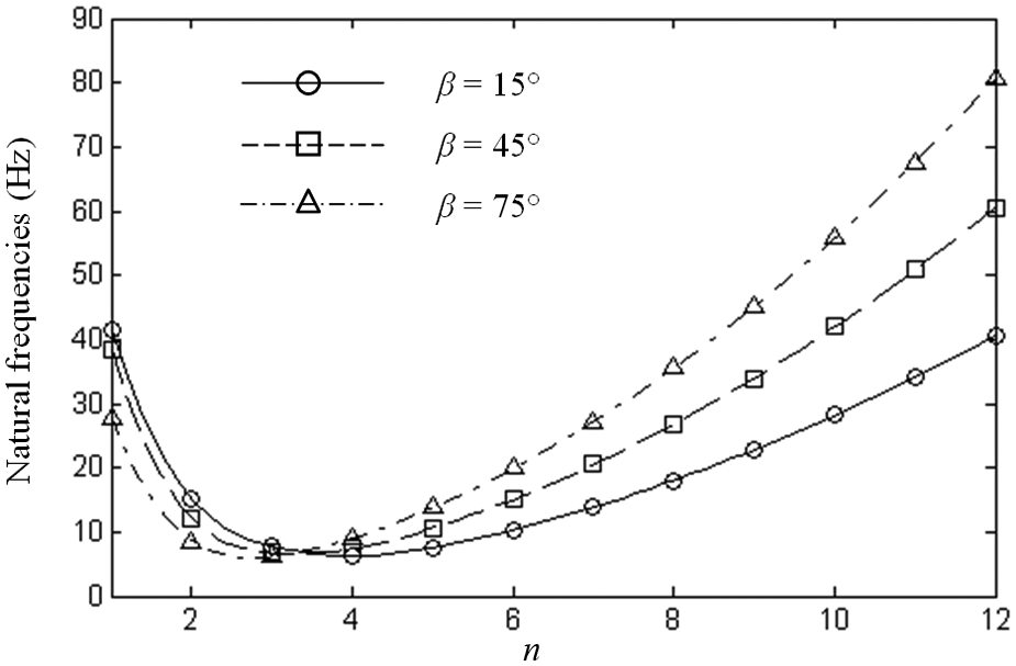
Natural frequencies of the composite open cylindrical shell when ϕ = 120° for different ply angles (m = 1).
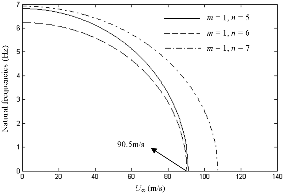
From Figure 2, we know that the first three natural frequencies of the composite open cylindrical shell corresponding to β = 15° can be obtained when m = 1 and n = 3, 4, 5. Figure 3 shows the variations in the first three natural frequencies of the open cylindrical shell with the flow velocity. It can be seen in Figure 3 that with the increase in the flow velocity from zero, all the natural frequencies decrease. When U∞ increases to about 90.5 m/s, the natural frequency associated with mode (1, 4) vanishes, indicating that the structural system is in the instability state of the divergence type and the instability velocity U∞ = 90.5 m/s.
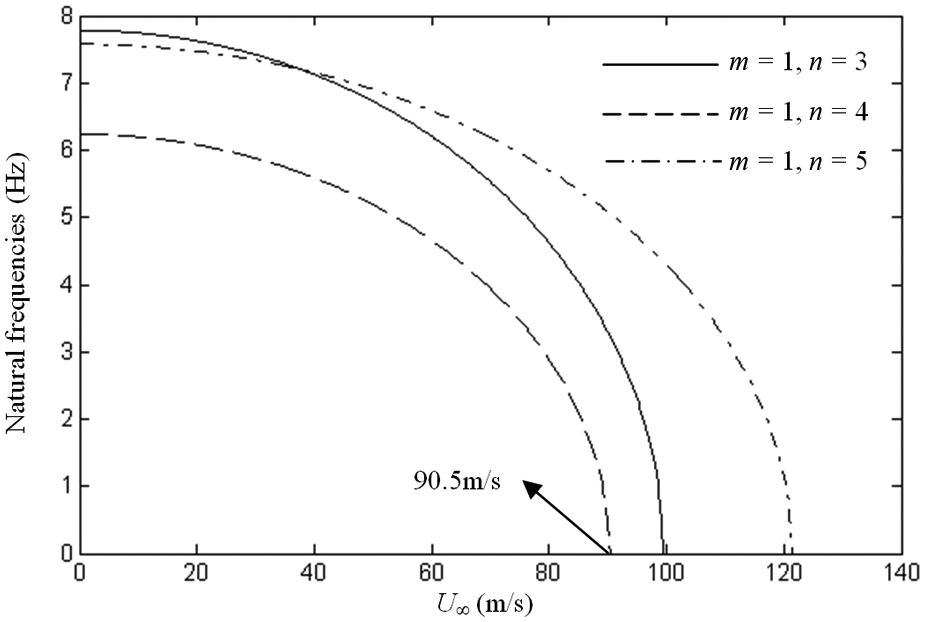
Variation in the first three natural frequencies of the composite open cylindrical shell when ϕ = 120° and β = 15° with the flow velocity.
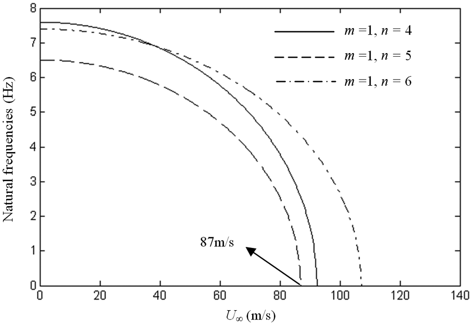
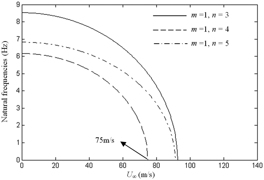
Similarly, as shown in Figure 4, the instability velocity of the composite open cylindrical shell corresponding to β = 45° can be obtained for the mode (1, 3) when U∞ = 86.25 m/s. Figure 5 shows the instability velocity U∞ = 79.5 m/s for the mode (1, 3) when the ply angle β = 75°.
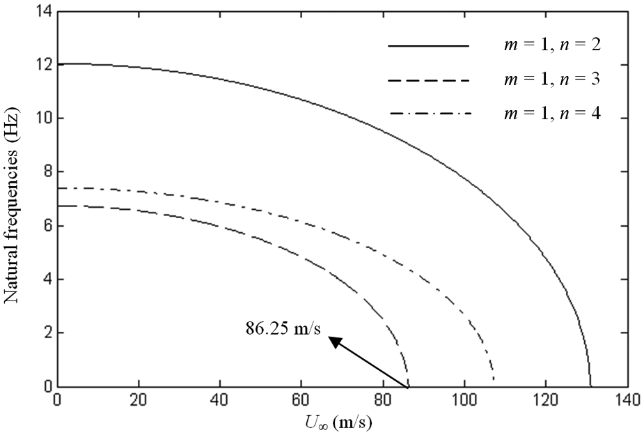
Variation in the first three natural frequencies of the composite open cylindrical shell when ϕ = 120° and β = 45° with the flow velocity.
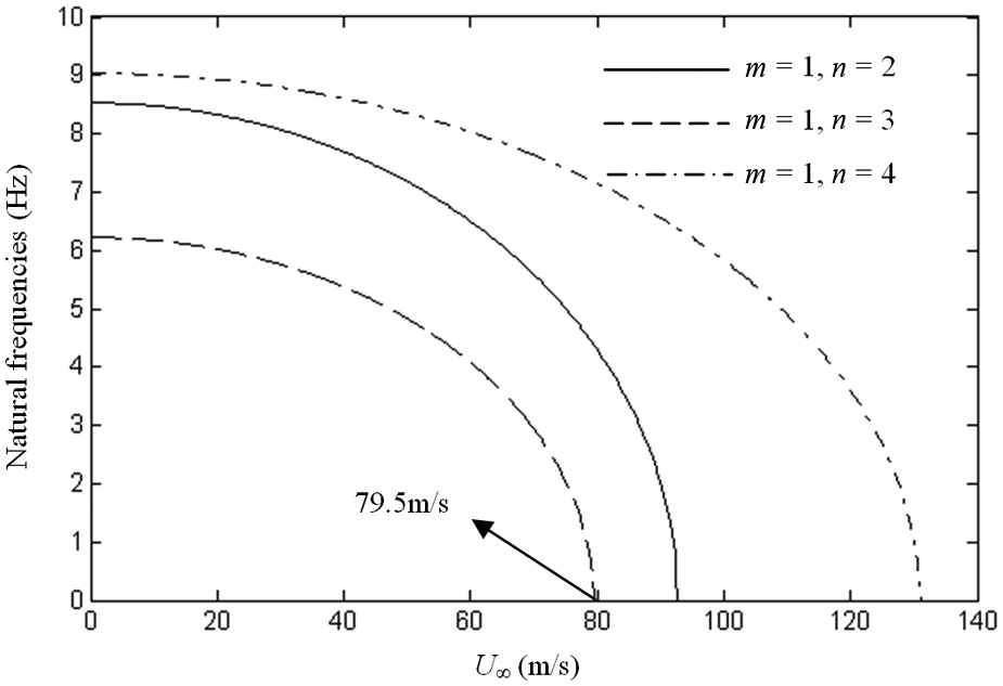
Variation in the first three natural frequencies of the composite open cylindrical shell when ϕ = 120° and β = 75° with the flow velocity.
From Figures 3 to 5, we can conclude that with increase in the flow velocity, all the natural frequencies decrease, which illustrates that the effect of the external subsonic airflow on the structural system resembles the in-plane load leading to the divergence of the shell. It can also be seen that with increase in the ply angle, the instability velocity decreases, which implies that the composite open cylindrical shell with smaller ply angles exhibits better aerodynamic properties than that with larger ones.
For the opening angle ϕ = 180°, the similar procedures are carried out to obtain the instability velocities as well as the corresponding modes of the structural system for different ply angles. A series of results are shown in Figures 6 to 9. It can be seen that the instability velocity U∞ = 90.5 m/s at mode (1, 6) when the ply angle β = 15°, the instability velocity U∞ = 87 m/s at mode (1, 5) when the ply angle β = 45°, and the instability velocity U∞ = 75 m/s at mode (1, 4) when the ply angle β = 75°.
Natural frequencies of the composite open cylindrical shell when ϕ = 180° for different ply angles (m = 1).
Variation in the first three natural frequencies of the composite open cylindrical shell when ϕ = 180° and β = 15° with the flow velocity.
Variation in the first three natural frequencies of the composite open cylindrical shell when ϕ = 180° and β = 45° with the flow velocity.
Variation in the first three natural frequencies of the composite open cylindrical shell when ϕ = 180° and β = 75° with the flow velocity.
It can also be seen that for the same ply angles, the difference between the instability velocities of the open cylindrical shell is not significant for β = 15° and 45°. When β = 75°, the instability velocity of the open cylindrical shell with opening angle ϕ = 180° is smaller than that with ϕ = 120°.
Active control of instability
In this section, the active instability control of the composite open cylindrical shell coupling with the external airflow is studied. Without loss of generality, we choose the opening angle ϕ = 120° and the ply angle β = 45° in the simulation.
Figure 10 shows the effects of the displacement and acceleration feedback control strategies on the instability of the composite open cylindrical shell. Because the instability velocity of the structural system is determined by the frequency curve decreasing to zero, only the frequency curve that approaches zero first is considered here. In the simulation, the control gains ks and km are set to be zero first, which corresponds to the uncontrolled system. In this case, the instability velocity is determined by the frequency curve of mode (1, 3). We can see from Figure 10 that with the increase in the flow velocity, the natural frequency corresponding to mode (1, 3) decreases to 0 when U∞ = 91 m/s. Then, we set ks = 2 × 10⁵ and km = 0, which indicates that only the displacement feedback control is carried out. It can be seen that compared with the uncontrolled system, the instability velocity moves toward right, which indicates that the stability properties of the open cylindrical shell is improved. For another case, we set ks = 0 and km = 23, that is, only the acceleration feedback control is carried out. It can be seen in Figure 10 that despite the natural frequency corresponding to mode (1, 3) increases before the instability of the structural system, the instability velocity remains unchanged. This phenomenon illustrates that the instability velocity of the system is independent of the added active mass matrix
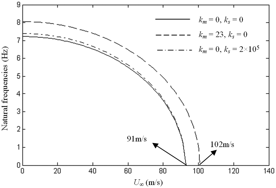
Comparison of the static instability velocities of the composite open shell with piezoelectric patch when ϕ = 120° and β = 45° for different control gains (m = 1, n = 3).
Figure 11 shows the effects of the displacement feedback control gain on the instability velocity of the system. From Figure 11, it can be seen that with increase in the displacement feedback control gain, the instability velocity increases.
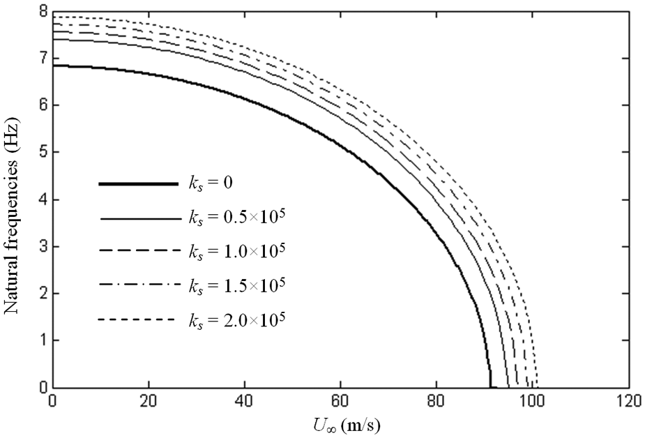
Comparison of the static instability velocities of the composite open shell with piezoelectric patch when ϕ = 120° and β = 45° for different control gains (km = 0, m = 1, n = 3).
Figure 12 shows the displacement–time histories of the shell with and without active control. The initial conditions are chosen as
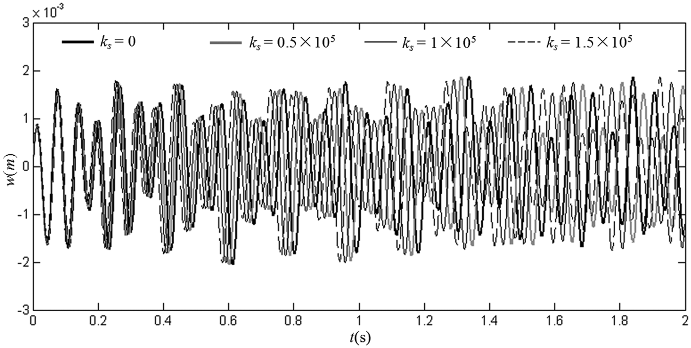
Comparison of the displacement–time histories at (x0, θ0) of the shell when U∞ = 85 m/s, ϕ = 120°, and β = 45° for different control gains (km = 0).
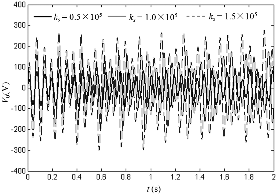
Comparison of the actuator input voltages when U∞ = 85 m/s, ϕ = 120°, and β = 45° for different control gains (km = 0).
Conclusion
In this article, the stability analysis and active control of a composite laminated open cylindrical shell with simple supports in subsonic airflow are conducted. Based on Donnell’s shell theory, the equation of motion of the structural system is established by using Hamilton’s principle and transformed into ordinary differential equations (ODEs) by using Galerkin’s method. The displacement and acceleration feedback control strategies are used to control the instability of the structural system. The flow velocity as well as the corresponding mode for the open cylindrical shell under instability is obtained by solving the generalized eigenvalue problems of the system. The effects of the ply angles of the shell and the feedback control gains on the stability of the structural system are discussed. From the results, the following conclusions can be drawn.
With increase in the flow velocity, all the natural frequencies decrease. When one of the natural frequencies falls to zero, the system will be under instability of the divergence type.
For the given opening angles, the composite laminated open cylindrical shell with smaller ply angles exhibits better aerodynamic characteristics than that with larger ones.
The difference between the instability velocities of the open cylindrical shell with different opening angles is not significant for smaller ply angles.
The displacement feedback control can improve the stability characteristics of the system. With increase in the displacement feedback control gain, the instability velocity of the system increases, and accordingly, more stable system needs higher input voltage to sustain.
The acceleration feedback control can increase the natural frequencies of the structural system before instability. However, the instability velocity of the open cylindrical shell under acceleration feedback control remains unchanged, which implies that the added active mass does not affect the instability velocity.
This study can be helpful for the stability analysis and aerodynamic design of the composite laminated open cylindrical shells in subsonic airflow.
Footnotes
Appendix 1
Appendix 2
Funding
This research is supported by the National Basic Research Program of China (no. 2011CB711100) and the National Natural Science Foundation of China (nos 11172084 and 10672017).