
Abstract
This article examines the piezoelectric-based energy harvesting on civil infrastructures. Piezoelectric cantilever–based harvesters are adopted considering their wide usage. Four concrete slab-on-girder bridges that represent the majority of bridges in the United States are used as the platforms for the energy harvesting. In the simulation, the distributed-parameter model is used for the energy harvester, while four three-dimensional bridges with HS20-44 truck models are developed using ANSYS and MATLAB. Two scenarios for the bridge–vehicle systems are simulated: bridges with only one passing vehicle and bridges with a continuous vehicle flow. A parametric study is carried out to study the effect of various properties of the bridge and vehicle on energy harvesting. The simulation result shows that the energy output power increases with poorer road conditions and smaller bridge span lengths. Optimal vehicle speeds and energy harvester positions are also investigated and discussed in this article.
Introduction
Bridges are crucial parts in a ground transportation system. Their failures can cause tremendous economic and life loss. However, 24% of the 605,086 bridges in the United States are estimated as either structurally deficient or functionally obsolete based on the 2011 data from the Federal Highway Administration (FHWA, 2011). To reduce the risk of the deficient bridges, structural health monitoring systems have been developed and widely used in the last decade that provide surveillance, evaluation, and assessment for existing or newly built bridges (Ko and Ni, 2005; Lynch and Loh, 2006). As an advancement of structural health monitoring, wireless sensor network has gained considerable attention recently. It has many advantages over traditional wired systems, including lower cost, easier installation and maintenance, and better ability to be applied to existing bridge infrastructures (Sazonov et al., 2004). However, the power supply for the wireless sensor network limits its applications and development. As a sustainable power source, energy harvesting provides a promising way to supply power for the wireless sensor networks, while its applications on bridge system have been seldom studied. To predict and optimize the performance of energy harvesting on bridge systems, piezoelectric-based energy harvesting is studied for various bridges under different conditions in this article.
For harvesting energy from bridge vibrations, there are mainly three different kinds of mechanisms: electromagnetic, piezoelectric, and electrostatic. Among the three, the piezoelectric-based energy harvesting is a very mature one, which has been widely used and intensively studied (Kompis and Aliwell, 2008). Most of the piezoelectric energy harvesters have the form of a cantilever beam that gives the harvester the advantages of high energy density, simple mechanism, and good reliability. In this article, the study of energy harvesting is focused on the piezoelectric cantilever–based energy harvester.
There has been some reported research on the energy harvesting in civil infrastructures in the last decade. Park et al. (2008) reviewed the development of energy harvesting for low-power embedded structural health monitoring sensing systems. Sazonov et al. (2009) presented a novel wireless sensor system powered by electromechanical energy harvesters that are excited by the vibrations of a bridge under passing traffic loading. Galchev et al. (2011) proposed an electromechanical energy harvester, which can be operated under vibrations with a wide acceleration and frequency range. Its performance was tested along the length of a suspension bridge. Green et al. (2013) studied the performance of nonlinear harvesters under various excitations including the bridge vibrations. Particularly for the piezoelectric energy harvesting, there are also a few studies on its applications in civil infrastructures. Elvin et al. (2006) studied the feasibility of energy harvesting for powering a structural health monitoring system. Piezoelectric cantilever–based harvesters were used for the simulation, and their energy outputs in different bridge and building structures were obtained under various loading conditions. Kim et al. (2011) experimentally examined the piezoelectric effect on various loading conditions for the possibility of harvesting energy from bridges. Piezoelectric patches were attached on a steel beam-slab type bridge specimen and were tested under various structural responses corresponding to various traffic conditions. The experimental results were compared with the numerical simulation results and indicated that the energy outputs were largely affected by the strain increasing rate and peak strain in the piezoelectric patches. Erturk (2011) formulated the problem of piezoelectric energy harvesting on a bridge system that includes the energy harvesting from bridge vibrations excited by moving loads and from the bridge surface strain fluctuations. Both the piezoelectric cantilever and the piezoelectric patch were modeled, and a case study was also given for the attached piezoelectric patch on a bridge. Ali et al. (2011) studied the energy output from piezoelectric energy harvesting in highway bridges. A two-dimensional (2D) bridge model with a moving point load was investigated, and a linear single-degree-of-freedom model was used for the piezoelectric energy harvester.
In the aforementioned studies, simplified bridge models or harvester models were used for the piezoelectric energy harvesting simulation. These simplifications facilitate the calculation of energy output from the harvesters but may lead to impractical or misleading conclusions. Besides, the piezoelectric cantilever, as the most widely used harvester formation, has not been comprehensively studied regarding its performance on bridge systems that typically have low vibration frequencies. The aims of this article are to provide a method that can accurately model the harvester–bridge system and to provide guidance for the design and operation of the piezoelectric-based energy harvester on bridge systems by studying its performance under various bridge conditions and loading conditions.
Bridge–vehicle system modeling
Bridge model
More than 40% of the bridges in the United States are stringer/multi-girder bridges, and 57.9% of them have a simple structure formation of the so-called slab-on-girder bridge (FHWA, 2011). To represent the majority of the slab-on-girder bridges in the United States, four typical pre-stressed concrete girder bridges with span lengths ranging from 16.76 m (55 ft) to 39.62 m (130 ft) are used for energy harvesting simulation in this article (Deng and Cai, 2010). All four bridges are designed according to the American Association of State Highway and Transportation Officials (AASHTO) standard specifications, and each bridge consists of five identical girders with a girder spacing of 2.13 m (7 ft) that are simply supported. The roadway width and bridge deck thickness for the bridges are 9.75 m (32 ft) and 0.20 m (8 in), respectively. The energy harvesters are located at the positions of 1/4, 1/2, and 3/4 span length on each girder as shown in Figure 1. To obtain the bridge properties such as natural frequencies and vibration modes, the four bridges are modeled using solid elements in the ANSYS program. Detailed properties of the four bridges are shown in Table 1 (Deng and Cai, 2010).
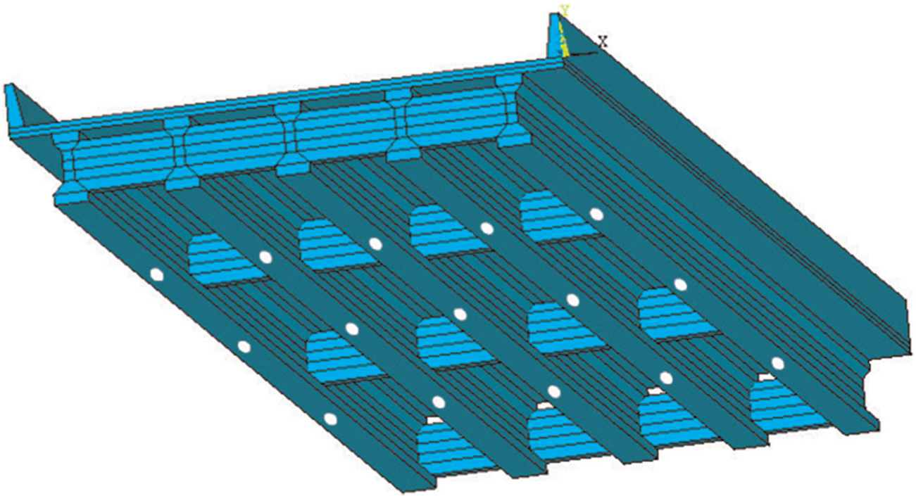
Model of bridge and harvester positions.
Parameters of the bridge models.
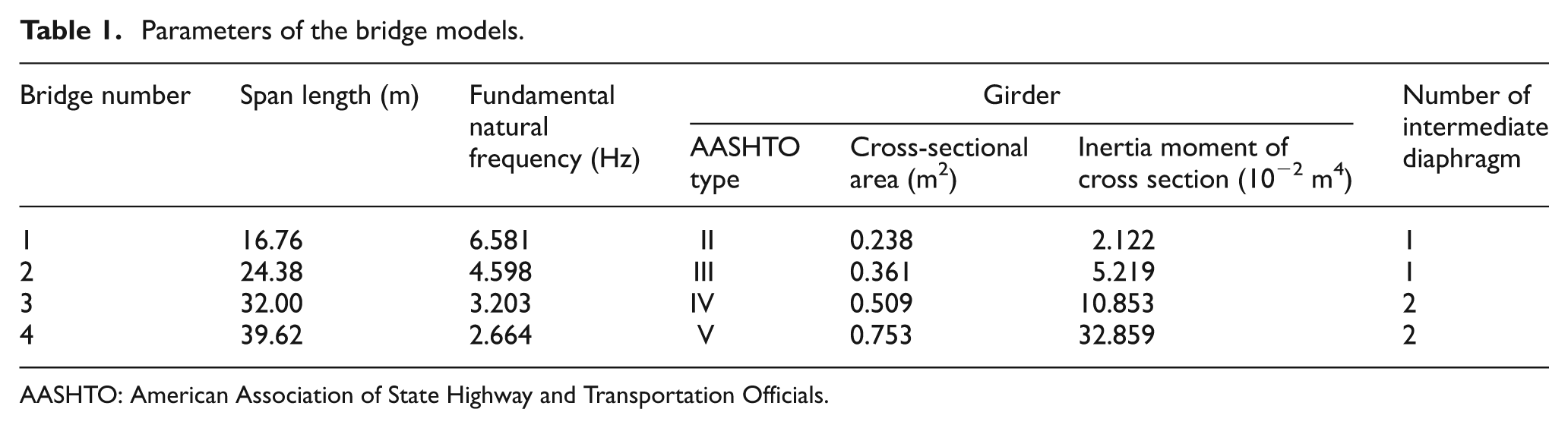
AASHTO: American Association of State Highway and Transportation Officials.
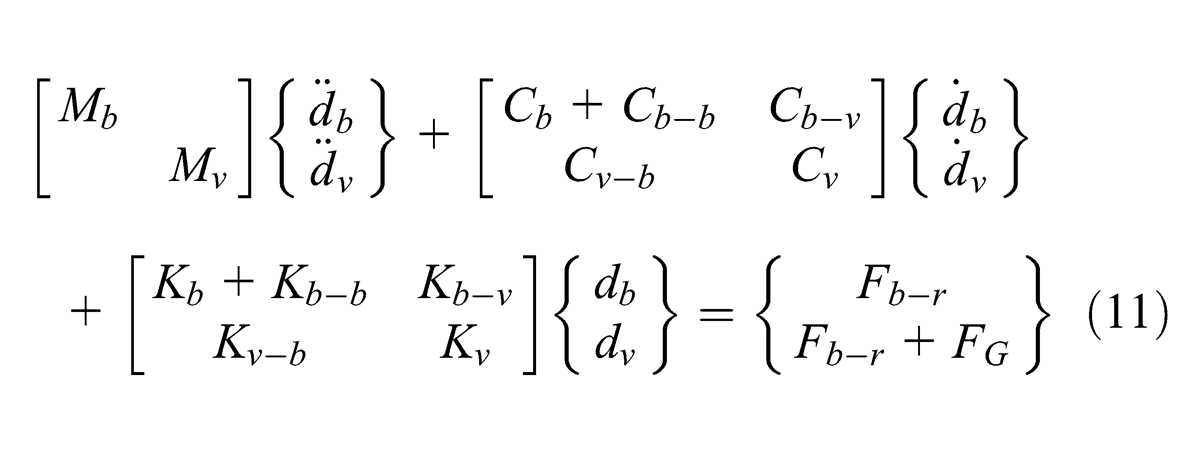
The equation of motion for a bridge can be written as
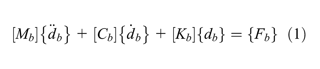
where
With the modal superposition technique, the displacement vector of the bridge
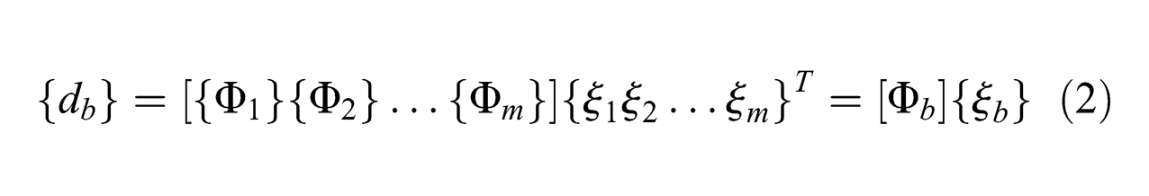
where m is the total number of the modes used for the bridge under consideration and
Each mode shape is normalized, and the damping matrix
Vehicle model
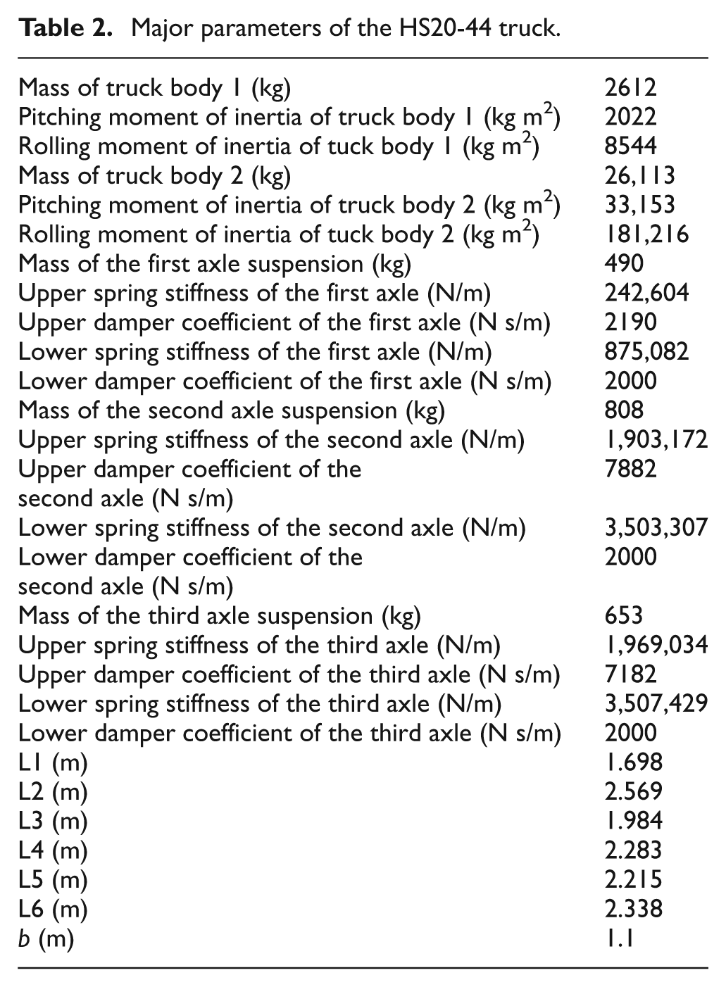
The vibration of a bridge is usually excited by the passing-by vehicles, wind, and even earthquakes in some extreme and unexpected events. Since the energy harvesting studied in this article is aimed at daily operation and the vibration caused by wind is very small on the slab-on-girder bridges, only vehicle loadings are considered in this study. According to the AASHTO bridge design specifications, a major design vehicle AASHTO HS20-44 truck is used as the vehicle loading for the four bridges. The analytical model for this truck is illustrated in Figure 2 (Shi, 2006), and its properties are shown in Table 2 (Shi, 2006).
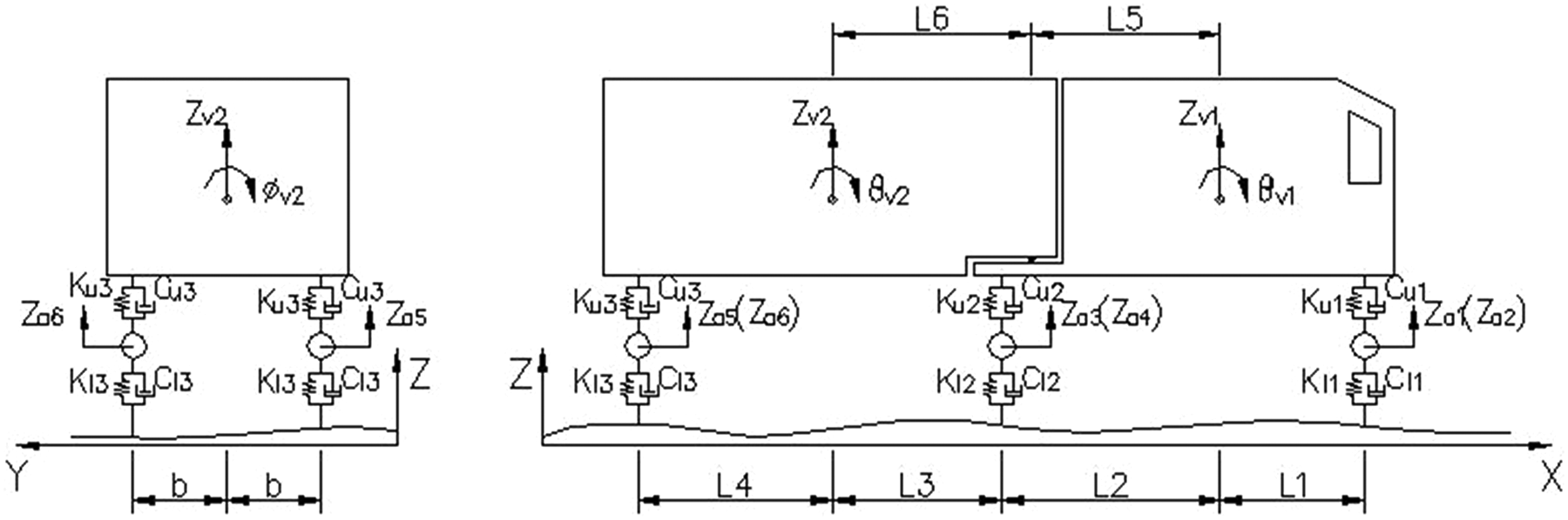
Analytical model of the HS20-44 truck.
Major parameters of the HS20-44 truck.
The equation of motion for the vehicle on a ground can be expressed as
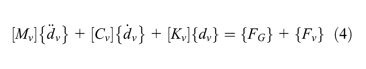
where
Vehicle–bridge coupled system
To assemble the vehicle and bridge model into a coupled system, the vehicle wheels are assumed to be in contact with the bridge all the time. At any contact point, the relationship among the vertical displacement of vehicle body
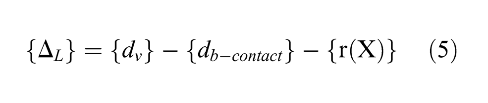
For the road surface profile
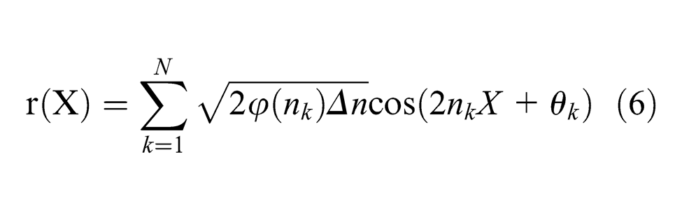
where
In this study, the following PSD function (Huang and Wang, 1992) was used
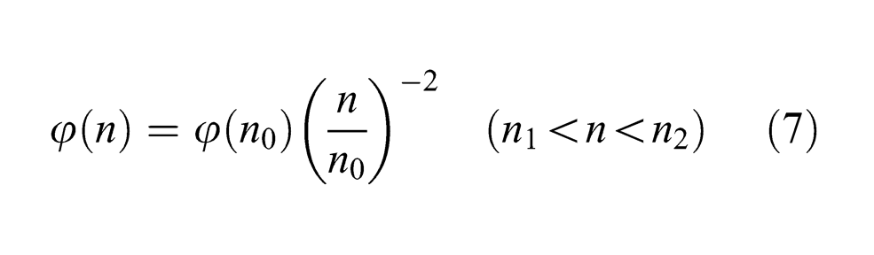
where n is the spatial frequency (cycle/m),
The International Organization for Standardization (ISO 8608:1995, 1995) has classified the road roughness as types A (very good) to H (very poor).The road conditions: very good, good, average, poor and very poor are used in the present study. The values of
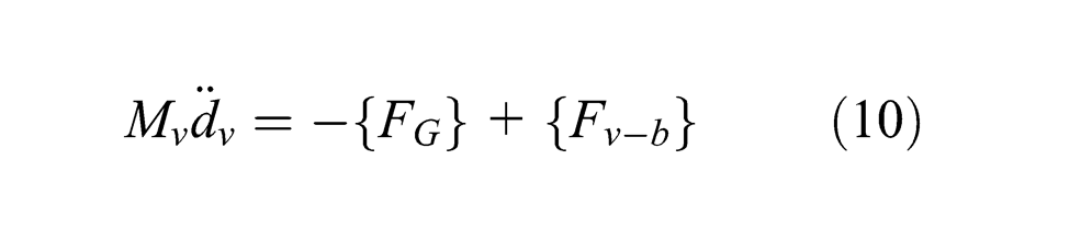
At the contact point, the interaction forces acting on the bridge

For the vehicle model, the reaction forces are expressed as follow

and equation (4) can be rewritten as
For the bridge model, the interaction forces acting on the bridge
With the displacement relationship (equation (5)) and the interaction force relationship (equation (9)) at the contact point, the vehicle–bridge coupled system can be formulated by combining the equations of motion of both the bridge and vehicle as shown below
where
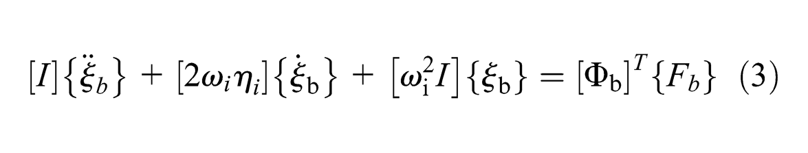
Using equation (3), equation (4) can be rewritten as
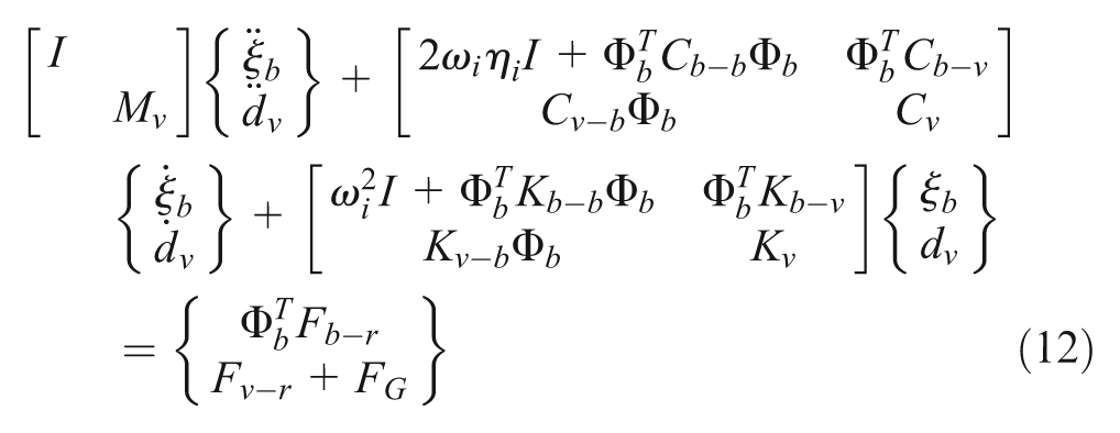
A MATLAB program named BIRDS-BVI (laboratory of Bridge Innovative Research and Dynamics of Structures-Bridge Vehicle Interaction) is developed to establish the vehicle–bridge coupled system in equation (12) and is used to solve the equations by the fourth-order Runge–Kutta method in the time domain. The modal information of the bridge is obtained using the finite element program ANSYS and then imported into the MATLAB before assembling the equations.
Piezoelectric cantilever beam harvester model
For piezoelectric energy harvesting, a composite cantilever beam is the most common way for collecting vibration energy from its host structure. By attaching one or two piezoelectric patches on a cantilever beam, the dynamic bending strain induced by the vibration of the beam can generate electric potential difference in the piezoelectric patch, which can be obtained as electric energy. Typically, the fundamental natural frequency of the cantilever beam is tuned to the fundamental natural frequency of the host structure. Considering the low fundamental natural frequency of bridge structures, a cantilever with a single piezoelectric layer is used for the energy harvester in this study that reduces the stiffness of the whole composite beam and therefore lowers the fundamental natural frequency of the harvester. The positions of the harvesters are shown in Figure 1.
For the modeling of a piezoelectric cantilever–based harvester, several different models have been proposed (Erturk, 2009; Lu et al., 2004; Sodano and Inman, 2004). Among the proposed models, the distributed-parameter model (Erturk, 2009) is a recently developed model with a full consideration of the electromechanical coupling effect for the piezoelectric dynamic system. This model is therefore used in this study.
As shown in Figure 3, the harvester consists of a composite cantilever beam made of a piezoelectric layer and substructure, a proof mass on the tip of the cantilever beam, and an external circuit with a changeable resistance. The x-y coordinate system and the polling direction of the piezoelectric layer are also shown in Figure 3 and will be used in all the subsequent sections. The vibration and voltage output for the harvester are described by equations (13) and (14) in the following
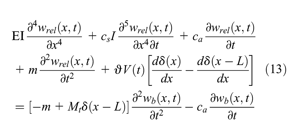
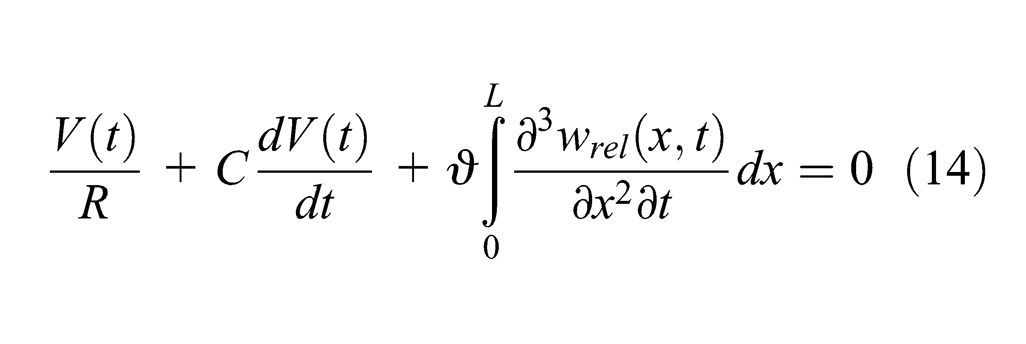
where
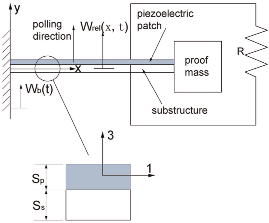
Piezoelectric cantilever beam model.
For the piezoelectric cantilever beam as shown in Figure 3, its bending stiffness can be formulated as
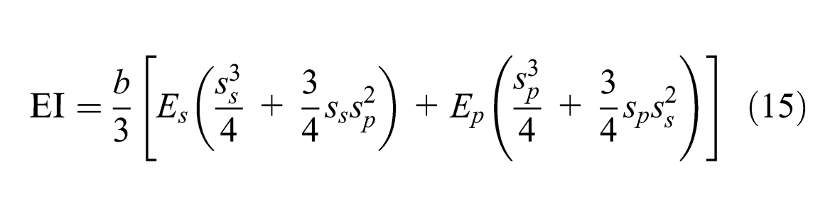
where
The vibration response relative to the base for the composite cantilever beam can be presented by a series of eigenfunctions
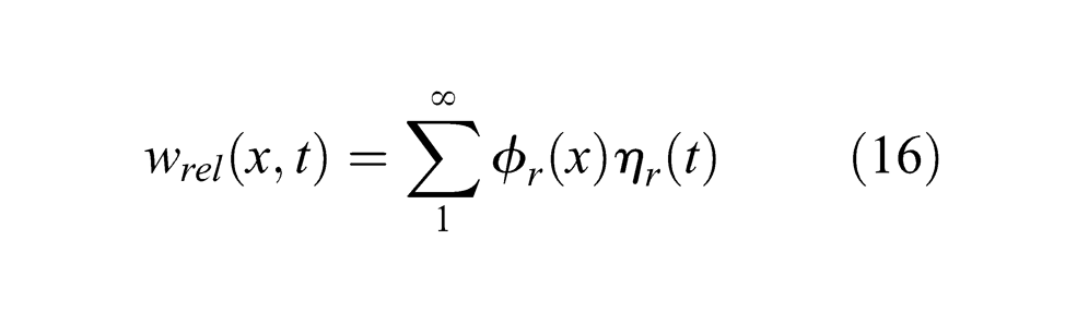
where
By applying the orthogonality conditions of the eigenfunctions and ignoring the viscous air damping, the equation of motion in the modal coordinates can be obtained. As a result, equations (13) and (14) can be rewritten as
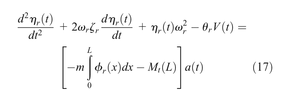
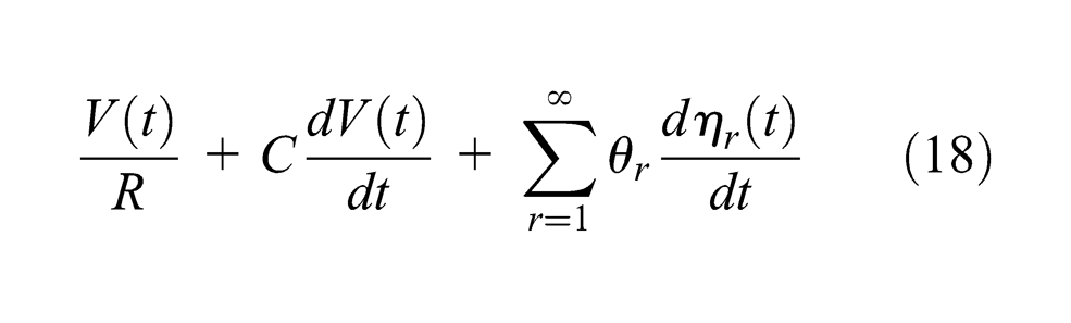
where
For the cantilever beam with a single piezoelectric layer
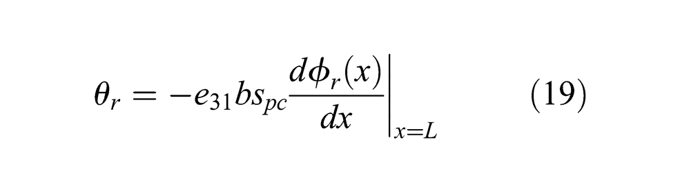
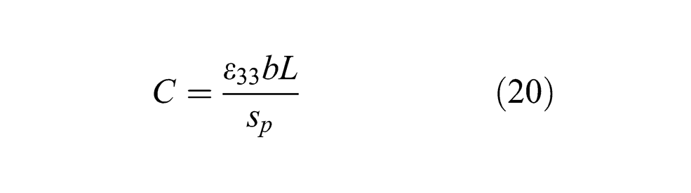

where
For a harmonic base acceleration
Energy harvesting for bridges with one vehicle passing through
This section analyzes the energy harvesting for bridges when only one vehicle passes through the bridges. The vehicle and four different bridges as described in section “Bridge–vehicle system modeling” are used. Seven different vehicle speeds ranging from 30 (18.75 mile/h) to 120 km/h (75 mile/h) with an interval of 15 km/h are adopted. Five road surface conditions, “very poor,”“poor,”“average,”“good,” and “very good,” are used for the bridge pavement (ISO 8608:1995, 1995).
The parameters of the piezoelectric cantilever–based harvesters are listed in Table 3. The piezoelectric patch P-876.A12 from PI Ceramic is used for the harvester. The dimensions of the cantilever beam are chosen to match the patch size. For the fairness of comparison among the harvesters, all the parameters except the stiffness of the substructure are kept the same for all the energy harvesters studied in this article. By adjusting the stiffness of the substructure, the fundamental natural frequency of the harvester is tuned correspondingly to the dominant vibration frequency of a host bridge. The dominant frequency of the bridge is defined as the vibration frequency of the bridge with the largest amplitude in the frequency domain spectrum. It should be noted that the dominant vibration frequency of the bridge is not necessarily the same as the fundamental natural frequency of the bridge (Table 1) although they are identical in many cases.
Parameters of piezoelectric cantilever–based energy harvester.
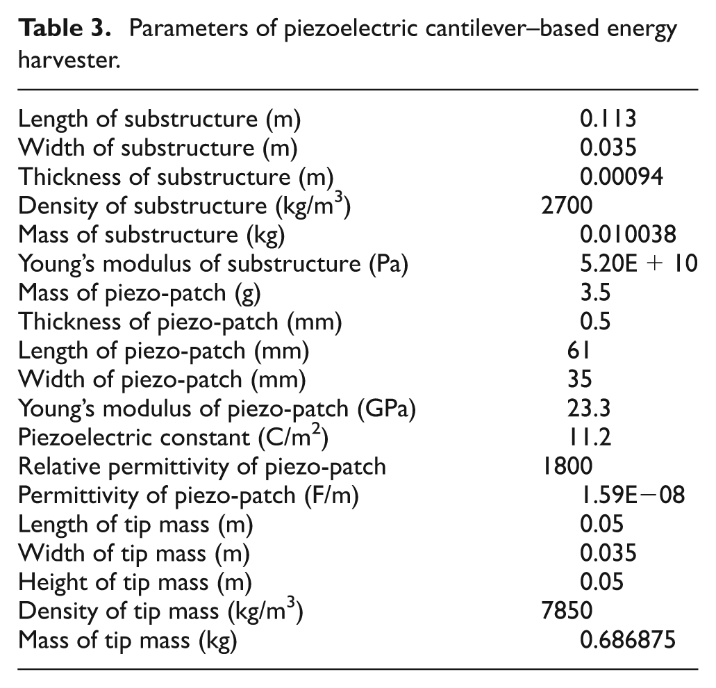
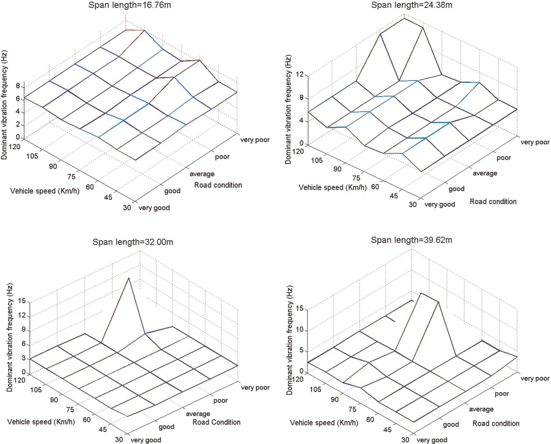
Figure 4 shows the dominant vibration frequencies of the bridges with different road conditions and with passing vehicles at different speeds. For a dynamic system, it is true that its fundamental vibration mode is easier to be triggered than other vibration modes. However, as shown in Figure 4, the dominant vibration frequencies do not always coincide with the fundamental natural frequencies of the four bridges. It can be found that the bridges are more likely to vibrate at a higher frequency with a poorer road condition and a higher vehicle speed.
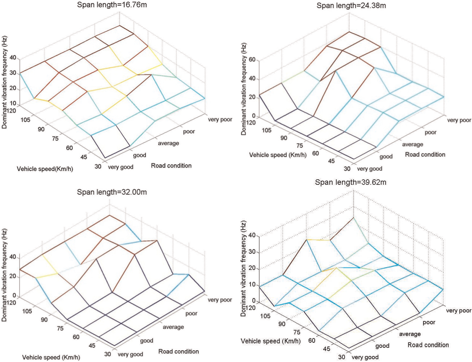
Dominant vibration frequencies under one passing vehicle condition for the bridge with (a) 16.76m span length (b) 24.38 m span length (c) 32.00m span length and (d) 39.62 m span length.
For the case with only one vehicle passing through the bridge, the simulation starts when the vehicle reaches the bridge and ends when the vehicle leaves the bridge. Therefore, there is a vehicle–bridge interaction all the time during the process. It is more like a forced vibration for the bridge through the simulation. During a forced vibration, the dynamic load frequency, which is the frequency of the contacting force between the bridge and the vehicle, is a crucial factor that determines the dominant vibration frequency of the bridge. When the dynamic load frequency is close to a high natural frequency of the bridge, a high-order vibration mode is likely to be triggered. As a result, the dominant vibration frequency is not necessarily the fundamental natural frequency of the bridge.
The main dynamic load frequency is affected by the product of the vehicle velocity and the cutoff values of the road roughness spatial frequency (Li and Su, 1999). The spatial frequency is a measure of how often the sinusoidal components (as determined by the Fourier transform) of the structure repeat per unit distance. Therefore, the product of the vehicle velocity and the cutoff values of the road roughness spatial frequency,
Besides, the roughness of surface also influences the dominant vibration frequency of the bridges. The vibration of a bridge is very complicated and consists of a series of vibrations at different frequencies. As discussed earlier, the dominant frequency is determined by the vibration frequency of the bridge with the largest amplitude in the frequency domain spectrum. When the road condition is better, the impact force becomes smaller. Although it can still trigger high-mode vibration, the high-mode vibration contributes a smaller part in the entire vibration of the bridge. As a result, when the road condition becomes better, it is more likely that the dominant vibration frequency is determined by the fundamental vibration mode rather than the high vibration mode triggered by the impact force.
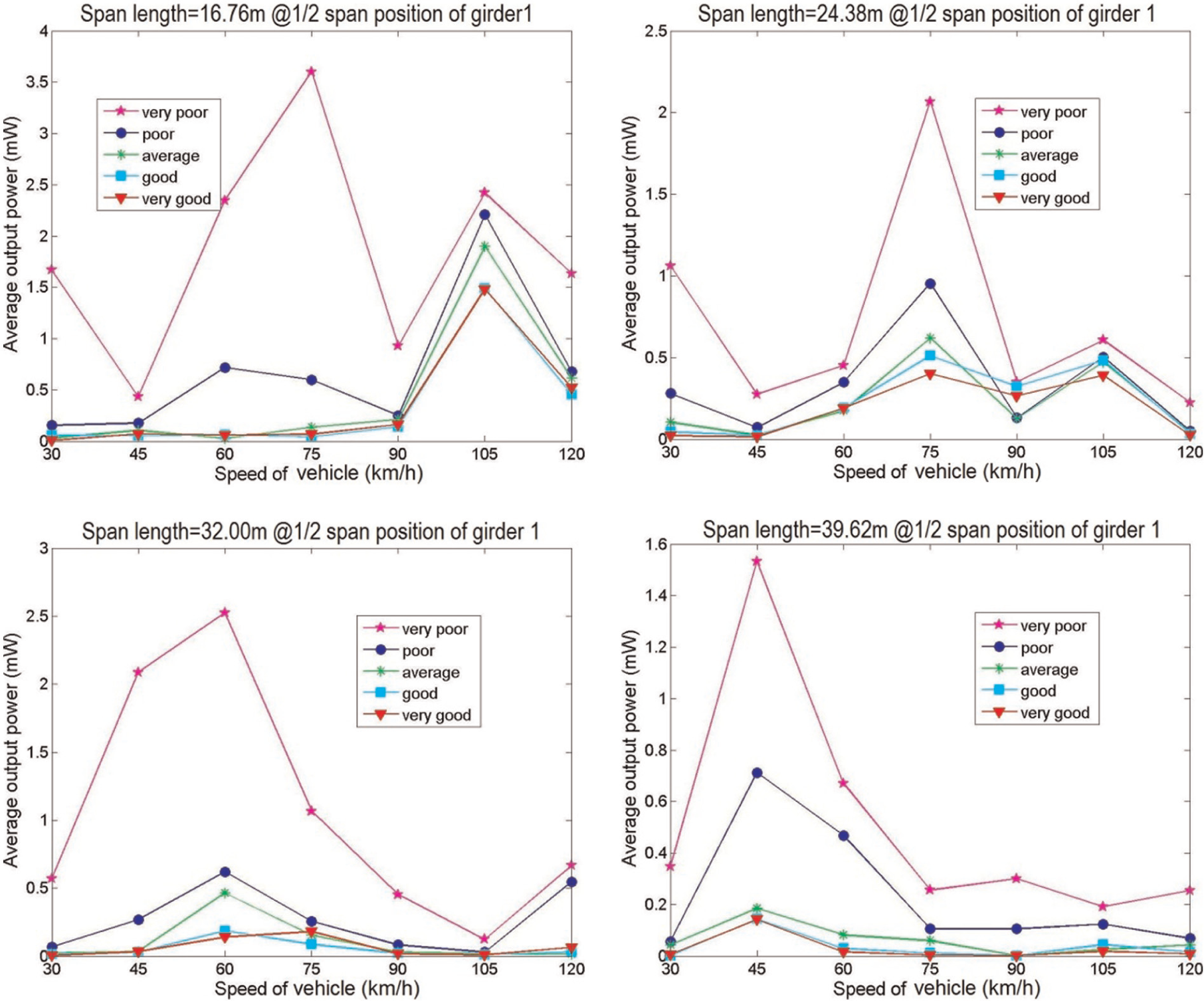
Figure 5 shows the average harvesting output power from the harvester located at the 1/2 span position of girder 1 with only one vehicle passing through the bridge. The average energy output power is defined as the time average power through the load resistor R during the entire simulation process and the definition is used throughout this article. From Figure 5, it can be found that a higher output power can be obtained at poorer road surface conditions. It can be explained by the fact that a poorer road condition causes a larger dynamic loading and therefore can input more energy into the bridge through the contacting force between the bridge and vehicle. However, not all the harvesters follow the same trend exactly. In Figure 5, the output power under a poorer road condition is not necessarily larger than the one under a better road condition with the same vehicle speed. For example, at a vehicle speed of 45 km/h, the output power for the 32 m long bridge under the “poor” road condition is larger than the output power for the “very poor” road condition. This disorder is caused by the sensitivity of the harvester to the excitation vibration frequency. The performance of the piezoelectric cantilever harvester strongly depends on the accordance with the resonant frequencies.
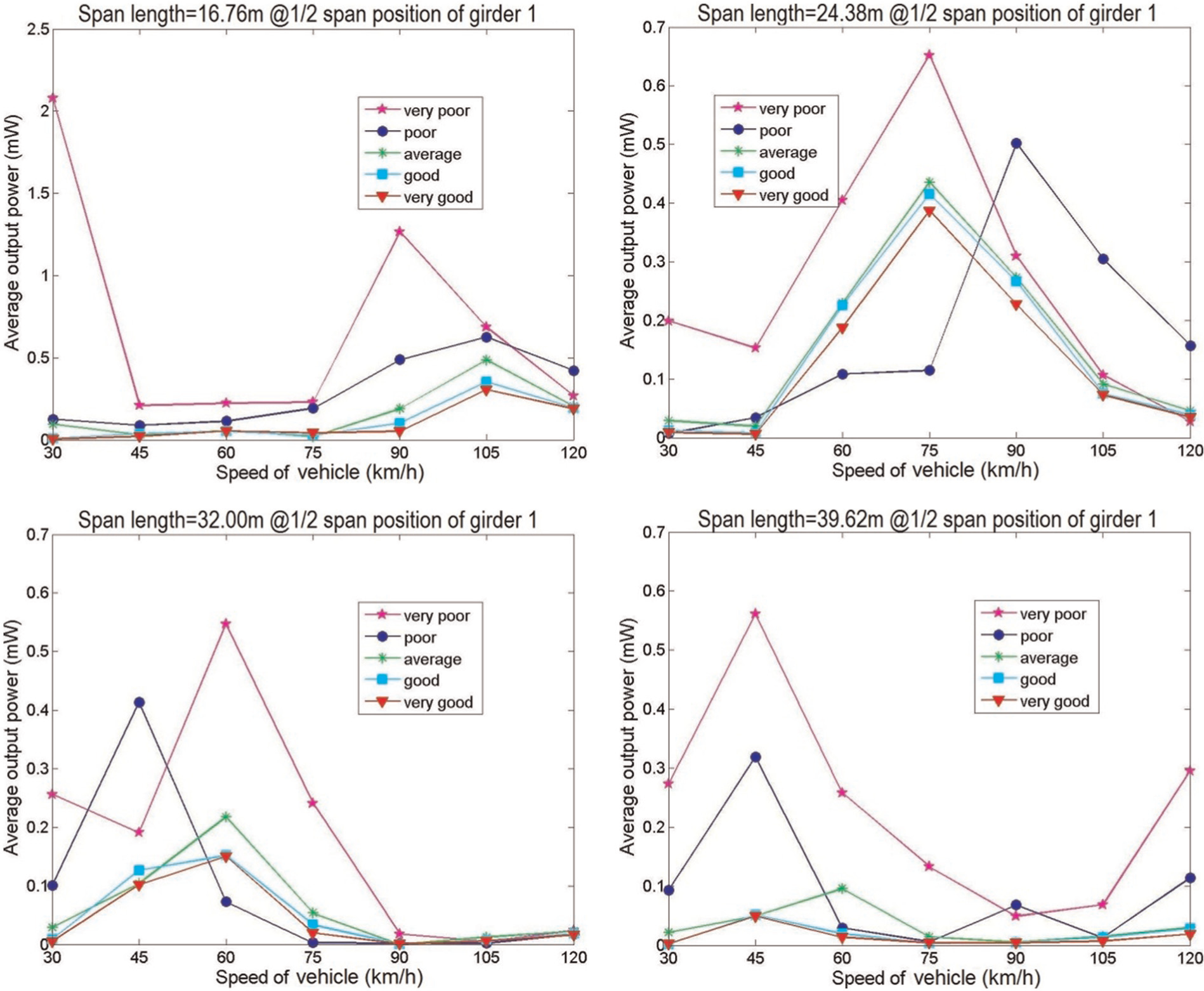
Average output power from the harvester at the 1/2 span position of girder 1 on the bridge with (a) 16.76m span length (b) 24.38 m span length (c) 32.00m span length and (d) 39.62 m span length.
Since the damping of a piezoelectric cantilever harvester is usually minimized to reduce any energy loss, the bandwidth of the harvester is very small. When the fundamental natural frequency of the harvester matches the excitation vibration very well, the output power can increase dramatically. In contrast, the output power can be much lower with an unmatched resonant frequency. In the simulation, all the harvesters are tuned to the dominant vibration frequency of the bridge vibration. However, the vibration of a bridge is more or less random, and a dominant frequency does not always obviously exist. For example, when the dominant frequency can be obviously found as shown in Figure 6(a), indicating that most kinetic energy concentrates on this dominant frequency vibration, the harvester can be easily tuned to match this dominant frequency and therefore provide a high output power. However, under vibrations without an obvious dominant frequency as shown in Figure 6(b), indicating that the kinetic energy distributes more uniformly in the vibrations of different frequencies, the output power of the harvester is much lower even though the fundamental natural frequency of harvester matches the dominant vibration frequency.
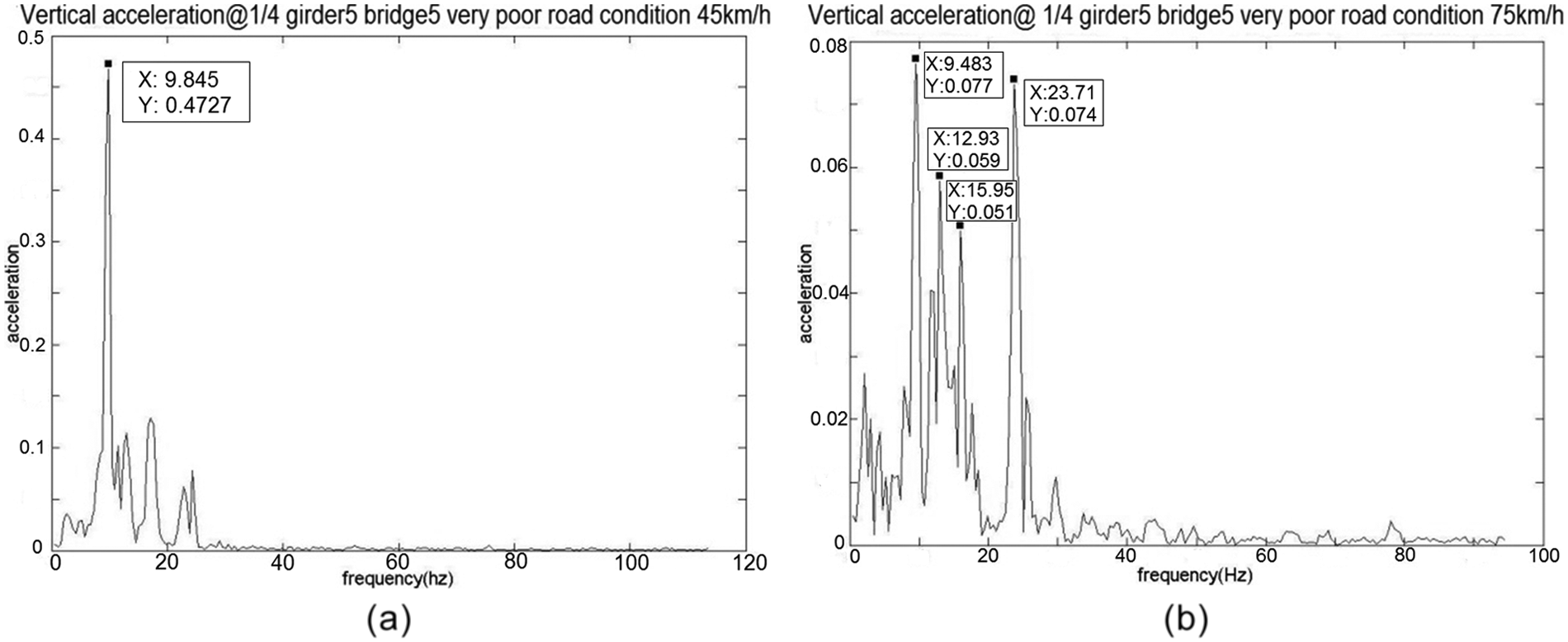
Vertical accelerations in frequency domain for (a) very poor road condition with 45km/h vehicle speed and (b) very poor road condition with 75km/h vehicle speed.
From another perspective, it can be inferred that the robustness of the piezoelectric cantilever harvester can be a big issue for energy harvesting in bridge structures. Vibration with several peak frequencies as shown in Figure 6(b) is very common for a bridge structure. A harvester with a larger bandwidth can cover a wider frequency range and collect more kinetic energy from the vibration of a bridge. To improve the robustness of vibration-based energy harvesters, some studies have been done in recent years. Generally, there are three major ways for obtaining a lager bandwidth and improving the robustness: nonlinear stiffness (Hajati and Kim, 2009; Mann and Sims, 2009; Marinkovi and Koser, 2009), bi-stable vibration (Arrieta et al., 2010; Ferrari et al., 2010; Formosa, 2009; Jung and Yun, 2010; Mann and Owens, 2010), and multiple harvesters (Erturk et al., 2009; Shahruz, 2006a, 2006b).
A higher vehicle speed brings larger kinetic energy to the vehicle but does not necessarily increase the harvesting output power. According to the theory of resonant speed for railway bridges (Li and Su, 1999), the largest dynamic loading is obtained at a peak speed, which is usually not the highest speed. The details of the theory are discussed later. Also, with a higher vehicle speed, the dynamic loading has more peaks appearing at its high frequency range. The higher vehicle speed tends to generate a wider frequency band (Shi, 2006). The wider frequency band of vibrations can dramatically decrease the harvesting output power of the harvester because the bandwidth of the piezoelectric cantilever–based harvester is too small to efficiently cover a wide frequency range. Meanwhile, when the kinetic energy is decentralized among a series of vibrations with different frequencies, the energy in any single frequency vibration is small. Therefore, the harvesting output power does not increase necessarily as the vehicle speed increases. An optimum speed at which the harvested output power reaches the maximum can usually be observed.
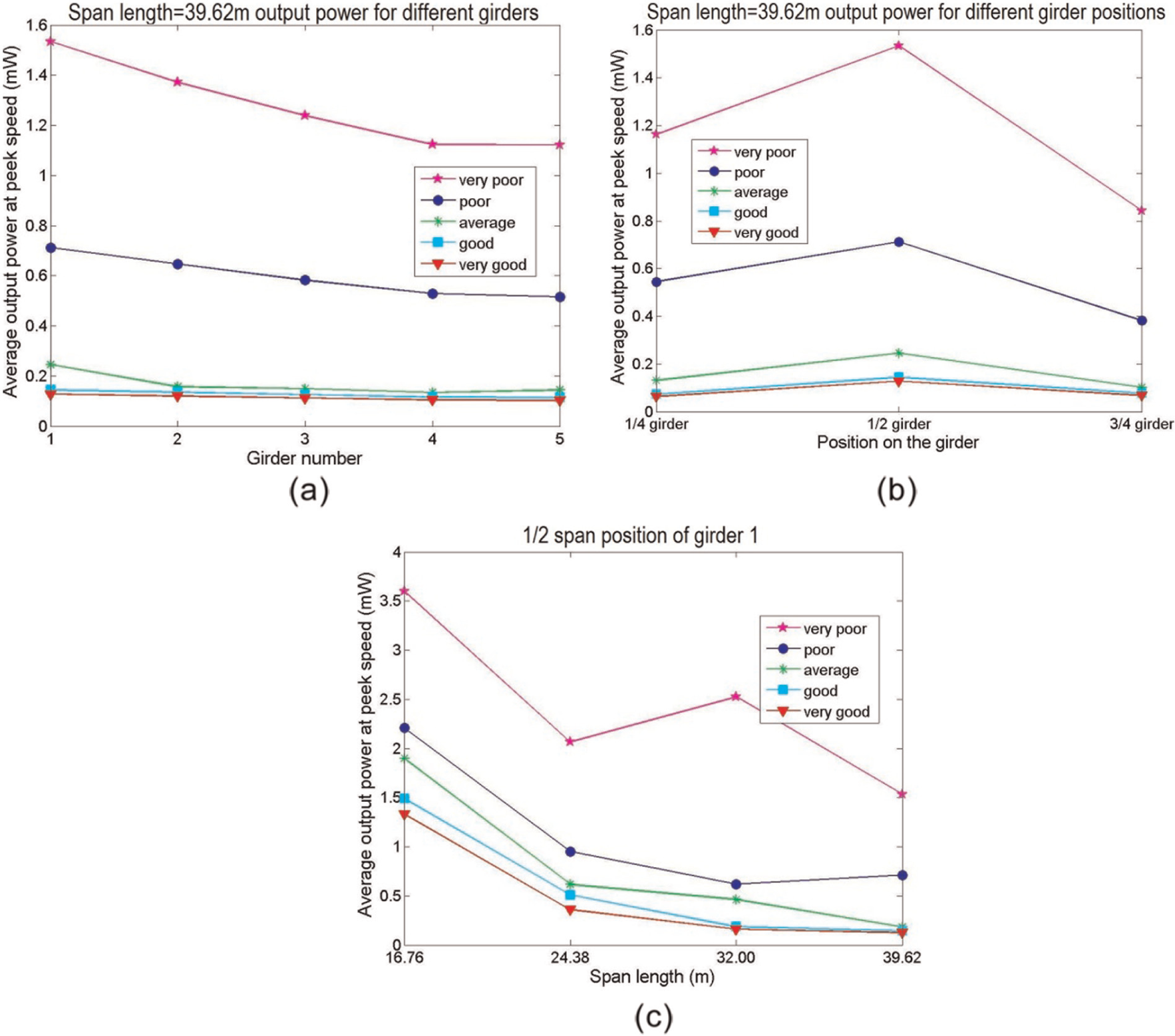
To analyze the influence of the span length and harvester position on the energy harvesting performance, the energy output powers at the optimum vehicle speeds are summarized and plotted in Figure 7. The span length is fixed when the harvester position is analyzed, and correspondingly, the harvester position is fixed when the effect of the span length is analyzed. Since the truck passes the left side of the bridge, which is close to girders 1 and 2, the dynamic loading decreases from girder 1 to girder 5. As a result, the harvesting output power drops in the same order, which can be found in Figure 7(a). From Figure 7(b), it is obvious that harvesters placed at the mid-span provide the highest harvesting output power. Not only the largest displacement but also the largest dynamic loading occurs at the mid-span, which gives the harvester there the highest energy input. The harvesting output power decreases slightly with an increasing span length according to Figure 7(c), mainly due to the decrease of the bridge vibration frequency with a longer span length. From Figure 4, although higher vibration modes are triggered for all the four bridges, shorter bridges are more likely to vibrate at higher frequencies. The piezoelectric cantilever–based harvester benefits from the high-frequency vibrations with which it has higher strain changing rate on the piezoelectric layer and therefore has better harvesting performance.
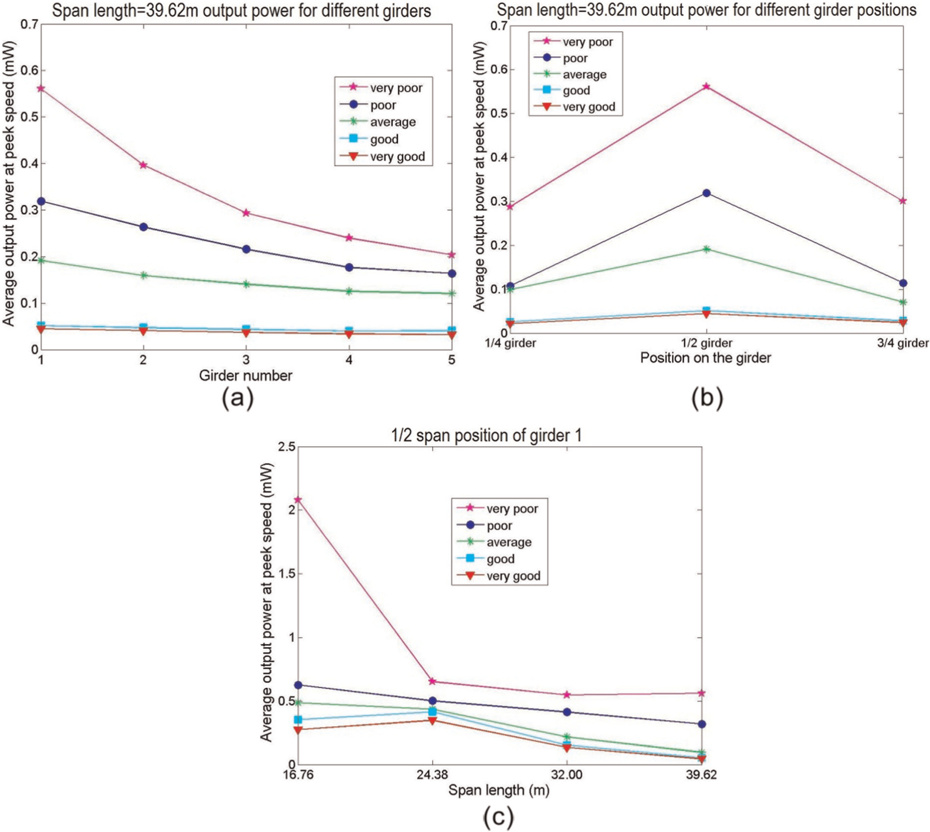
Average output power for the bridges with one passing vehicle versus (a) different girders, (b) different girder positions, and (c) different span lengths.
Energy harvesting for bridges with continuous vehicles passing through
To make it closer to the reality, simulations for the bridges with continuous passing vehicles are conducted. In this study, the vehicles pass the bridges one after another with a constant time interval and identical speed.
For the bridges with one passing vehicle, the bridges tend to vibrate at higher frequencies than their fundamental natural frequencies. However, with continuous passing vehicles, the dominant vibration frequencies of the bridges are determined by their fundamental natural frequency, which corresponds to their first symmetric bending mode. It can be seen from Figure 8 that in most cases, the dominant frequencies of the four bridges are 6.5, 4.5, 3.2, and 2.6 Hz, respectively, which are exactly the same as their fundamental natural frequencies (Table 1). Several exceptions can be found for the poor or very poor road conditions with high vehicle speeds. For the bridges with one passing vehicle, their vibrations are forced vibration during the entire simulation process. As a result, the vibrations are partially determined by the dynamic loadings on the bridges. However, the vibrations of bridges with continuous vehicles include not only the forced vibration part but also the free vibration part. Although higher order of vibration modes of the bridges may be excited when the vehicles are passing through them, without vehicles on them, the bridges tend to vibrate at their first vibration mode during the subsequent free vibration stage (Figure 9). Therefore, with a large part of free vibrations, the dominant vibration frequencies of the bridges are typically the same as their fundamental natural frequencies.
Dominant vibration frequencies under continuous passing vehicles condition for the bridge with (a) 16.76m span length (b) 24.38 m span length (c) 32.00m span length and (d) 39.62 m span length.
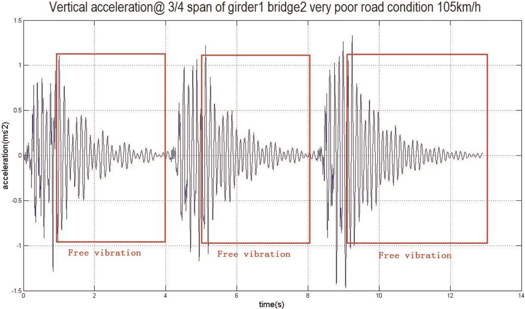
Vertical acceleration in time domain.
Figure 10 shows the average harvesting output power from the harvesters located at the 1/2 span length of girder 1 with vehicles continuously passing through the bridges. Since most of the dominant vibration frequencies are the same for the bridge with a same span length, the effect of harvesting sensitivity to the vibration frequency is largely eliminated. The relationship between the road condition and output power and the one between the vehicle speed and output power become more obvious. It can be observed that the poorer road condition results in a higher harvesting output power, which is shown and discussed earlier.
Average output power from the harvester at the 1/2 span position of girder 1 on the bridge with (a) 16.76m span length (b) 24.38 m span length (c) 32.00m span length and (d) 39.62 m span length.
Optimum speeds for the maximum output power can also be observed from Figure 10. For the bridge with a 16.76 m span length, a vehicle speed of 105 km/h gives the highest power for all road conditions except the condition of very poor. Besides, 75, 60, and 45 km/h are the peak speeds for bridges with a span length of 24.38, 32.00, and 39.62, respectively. The peak speed can be explained by the following equation
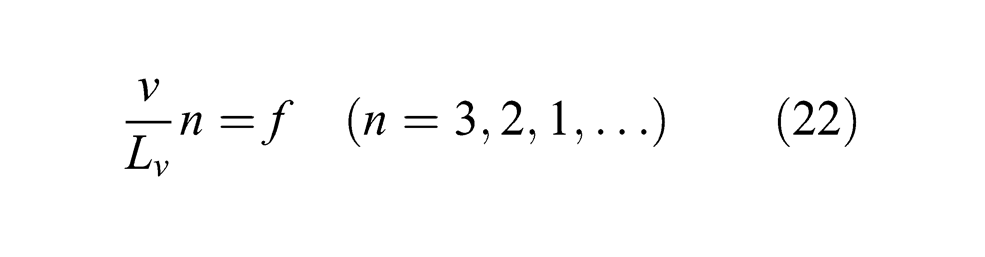
where
Equation (22) was originally used to explain the train resonant speed for railway bridges (Li and Su, 1999). Theoretical and numerical studies on railway bridges have shown that when n times the frequency component due to a series of moving loads is equal to the natural frequency of a bridge, the resonant effect will occur.
Substituting the bridge fundamental frequencies shown in Table 1 and HS20 truck load axle spacing of 4.26 m into equation (22), the calculated peak vehicle speeds are 101, 71, 49, and 41 km/h for the bridges with a span length of 16.76, 24.38, 32.00, and 39.62 m, respectively. The results match well the peak speeds observed from Figure 10. This consistency can be explained by the theory of resonant speed for railway bridges. Although the number of axle loads of the truck is much less than that of a train, the multi-axle truck loads can still be considered as repeated loads on short bridges. When the vehicle reaches the bridge, the first axle load impacts the bridge and then the second axle load repeats the impacting. When the load repeating frequency matches the fundamental natural frequency of the bridge, resonant vibration is easier to be triggered for the bridge–vehicle system and therefore produces much higher vibration energy for energy harvester to collect.
Figure 11 shows the effect of the harvester position and span length on the harvesting output power. A same trend can be found as discussed earlier in Figure 7. It should be noted that the harvesting output power increases more steeply with a shorter span length than in the case of a single passing vehicle discussed earlier. The reason for the steeper increase is that the differences among the dominant vibration frequencies of the four bridges are larger in the scenario with continuous passing vehicles than those in the scenario with only one vehicle. It should also be pointed out that although the dominant vibration frequencies are higher for the bridges with one vehicle than the ones with continuous vehicles, the resonant vibration of the bridges happens in the later situation and allows longer time for the harvesters to reach their resonant vibration status. As a result, the harvesting output powers from the bridges with continuous vehicles are much higher than the ones with one vehicle.
Average output power for the bridges with continuous passing vehicles versus (a) different girders, (b) different girder positions, and (c) different span lengths.
As for applications, the piezoelectric energy harvester can be used to power sensor nodes in a wireless sensor network for bridges or other civil infrastructures. A sensor node usually performs four basic important activities in a sensor network, including serving as a sensing unit, a processing unit, a transceiver unit, and a power unit (Dutta et al., 2012). Among all the units except for the power unit which is the power source, the transceiver unit is the major energy-consuming component since the communication is one of the most energy expensive tasks (Schurghers et al., 2002). It is generally true that micro-electro-mechanical system (MEMS)-based sensing unit consumes negligible power compared to other components in a sensor node (Kompis and Aliwell, 2008). The data processing unit also consumes much less energy than the transceiver unit. For example, the energy consumption of transmitting a single bit is approximately the same as processing thousands of instructions in a sensor node (Kaiser and Pottie, 2000). Therefore, the power demand of a sensor node is basically determined by the wireless transmission energy consumption. The transmission consumption level depends on the communication distance and communication quality such as signal–noise ratio; 200 μW is considered to be the absolute minimum power demand for an energy harvesting device in the application of a sensor node (Kompis and Aliwell, 2008). The simulation results show that the minimum requirement can be satisfied or approached closely enough in most scenarios. It indicates that the piezoelectric energy harvesting can be a potential power source for sensor nodes in a wireless sensor network. In a realistic application, the power consumption of a micro-sensor node ranges from 1 mW to 10s of mW (Chen et al., 2012; Park et al., 2008). Even with a micro-operating system, the node can be intentionally switched on or off to save energy; the harvested energy as calculated in the previous sections is barely enough for the routine use of the sensor nodes. In the best scenario, very poor road conditions with heavy traffic, the energy harvester studied in this article can only support the nodes with a low power demand. However, it should be noted that the power required by a sensor node and the power provided by the piezoelectric energy harvester are in the same order of magnitudes. By improving the formation of the harvester such as using multi-impact harvester (Zhang and Cai, 2012) or increasing the piezoelectric material area or energy transfer efficiency, piezoelectric energy harvesting could become a sustainable power source in wireless sensor networks for civil infrastructures.
Discussion and conclusion
The development of wireless sensor networks not only provides a promising way for structure health monitoring but also brings an urgent challenge on its power supply. Piezoelectric-based energy harvesting is a sustainable power source that can potentially solve this problem. However, applying piezoelectric energy harvesters on civil infrastructures has its own unique problems considering the properties of both the infrastructures and the harvesters. Due to the internal capacitance of the piezoelectric material, the circuit with a piezoelectric harvester will act as a high-pass filter, which will lower the harvesting performance when the frequency of external vibrations is low. Also, the wide vibration frequency range of civil infrastructures will decrease the efficiency of the piezoelectric energy harvester.
To obtain a better understanding and prediction of the energy harvesting on civil infrastructures, this article examines the performance of piezoelectric cantilever–based harvesters on four concrete slab-on-girder bridges. Different from other research that adopted idealized harvester models or simplified bridge models, detailed harvester and bridge models are used in this study. The adopted harvesters have the most widely used formation, and the bridges are representative of the majority of the bridges in the United States. Other properties such as harvester positions, bridge road roughness, girder length, and vehicle speeds are fully considered to draw a more realistic and meaningful conclusion for potential applications.
In this article, only passing vehicles are considered as the external load that excites the bridges to vibrate. The dominant vibration frequencies of the bridges are defined and calculated regarding the two different scenarios. Matching the dominant vibration frequency is critical for the energy harvester to obtain a maximum output power. From the study, the dominant frequencies of the four bridges are all lower than 10 Hz when there are continuous vehicles passing through them. With a larger span length, the dominant frequency of a bridge can be even lower. It shows one of the major challenges for energy harvesting in a bridge or other civil infrastructures: the ultra low dominant vibration frequency. The low dominant frequency decreases the energy harvesting efficiency dramatically since the low vibration frequency reduces the strain changing rate on the piezoelectric layer. Therefore, an improved harvester with better low-frequency performance is required for its application in civil infrastructures.
It is also observed that vehicles with a high speed can trigger several higher orders of vibration modes of a bridge, which give the vibration a wide frequency range and lower the harvesting output power as a result. Therefore, wider usable frequency range is also crucial for energy harvesting in civil infrastructures. Besides, the effects of road condition, span length, harvester position, and vehicle speed on the energy harvesting performance are also studied and discussed. The road condition shows a considerable influence on the energy harvesting performance, which was not studied by previous research. Optimum vehicle speeds for the maximum harvesting output power have also been found and studied, which indicate that a higher vehicle speed does not necessarily lead to a larger harvesting output power. In this study, the simulated output power provides a more realistic prediction for the energy harvesting under various conditions. Although there are various kinds of bridges and piezoelectric energy harvesters, the selected bridges and harvesters are the most widely used ones, which are very representative. The simulation can provide guidance for the design and applications of piezoelectric-based energy harvesters aimed on civil infrastructures. The simulation results show that the obtained output power can satisfy or approach the minimum power demand for the sensor nodes. It is feasible for piezoelectric energy harvesting to power the wireless sensor network in civil infrastructures. However, the performance of the energy harvesting at low frequencies and under excitations with wide frequency range needs to be improved to support a routine use of wireless sensor nodes. A study to improve the energy harvesting on bridge vibrations by using a multi-impactor is under way in our research group.
Footnotes
Declaration of conflicting interests
The authors declared no potential conflicts of interest with respect to the research, authorship, and/or publication of this article.
Funding
This research received no specific grant from any funding agency in the public, commercial, or not-for-profit sectors.