
Abstract
A model of motion of an agonistic–antagonistic shape memory alloy actuator is developed in this article. The model shows that the dynamics of the actuator can be well described by a nonlinear motion model of human muscle with nonlinear damping. To complete the model, a method for the determination of the damping properties of the actuator system is suggested. To this end, an analytical expression for the damping coefficient of the system was developed. The experimental verification of the proposed model of motion was conducted through a comparison of the experimentally measured and numerically simulated step responses. The simulated step responses were in close agreement with their experimentally measured counterparts on the shape memory alloy actuator prototype.
Introduction
The NiTi shape memory alloy (SMA) actuator of interest represents a monolithic device that is capable of developing relatively large displacements in space-constrained applications under the application of heat loads to the actuator. A conceptual design of such a device was described in one of our previous publications (Malukhin and Ehmann, 2007) and is shown in Figure 1.
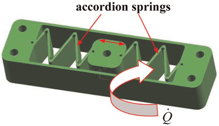
Conceptual design of a monolithic actuator—linear stage.
The monolithic actuator represents an agonistic–antagonistic NiTi SMA actuator that can develop large linear displacements by means of a contracting/stretching motion of the accordion spring structures shown in Figure 1. The large displacements can be developed due to the so-called shape memory effect (SME) that takes place during reverse temperature-induced phase transformation in the SMA material of the actuator. The reverse temperature–induced phase transformation in the SMA material is the consequence of the change of its crystallographic structure with the increase of the temperature of the material. During this phase transformation, the SMA material changes its phase state from twinned martensite to austenite, while the SMA structure can develop a corresponding recovery (or SME driven) motion. This is achieved by the application of heat flux
There exist a number of models for NiTi SMA actuators in the literature that are used for control purposes. Many of the models implement conventional proportional–integral–derivative (PID) or proportional–derivative (PD) control methods (e.g. Chanthasopeephan and Jairakrean, 2009; Heinonen et al., 2008). Although, due to the nonlinear nature of the properties of SMAs and consequently of their performance, the successful control models usually implement nonlinear control methods such as adaptive fuzzy control logic methods, for example, Tai and Ahn (2010) and Kannan et al. (2010); variable structure control as described in Elahinia and Ashrafiuon (2002); cascade control (Léchevin and Rabbath, 2005); combined PID control and a duty cycle hysteresis compensator (Wang et al., 2012); or the adaptive control methods used to control SMA actuator motion in Webb and Lagoudas (1998) and Janaideh and Bernstein (2013). Another group of control methods employs SMA actuator models that take into account the nonlinear properties (e.g. hysteresis) of the SMA materials. These models are further linearized and incorporated into conventional PID controllers (or, for example, sliding mode controllers) of the SMA actuators using Lie algebra, as shown in the work of Benzaoui et al. (1999). The authors use Lie algebra to develop a control law of an SMA actuator. They employ a state representation of the SMA actuator system and implement the so-called Lie derivatives to linearize the SMA actuator model, thus avoiding a heuristic approach. They also show that this linearization technique itself imposes additional limitations on the controlled system (the SMA actuator in this case). For example, the limitations could originate from inversion of the Lie derivatives. In addition, this control approach requires knowledge of all the system states and involves a state estimation procedure if not all the state variables can be measured. The above-mentioned models could sometimes be very complex due to the hysteretic behavior and the time-dependent properties of the SMA materials. Therefore, G´edouin et al. (2008) suggested a derivative-estimation-based “model-free” control of the SMA actuator’s motion. According to G´edouin et al. (2008), the suggested “model-free” control method does not require prior knowledge of the SMA properties and is robust against noise. On the contrary, the current work suggests a unique and robust model of an SMA wire-based actuator that does not require its further linearization for control purposes and relies only upon the fundamental physical properties of the SMA material, energy conservation laws, and minimal semi-heuristic qualitative knowledge of the dynamics of the actuator’s response under certain load conditions. Based on the latter criteria, a model of motion is developed in this work that offers the possibility of deriving corresponding control laws in future research.
A mathematical model of the SME-driven motion of an agonistic–antagonistic SMA actuator was introduced in our previous studies (Malukhin and Ehmann, 2007). The current article represents an advanced description of the model of motion powered by a description of a method for the determination of the damping coefficient of the actuator system. The model also utilizes a new mathematical model of the kinetics of the reverse temperature–induced phase transformation in NiTi SMAs (Malukhin and Ehmann, 2012) and an existing model of nonlinear motion of a human muscle (Wu et al., 1990). The model of the kinetics is used in order to determine the SME-induced driving force (recovery force) that is an input to the model of motion. The new contribution of this work lies in the fact that the suggested model of motion combines a nonlinear (curve-fit based) human muscle motion model with a nonlinear damping model and a new reverse temperature-induced phase transformation model. Since the fundamental properties of the SMAs to undergo the phase change are used in the model of motion, it makes the model more robust than other existing models of motion. The model does not depend on the hysteresis property knowingly present in similar SMA structures because only the reverse temperature-induced phase transformation property of SMAs is used here, thus increasing the significance of the model applied to specific working conditions.
In this work, only the reverse phase transformation will be considered to simplify the suggested model of motion, since the SME-driven motion is achieved only during this kind of transformation in the SMA structure. As a consequence, the suggested model will have certain limitations due to the fact that not all possible initial crystallographic, temperature, and stress states of the actuator’s material are considered.
An important unknown parameter in the model of motion is the actuator’s damping coefficient. Current theories of damping show a lack of robust, reliable, and unified methods that can be used to identify the damping properties of the system (Phani and Woodhouse, 2007). According to Gaul (1999), damping can be classified as (1) material damping, (2) structural damping, (3) radiation damping, (4) active/passive damping (including semi-active and hybrid damping according to Preumont and Seto (2008), and (5) internal/external damping. In this study, we will consider material damping only, although SMAs can be modeled as active or passive dampers as well (Preumont and Seto, 2008).
In general, damping can be subdivided into four types: linear, nonlinear, viscous, and non-viscous damping (Adhikari and Woodhouse, 2001; Gaul, 1999; Staszewski, 1997). There exist a number of well-defined and known models and methods for the identification of damping properties that are mostly aimed at the determination of the linear viscous damping properties used in the description of a system that undergoes small vibrations. For example, (1) matrix methods, where a damping matrix proportional to the stiffness or mass matrix is introduced (Gawronski, 2004); (2) modal methods, where damping coefficients are introduced in the corresponding modal equations; and (3) enhanced matrix methods and others (Adhikari and Woodhouse, 2001; Gaul, 1999; Preumont and Seto, 2008). Identification of linear non-viscous damping properties can be undertaken using similar methods to the above, but with implementation of different damping approximation techniques (Adhikari and Woodhouse, 2001; Woodhouse, 1998). These methods are currently used as a rough approximation in the identification of the damping properties of other types of systems that exhibit nonlinear damping behavior. Therefore, there is a need for the development of a comprehensive theory of damping that can account for all existing types of damping and can be used to model different systems with diverse system properties.
SMAs are nonlinear materials, thus exhibiting nonlinear and non-viscous damping properties. Wu et al. (2007) used a modified modal method of damping identification in order to determine the nonlinear damping of a particular damping aluminum alloy. Another similar way of identification of the nonlinear (hysteretic) damping of a rubber material is described by Sun et al. (2010). Researchers in Heinonen et al. (2008) have developed a semi-active mechanism aimed at the reduction of structural vibrations using an SMA wire actuator. The authors identified the damping of their mechanism by means of static and dynamic tests by computing the ratio of the magnitudes of the dissipation and external works.
As it was mentioned before, all the discussed damping models rely on system identification procedures, powered by different types of approximation methods of the damping and other parameters used in the identification procedure. Therefore, it is clear that currently, a more or less well-understood procedure of the damping identification must include both a combination of experimental and numerical techniques.
In this study, a simplified method of identification of damping was undertaken, where the damping coefficient is determined by integrating the differential equation of motion of the SMA actuator. It was possible to implement such a method because the equation of motion of the SMA actuator can be solved analytically with respect to the damping coefficient, aided by the knowledge of the intrinsic properties of the SMA material, namely, its austenite phase transformation function. Therefore, the suggested method can be applied only to similar motion systems.
The suggested model of motion will be validated using an SMA wire actuator, which represents a simplified prototype of the SMA spring actuator shown earlier in Figure 1. A schematic representation of the SMA wire actuator will be described in the next section and is shown in Figure 2. An example of the numerical simulation of the step response of an SMA wire actuator and its experimental verification will also be given. Additionally, the analytical expression for the damping coefficient will be evaluated based on the experimentally measured step response of the actuator. This simplification, however, does not diminish the generality of the considerations, since modifications in the motion model will only relate to the geometry of the actuator.
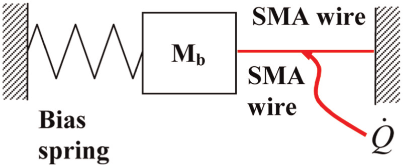
Schematic representation of the agonistic–antagonistic actuator.
To summarize, the suggested model of motion of an SMA actuator is based on the fundamental physics-based force balance equation with one nonlinear (curve-fit based) damping term. Input force data to the model of motion are derived from the earlier developed energy-balance-based phenomenological model of temperature-induced phase transformation kinetics in NiTi SMAs described in Malukhin and Ehmann (2012). The motion model in its suggested representation is not intended to be used for control purposes, but only as a descriptive tool aimed at quantitative and qualitative characterization of the SMA actuator mechanics and dynamics.
Currently, the suggested SMA actuator motion model can be used in applications requiring modeling of the SME recovery motion only as, for example, in the SMA wire-based hexapod model developed by Fevrier et al. (2013). In our future research, the suggested motion model will be modified such that it can be used in order to control the motion of the SMA spring actuator shown in Figure 1.
Model of motion of the SMA actuator
The simplified actuator (Figure 2) represents an agonistic–antagonistic (i.e. containing a pair of active and passive elements) type of actuator. The active element (e.g. SMA wire or SMA spring) is connected in series to the passive element (e.g. bias spring) through a payload mass Mb. The passive element (the bias spring) creates a pretension of the active element by stretching it before actuation. When the active element (SMA wire) is pre-stretched, a heat load
Preliminary experimental investigations of the motion of a simple SMA wire-based actuator (Malukhin and Ehmann, 2007) have indicated that the actuator motion qualitatively resembles the contraction motion of human muscle (Wu et al., 1990). For example, Figure 3 shows the step response of an SMA wire-based actuator, taken from our previous work (Malukhin and Ehmann, 2007). A step response of both a human muscle described in Wu et al. (1990) and our experimental data depicted in Figure 3 (Malukhin and Ehmann, 2007) show a typical step response dynamic behavior and are qualitatively similar due to the presence of two characteristic regions: (1) a region where the response is fast at the beginning of the time interval and (2) a region where the response is slow and is being stabilized at the end of the time interval.
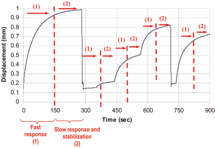
Experimental step response of SMA wire-based actuator (Malukhin and Ehmann, 2007).
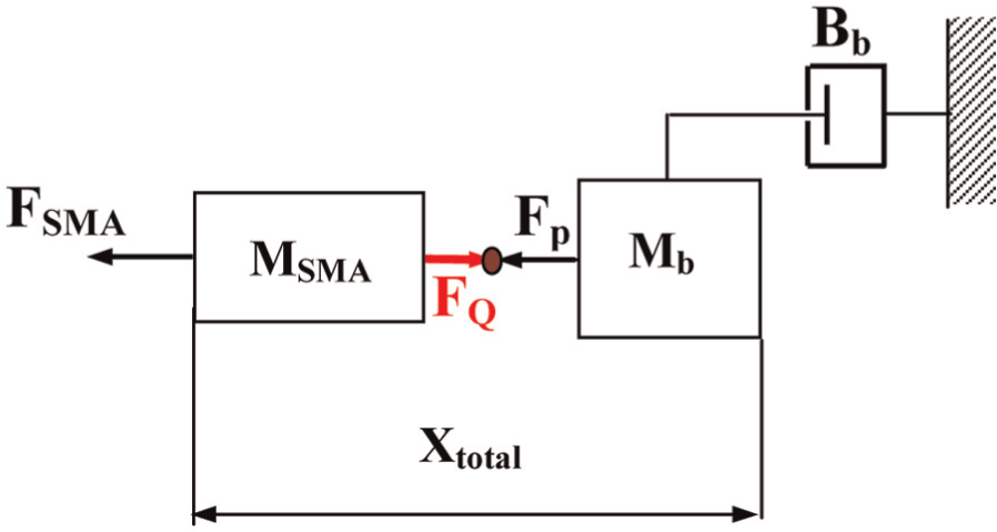
The above observation suggests the plausibility of applying a human muscle-like model to represent the motion of a class of agonistic–antagonistic SMA wire-based actuators such as the one shown in Figure 2. Based on the observed similarity between the human muscle motion and the SMA wire actuator motion, the schematic representation in Figure 2 can be modified according to the approach described in Wu et al. (1990) where authors model the human muscle motion. The modified schematic representation is shown in Figure 4.
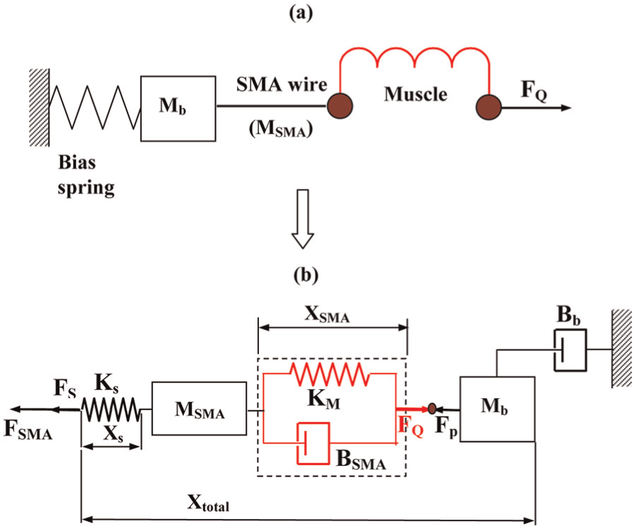
SMA actuator: (a) its “muscle” schematic representation and (b) its equivalent representation (adapted, based on Wu et al., 1990).
The modified schematic representation in Figure 4(a) represents the SMA actuator as a “muscle” (including the SMA wire with mass MSMA) attached to the bias spring through the payload Mb. The “muscle” is activated by the recovery force FQ. The recovery force is proportional to the displacement of the SMA wire due to the SME of the SMA material and is characterized by the amount of the SMA material transformed into austenite, that is, the austenite fraction
The corresponding equation of motion of the SMA wire actuator (without the payload system), schematically represented in Figure 4(b), can be written as
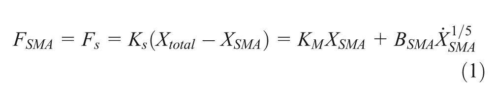
The equation of motion, equation (1), contains the nonlinear term
Solving equation (1) yields the total displacement of the SMA wire system
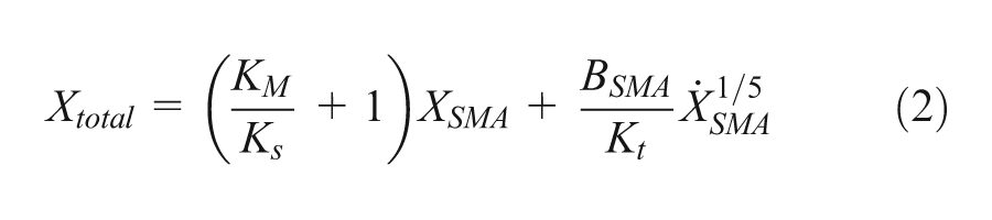
that can be alternatively schematically represented by the diagram shown in Figure 5, while the payload system can separately be schematically represented by the diagram in Figure 6.
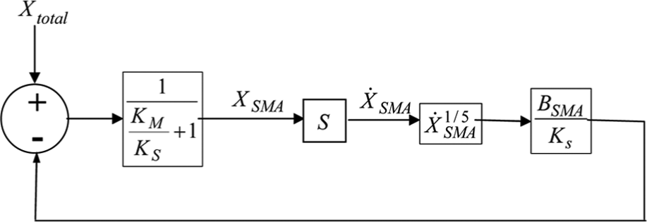
Schematic representation of equation (1).
Payload system (based on Wu et al., 1990).
The corresponding force balance equation for the payload system depicted in Figure 6 can be written as
where
where
where
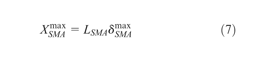
where LSMA is the total initial (unstretched) length of the SMA wire.
Combining equations (3) and (4), the equation of motion of the payload system becomes
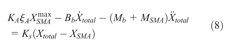
The equivalent schematic representation of equation (8) is shown in Figure 7.
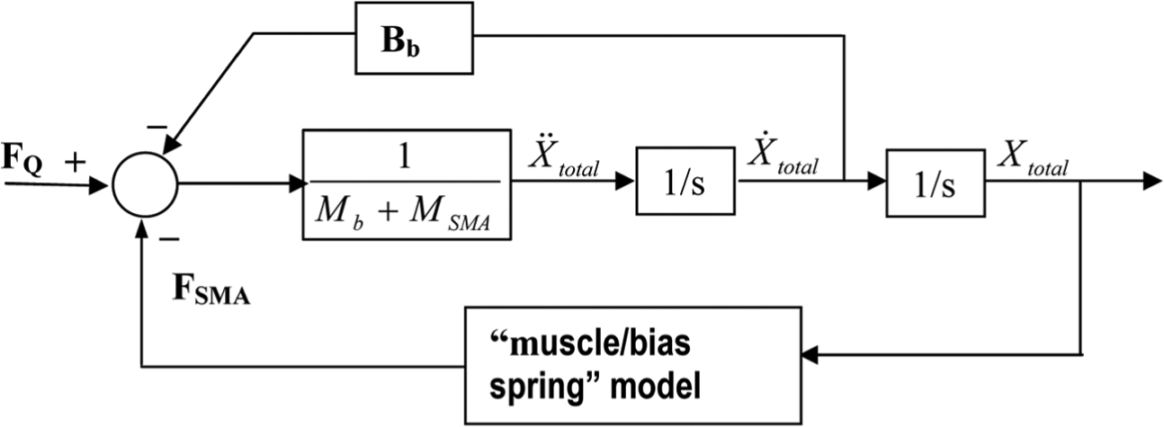
Equivalent schematic representation of the payload system.
Combining the force balance equations (8) and (1) according to Figures 6 and 7, the motion of the actuator can be described as follows
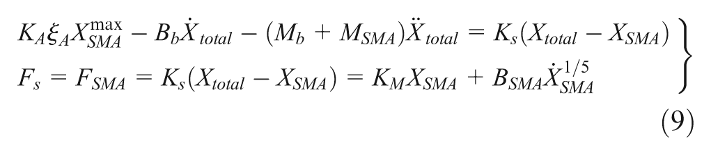
or schematically represented by combining, respectively, Figures 6 and 7 into the schematic representation in Figure 8.
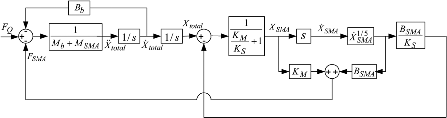
Equivalent schematic representation of the motion model of the SMA wire-based actuator.
The nonlinear behavior of the SMA actuator is represented by the term
It has been assumed in this model of motion that the SME recovery stress is significantly greater than the payload stress (e.g. externally applied stress or other). It is also assumed that the SME-induced stress is proportional to the austenite phase fraction, generated in the material during temperature-induced phase transformation (reverse transformation). That is, the phase state of the material heated above the Af temperature level, at which the complete (final) recovery of the SMA structure is achieved during the reverse transformation, corresponds to its pure (final) austenite state.
Based on the assumptions above, it can also be concluded that only the growth of austenite drives the SME-induced motion of the SMA actuator. Therefore, the presence of the martensite fraction during the reverse transformation is irrelevant in this case to the computation of the SME-induced stress (recovery force), since it does not affect the SME-driven motion of the actuator. In addition, the presence of any other stress (e.g. externally applied stress) is assumed negligible in comparison to the SME recovery stress.
The suggested model of motion does not account for hysteresis in SMA; therefore, the damping coefficient BSMA does not represent the material damping, but, rather, it represents the velocity-dependent damping, which is regularly used in conventional equations of motion. The difference between the conventional way to define the velocity-dependent damping (in an equation of motion) and the approach used in the current model lies in the fact that in this model, damping term is nonlinear, being
Determination of the damping coefficient (BSMA)
In order to be able to properly model the dynamic response of the NiTi SMA actuator, it is important to adequately describe the damping property of the system. The difficulty lies in the fact that due to the nonlinear properties of the NiTi material, the motion response of the NiTi SMA actuator cannot be modeled using a conventional differential equation of motion with constant coefficients, but it must be modeled by a non-nonlinear differential equation of motion with a nonlinear variable damping coefficient.
The damping coefficient BSMA represents an intrinsic physical property of the SMA wire material and characterizes the nonlinear dynamics of the motion developed by the actuator (see equation (9), term
To solve the differential equations of motion of the SMA actuator, it is necessary to obtain the value of the damping coefficient (BSMA) in equation (9). In principle, the damping coefficient could be determined by the use of existing approaches described earlier in this article. The difference between these approaches and the method to be suggested below is in the fact that the motion of the SMA actuator is governed by SME-driven recovery, and therefore, the known SME property of the material can be taken advantage of. To accomplish this, a combined analytical and experimental approach will be used. The analytical approach will allow the formulation of an expression for the damping coefficient, while experimental measurements of the SMA wire actuator’s step response will be utilized to estimate some of the parameters in the derived analytical expression for the damping coefficient. The intrinsic physical property of the SMA material of the actuator to develop its maximal SME-driven recovery displacement,
To derive an analytical expression for the damping coefficient BSMA, equation (1) is solved (integrated) with respect to the displacement XSMA. For the integration, it is assumed that the displacement is negligibly small, and therefore, the corresponding damping coefficient BSMA is assumed constant. After equation (1) is solved, it can be rewritten in terms of the damping coefficient as a function of the displacement, thus yielding the desired analytical expression.
It is possible to rewrite the equation of motion of the SMA actuator, equation (1), in terms of an assumed equivalent stiffness term of the SMA wire as follows
where
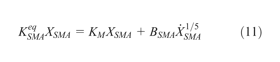
Equation (11) was formed after equating forces FSMA from equations (1) and (10). Here,
Rearranging equation (11) in the form
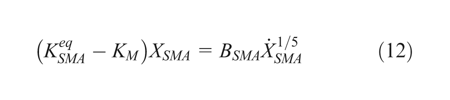
results in the following expression for
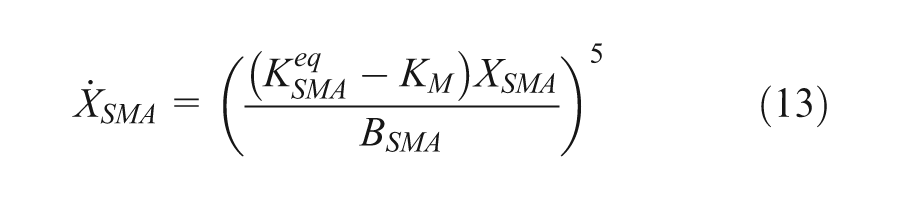
Differentiating equation (13), one can write
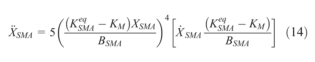
In accordance with Figures 5 and 7, equation (10) can also be written as
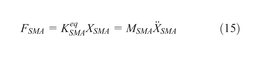
Rewriting equation (15) in the form

and using the variable XSMA from equation (16) into equation (14), it is possible to write
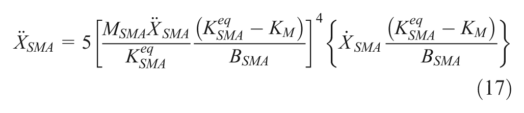
whose simplification gives
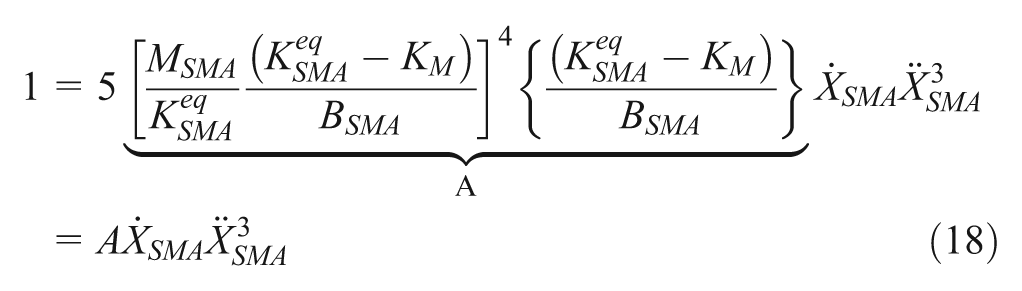
In order to solve equation (18), a change of variables is introduced as
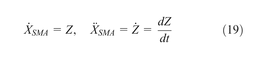
yielding
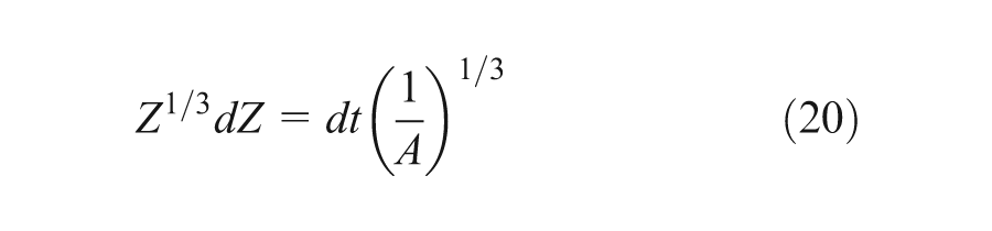
By integrating equation (20) by parts, one obtains
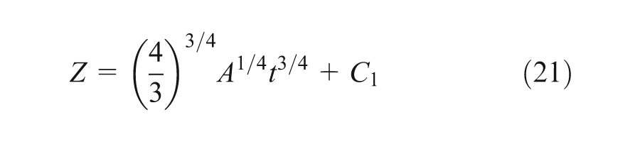
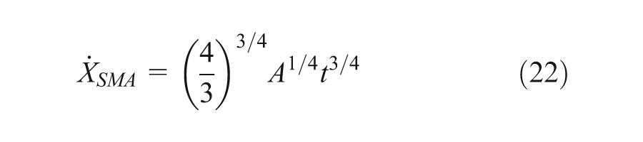
The initial condition Z = 0 (velocity of motion of the SMA wire = 0) at time t = 0 in equation (21) yields the integration constant C1 = 0. Therefore, the expression for
Integration by parts of equation (22) gives
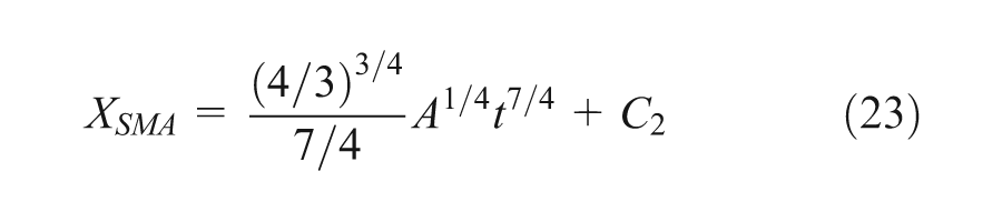
The integration constant C2 in equation (23) can be defined from the following initial conditions: XSMA = X0 (m) (initial position of the SMA wire actuator) at t = 0 s. Therefore, C2 = X0 (initial position of the SMA wire actuator). Using the constant C2 and coefficient A in equation (23), one can write
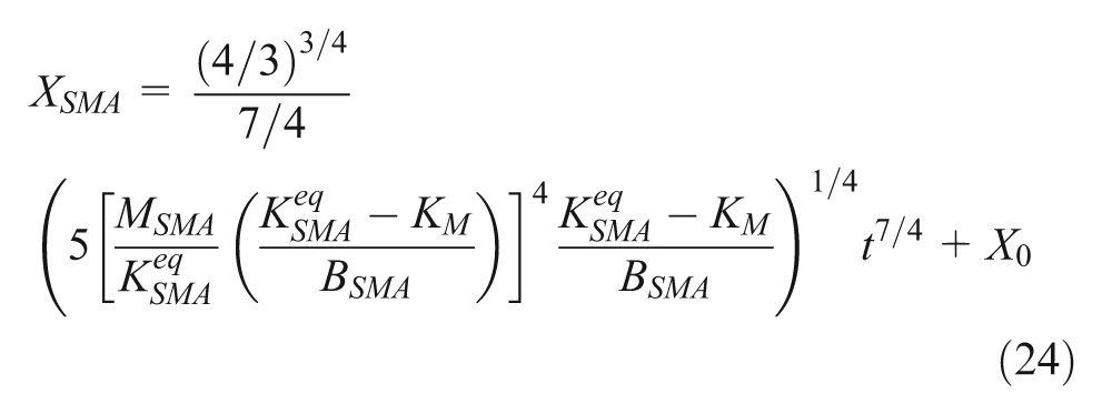
or
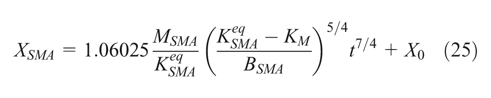
Therefore, the damping coefficient BSMA can be obtained from equation (25) as
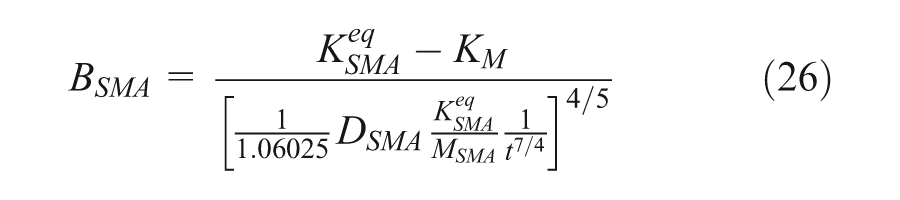
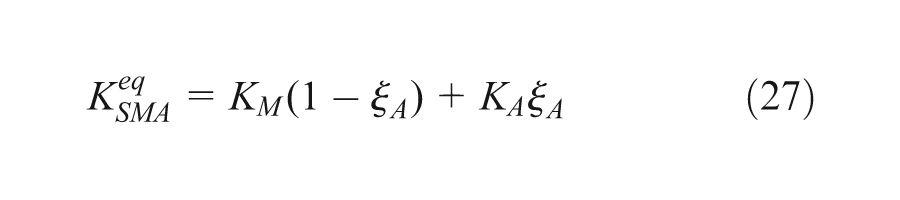
where DSMA = XSMA−X0 characterizes the relative displacement of the SMA wire (here X0 = 0 is the initial position of the wire). In equation (26), the equivalent stiffness of the SMA wire
This method of identification of the damping coefficient
The displacement
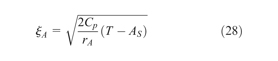
Equation (28) defines the austenite phase fraction,
Since the suggested model of motion is based only on the reverse temperature-induced phase transformation property of NiTi SMA, equation (28) is adequate and sufficient to use in the model. Equation (28) shows that the active actuation in the SMA actuator takes place only during heating of the actuator’s structure during the martensite-to-austenite phase change of the NiTi material. Another assumption we have used in the derivation of equation (28) mentioned in our work (Malukhin and Ehmann, 2012) was that the initial state of the NiTi SMA material is detwinned martensite and the boundary condition is that the SMA material temperature changes within the limits As < T≤Af.
In order to experimentally verify the suggested model of motion of the SMA wire-based actuator (system of equation (6)) and the expression for the damping coefficient (equation (26)), a series of step response experiments with the SMA wire-based actuator were conducted as described in the next section.
Experimental modeling of the motion of the SMA actuator
An experimental setup, representing a functional prototype of the SMA wire actuator, has been designed and built for verification purposes. The conducted step response experiments have been used to measure the contraction displacement of the SMA wire subject to a step heat load.
Experimental setup
The SMA wire actuator setup is shown in Figure 9. The actuator system consists of an SMA wire/bias spring system, payload system, and measurement and data acquisition (DAQ) system. The payload system includes the payload mass (Upper Block) and an air-bearing stage. The air-bearing stage is used because it allows for frictionless motion of the SMA wire and, therefore, has advantages in comparison to regular linear bearings in measurements of the dynamic response characteristics of the actuator.
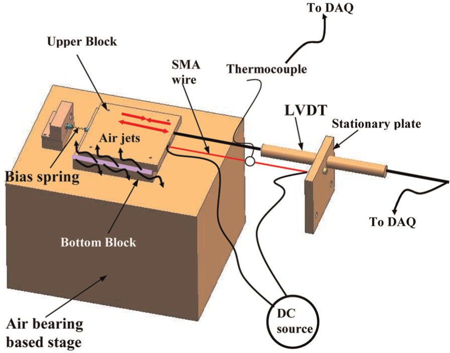
SMA wire-based actuator system.
The measurement and DAQ system consist of a linear variable differential transducer (LVDT), thermocouple, direct current (DC) source, and a DAQ card, controlled by LabVIEW software (see Table 1).
Specification of the experimental setup.
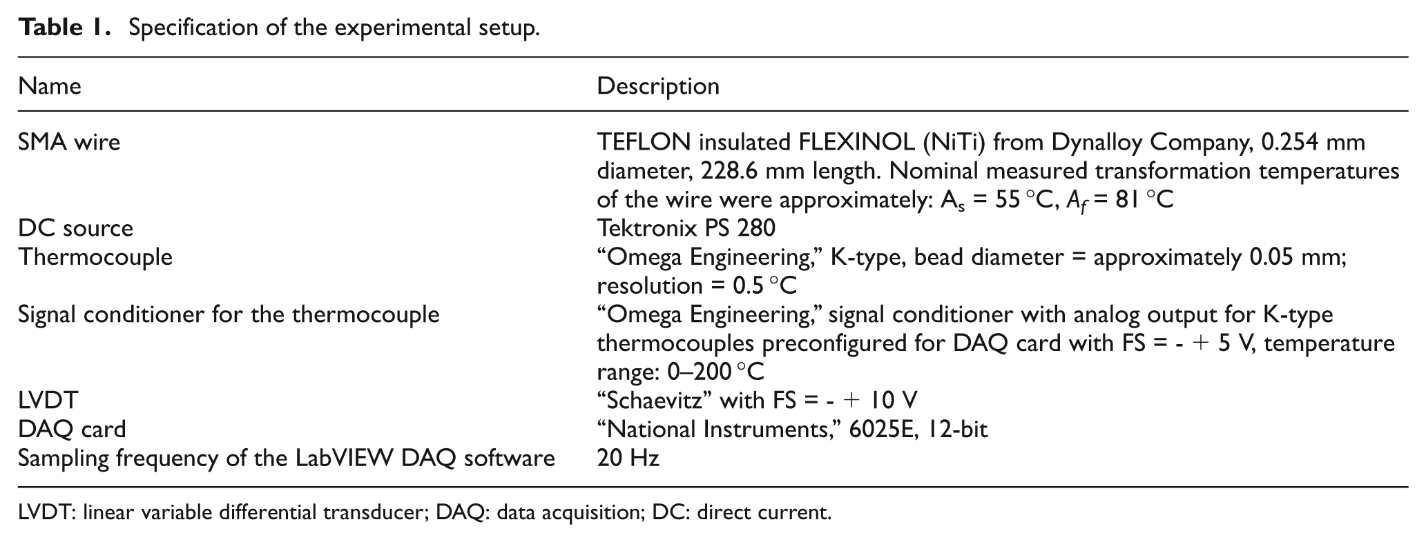
LVDT: linear variable differential transducer; DAQ: data acquisition; DC: direct current.
The SMA wire is connected to a stationary plate on one end and is attached to the moving payload mass (Upper Block) on the other end. The bias spring is attached to the payload mass such that it forms the agonist–antagonist layout of the SMA actuator system, as shown in Figure 9. The LVDT is mounted on the stationary plate such that its moving core is attached to the moving payload mass in parallel to the SMA wire. The LVDT is used to measure the displacements of the SMA wire. The LVDT output is connected to the DAQ card. The power supply is connected to both ends of the SMA wire to provide a resistive heat load to it. The thermocouple is attached to the SMA wire to measure its temperature. The thermocouple was attached to the SMA wire by means of a heat conducting glue. The thermocouple bead diameter was approximately 0.05 mm, which constitutes about 20% of the size of the SMA wire diameter that is well-accepted practice in temperature measurements methods. The resolution of the thermocouple (Table 1) is sufficient to properly capture the dynamics of the suggested SMA actuator model. In general, it is difficult to completely guarantee ideal heat sink conditions in experimental studies; however, in this study, the best possible heat sink conditions were provided. This fact can be proven by the good agreement of the step response experimental and theoretical results obtained from the motion model of the SMA actuator that will be shown later in this article. Output readings from the thermocouple are fed to a calibrated signal conditioner that is connected to the DAQ card. The DAQ card is controlled by the DAQ program written in the LabVIEW environment. The program collects the LVDT and thermocouple readings from the DAQ, converts them to calibrated values of displacements and temperatures by means of calibration equations, and records them as functions of time.
The experimental setup (Figure 9) has all the key components of the equivalent representation of the SMA actuator system (Figure 4) based on the corresponding equivalent representation of the human muscle motion model used by Wu et al. (1990). The aim of this study was not to repeat the same experimental conditions employed by Wu et al. (1990), but only use the conceptual approach and similarity in adapting their human muscle motion model to the SMA actuator motion model.
Experimental procedure and results
Experimental tests aimed at studying the step response behavior of the SMA wire actuator system due to a heat load were conducted according to the following experimental procedure:
Initially, the SMA wire is non-stretched and is in its martensite condition.
The SMA wire is pre-stretched at room temperature, which is around its martensite finish temperature. In this state, detwinned martensite transforms into twinned martensite pseudo-plastically; thus, the SMA wire retains its pre-stretched length after the external force is removed at room temperature.
Resistive heating is applied to the wire through the application of an electrical current to it in a step-like way.
Upon heating the wire above its austenite start temperature, it contracts back to its non-stretched position due to the SME-driven motion. This process is characterized by the transformation of the twinned martensite to austenite. During the contraction motion of the wire, its temperature and displacement are measured by the LVDT and thermocouple and recorded by the LabVIEW program.
Several step response experiments were conducted based on the experimental procedure described above. Sample experimental results from one of the experiments are shown in Figure 10. Heat load was applied to the pre-stretched SMA wire, heating it gradually from room temperature at about 20 °C up to a maximal temperature at about 55 °C. The heating was done in 14 °C–4 °C temperature increments (Figure 10(b)). The total measured displacement of the SMA wire during its contraction was about 8.8 mm (Figure 10(a)). The values of the intermediate displacements ranged from 0.5 to 2 mm. The experimental results shown in Figure 9 can be used to evaluate the expression for the nonlinear damping coefficient in equation (26) and to verify the model of motion of the SMA wire actuator.
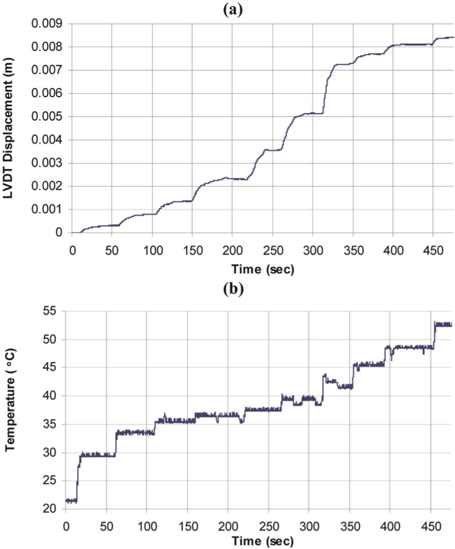
Step response of the SMA wire actuator: (a) displacement of the wire and (b) temperature of the wire.
Although several experiments with similar working conditions were performed in this study, only one of them is presented in this article, since all the experiments produced similar results. One of the working conditions was to maintain approximately adiabatic conditions between the SMA wire and the environment—the so-called ideal heat sink conditions. Therefore, it was not important to report the DC voltage, assuming that nearly adiabatic conditions were achieved by means of thermally insulating the SMA wire. The SMA wire was assumed to be in thermal equilibrium, which was also one of the assumptions made for the formulation of the theoretical model of motion. An example of the verification of the damping coefficient and the model of motion of the SMA wire actuator based on the experimental data above is given in the following.
Experimental evaluation of the damping coefficient
The evaluation is based on the step response experiments where the SMA wire develops its maximal SME-driven displacement DSMA upon application of a heat load. The measured maximal displacement, DSMA, versus time, t, can be obtained from step response experiments similar to the one described above, but conducted under the maximal recovery conditions—that is, the SMA wire is given a maximal pre-strain, which is recovered in one displacement step, thus developing a maximal recovery displacement.
For example, experimental data from a step response experiment with the maximal recovery conditions give
Properties and geometrical data of the SMA NiTi wire.
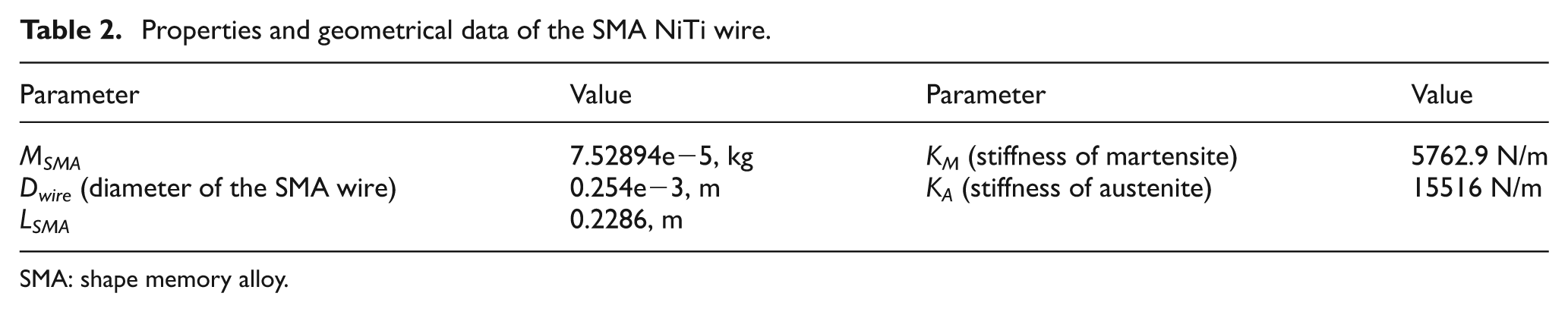
SMA: shape memory alloy.
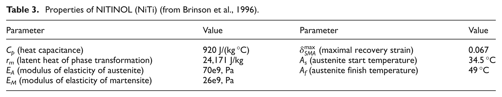
Properties of NITINOL (NiTi) (from Brinson et al., 1996).
The obtained value of the damping coefficient
Verification of the model of the SMA wire-based actuator
The Simulink/MATLAB environment was used to simulate the step response of the SMA wire actuator based on the model described by equation (6) (as shown in Figure 8), using the experimentally evaluated damping coefficient
The generalized schematic representation of the model of motion used in the Simulink model is shown in Figure 11. The measured temperature (Figure 10) of the SMA wire, TSMA, serves as the input to the model of motion. The output of the model is the displacement, DSMA, of the SMA wire.
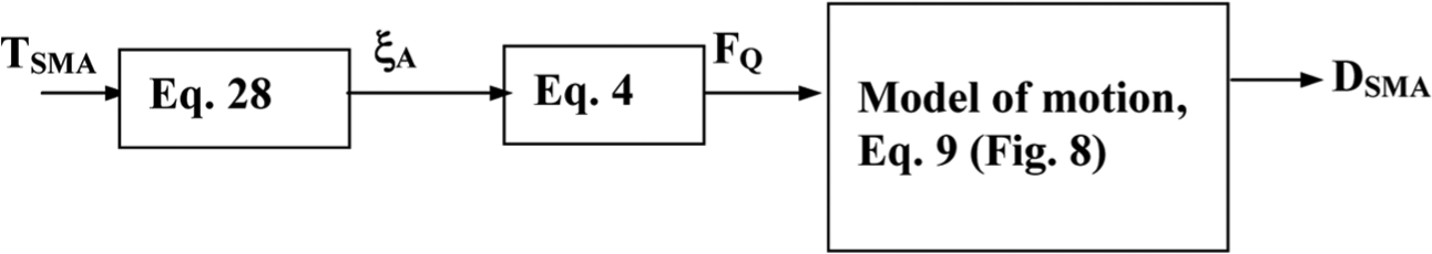
Schematic representation of the Simulink model.
Several numerical simulations/examples, aimed at the verification of the model of motion of the SMA actuator, were conducted. In each simulation run, the displacement (DSMA) evolution of the SMA wire subject to a heat load (represented by the input temperature TSMA taken from an experiment) was computed. The numerically modeled step response of the SMA wire was compared to the experimentally measured step response. An example of such a comparison of a simulation and experiment is shown in Figure 12. The input to the theoretical model was the averaged measured temperature (shown as solid line in Figure 12(a)).
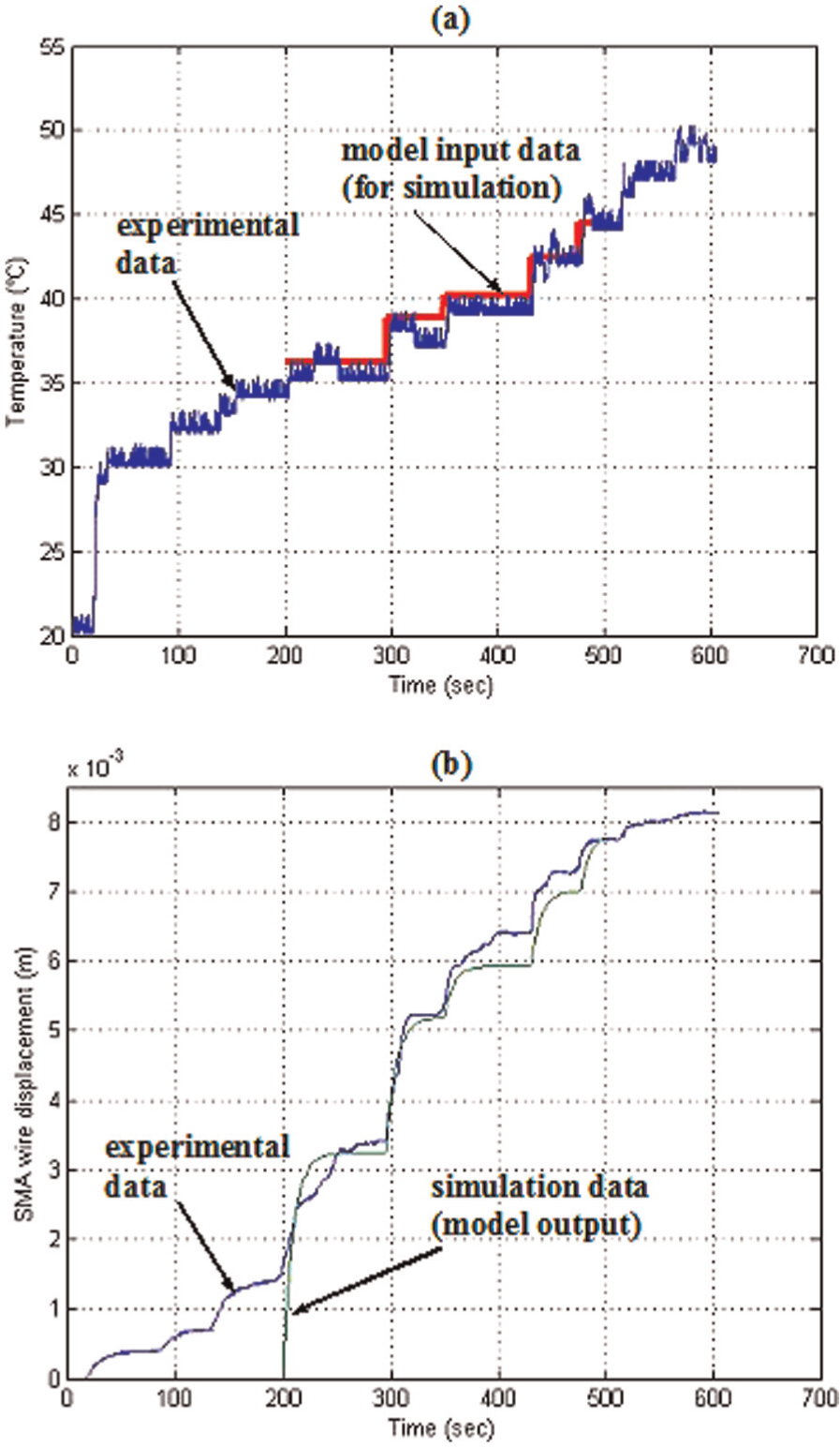
Simulation of the motion of the actuator and its experimental verification: (a) temperature of the SMA wire, TSMA, and (b) output relative displacement of the SMA wire actuator, DSMA.
The suggested model of motion of the SMA wire actuator agrees well with the experimental results. The discrepancy between the experimental and theoretical simulation data plots in the time range of 0–200 s in Figure 12(b) is related to the fact that the suggested theoretical model of motion of the SMA actuator is valid only in the temperature range where the austenite phase transformation takes place, that is, between temperature As and Af. This temperature range serves as the boundary conditions of the model. It follows from the fact that the experimentally measured As temperature has been achieved at 200 s time point as seen in Figure 12(a) (“experimental data” plot). Therefore, this time point has been assumed to be the start of the austenite phase transformation in the SMA wire and, therefore, is considered as the starting point of the SMA wire contraction. Based on the “experimental data” plot (Figure 12(a)), the “input data” plot has been computed (Figure 12(a)), representing the average temperature of the “experimental data.” The “input data” plot served as the input to the mathematical model of the temperature-induced phase-transformation-driven motion model (shown in Figure 11). The output results of the SMA actuator motion model (the DSMA parameter in the model in Figure 11) are shown as the “simulation data” plot in Figure 12(b).
By observing the experimentally measured SMA wire actuator displacement and numerically simulated model displacement in Figure 12(b), it can be concluded that the combination of the model of motion and the damping coefficient model offers a good estimate of the performance of the SMA wire actuator due to the good agreement between the experimental step response data and the numerically simulated step response data, as shown in Figure 12(b). A series of similar step response experiments in connection with the corresponding theoretical simulations of the step responses of motion of the SMA wire actuator has shown a similar good agreement between measurements and simulations.
The qualitative resemblance (fast and slow response regions) between the behavior of the human muscle contraction and the SMA actuator motion was used only as an initial tool to identify the proper motion model, which, in this case, was the human muscle motion model. The quantitative proof that the muscle motion model can be used as the basis for the description of the SMA actuator motion model is confirmed by the result outcomes, as shown in Figure 12(b).
As Figure 12(b) shows that the nonlinear motion model of the human muscle in combination with the SMA kinetics model gives an excellent agreement with the experimental data derived from the step response of the SMA actuator motion. The excellent agreement between the experimental and computed displacement data in Figure 12(b) proves that the averaging technique used in order to obtain the temperature “input data” (Figure 12(a)), as described above, is sufficient and acceptable. Therefore, this experimental verification can be used to complete the reasoning behind the choice of the motion model.
The suggested motion model uses the specific nonlinear damping coefficient. Therefore, it was necessary to derive the corresponding model of the nonlinear damping for this particular type of SMA actuator. The nonlinear damping is the key component of the motion model, and it properly describes the dynamics of the SMA actuator’s motion in the sense of the approach used by the authors in Wu et al. (1990). The suggested motion model is simpler and, therefore, more robust than the other existing SMA motion models, since it does not use any approximation techniques that other motion models are based on, such as, for example, in Elahinia and Ashrafiuon (2002). The reason why the suggested motion model describes only temperature-induced SME motion and does not describe the hysteresis of the SMAs is the fact that, first, only the temperature-induced phase transformation in SMAs generates the SME-driven motion of the actuator, and therefore, it was important to be able to properly model this part of the SMA actuator’s motion. Second, the experimental verification of the motion model can also, in this case, be conducted in a much simpler way. Thus, this motion model could serve as an ideal motion model that can be expanded in the future to incorporate the hysteresis of SMAs.
The observed discrepancy between the theoretical and experimental data in Figure 12(b) can be related to two factors: (1) in the time range from 0 to 200 s, no simulation was performed since it was assumed that the motion model is valid only within the range of the temperature-induced reverse phase transformation, that is, between As and Af. Since experimental data show that the As temperature of the SMA wire was achieved at the time point corresponding to 200 s, it was assumed that the wire starts contracting at this time point; hence, the theoretical simulation of the SMA wire contraction motion started at 200 s; (2) the slight deviations in the time range between 200 and 500 s are related to experimental limitations associated with maintaining ideal heat sink conditions for the SMA wire.
There are two major potential sources of errors in the current experimental setup that could affect the SMA actuator response: (1) heat sink conditions and (2) friction conditions. The heat sink conditions were improved greatly by thermally insulating the SMA wire, while the friction was almost completely avoided by means of using the air-bearing stage.
In spite of the fact that the ultimate goal of this study was to develop a motion control model of the monolithic actuator shown in Figure 1, a motion model of its equivalent in the form of the SMA wire-based actuator was developed. Results in Figure 12 show the open-loop control model of the SMA wire actuator. The suggested method of deriving the equations of motion for the SMA wire actuator system and the respective damping coefficient was easier to implement and, afterward, experimentally verify, rather than developing the corresponding model of motion for the SMA spring actuator system. It was the most efficient way to describe the basic elements of the suggested mathematical model of motion of a general SMA actuator system. The obtained results will facilitate the development of models for other actuator configurations as well and form the basis for the formulation of closed-loop control models of the monolithic SMA actuators.
Conclusion
A description of a model of motion of an SMA actuator powered by a model of nonlinear damping of the actuator was developed and described in this article. A method for the determination of the damping coefficient of the SMA actuator system was described as well. The damping coefficient was evaluated and used in the model of motion as one of the input parameters. The comparison of experimental results and numerical results obtained from the experimental and theoretical models of the SMA actuator has shown a good agreement. Therefore, the suggested model of motion and the method for the determination of the damping coefficient were proven to be reliable and robust and can be used for the prediction of the SME-driven motion of the SMA actuators with nonlinear damping properties. The motion model is valid only in the temperature range that corresponds to the temperature-induced phase transformation in the SMA material.
The suggested SMA wire actuator model is derived based on several novel concepts that were introduced for the first time in this work, namely, the concept of monolithic actuator (a “smart” structure with no moving parts and no assembly), human muscle motion concept applied to the SMA wire, and others. Therefore, it was easier to initially develop and experimentally verify the suggested SMA wire-based model to prove the validity of these concepts.
The SMA actuator represents a complex nonlinear system, whose motion should be respectively controlled by nonlinear controllers, such as adaptive fuzzy control methods, variable structure control methods, or similar. Sometimes, these methods require complex system identification procedures that are eventually based on certain approximation techniques. The motivation for this research was to develop a nonlinear motion and control model of this type of SMA actuators (agonist–antagonist) that does not use an approximation method, such that the suggested model can be based on the intrinsic fundamental properties of the SMA material to develop the SME-driven motion during the temperature-induced phase transformation in SMAs. The advantage of the suggested motion model is that it is, first of all, simpler than the other SMA actuator motion models and it is more robust, since it is based on the fundamental physics behind the phase transformation.
Currently, this model can be used as a precisely experimentally verified auxiliary tool in the existing SMA actuator motion control models that describe only the SME recovery motion of an SMA wire actuator. In future studies, a similar logic of description of the model of motion of the SMA wire-based actuator can be applied to the SMA spring-based actuators. That is, similar equations of motion can be written for the monolithic SMA actuator system shown in Figure 1, where the actuating elements would be the accordion springs. Afterward, the damping coefficient can be derived for the SMA springs based on the method suggested in this study for SMA wires. Finally, similar step response experiments and numerical step response simulations can be conducted in order to verify the motion model of the monolithic SMA actuator and to validate the respective damping coefficient expressions.
Footnotes
Acknowledgements
The authors are thankful to Professor Brinson (Department of Mechanical Engineering, Northwestern University, Evanston, IL) for her valuable comments and suggestions.
Declaration of conflicting interests
The authors declared no potential conflicts of interest with respect to the research, authorship, and/or publication of this article.
Funding
This study was financially supported by the National Science Foundation (USA) (grant #DMI-0400316).