






Abstract
This article presents a sensorless resistive-based control method to control shape memory alloy wire actuators to be used in the development of a laparoscopic surgical locking system. Shape memory alloy wire electrical resistance is measured to control the martensite phase fraction of shape memory alloy wire. The martensite phase fraction is calculated based on mathematical heating model, resistance models, and the measured resistance. Experiments are conducted to evaluate the validity and performance of the method in the control of the locking system angle. The results show that the sensorless resistive-based control method accurately controls the wire without using any position sensors, resulting in the lower cost, size, and weight of the system. The results show very small steady-state errors, verifying the practicability of this method. The sensorless resistive-based control method has the potential to be used in many applications in which cost and space are limited and the use of an external sensor is impossible or costly.
Introduction
Shape memory alloy (SMA) actuators are metallic materials that can regain their predetermined shapes by changing temperature. These actuators have been used in many applications, such as shape control of aircraft wings, micro-robot manipulation, robotics, micro-system precision control, and medical applications (Fu et al., 2004; Hirose et al., 1989; Huang et al., 2013; Kode and Cavusoglu, 2007; Kuribayashi, 2000; Madden et al., 2004; Moallem and Lu, 2005; Payandeh et al., 2001; Pfeiffer et al., 1999; Shahinpoor and Wang, 1994; Tu et al., 1998).
Recently, we have proposed an automatic suturing-ligation laparoscopic (LigLAP) method as an alternative method to stapling for surgical occlusion process (Yousefian et al., 2013). In this method, a locking mechanism is required to complete the ligation procedure. In addition, the actuator size in laparoscopic surgery devices is critical due to the small space available in laparoscopic surgeries. With this in mind, our attention is directed to use an SMA-based locking mechanism and the control of the SMA actuator. A complete and recent review of biomedical applications using SMA actuators is provided by Huang et al. (2013). The required background for laparoscopic surgery and the ligation method are presented in section “Automatic ligation in laparoscopic surgery.”
The control of SMAs is important and challenging due to their highly nonlinear behavior and hysteresis. Many methods have been presented in the literature (Asua et al., 2010; Kha and Ahn, 2006; Ma et al., 2004; Moallem and Tabrizi, 2009; Song, 2002; Troisfontaine et al., 1998) to control SMA actuators using external sensors. However, a few studies have used the electrical resistance of SMA actuators to control the position of SMA wires. In these studies, due to the highly nonlinear behavior of SMAs, non-model-based control methods, for example, neural networks, have been employed to map the displacement and electrical resistance of SMA actuators (Asua et al., 2010; Ma et al., 2004). The details of these methods are presented in section “Control of SMA actuators.”
The SMA ability to regain its predetermined shape is due to the reversible crystalline phase transformation. The phase transformation occurs because of the temperature and stress changes in the material structure. SMAs have two certain stable crystalline phases: austenite is a high-temperature phase and martensite is a low-temperature phase. When a material that shows this effect is deformed at low temperature, it will regain its original shape before deformation when heat input is provided. The characteristics of SMA result in significant strain recovery during the phase transformation.
In this article, we present a sensorless control method (sensorless resistive-based control (SRBC)) of an SMA-based locking mechanism based on resistive and heating models of SMA wires. The main objective is to control the position of the SMA-based locking mechanism, utilizing actual electrical resistance. Due to the linear relation of the strain of SMA wires and the martensite phase fraction (ξM), ξM is used as feedback in the position control of the SMA actuators. ξM is 1 for pure martensite and 0 for pure austenite phase (increasing the temperature decreases the ξM from 1 to 0). In this method, ξM is calculated based on actual electrical resistance, temperature, and stress of the SMA wire. The position of the SMA wire is calculated using experimental data gathering of position-martensite phase fraction. The details of SRBC method are presented in section “SRBC.” Several experiments are conducted to identify the required parameters of the resistive model, including temperature dependence of martensite and austenite and stress dependence of martensite and austenite. In addition, the validity and performance of the method are evaluated through an experimental verification procedure using a prototyped SMA-based locking mechanism. The details of the experimental setup and procedure as well as results and discussions are illustrated in section “Experimental verification.” The conclusion and future work are presented in section “Conclusion and future work.”
Control of SMA actuators
Modeling and control methods of SMA actuators have been extensively investigated in the literature. However, complex thermal–electrical–mechanical dynamics of SMA actuators and their temperature dependency make their control challenging and, of course, difficult. For position control, there are two types of control algorithms (Ma et al., 2004): (a) employing a reverse dynamic model to compensate for the nonlinearity and hysteresis characteristics and (b) incorporating a feedback loop. In the feedback loop, feedback signal in the control algorithms may include temperature, position, and/or electrical resistance of SMA actuators. Troisfontaine et al. (1998) have studied the feedback control of SMA-based micro-actuators using temperature. Also, position feedback has been used in several control applications with various position sensors. For instances, a potentiometer (Kha and Ahn, 2006), a linear variable differential transformer (LVDT; Song, 2002), and an encoder (Moallem and Tabrizi, 2009) have been used as position sensors. However, using a position sensor increases the cost, weight, and overall size. We have developed the SRBC method to avoid using any external sensors to control the SMA-based locking mechanism.
The electrical resistance of SMA actuators is not constant during the process of changing the temperature and can be used in the control loop. The resistance is one of the 23 properties of SMAs that may be changed due to phase transformation (Harrison, 1990). Although the relationship between SMA actuator strain and the electrical resistance is highly nonlinear, this relationship can be used to control SMA actuators.
Ma et al. (2004) and Asua et al. (2010) have presented sensorless methods to control SMA actuators and obtain an accurate and stable position control. To avoid using position sensors, electrical resistance of the SMA actuator has been utilized as feedback. The relationship between strain and electrical resistance of the actuator has been modeled using a neural network to predict the position of the SMA actuator. Neither studies have been used a mathematical model of SMA actuators. Proportional–derivative (PD; Ma et al., 2004) and proportional–integral–derivative (PID; Asua et al., 2010) controllers have been employed in the closed-loop control. Both studies experimentally evaluated their methods and results show accurate control of SMA positions. Asua et al. (2010) have also used a first-order equation for the contraction curve and have reported better results for neural network (the position error about 70 µm). Although these methods can control the position of the SMA wire without any external sensor, they use a non-model-based method to model the relationship between resistance and displacement. In addition, changing stress on the SMA wire is not predicted. This may affect the design and development of control strategies. In the method presented in this article, there is no need to use a non-model-based method due to the incorporation of resistance and heating models. In addition, stress is involved in the SRBC method as an input variable. Thus, stress can be changed without significant changes in our control strategy.
Kim et al. (2013) have also addressed these issues in their study on the position estimation of an SMA coil spring actuator using inductance. Displacement has been estimated under various stresses using inductance of an SMA coil spring. The inductance–displacement and resistance–displacement curves are compared, and the results show that the resistance–displacement is highly affected with stress, while only a small variation is observed for the inductance. Their experimental results show reasonable accuracy for displacement estimation of the SMA coil spring. However, this method can only be used for the SMA coil springs and is not applicable to control of SMA wires.
Automatic ligation in laparoscopic surgery
Laparoscopic or minimally invasive surgeries (MIS) are well known and preferred in comparison to open surgeries. These surgeries allow surgeons to complete surgery operations using laparoscopic surgical devices through small incisions, avoiding undue loss of blood, and eschew manipulation of tissues. Hence, the body’s response to surgery is with a reduced immune activation and catabolism (Heald et al., 1982; Kapiteijn et al., 1998). Laparoscopic surgery and the immune response have been reviewed by Vittimberga et al. (1998), and it has been concluded that the body’s response to laparoscopic surgery is very low. There are several advantages for MIS, such as shorter hospital stays and recovery periods, less scarring, less injury to tissue, more postoperative comfort, and less postoperative pain (Fuchs, 2002; Johansson, 2003; Tanović and Mesihović, 2003; Yousefian et al., 2013). Therefore, the use of laparoscopic surgeries has increased and is preferred in possible operations. For instance, in surgeries such as cholecystectomy, kidney surgery, and resection of rectal cancer, in which it is necessary to occlude vessels and ducts, the laparoscopic versions of these surgeries are the procedures of choice. Laparoscopic cholecystectomy has replaced open cholecystectomy since it was first reported in 1987 (Gollan et al., 1993) and is one of the most frequently performed laparoscopic operations (Bencini et al., 2003; Champault et al., 1996).
Currently, laparoscopic stapling devices are frequently used as a method of duct closure and vessel occlusion in these surgeries (Golash, 2008; Yeh et al., 2004). Although stapling devices are commonly used for closure of ducts and/or vessels, several complications and problems are reported. Technical failures and dangers of stapling devices are possible when the staples are not closed securely (Belgaumkar et al., 2009). In addition, bile leak is a known postoperative problem that could be caused by dislodgment and migration of the clips, as well as bile duct necrosis (Golash, 2008; Medina, 2005; Ng et al., 1999; Saha, 2000). Moreover, a relatively large space behind the duct and/or vessel is required when using stapling devices. Other problems include vascular and duct injury, bleeding from the liver bed, and biliary leak (Bezzi et al., 1995; Jones and Soper, 1996; Shamiyeh and Wayand, 2004). Furthermore, in some cases—for example, in the presence of chronic inflammation—using stapling devices is difficult and dangerous.
Recently, we have proposed an automatic suturing-LigLAP method as an alternative for occlusion process, using a double-layer suture to occlude vessels and ducts. It is required to hold the suture in order to complete the LigLAP procedure. In addition, the actuator size in laparoscopic surgery devices is critical due to the small space available in laparoscopic surgeries. With this in mind, we have designed, prototyped, and experimentally evaluated an SMA-based locking mechanism to hold the suture in the LigLAP process (Yousefian et al., 2013).
SRBC
This section presents the details of the SRBC as a sensorless control method for the SMA-based locking mechanism. First, we generally describe the method, and then the models and blocks are presented in details.
In the SRBC method, the heating and resistive models of the SMA wires are employed to calculate the martensite phase fraction, using the actual electrical resistance, enabling us to control the wire without using any external sensors. One advantage is that neural network or other non-model-based methods are not being used to model the relationship between the martensite phase fraction and the position of the SMA wire due to the fact that martensite phase fraction has a linear relationship with strain. This will extend the scope of SMA wires sensorless control to employ model-based control strategies in addition to non-model-based algorithms. Another advantage of the SRBC method is that it can be used with various stresses on the SMA wire using the mathematical relationship between the martensite phase fraction and stress. Resistance of SMA wires is a function of martensite phase fraction, which itself depends on temperature and stress of SMA wires (Kim et al., 2013; Schiedeck and Mojrzisch, 2011). Since the SRBC uses martensite phase fraction, it can control the SMA wire under various stresses.
The block diagram of the control system is shown in Figure 1. Output of the θ−ξM transformation block in Figure 1 is the desired martensite phase fraction (ξM) based on the desired angle (θ). ξM is calculated using the measured electrical resistance (Rt) and computed resistance functions (RM and RA), which are detailed in section “Resistance model.” The control scheme is designed based on the heating and resistance models. A proportional–integral (PI) controller is used to minimize the martensite phase fraction error (eξ). Input current is sent to the SMA wire via the power supply. The current is calculated based on the input power command and the SMA wire voltage. In addition, the actual resistance of the SMA wire is measured using the SMA wire voltage and the applied current. The heating and resistance models of SMA wires are presented in the following sections.
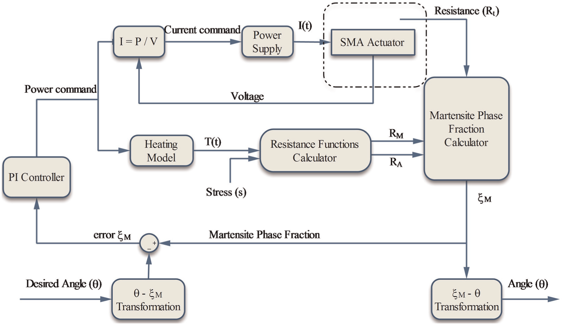
Overview of the control system block diagram. Electrical current is applied to the SMA actuator based on the input power, using a programmable power supply. In addition, temperature is computed using the temperature model. Resistance functions (RM and RA) are calculated with the temperature and stress inputs. Martensite phase fraction is the output of the system, obtained from resistance model using calculated RM and RA, and actual electrical resistance. A PI controller is employed to control martensite phase fraction relevant to the desired angle.
Resistance model
In this section, we present the background and the details of the SMA wire resistance model. The model includes the Resistance Functions Calculator and Martensite Phase Fraction Calculator blocks in Figure 1.
According to the literature, Ikuta et al. (1988) have studied the resistance behavior of SMAs and designed a position control system using resistance feedback. It has been reported that the SMA wire has higher electrical resistance in martensite and lower in austenite. However, Novák et al. (2008) found that the resistance behavior of SMA wires is more complicated than the model reported by Ikuta et al. (1988). Increasing wire stress results in higher electrical resistance as well as increasing the martensite start temperature, martensite finish temperature, austenite start temperature, and austenite finish temperature. In addition, the electrical resistance linearly changes with temperature in the pure martensite and austenite phases. Novák et al. (2008) presented a resistance model for SMA actuators, where the specific resistivity of SMA wire is a function of specific resistivity of austenite, martensite, and R-phase with weights of austenite phase fraction, martensite phase fraction, and R-phase fraction, respectively. Song et al. (2011) have modified the model presented by Novák et al. (2008). In the modified model, the overall electrical resistance is a function of the electrical resistances of martensite and austenite. The effect of R-phase is negligible and eliminated to simplify the model. The modified resistance model is given by


where RA and RM are austenite resistance function and martensite resistance function, respectively; R0A and R0M are the nominal wire resistances of austenite and martensite at T0A and T0M temperatures, respectively; T is the temperature of the SMA wire; σ is the stress; and
The SRBC method measures the total resistance (

The temperature and stress dependence of the resistance functions of austenite and martensite are linear in equations (2) and (3).
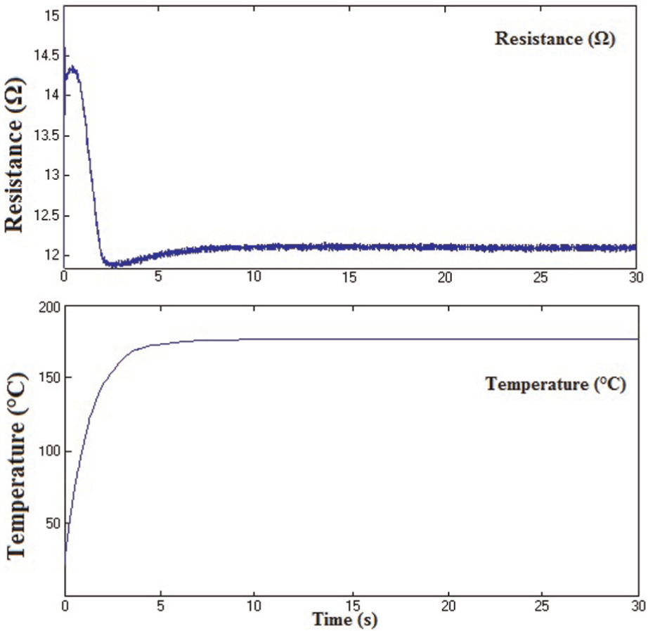
Resistance and temperature of the SMA wire under 234.076 MPa stress. By raising the temperature, the electrical resistance increases in the beginning, then decreases, and finally increases again, but with a smaller slope than the beginning.
The temperature dependence of the resistance functions of austenite and martensite (
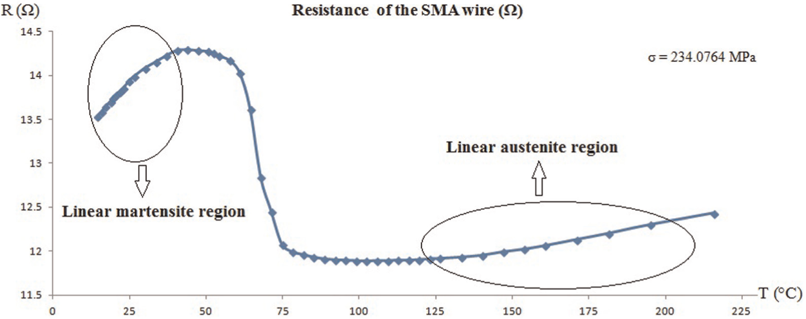
Resistance of the SMA wire at different temperatures. The resistance of the SMA wire increases almost linearly and reaches the maximum amount in the linear martensite region, and then decreases to the minimum amount. Furthermore, it slowly rises in the linear austenite region.
Linear temperature and stress dependence of resistance functions of austenite and martensite.

To find the stress dependence of the resistance functions of austenite and martensite (
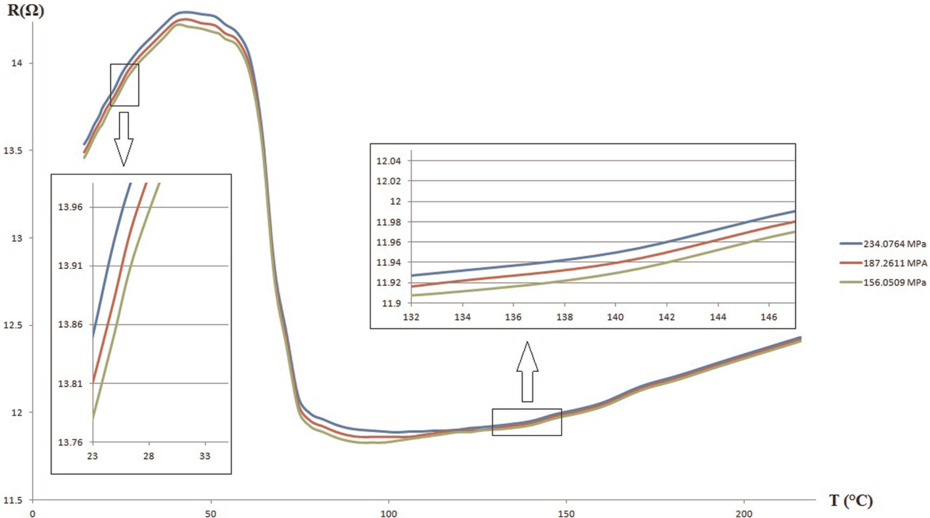
Resistance of the SMA wire for three runs of the experiment under different stresses. At the same temperature, larger stress causes the larger resistance of the SMA wire. The stress dependence of resistance functions is calculated by comparison of the SMA wire resistance curves for various stresses.
As shown in Figure 4, increasing the stress causes the increase in the resistance of the SMA wire and shifts the resistance curve upward as well as changing the temperature at which the transformation temperatures occur.
Heating model
In order to heat the SMA and increase its temperature quickly, the electric current is used based on Joule heating (equation (4)), which is also known as resistive heating. According to the literature, Joule heating is a convenient and practical heating method for small-size SMA wires (Sun et al., 2012). The effect of size is also critical (An et al., 2008). Therefore, the exact size of the SMA wire is included in the heating model. In addition, the nonuniform distribution of temperature using joule heating may be a problem in several applications (Huang, 2005); however, this effect is negligible in our application

Heating model block in Figure 1 calculates the SMA wire temperature using input power. In the heating model, the temperature of the SMA wire is a function of heat transfer. The heat transfer equation that relates the input power, equation (4), to the wire temperature is presented in equation (5) (Madill and Wang, 1998)

where ρ is the material density, c is the specific heat of the wire, V is the wire volume, T is the wire temperature, P is the input power, h is the convection heat transfer coefficient, A is the wire surface area, T∞ is the ambient temperature, and t is the time.
Conduction is ignored due to the assumption that the temperature is constant in the thin wire. In addition, the radiation is negligible in comparison to convection at the operating temperature. The cooling process is slow and can be implemented by natural air convection, or using appropriate cooling fluids or forced air convection to have a faster cooling. The total convection heat transfer coefficient (h) for a long horizontal cylinder, for example, SMA wires, is the sum of natural convection heat transfer coefficient (hn) and forced convection heat transfer coefficient (hf), as seen in equation (6). The forced convection (hf) is due to the airflow in the environment around the SMA wire

The natural convection heat transfer coefficient is calculated based on equation (7) (Lavine et al., 2011)

where k is the conductivity of air, D is the diameter of the cylinder, and NuD is the Nusselt number.
Morgan (1975) has suggested a power form expression for the Nusselt number as follows

where C and n are constants for a broad range of Rayleigh number (RaD). The constant numbers are shown in Table 2. In addition, RaD is calculated by equation (9)

Constant numbers of equation (8) for various ranges of RaD (Morgan, 1975).

where Ts and T∞ are surface and ambient temperature (°K), respectively; ν is the viscosity of air at
The forced convection heat transfer coefficient (hf) is calculated using equations (10) and (11). However, due to the fact that there is no significant airflow around the SMA wire in the experimental environment (V ≈ 0), the forced convection heat transfer is almost 0


In order to use the heating model, the convection heat transfer coefficient (h = hn) should be identified. Table 3 presents constant parameters and calculated quantities for the heating model. The convection heat transfer coefficient, h, is calculated using other parameters presented in Table 3, which is equal to 99.1082.
Setup parameters related to the heating model.

Experimental verification
This section presents the details of the evaluation of the SRBC method using a locking mechanism prototype. The prototype is used in an experimental setup that enables us to experimentally verify the SRBC method, by controlling the angle of the locking mechanism. For this purpose, the same SMA wire, as the one for the parameters identification, is used in the locking prototype as an actuator.
Experimental setup and procedure
A large-scale aluminum locking apparatus is prototyped and placed on a wooden base, as shown in Figure 5. The SMA wire is looped through the peg of the locking mechanism, and the two ends of the wire are fixed using two aluminum plates. Therefore, the contraction of the SMA wire causes a change in the angle of the locking mechanism. To provide heating to the SMA wire, a programmable power supply (30 V, 3 A, direct current (DC) power supply) is used. The two ends of the SMA wire are directly connected to the power supply. The output current of the power supply is controlled by a variable voltage signal, which is sent to the power supply via a data acquisition (DAQ) card. In addition, the voltage of the SMA wire is measured using another DAQ card. Due to the high internal resistance of the DAQ card as well as its high accuracy, no external circuit is required. The SMA wire electrical resistance is calculated using the measured SMA voltage and the applied current. To provide a specified stress for the SMA wire, the peg is fastened to a high-strength string, which is connected via a pulley to a weight. A low-friction potentiometer is connected to the hinge of the locking mechanism for angle measurement. The potentiometer is not involved in the control loop and it is used only for the experimental verification of the control system.
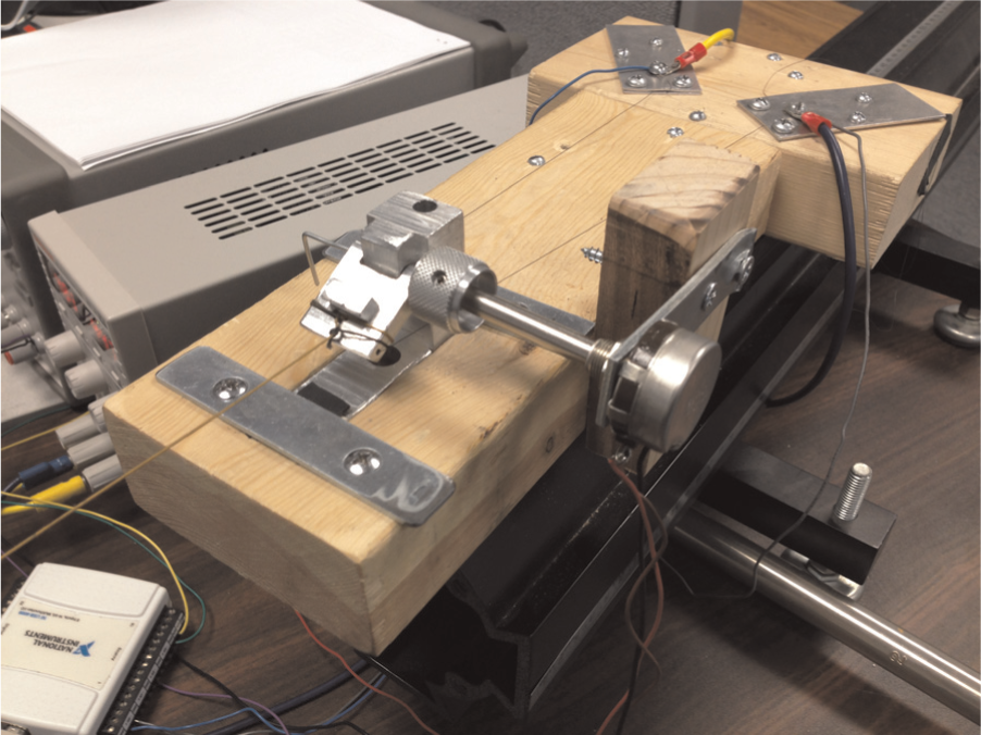
Locking mechanism experimental setup. Aluminum prototype of the locking mechanism with a 40.54-cm SMA wire as an actuator. The two ends of the SMA wire are fixed by two aluminum plates. A low-friction potentiometer is connected to the hinge of the locking mechanism for experimental verification.
The stress on the SMA wire is constant in this setup based on the following assumptions: (a) the length of the string and the SMA wire are very long compared to the movement of the peg. Therefore, the two angles (β and γ in Figure 6) are constant during the contraction within a small margin of error, (b) the two angles are also equal (β = γ) because the SMA wire and the string are leveled with each other, and (c) the weight of the peg is negligible. Figure 6 depicts the configuration of the experimental setup in which the force applied to the SMA wire is provided by the weight. The relationship of string tension and the total pulling force of the SMA wire is calculated using equation (12)

where Tstring is the tension of the string, mg is the weight of the peg, F is the total pulling force of the SMA wire, β is the angle of the SMA wire with vertical axis (dashed line), and γ is the angle of the string with vertical axis (dashed line).
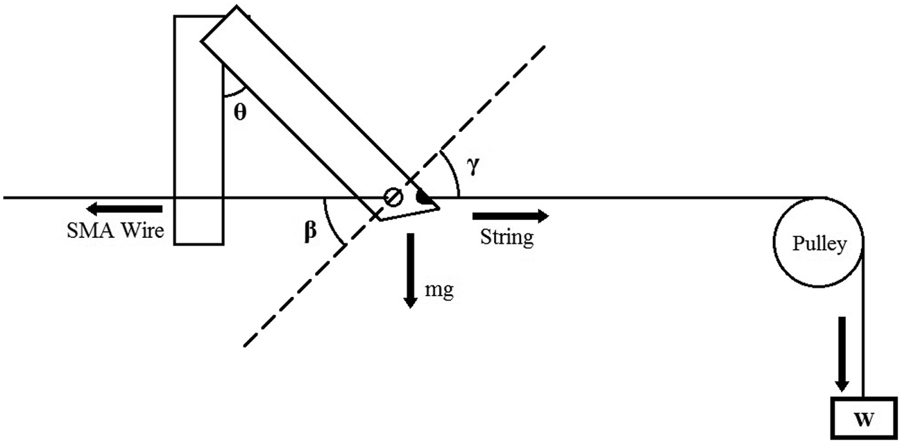
Schematic diagram of forces in the experimental setup.
Since the SMA wire is threaded through the peg, force applied to the SMA wire on each side is the half of F. Equation (13) shows the constant stress on the SMA wire, in which F is equal to the amount of the weight connected to the string (W)

where σ is the stress and r is the radius of the SMA wire. F is the total pulling force of the SMA wire.
The range of the locking mechanism angle (θ) is from the initial point of 60° (completely open) and the final point of 28° (completely closed). For the purpose of this experiment, the range is mapped to θ = 0 at 60° and θ = 32° at 28°. Evidently, the range for changes of the angle can be adjusted by the length of the SMA wire used in the locking mechanism, as well as the size and shape of the peg. For example, if the SMA wire is longer, the angle range between the initial and the final position is greater. The initial position may be adjusted by the initial distance between the hole in the peg and the two ends of the SMA wire.
In order to control the angle of the locking mechanism, a PI controller is used, as shown in Figure 1. The controller gains (Kp and Ki) must be chosen carefully due to the hysteresis characteristics and highly nonlinear behavior of the SMA wire. This is more important when the controller performs in the range of the phase transformation. In this range, if the desired position (or martensite phase fraction) is passed, returning to the desired position (or martensite phase fraction) is very slow. This is due to the slow cooling process and hysteresis characteristics. The controller gains selection has also a direct effect on the response time of the output. Therefore, optimized gains must be chosen to satisfy both the response time and the output accuracy. For the final positions close to 32° (martensite phase fraction close to 0), larger gains have to be chosen to achieve a precise and faster response. Figure 7 shows a sample output angle measured by the potentiometer for the desired angle of 30° (very close to the maximum possible angle).
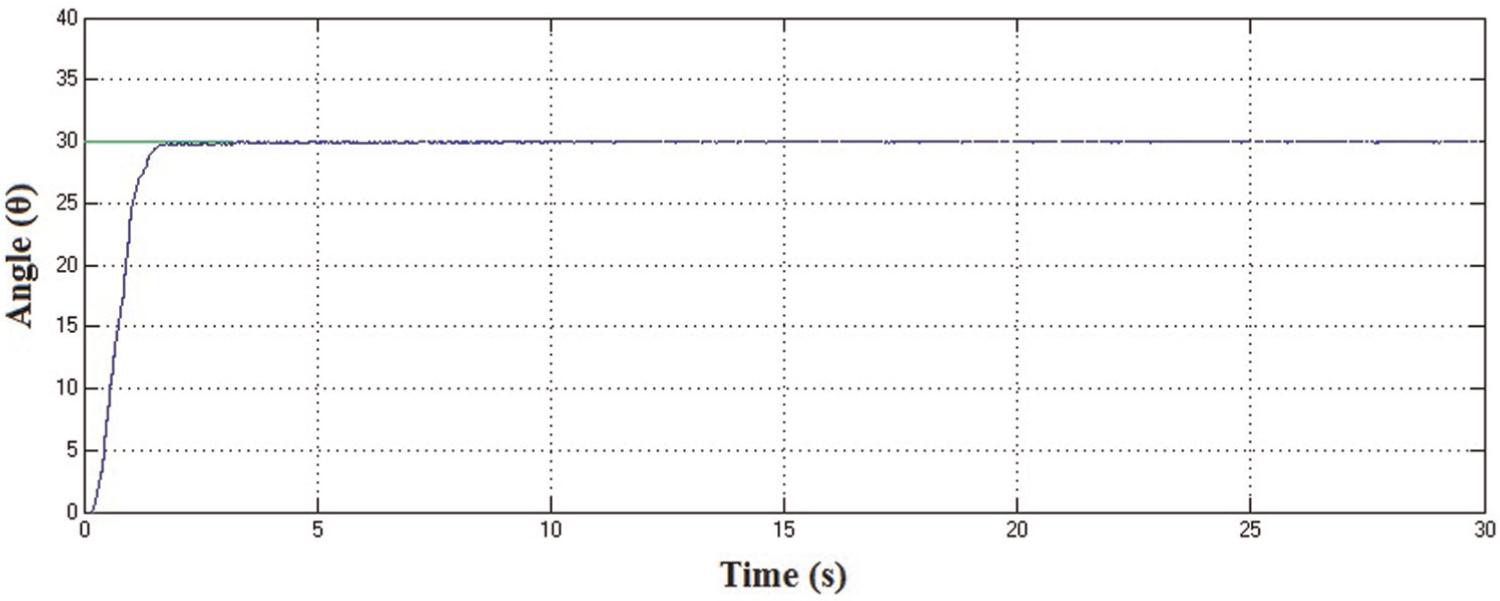
Angle of the peg of the locking mechanism for the desired angle of 30°.
The goal of the locking mechanism is to hold the suture for the LigLAP procedure. The possible diameter range of the sutures is between 0.4 and 1.2 mm. Therefore, the operation range of the system is about 4° based on the range of sutures (see Figure 8 and equation (14)). Equation (14) presents the range for the desired angles of the locking mechanism (Δθ), based on various suture diameters (D)

where Δθ is the range of changes in θ for various diameters of the sutures, h is the length of the leg, L is the length of the peg, and Dmax and Dmin are the minimum and maximum diameters, respectively.
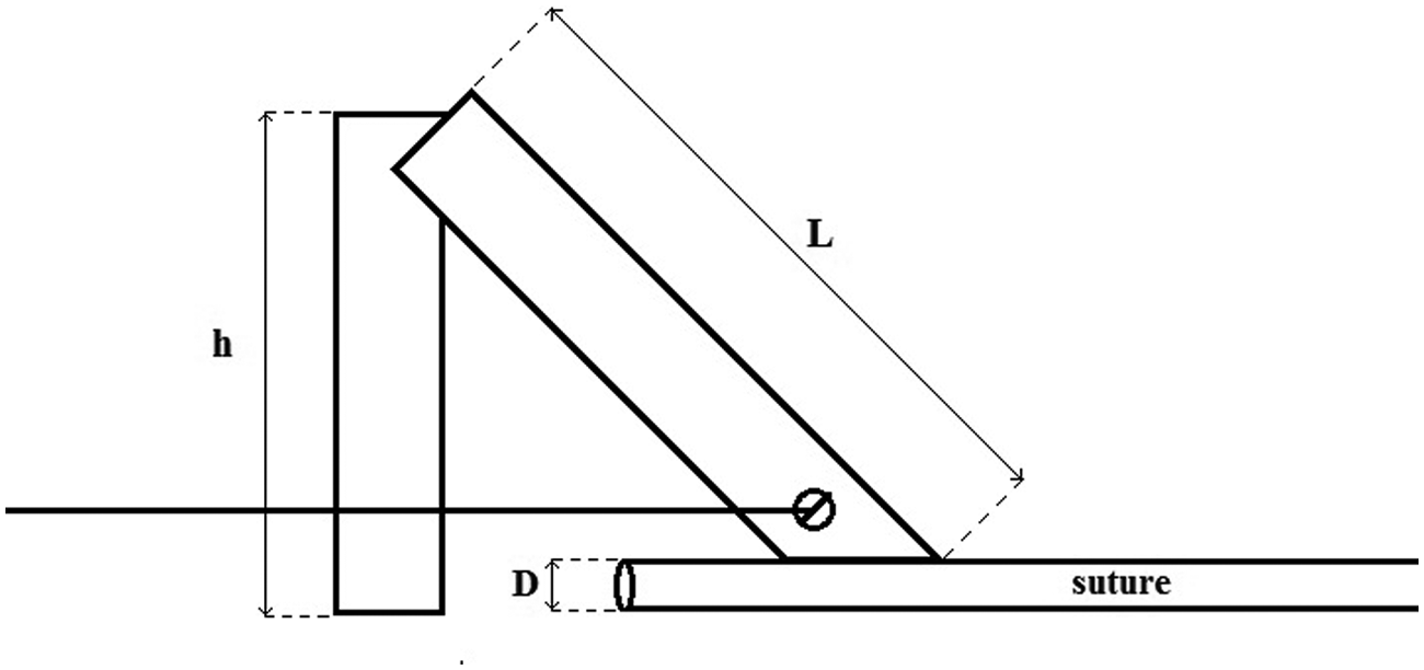
Diagram of the suture under the locking mechanism peg.
To find optimized controller gains, a wide variety of values for Kp and Ki have been tested. As predicted, especially for the desired angles that are not close to 32°, having Kp and Ki larger than appropriate values causes a positive error (the output is larger than the reference). In the next section, the steady-state errors for each desired angle are presented.
Results and discussion
The martensite phase fraction versus the measured angle of the locking mechanism (ξM−θ) curve is shown in Figure 9. The angle (θ) is measured using the potentiometer, and martensite phase fraction (ξM) is calculated based on the heating and resistance model and actual electrical resistance.
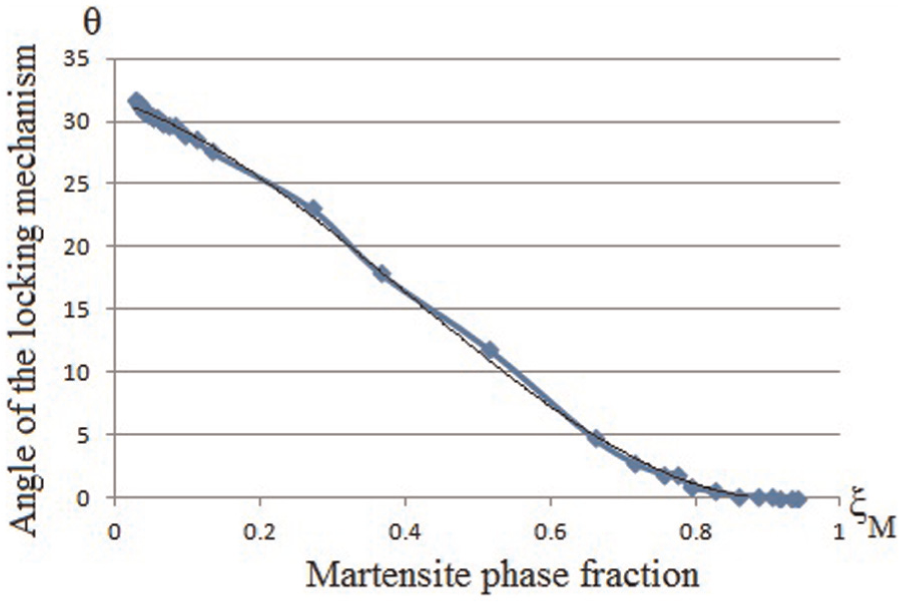
Angle of the locking mechanism versus martensite phase fraction.
The experimental results in Figure 9 show that the relationship between the martensite phase fraction and the angle of the locking mechanism is approximately linear, indicating the effectiveness of using ξ as a control variable. The best obtained controller gains for the desired angles between 22° and 26° (Δθ = 4) are in the range of 0.3 < Kp < 0.4 and 0.08 < Ki < 0.18. Figure 10 shows the martensite phase fractions and the angles of the locking mechanism for the desired angles of 22°, 23°, 25°, and 26° during 10 s of the system operation, with the controller gains set to Kp = 0.35 and Ki = 0.14. These controller gains are obtained for the desired angle of 23° and used for the entire operation range based on the different suture diameters. Moreover, the steady-state errors for the several angles of the locking mechanism are shown in Table 4.
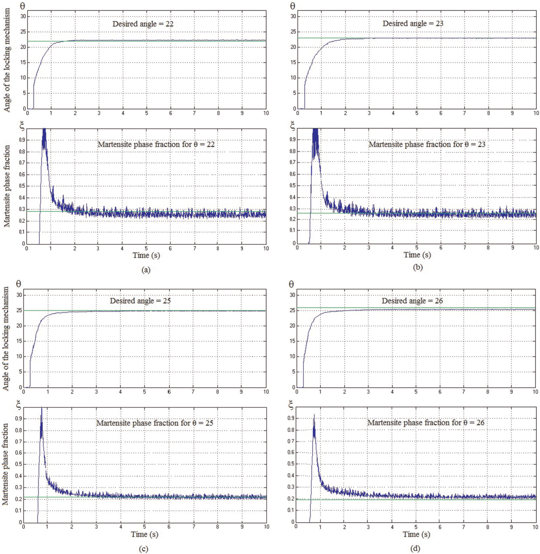
Results for the angle of the locking mechanism and martensite phase fraction for various desired positions based on various sizes of sutures: (a) Desired angle=22, (b) Desired angle=23, (c) Desired angle=25, and (d) Desired angle=26.
Steady-state errors for several angles of the locking mechanism based on various suture diameters.

In comparison with the non-resistive-based control methods in the literature (Kha and Ahn, 2006; Madden et al., 2004; Moallem and Tabrizi, 2009; Song, 2002; Troisfontaine et al., 1998), our resistive-based method can precisely control the position of SMA wires with the incorporation of the resistance model. The results confirm the validity of the resistance model, similar to the conclusions rendered by Song et al. (2011) and Novák et al. (2008).
Conclusion and future work
Due to the small space available in laparoscopic surgical devices, using external sensors is impossible or not preferred. The electrical resistance of SMA wires is an alternative feedback, in order to avoid using external sensors. In this article, an SRBC method for SMA wires to be used in the SMA-based locking mechanism for laparoscopic surgical devices is presented. Wire electrical resistance is measured to calculate the martensite phase fraction (ξM), which has a linear relationship with the strain of the SMA wire. This method has the advantage of using only a thin SMA wire without using any external sensors. In addition, wire electrical resistance can easily and accurately be measured in the application of SMA wire actuators. A hardware-in-the-loop control setup is used to control the angle of the locking mechanism using the method. The locking mechanism reaches the desired angle in all experimental trials. Very small steady-state errors in the experimental results (0.5° at most) show the accuracy of this method. As a result, the SRBC method accurately controls the SMA-based locking mechanism using only electrical resistance. It is concluded that the SRBC method is an alternative to the position/temperature feedback control algorithms. Moreover, the SRBC method does not require a non-model-based mapping for the relationship between electrical resistance and strain of the SMA wire, on the contrary to the methods that have employed mappings, such as neural network. In addition, SMA wires under various stresses can be controlled using this method, as the effect of stress is included in the resistance model of SMA wires. Furthermore, the mathematical model used in this article would suggest using model-based control strategies instead of trial and error control methods. Future work will design and develop SMA resistive-based control strategies to employ model-based control methods. In addition, the SRBC method can be used for other applications in which cost and space are limited and use of external sensors is impossible or costly.
Footnotes
Declaration of conflicting interests
The authors declared no potential conflicts of interest with respect to the research, authorship, and/or publication of this article.
Funding
This research received no specific grant from any funding agency in the public, commercial, or not-for-profit sectors.