
Abstract
Steel moment-resisting frames are prone to extensive damage in seismically active zones. Large permanent deformations in structural members following strong earthquakes can be mitigated using smart materials such as shape memory alloys. In this article, three-dimensional finite element analyses are conducted to study the seismic performance of beam–column connections incorporating shape memory alloy plates. Eight beam–column connection subassemblies with shape memory alloy plates in the plastic hinge of beam were analyzed under cyclic loading. Based on the numerical results, the recentering properties of superelastic shape memory alloy plates were found to be effective in reducing the residual drifts of a flange plate beam–column connection, while displaying an excellent ductility. In addition, shape memory alloy plates could prevent the occurrence of local buckling and damage in structural members. The new self-centering connections could also exhibit a good energy dissipation capability.
Keywords
Introduction
Steel moment-resisting frames (MRFs) experienced significant damage in the past earthquakes, such as the 1994 Northridge and 1995 Kobe earthquakes (Miller, 1998; Nakashima et al., 1998). The seismic performance of an MRF is highly dependent on the behavior of its beam-to-column connections. The brittle fractures of the welded MRFs have been attributed to several possible issues related to welding, materials, connection design, and detailing (FEMA-355D; Federal Emergency Management Agency (FEMA), 2000b). It was pointed out by Roeder (2002) that three vital characteristics of seismic-resistant connections, including connection strength, stiffness, and ductility, had not been considered in design of the pre-Northridge moment connections. In view of the potential defects and uncertainties associated with welding at the beam–column interface, significant design changes were implemented to the pre-Northridge moment connections (Engelhardt and Sabol, 1997). Beam–column connections with a reduced beam section (RBS) (Tremblay and Filiatrault, 1997), connections reinforced with cover plates (Engelhardt and Sabol, 1998), haunches (Uang et al., 2000), and side plates (Shiravand and Deylami, 2010) are examples of such modified connections. In these post-Northridge beam–column connections, the location of plastic hinges (where there are high levels of stress demands) is shifted away from the column face (FEMA-350; FEMA, 2000a).
The appearance of damage and residual deformations in steel moment frames under severe earthquakes is still inevitable. Yielding in the steel material leads to permanent deformations in steel MRFs. Consequently, repair costs increase and even demolishing of the building might be unavoidable. McCormick et al. (2008) reported that it is not economically feasible to repair steel buildings with residual drifts greater than 0.005 rad. An approach to providing self-centering in a building can be the use of smart materials such as shape memory alloys (SMAs). These metallic alloys are capable of reverting to their original shapes upon mechanical unloading or applying temperature. Several SMA-based devices and applications for civil and structural engineering have been investigated in the previous literature (Alam et al., 2007; Janke et al., 2005; Song et al., 2006; Wilson and Wesolowsky, 2005). The next section presents more details about SMAs. The idea of implementing SMA materials in steel beam–column connections has been proposed in a number of previous studies. Leon et al. (2001) performed experimental tests to study the efficiency of using martensitic NiTi tendons in a full-scale t-stub connection. The shape memory behavior of nitinol was exploited to recover 4% drifts in the connection. Ocel et al. (2004) studied the application of NiTi SMA bars in steel beam–column joints. Four martensitic SMA bars were used to connect the beam flange to the column flange. The tested connection was capable of dissipating energy while showing large ductility capacity with no strength degradation under cyclic loads up to 4% drift. Using SMA tendons in the connection, 54% and 76% of the beam tip displacement were recovered for connections with or without simulated dead loads, respectively. Abolmaali et al. (2006) experimentally studied the energy dissipative characteristics of t-stub connections with superelastic (SE) SMA fasteners. Even though the SMA fasteners showed early failure due to stress concentrations at the thread, a higher energy dissipation capability was concluded for the t-stubs with SMA fasteners compared to those with steel fasteners. Ma et al. (2007) used SE nitinol SMA as bolt shanks in an end-plate connection. By considering a lower moment capacity for the bolt cluster, the plastic hinge formed at the column face. Consequently, no local buckling occurred in the beam. The SE capability of SMA bolt shanks was utilized to recover deformations under cyclic loading. They suggested using a bolt shank of length up to 2.2 times of typical lengths to ensure a better ductility in the connection. DesRoches et al. (2010) studied the effect of both SE and martensitic SMA bars in steel connections. SE SMA connections were most effective in reducing residual deformations, while the martensitic SMA connections were most effective in controlling peak deformations. The seismic performance of frames with and without SMA connections was evaluated in a probabilistic framework (Ellingwood et al., 2010). Speicher et al. (2011) performed experimental tests on the cyclic behavior of an interior beam–column steel connection with SE NiTi tendons. The behavior was compared with those of connections utilizing tendons made of steel, NiTi, and SE NiTi parallel with aluminum. The connection incorporating SE NiTi tendons was able to recover 85% of its deformation after being loaded up to 5% drift. Hu et al. (2011) studied the application of SE NiTi bars in connections with concrete-filled tube (CFT) columns. The performance of the proposed t-stub connection was compared with conventional welded connections through performing nonlinear analyses of MRFs. A flexible behavior with limited recentering capability was observed for frames with the new connection. Nonlinear analysis and evaluations of composite moment frames (i.e. with concrete-filled steel tube columns) incorporating SMA connectors show the superior performance of these new smart connections (Hu and Leon, 2011).
This feasibility study intends to numerically investigate the effect of using ferrous-based SMA plates in steel beam–column joints. From previous research in the literature, a welded flange plate connection is selected. After calibrating the three-dimensional (3D) nonlinear finite element (FE) model, the new application of SMA plates in the plastic hinge region of the selected steel connection is introduced. Cyclic analyses are performed and the behavior of the SMA connections is compared with the steel one.
SMAs
SMAs are mainly known for their capabilities to recover their original shape after experiencing large deformations. This shape recovery is attributed to the phase transformation of SMA material. It happens upon either mechanical unloading or applying temperature. The shape recovery property of austenite SMA occurring after unloading is called superelasticity or pseudoelasticity (PE). When SMA is in its martensite phase, heating is required to restore deformations and this characteristic is known as shape memory effect (SME). The phase transformation behavior and thus recentering capability of SMA is dependent on different factors such as alloying, manufacturing, and fabrication process (Lagoudas, 2008).
SMAs in different forms of wires, rods, and plates have the potential to be used for various applications. Both Superelasticity and SME characteristics can be expected under varied loading conditions, including torsion, bending, tension, and compression (DesRoches and Smith, 2004). In an attempt to develop an SMA-based damping device for bridges, Adachi and Unjoh (1999) used NiTi SMA plates. The results of cyclic and shake table tests demonstrated that a martensitic SMA could provide a higher damping capability. Based on the numerical and experimental studies by Suzuki et al. (2004), the energy absorption of NiTi SMA plates under compressive loadings can be three times greater than that of aluminum plates. The results of experiments (Nemat-Nasser et al., 2005) to study the buckling behavior of NiTi SMA shells showed full recovery of the material. SE behavior as well as SME was observed under quasi-static compression tests. More recently, Mirzaeifar et al. (2013) presented the results of a three-point bending test on an SMA beam while providing a theoretical solution for bending analysis of SMA beams. In the past literature, there are several studies exploring the behavior of SMA plates from a material science perspective (Grolleau et al., 2009; Murasawa et al., 2006, among others).
Nitinol or NiTi is known as the most common SMA widely used in various scientific and engineering fields (Lagoudas, 2008). Strong PE and SME characteristics and also good corrosion resistance are among the factors which make these alloys suitable for different applications. However, manufacturing and training process of NiTi are expensive. A lot of effort has been made to develop other types of SMAs suitable for large-scale civil engineering applications (Ozbulut et al., 2011). Although Cu-based alloys are less expensive, they show poor ductility. As another alternative, low-cost Fe-based SMAs have been found to be a good candidate for this purpose. Fe-Mn-Si-based alloys exhibit good mechanical properties with a wide transformation hysteresis, good machinability, and weldability, and also good workability compared with properties of NiTi (Alam et al., 2007). Dong et al. (2009) introduced a new Fe-Mn-Si SMA with good shape recovery stress and shape recovery strain, which does not require any training/treatment process. Omori et al. (2011) proposed Fe-Mn-Al-Ni SMAs with good superelasticity and ductility. In contrast to NiTi, these Fe-based alloys can exhibit SE behavior with no significant sensitivity to temperature. More recently, Li et al. (2013) developed a new Fe-based SMA with simple manufacturing process, and good mechanical behavior, showing SME suitable for smart structural applications. These findings imply the improvements toward mass-scale production of SMA with proper characteristics in the future. Since Fe-SMA shows more potential in terms of manufacturing, welding, and cost, here, utilizing ferrous-based SMA plates welded to steel section was assumed.
FE model
In order to study the cyclic behavior of steel beam–column joints, 3D models were generated, meshed, and analyzed using the FE software, ANSYS (Release 14; ANSYS, Inc., 2012). Figure 1 shows the beam–column joint specimen, which is one of the welded flange plate connections designed and tested by Gholami et al. (2013). This beam–column specimen is taken to represent an exterior joint in a moment-resisting steel frame. It contains a mid-span beam and a column, which spans the mid-height to mid-height of story. An I-shaped
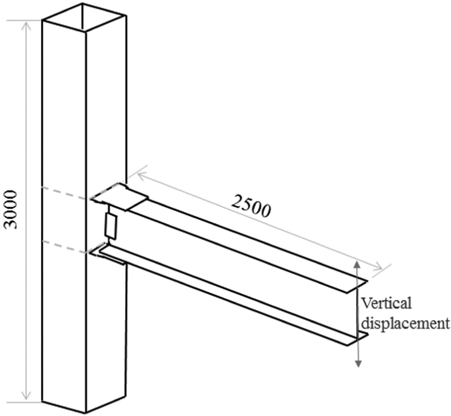
Schematic representation of the studied beam–column subassembly (mm).
A bilinear stress–strain relationship was adopted for modeling steel material (Figure 2). The modulus of elasticity and Poisson’s ratio were taken as 200 GPa and 0.3, respectively. The mechanical properties used for steel are provided in Table 1 (Gholami et al., 2013). The material nonlinearity and plasticity were included in the modeling by assuming kinematic hardening and von Mises yield criteria. The SMA model in ANSYS was used to capture the SE behavior of these materials. A further description of the SMA model is provided in section “Incorporation of SMA plates.”
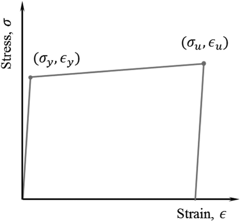
Stress–strain relationship of steel material.
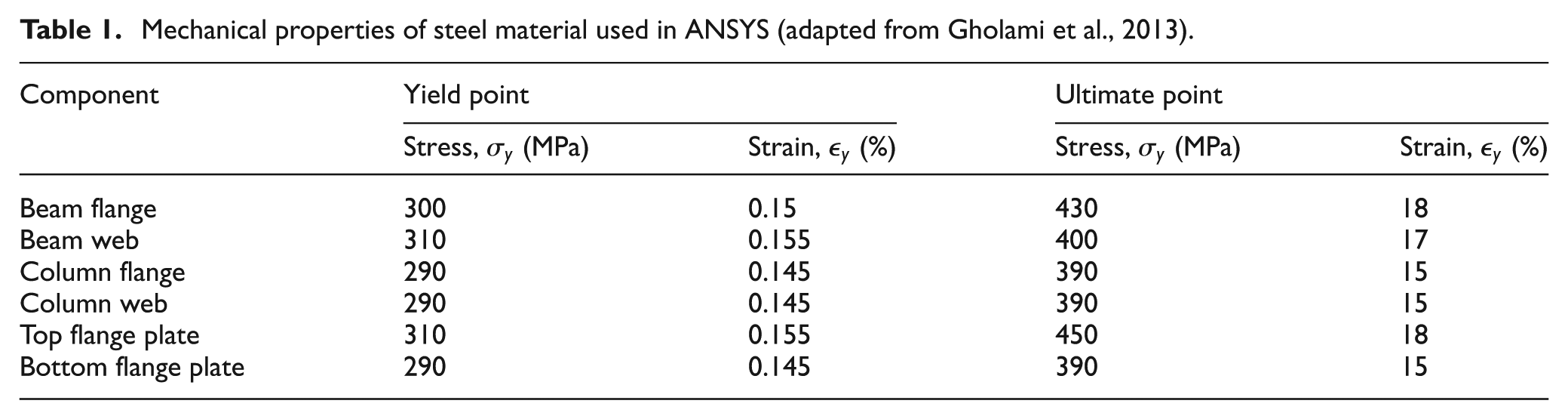
Mechanical properties of steel material used in ANSYS (adapted from Gholami et al., 2013).
To better capture the detailed structural behavior, including local buckling of the beam, and lateral deformations, a complete 3D beam–column connection was modeled in ANSYS (Figure 3). The entire beam–column model was meshed using 3D eight-node solid elements (SOLID185). This element has 3 degrees of freedom at each node and provides capabilities such as plasticity, stress stiffening, large deflection, and strain capabilities (ANSYS, Inc., 2012). Figure 3 shows the steel beam–column subassembly with a mapped mesh. A finer mesh was created in the near-joint regions. In order to ensure that a desirable mesh density is obtained, proper sizes were assigned to a number of lines before volume meshing. Element sizes were also used to control the generated mesh. It should be noted that welding was not explicitly modeled in this study.
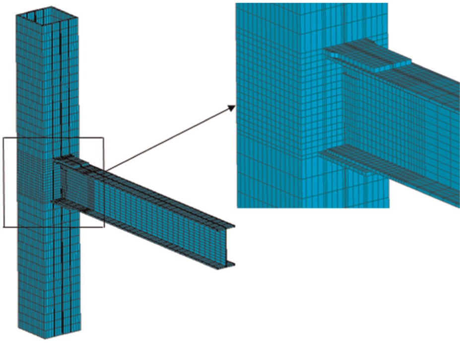
Finite element model of the connection.
Boundary conditions are the same as detailed in the experiment (Gholami et al., 2013). By defining constraints on nodes, the beam was laterally restrained at two lengths of 0.7 and 2.3 m. In addition, pin support conditions at the bottom and top nodes of the column were considered in the model.
A displacement control approach was used in this study and displacement loads were applied to the beam tip nodes. Geometric nonlinearity was included by choosing large displacement analysis. A nonlinear static analysis was performed and the automatic time stepping option was chosen. To avoid convergence problems, an upper limit on the time step size was defined (ANSYS, Inc., 2012). It should be noted that the default convergence criteria and the optimized nonlinear solution were used in the analysis. Table 2 provides the cyclic loading details in accordance with FEMA-350. Peak deformation is the story drift angle defined as the maximum vertical displacement of the beam divided by the beam mid-span length (Figure 4).
FEMA/SAC cyclic loading protocol (FEMA-350).
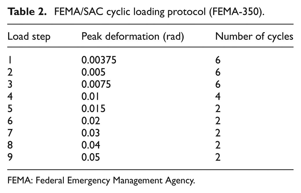
FEMA: Federal Emergency Management Agency.
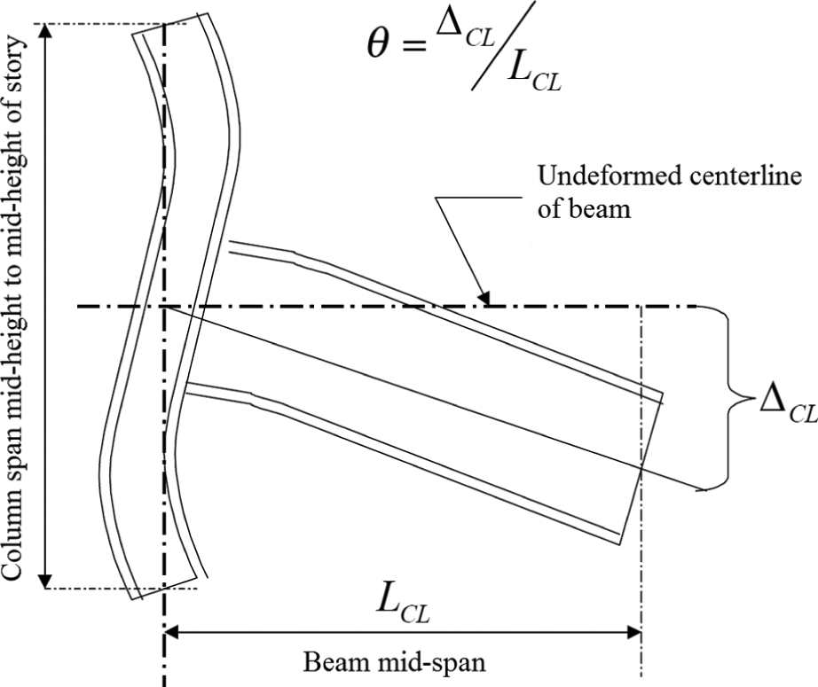
Definition of story drift angle (FEMA-350).
Verification of the FE analysis
The moment at the column face is depicted versus the story drift angle in Figure 5. The cyclic response obtained from the numerical analysis is compared with the experimental study reported by Gholami et al. (2013). As can be seen, the FE model is capable of simulating the cyclic behavior of the beam–column connection in terms of stiffness, strength, ductility, and strength degradation. Based on the cyclic response of the beam–column connection, a large amount of energy is dissipated through the material yielding. The connection is capable of accommodating a story drift angle of at least 0.04 rad. In addition, the flexural capacity of the connection measured at the column face is higher than 80% of the plastic moment capacity of the beam. This demonstrates that the beam–column specimen achieves the strength and ductility requirements of American Institute of Steel Construction (AISC) Seismic Provisions for special moment frames (AISC, 2010).
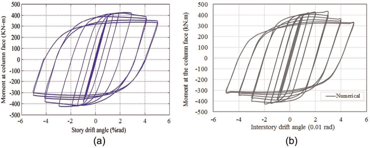
Hysteresis curves obtained from (a) experiment and (b) finite element analysis.
The strength degradation in the hysteresis curves is attributed to the occurrence of local buckling and plastic hinges in the beam flanges at drifts beyond 0.03 rad. The hinge location distance can be estimated as per FEMA-350. It occurs at a distance on the order of 0.300 m (equal to the length of flange plates) from the column face. Indeed, using flange plates in the connection, the plastic hinge location has been shifted away from the face of the column. As a result of this local buckling of the beam section, a large residual deformation remains in the specimen. This can also be observed from Figure 6. The equivalent plastic strain distribution in the joint is compared to the test specimen.
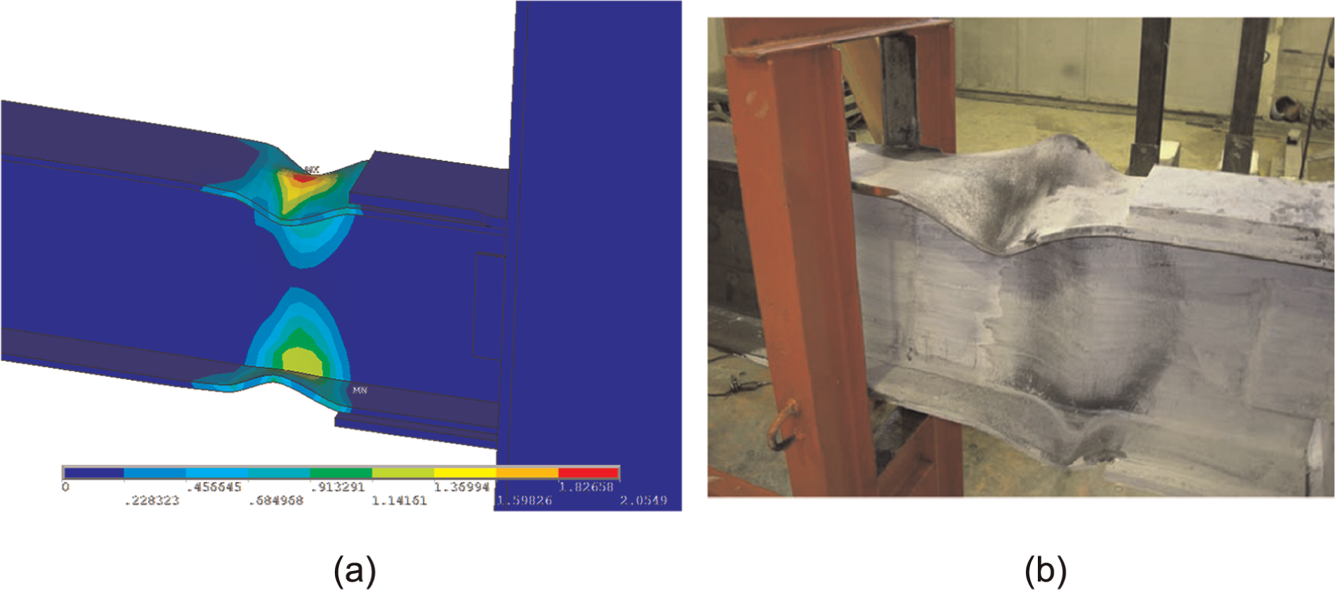
(a) Equivalent plastic strain from FE analysis in comparison with (b) the tested specimen.
Incorporation of SMA plates
In order to reduce the residual deformations of the steel beam–column joint, the cyclic response of connections incorporating SMA plates is numerically studied. Ferrous SMA plates are assumed to be used in the plastic hinge region of the beam to restore deformations and, hence, mitigate damage in the beam–column connection. Throughout this study, it was assumed that the SMA plates are fully welded to steel material.
In ANSYS, the SE behavior of SMA was simulated using Auricchio’s model. In this model (Auricchio, 2001), the material undergoes large deformation without showing permanent deformation under isothermal conditions (ANSYS, Inc., 2012). The SMA model considered in this study is temperature and rate independent. This model does not account for the accumulated residual deformations of the material under cyclic loading. However, it should be noted that previous researches (Alam et al., 2008; Andrawes et al., 2004) have shown that including the cyclic loading effects in the SMA model has little effects on the results of studies aimed at evaluating the effectiveness of SMA for seismic applications. Another study performed by Zhu and Zhang (2013) indicates that rate-independent models can be used for SE SMA in the seismic analyses of structures, provided that parameters used in the model are calibrated with experimental data. Figure 7 shows the idealized stress–strain diagram of SE behavior.
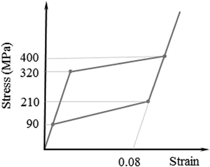
Assumed idealized stress–strain relationship for ferrous SMA.
The assumed mechanical properties for ferrous Fe-Mn-Al-Ni SMA were selected considering the experimental data reported by Omori et al. (2011). The elastic modulus of SMA in the austenite phase was assumed to be 98 GPa. Furthermore, a maximum residual strain of 0.08 (representing the plateau length within which the deformation in the material can be fully recovered) was considered in the FE analysis.
In order to examine the new applications of SMA plates, eight different cases were studied through the FE analysis. Figure 8 illustrates the beam–column models incorporating SMA plates. In Case 1 (SMA-FF), SMA was used as part of the beam flange. In Case 2 (SMA-FW), SMA was used as part of the flange and web of the beam. In Cases 3 and 4 (SMA-FF-Ex and SMA-FW-Ex), local reinforcements were applied in the form of providing extra flange plates adjacent to the plastic hinge region. The goal was to force the formation of plastic hinges in the SMA material rather than steel. This allowed to fully utilize the beneficial recentering properties of SMA. The length and thickness of the extra flange plates were taken as 200 and 20 mm, respectively. For the SMA plates, two different lengths of 100 and 150 mm with the same thickness as the beam flange (i.e. 12 mm) were considered. As can be seen in Figure 8, the steel beam flange or web is replaced by the SMA plate. Overall, eight models incorporating SMA plates were analyzed. These beam–column models are also listed in Table 3. The differences between the considered models include the length of SMA plates, the use of extra steel flange plates, and the use of SMA plates either in the beam flanges only or in both flanges and web. The next section presents the results of the FE analyses of these new connections, while comparing the response with the verification case. The steel connection studied for the validation of the numerical analysis was used as a benchmark beam–column model.
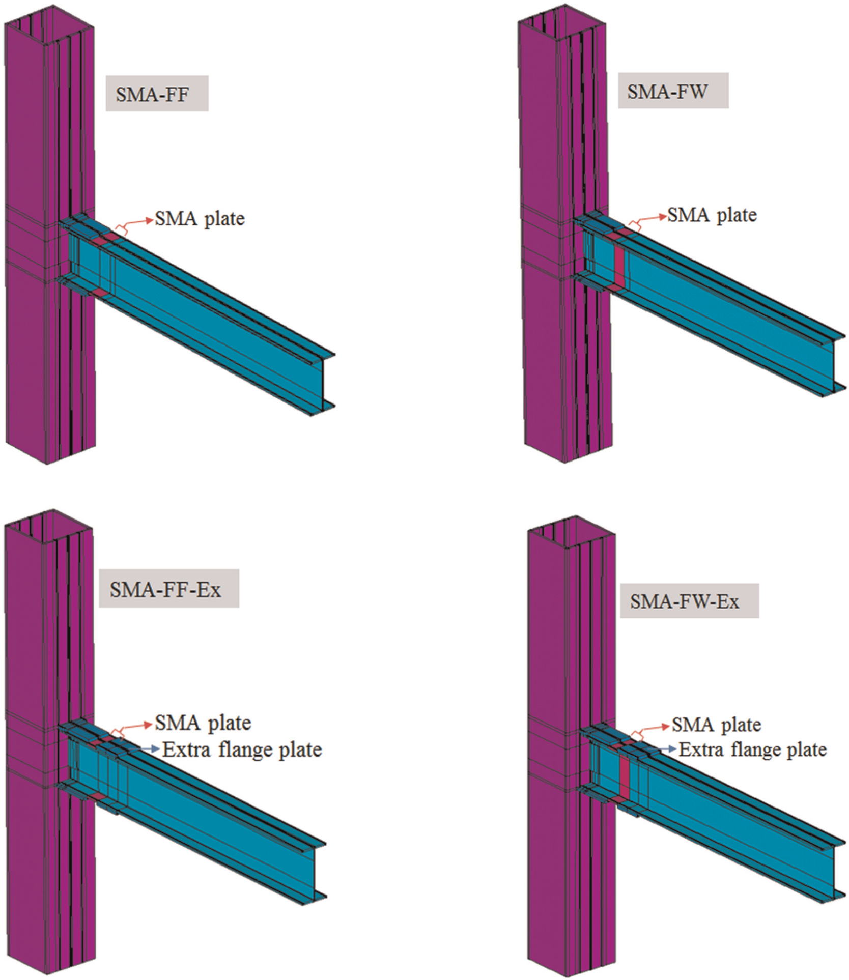
Different beam–column models incorporating SMA plates.
SMA connections analyzed in this study.
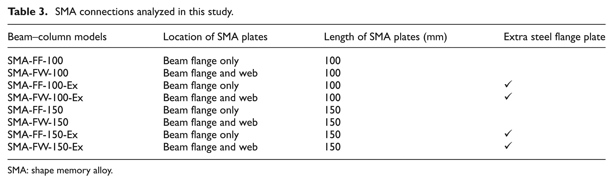
SMA: shape memory alloy.
Results and discussions
The cyclic performances of the new SMA connections were compared with the performance of the steel beam–column connection subassembly (benchmark model). Figure 9 plots moments at the column face versus interstory drift angles for the connections incorporating SMA plates of size
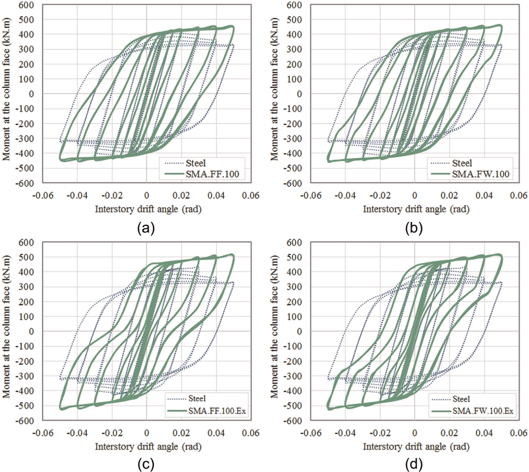
Moments versus interstory drift angles for connections with SMA plates of 100 mm long for (a) SMA-FF-100, (b) SMA-FW-100, (c) SMA-FF-100-Ex, and (d) SMA-FW-100-Ex.
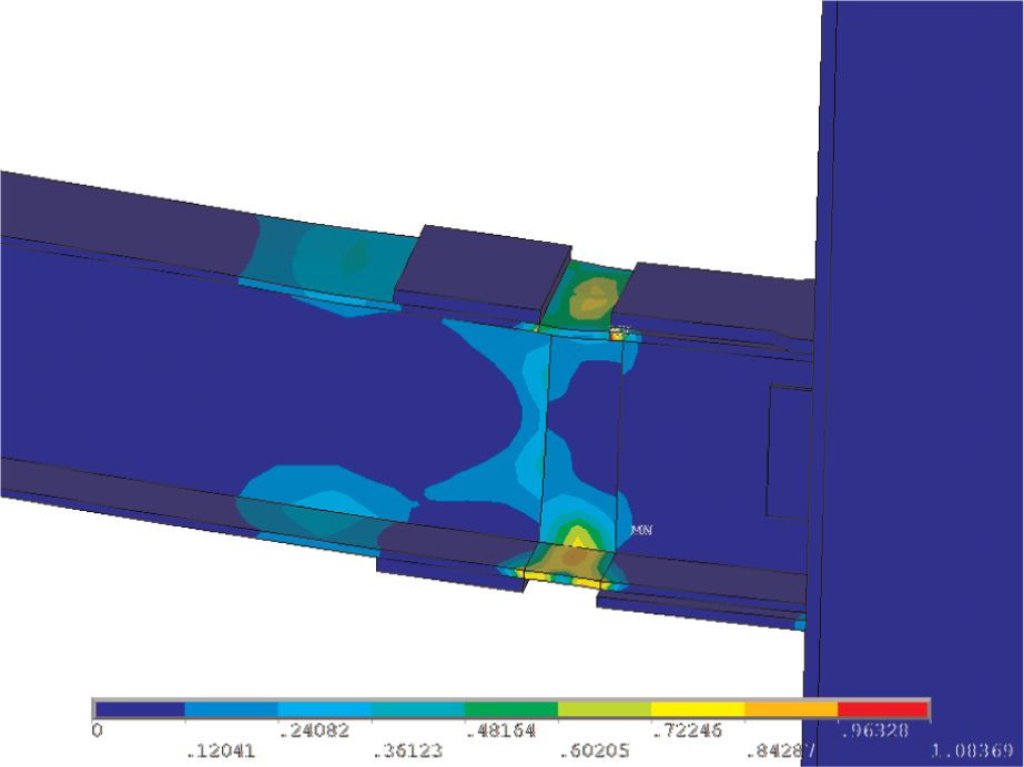
Equivalent plastic strain distribution in SMA-FW-100 at the end of cyclic loading.
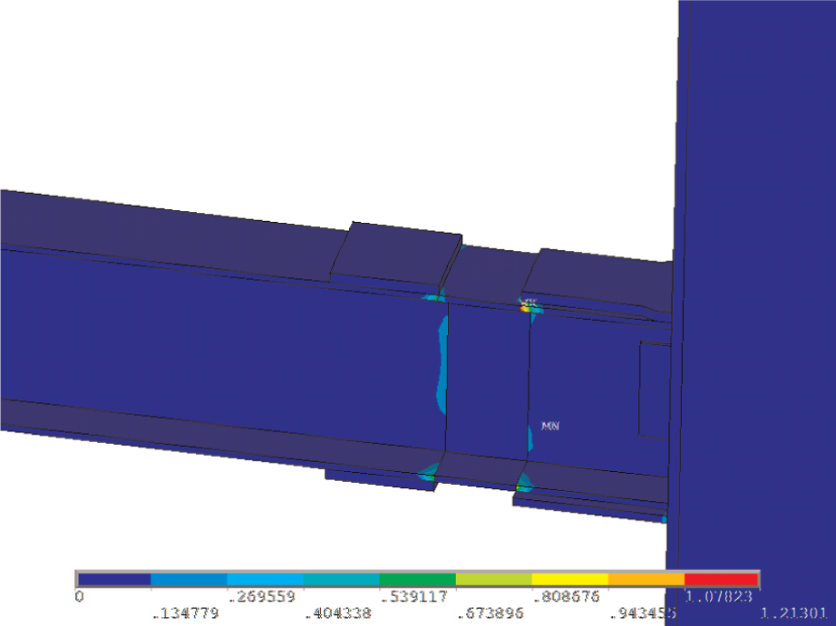
Equivalent plastic strain distribution in SMA-FW-100-Ex at the end of cyclic loading.
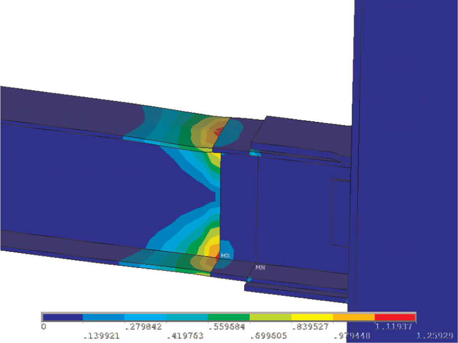
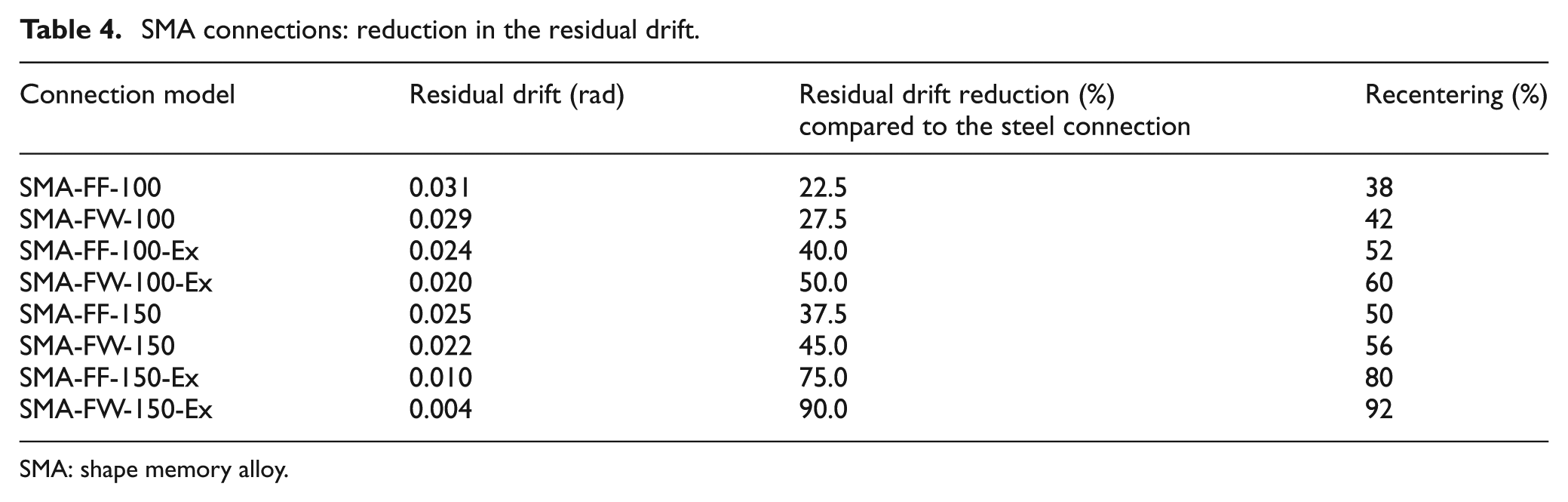
Figure 12 depicts the hysteresis curves for the connection models employing SMA plates of 150 mm long. Using longer SMA plates, more reduction in the residual drifts is achieved. The permanent drift values are 0.025, 0.022, 0.010, and 0.004 rad for SMA-FF-150, SMA-FW-150, SMA-FF-150-Ex, and SMA-FW-150-Ex models, respectively. This indicates the efficiency of SMA plates in decreasing the residual deformations of the beam–column connection. When plastic hinges occur only in the SMA plates, the maximum recentering can be obtained. Using extra flange plates and also adequate SMA material in SMA-FW-150-Ex, it was assured that plastic hinges occur in the SMA material, and consequently, recentering capability of SMA plates is fully utilized. This is confirmed by examining the distribution of equivalent plastic strain in the connection after unloading. As can be seen in Figure 13, the plastic deformations are controlled, governed, and limited by SMA plates in the beam web and flanges. Table 4 provides the amounts of recentering and residual drift reduction for different SMA connections. Residual drift reduction denotes the percentage of reduction in the residual drift of connection compared to the residual drift in the steel benchmark model (i.e. 0.040 rad). Furthermore, the recentering was calculated as the difference between the maximum drift (i.e. 0.05 rad) and residual drift divided by the maximum drift in the connection. For instance, 92% of the maximum drift (i.e. 0.05 rad) was restored when SMA plates of 150 mm long were used in part of the beam web and flanges in conjunction with extra steel flange plates.
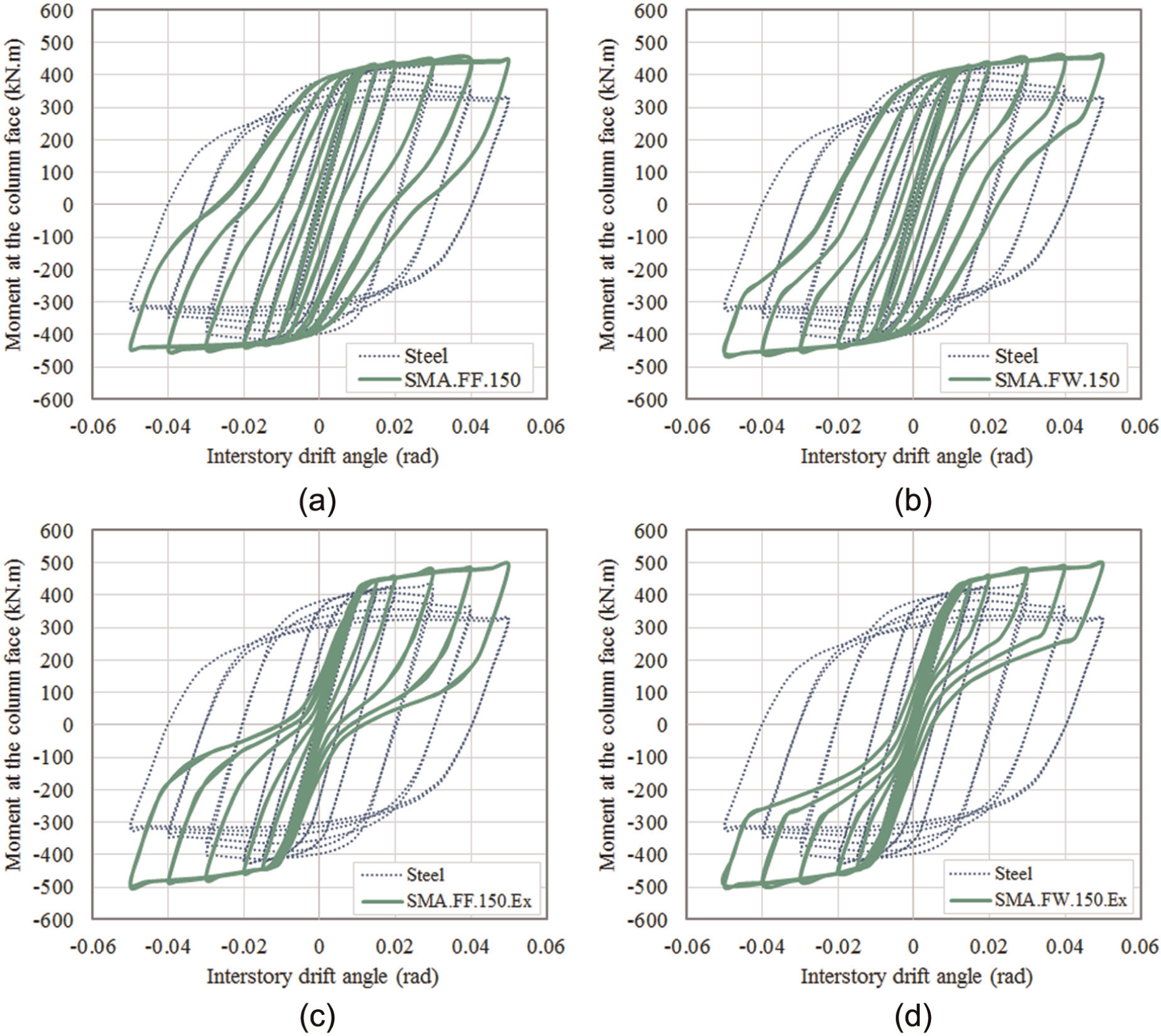
Moments versus interstory drift angles for connections with SMA plates of 150 mm long for (a) SMA-FF-150, (b) SMA-FW-150, (c) SMA-FF-150-Ex, and (d) SMA-FW-150-Ex.
Equivalent plastic strain distribution in SMA-FW-150-Ex at the end of cyclic loading.
SMA connections: reduction in the residual drift.
SMA: shape memory alloy.
The total dissipated energy of each connection with SMA plates is lower than that of the benchmark steel connection. Figure 14 illustrates the energy dissipation capability and also the recentering of each connection model. The dissipated energy was calculated from the area enclosed by force–deformation loops. Beam–column models SMA-FF-100 and SMA-FW-150-Ex display the maximum and minimum energy dissipation capability, respectively. These energy dissipation capabilities are 8% and 58% less compared to that of the benchmark model. The more recentering capability the SMA connection possesses, the less energy it dissipates. Because of the flag-shaped hysteresis of SMA, the lower dissipated energy was expected.
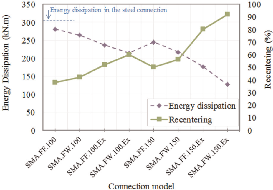
Total energy dissipation and recentering capabilities of different SMA connections.
In addition to the recentering capability, SMA plates are effective in preventing the occurrence of local buckling in the beam section. As a result, more stable hysteresis with no strength degradation can be achieved. This can compensate for the lower energy dissipation of SMAs due to their flag-shaped hysteresis nature. Moreover, the initial stiffness of the moment–drift curves for SMA connections is comparable to that of the steel one. This is another promising characteristic of the new application of SMA plates considering the fact that the modulus of elasticity of SMA is lower than that of steel. Overall, steel beam–column connections with SMA plates, if properly proportioned and implemented, can revert back to their original position, while achieving a stable hysteresis with good energy dissipation and without strength degradation.
Limitations of this application
There are certain issues currently hindering the new application of SMA plates in steel MRFs. These mainly include cost, manufacturing, and joining technology. The first issue is the cost of SMA plates possessing the desirable SE properties. In view of the recent improvements (e.g. Li et al., 2013) in the material science and the developments of low-cost Fe-based SMAs, there can be a significant reduction in the fabrication and final cost of SMA production. Furthermore, providing buildings with recentering properties can prevent damage in other structural systems. That is, SMA applications can reduce economic losses and minimize human risk associated with natural disasters such as earthquakes. Life cycle cost analysis of SMA-based framed buildings should be conducted to investigate the effect of such smart materials on the total constructional cost. The other factor is the lack of welding technology for joining of SMA plates to each other and also to the steel material. Lin et al. (2000) showed that Fe-based SMAs can be laser welded; however, it should be followed by annealing treatment. Zhou et al. (2011) reported on the joining of Fe-based SMA using cross-flow laser welding. They used optimal welding processing parameters and observed that the tensile strength of the welded Fe-based joint can achieve 93.5% of the base material strength. At this point, the ideal welding technology may not be readily available in the market. However, during the recent years, efforts have been made in the material science to study the joining methods for SMA materials (Akselsen, 2010). For instance, Zhao et al. (2010) improved the mechanical properties of laser-welded NiTi alloy. Higher tensile strength and toughness were observed for welded specimen using additives in the welding process. Santos et al. (2013) noted that promising results have been observed in the preliminary studies of using laser for brazing NiTi to stainless steel. This condition could be even better in the case of using Fe-based SMAs as Alam et al. (2007) pointed out that Fe-Mn-Si-based alloys exhibit good machinability and weldability compared with NiTi.
Conclusion
The effect of using SMA plates in steel beam-to-column connections was studied through a 3D FE analysis. The numerical modeling was validated by comparing the results against experiments reported in the literature. The same beam–column connection that was analyzed for the verification of the numerical modeling was used to explore the efficiency of SMA plates. In order to take advantage of the recentering properties of smart materials, SMA plates of either 100 or 150 mm long were incorporated in the plastic hinges of steel beam. Applications of SMA plates in beam flanges and also in beam web in addition to the flanges were considered as different connection models. Furthermore, in some cases, extra flange plates were used for beam to restrict the formation of plastic hinges in the SMA length of the beam and fully utilize the recentering capabilities of SMA. The cyclic performance of different beam–column models was discussed in comparison with the benchmark connection. The following conclusions can be drawn from the results of this numerical study:
The FE model was verified by comparing the cyclic behavior of steel beam-to-column connection model with previous experimental results. Good accuracy was observed.
The beam–column connections equipped with SMA plates exhibited lower residual interstory drift angles as compared to that of the benchmark (steel) connection. The new SMA connections were able to recover deformations so that 38%–92% recentering was obtained for different SMA connection types.
Lower residual drifts were observed when SMA plates were used in the beam web in addition to the beam flanges. Since the beam flanges have more contributions under flexural loadings, the application of SMA plates in the beam web as well as the flanges may not significantly affect the connection behavior. For example, the residual drift was 0.031 rad for the model incorporating SMA plates of 100 mm long only in the beam flanges. This amount reduced by 6.4% when SMA plates were used in the beam web in addition to the flanges.
When longer SMA plates were employed, lesser permanent drifts remained. In other words, the recentering capability of the SMA-based connection was increased (by at least 24%) when SMA plates of 150 mm long were employed instead of 100 mm.
Using extra steel flange plates, the beam section was reinforced so that the formation of plastic hinges was confined to the SMA material. As a result, yielding in the steel material was avoided and higher recentering capability (at least 27%) was achieved.
In addition to providing recentering capability in the connection, SMA plates were effective in preventing the occurrence of local buckling in the beam section. Therefore, the SMA connections exhibited more stable hysteresis with no strength degradation.
Due to the flag-shaped hysteresis of SMA material, the beam–column connections equipped with SMA plates displayed lower amounts of energy dissipation capability when compared with the steel benchmark connection. The total amounts of energy dissipated by the SMA connections were from 8% to 58% lower than that of the steel connection.
It should be noted that the SMA model considered in the analysis is rate and temperature independent and does not account for the accumulated residual deformations in the SMA material. The results obtained from this proof of concept study seem promising. However, there are some constraints for its large-scale application in building structures. Cost, manufacturing, and proper welding/joining of SMA plates are among the main factors that need further research and studies in the future. Development of new low-cost SMAs such as Fe-based alloys with the ease of machinery and material training can significantly reduce the cost. Even though there are currently some drawbacks for this application, the results of this numerical study suggested a potential application of SMA plates. This can accelerate the research for studying and inventing the needed joining technology. Moreover, the authors believe that the results of this study (even with its current limitations) can be of great interest to researchers, most notably, in the field of earthquake engineering. Further research is necessary to study all the aspects of this application and eliminate the drawbacks.
Footnotes
Declaration of conflicting interests
The authors declared no potential conflicts of interest with respect to the research, authorship, and/or publication of this article.
Funding
The financial contribution of Natural Sciences and Engineering Research Council of Canada (NSERC) through Discovery Grant was critical to conduct this research and is gratefully acknowledged.