
Abstract
Piezoelectric energy harvesters can be used to convert ambient energy into electrical energy and power small autonomous devices. In recent years, massive effort has been made to improve the energy harvesting ability in piezoelectric materials. In this study, reduced graphene oxide was added into poly(vinylidene fluoride) to fabricate the piezoelectric nanocomposite films. Open-circuit voltage and electrical power harvesting experiments showed remarkable enhancement in the piezoelectricity of the fabricated poly(vinylidene fluoride)/reduced graphene oxide nanocomposite, especially at an optimal reduced graphene oxide content of 0.05 wt%. Compared to pristine poly(vinylidene fluoride) films, the open-circuit voltage, the density of harvested power of alternating current, and direct current of the poly(vinylidene fluoride)/reduced graphene oxide nanocomposite films increased by 105%, 153%, and 233%, respectively, indicating a great potential for a broad range of applications.
Keywords
Introduction
With the development of electronics technology, the power consumption of portable devices decreases continuously, thus the self-power function becomes feasible. Moreover, in some special situations, replacement of batteries is inconvenient or costly (Ramirez, 2010). Therefore, energy harvesters, converting ambient energy (e.g. vibration) into electrical energy, have been developed. Compared to battery-powered devices, these devices are more environment-friendly and have longer operating lives, attracting increased attention from researchers (Arroyo et al., 2013; Erturk, 2009; Priya, 2005). Among various energy harvesting systems, piezoelectric material–based devices have many advantages.
To date, lead zirconate titanate (PZT) is the most commonly used piezoelectric material in the energy harvesters (Beeby et al., 2006; Chen et al., 2010; Lynch et al., 2004; Mitcheson et al., 2008; Ramadass and Chandrakasan, 2010). In spite of its good performance, PZT is fragile and susceptible to fatigue (Guo et al., 2003). In addition, the toxicity of lead oxide in PZT has raised significant health and environment concerns. Therefore, a great technical challenge in the development of energy harvesting technology is to replace PZT with eco-friendly materials. Possible candidates include piezoelectric polymers (e.g. poly(vinylidene fluoride) (PVDF) and its copolymer) as they are not toxic, recyclable, and resistant to halogen, acid, and fatigue (Liu et al., 2011). Moreover, they are highly flexible and can be applied on the curved structural surfaces (Kim et al., 2013; Liu et al., 2011). For instance, Elvin et al. (2001) fabricated a wireless strain sensor using PVDF films. Through a simple bending experiment, the characteristics of the self-power strain sensor related to frequency and applied load were investigated. Wireless communication was also realized. In addition, it can be used to power a rechargeable battery. Moreover, a bioinspired piezo-leaf architecture converting wind energy into electrical energy was studied (Li et al., 2011), in which the maximum output power and maximum power density approached 600 µW and 2.0 mW/cm3, respectively. Granstrom et al. (2007) developed a novel strap and the maximum harvested power reached 3.75 mW and the maximum power density approached 2.7 mW/cm3. Since the mechanical properties of PVDF polymer are very similar to those of nylon (i.e. the material of backpack strap), it is then possible to replace nylon with PVDF for enhanced energy harvesting capacity. Liu et al. (2009) investigated the active energy harvesting circuit using switch-mode power electronics to control the voltage and/or charge on a piezoelectric device for effective energy conversion and demonstrated it with a multilayer PVDF polymer device. The experiments showed that the active energy harvesting approach generated about five times of energy for the same mechanical displacement compared to the passive rectifier-based circuit.
On the other hand, to improve some physical properties of PVDF (e.g. piezoelectricity), various nanofillers such as carbon nanotube (CNT) and graphene were used to prepare PVDF-based nanocomposites (Alamusi et al., 2012; Kim et al., 2009; Lee et al., 2008; Levi et al., 2004; Wu et al., 2013). For instance, Levi et al. (2004) blended CNT with PVDF and its copolymers. The improvements of pyroelectricity, piezoelectricity, and mechanical properties were observed. It indicated that the enhancement resulted from morphological changes in the polymer crystallinity. The X-ray diffraction (XRD) and differential scanning calorimetry (DSC) analysis confirmed the polymorph formation. Tang et al. (2012) synthesized PVDF/reduced graphene oxide (rGO) nanocomposite films by in situ reduction process from PVDF/graphene oxide (GO) at 200 °C for 2 h. The electrical conductivity, dielectric permittivity, and loss tangent increased dramatically at the content over the percolation threshold, that is, 0.016 vol.%. In Kim et al. (2009), Lee et al. (2008), and Wu et al. (2013), multi-walled carbon nanotube (MWCNT) was blended with PVDF to enhance its piezoelectricity. As reported by Lee et al. (2008), the maximum increase in piezoelectric strain coefficient d31 was 10% at 0.2 wt% addition of MWCNT. Moreover, the authors of this article showed that PVDF/MWCNT film at 0.05 wt% MWCNT loading had the maximum increase in piezoelectricity (i.e. 24%), compared to neat PVDF (Wu et al., 2013). Rahman et al. (2013) fabricated PVDF/rGO nanocomposite films by in situ thermal reduction of PVDF/GO films. Compared to pure PVDF films, the increasing ratio of output voltage for PVDF/rGO films was 51% at the resonance frequency (i.e. 41 Hz). They reported a maximum power of 36 nW at a load resistance of 704 kΩ at the resonance frequency and an acceleration of 1 g (9.8 m/s2). In addition, a dramatic increase in dielectric constant at low frequency (<1000 Hz) was also observed. We also reported a remarkable twofold increase in PVDF’s piezoelectricity by addition of 0.05 wt% rGO (Alamusi et al., 2012), in which we investigated the open-circuit output voltage under different frequencies.
As described above, to date, most reports focus on prototyping PVDF films, utilizing more effective energy harvesting circuits, or modeling the piezoelectric devices. Although there are some limited reports on PVDF-based nanocomposites with various nanofillers, they mainly focus on the mechanism of morphological behavior or thermal, mechanical, ferroelectric, and piezoelectric properties. To the best of the authors’ knowledge, there has been no report on the energy harvesting capability of PVDF-based nanocomposite with rGO. In this study, rGO was added into PVDF to fabricate nanocomposite films. The experiment showed that the energy harvesting or conversion capability was dramatically improved by adding rGO as compared to pristine PVDF films. XRD and Fourier transform infrared spectroscopy (FTIR) were used to uncover the corresponding mechanism. The variation in internal crystal structure induced by rGO, especially the piezoelectric crystal content (i.e. β-phase content in PVDF), is considered to be the main reason. Moreover, a theoretical model for predicting the harvested power was used to explain the observed experimental phenomena. We believe that this powerful piezoelectric PVDF/rGO nanocomposite provides an effective means to fabricate better energy harvesters in the future.
Experiments
Materials
The present rGO was prepared by a modified Hummers method from natural flake graphite powder (Hummers and Offeman, 1958). The process includes two steps that are similar to those reported previously (Alamusi et al., 2012).
Figure 1 is an atomic force microscopy (AFM; Veeco NanoScope IV MultiMode with the tapping mode) image of a typical rGO sheet with size of about 5 µm. From the image, we can see that the average thickness of the rGO sheet is 1.052 nm.
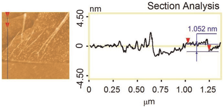
AFM image of rGO.
Compared to the theoretical value, that is, 0.78 nm, it is slightly larger, which may be resulted from the oxygen-containing groups on the rGO surfaces. The root mean square (RMS) is confirmed as 0.366 nm, indicating that this rGO sheet is single-layer graphene since the distance between graphite layers is 0.335 nm.
The rGO flakes were then observed using a scanning electron microscopy (SEM; Hitachi SU-70) as shown in Figure 2 with increased magnifications, in which very thin rGO sheets can be identified.
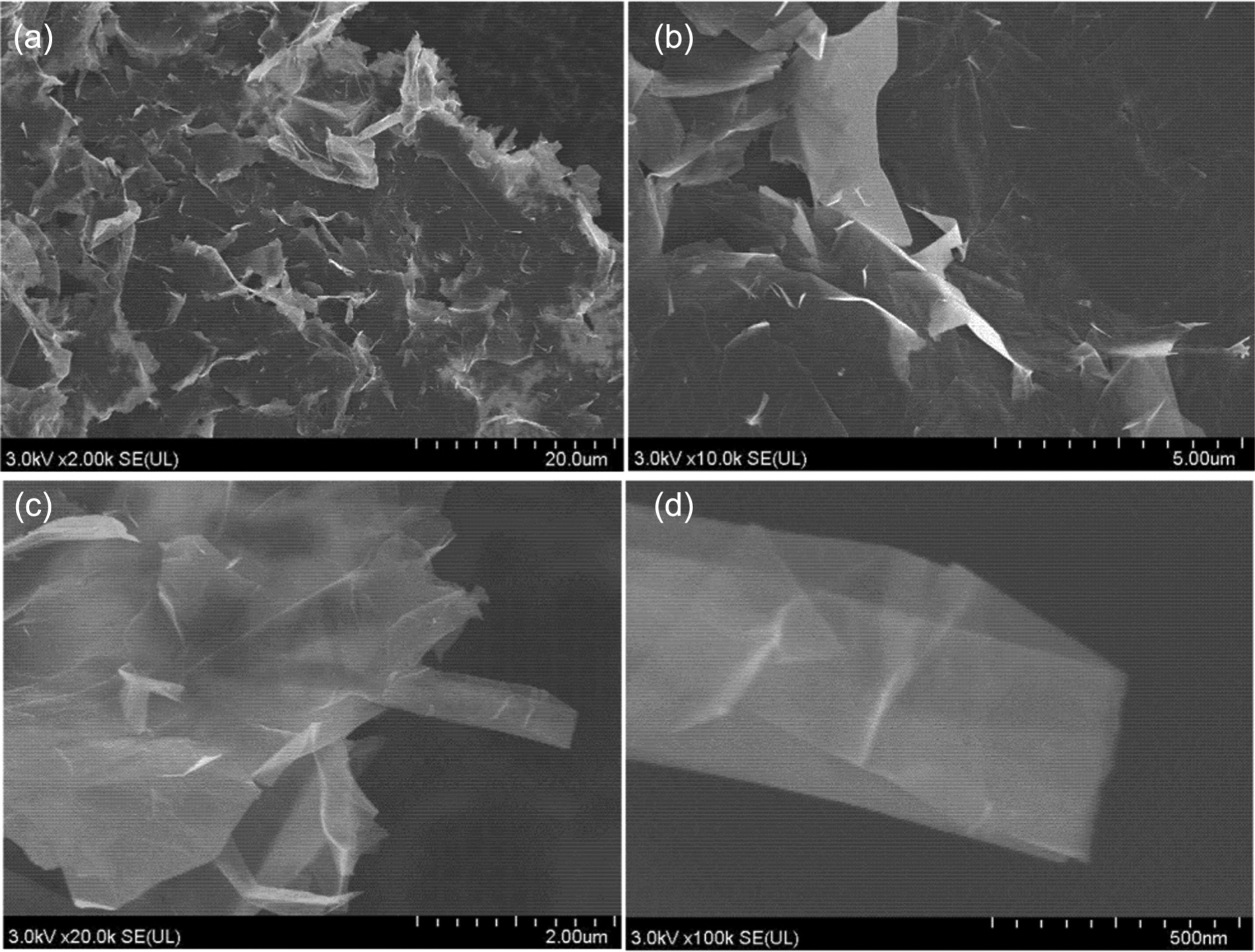
SEM images of rGO with increased magnifications. (a) ×2k, (b) ×10k, (c) ×20k and (d) ×100k
Furthermore, the rGO flakes were characterized by a transmission electron microscopy (TEM; JEOL 100CX instrument) as shown in Figure 3(a). Some rGO flakes are composed of 1–10 individual layers and others may have more layers, approximately up to 50.
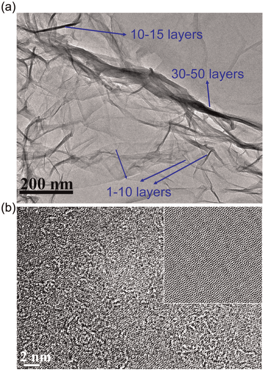
Characterization of rGO by TEM: (a) TEM image of rGO and (b) TEM image of rGO with an inset of FFT image.
To observe the atomic structure of suspended rGO in detail, TEM images (TEM, FEI Titan with Cs-corrector for image) are shown in Figure 3(b) with an inset of fast Fourier transform (FFT) processed image. We can see that the rGO only contains some small ripples and has a very high crystallinity (hexagonal lattice structure).
The PVDF-co-hexafluoropropylene (HFP) was supplied by Arkema Inc., and the dimethylformamide (DMF) was obtained from Wako Pure Chemical Industries, Ltd. The properties of PVDF-HFP are listed in Table 1. It was used as received in experiments.
Properties of PVDF-HFP.
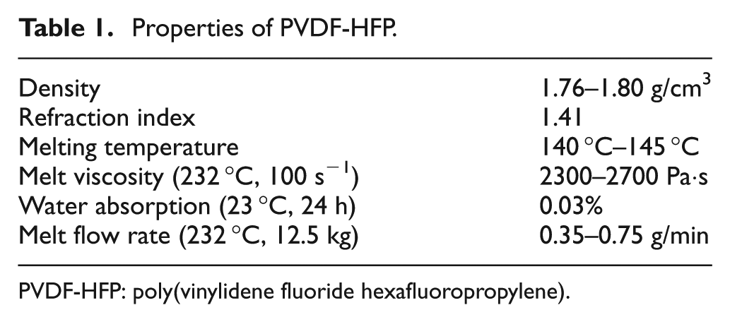
PVDF-HFP: poly(vinylidene fluoride hexafluoropropylene).
Preparation of PVDF/rGO nanocomposite films
The present solution cast method is similar to that reported previously (Wu et al., 2013). The corresponding fabrication process is briefly shown in Figure 4.
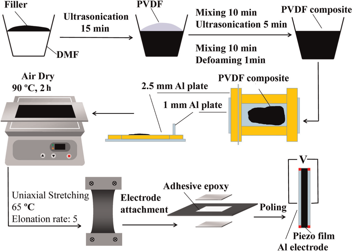
Fabrication process of PVDF/rGO nanocomposite films.
The PVDF/rGO nanocomposite films with different rGO weight content including 0.05, 0.1, and 0.2 wt% were fabricated and notated as PVDF/rGO (0.05), PVDF/rGO (0.1), and PVDF/rGO (0.2), respectively. Moreover, for comparison, the pure PVDF film was also fabricated. The average thicknesses of the obtained films are listed in Table 2.
Average thickness of PVDF/rGO nanocomposite films.
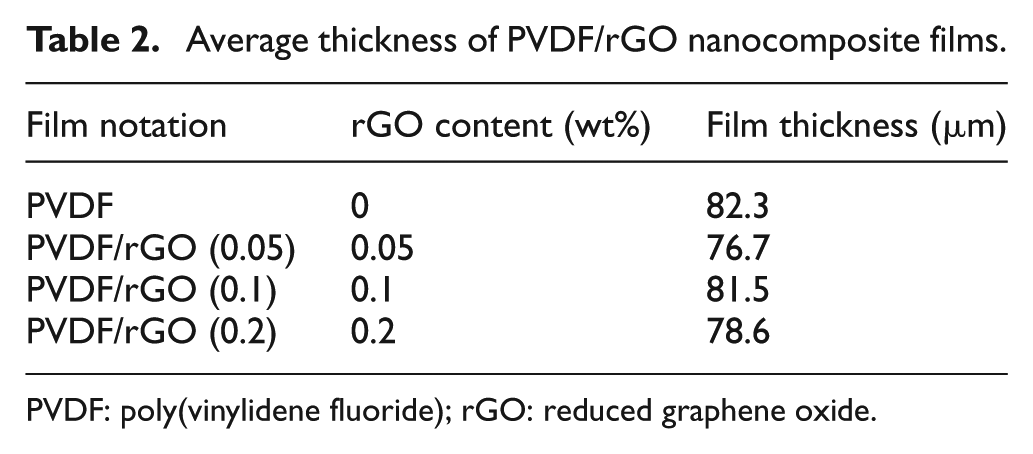
PVDF: poly(vinylidene fluoride); rGO: reduced graphene oxide.
Crystallinity
As the piezoelectricity of PVDF depends on the piezoelectric β-phase, in this study, XRD and FTIR were used to investigate the crystallinity in nanocomposites to confirm the effects of the graphene fillers on the crystal transformation.
XRD was carried out by MPX-3A (X-ray diffractometer; MAC Science Co. Ltd) with CuKα at 40 kV and 30 mA. The angle 2θ ranged from 15 ° to 30 °, the step was 0.02 °, and the scanning speed was 1 °/min.
FTIR was used to further investigate the crystallinity of PVDF/rGO nanocomposite films. In the FTIR spectra analysis, the thickness of the sample was 10 µm. The spectrum ranged from 1000 to 600 cm−1 with a resolution of 4 cm−1 and an aperture of 25 × 100 µm.
Measurements
To evaluate the piezoelectricity of the PVDF nanocomposite films, the open-circuit voltage, the harvested power of alternating current (AC), and direct current (DC) circuits were measured. The measurement setups are illustrated in Figure 5(a) for measuring open-circuit voltage, standard AC circuit (Figure 5(b)), and DC circuit (Figure 5(c)), respectively. Here, the rectifier diode is DX5342 and the capacitance is 33 µF. Note that in the power harvesting experiments, the AC or DC circuit was placed between the piezoelectric film and the oscilloscope in Figure 5(a).
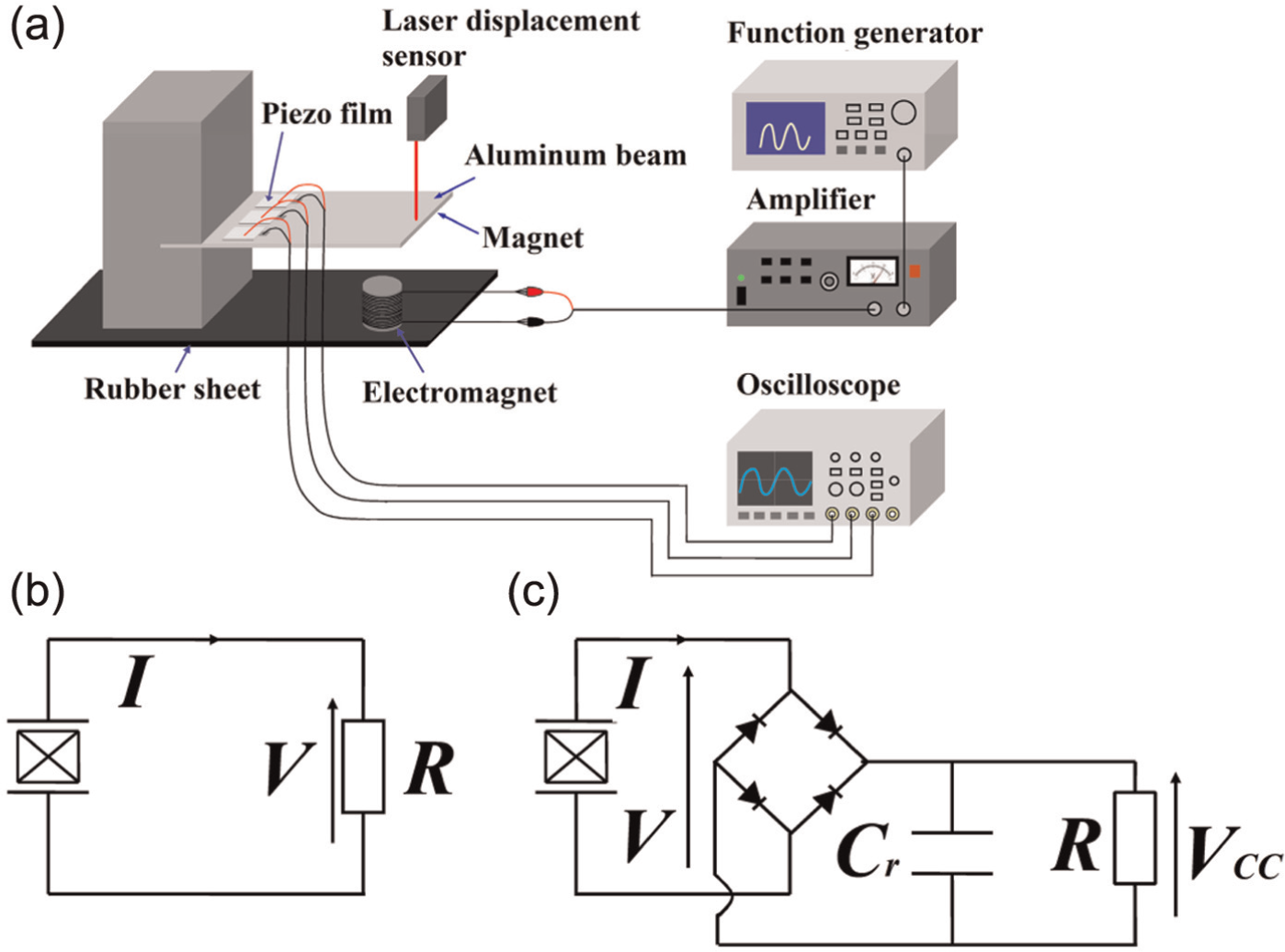
Measurement setups: (a) setup for open-circuit voltage measurements, (b) standard AC circuit, and (c) standard DC circuit.
As shown in Figure 5(a), three pieces of PVDF/rGO nanocomposite films were attached on an Al plate (10 cm × 20 cm × 1 mm) by epoxy resin. The electromagnet was excited with an amplified sinusoidal signal produced by a function generator, which interacted with a permanent magnet attached on the underside of the Al plate (not shown). As a result, the Al plate was vibrated at the same frequency of the sinusoidal signal. To induce the maximum displacement at the free end of Al plate and evaluate the piezoelectricity reasonably, the frequency of the sinusoidal signal was set to be the same with the first natural frequency of the Al plate, that is, around 25 Hz. With the vibration of the Al plate, the length of the films varied periodically. Because of the piezoelectricity of the films, voltage was generated on the two sides of the films and was measured by oscilloscope. The displacement of the free end of the Al plate was measured by a laser sensor. For effective comparison of different films, the tip displacement u of the plate in open-circuit voltage tests was set to 1 mm, while in power harvesting experiment was 1.5 mm. It should be noted that in open-circuit voltage measurement, the three films were independent. However, in power harvesting measurement, they were in parallel.
Results and discussion
Crystallinity
XRD
Figure 6 demonstrates the XRD spectra of the PVDF/rGO nanocomposite films before and after stretching. In Figure 6(a), the peaks at 18.4 °, 20.0 °, and 26.5 °, which correspond to (020), (110), and (021) of the α-form crystallinity (Lee et al., 2008), are observed. Meanwhile, a peak of 20.6 ° (Lee et al., 2008), which corresponds to the (110) of β-crystallinity, does not exist. It indicates that α-phase contents in initial crystallization process are dominant in the PVDF film before stretching. However, the XRD spectra of stretched films are quite different. The peaks related to the α-form nearly disappear and the peaks related to the β-form are clear, indicating that there is an efficient phase transformation during the stretching. Moreover, in Figure 6(b), it is obvious that the relative height of β-phase, that is, hβ, in the films containing 0.05 wt% rGO, is higher than other two samples. Therefore, moderate addition of rGO may improve the stretching effect in phase transformation.
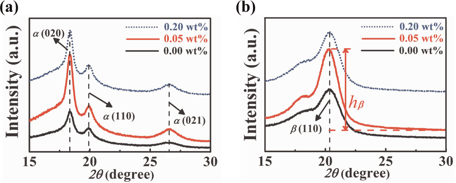
XRD spectra of PVDF/rGO nanocomposite films: (a) before stretching and (b) after stretching.
FTIR
The obtained FTIR spectra of PVDF/rGO nanocomposite films are shown in Figure 7. Before stretching, the peaks of 615, 765, and 975 cm−1 corresponding to the α-form crystallinity (Yu et al., 2009) and the peak of 840 cm−1 corresponding to the β-form crystallinity (Yu et al., 2009) exist as shown in Figure 7(a). However, in the stretched films, the peaks corresponding to β-form crystallinity increase significantly as given in Figure 7(b); in contrast, the peaks corresponding to α-form crystallinity decrease and some peaks even disappear. This transition indicates that after stretching, a majority of α-form has been converted to β-form. In Figure 7(b), in the films containing 0.05 wt% rGO, the peaks corresponding to α-phase decrease most dramatically, especially at 765 cm−1, implying that this content is optimal. This result is consistent with that of the XRD analysis.
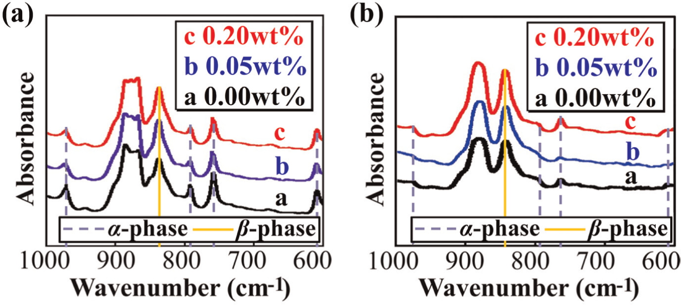
FTIR spectra of PVDF/rGO nanocomposites: (a) before stretching and (b) after stretching.
From the above XRD and FTIR spectra, it is concluded that prior to stretching the films, both α- and β-form crystallinities existed, but α-form dominated in the films. However, after stretching the films, most of the α-form crystals were converted to β-form. As a result, the piezoelectricity was improved due to stretching.
As for the role played by rGO in PVDF phase transformation, it can be clarified from the following four aspects:
In the initial crystallization process, the added rGO works as crystal nucleation agent; more α-phase crystals may be formed easily before stretching, leading to more β-phase crystals after stretching if the transformation rate remains the same. The evidence can be found from Figure 7(a) in which a more obvious peak corresponding to α (021) before stretching can be identified in PVDF/rGO (0.05) film compared to other films.
The phase transformation from α- to β-phase mainly occurs in the stretching process. Uniaxial force leads to the longitudinal deformation of molecular chains and increases the transformation from α- to β-phase (Mohammadi et al., 2007). A possible explanation may be that at a relative high temperature (stretching is applied at about 65 °C), the external force makes the chains more closely packed. As the β-phase cell is of the highest density, it may be the most likely polymorph during the stretching (Jungnickel, 1999). It was also reported that at high temperature, the mobility of chains increases, thus it is easier for the chains to be aligned with the stretching direction. This point was confirmed by the fact that the present films cannot work in 32 mode (3: the thickness direction; 1: the stretching direction; 2: the direction perpendicular to 1 and 3). Meanwhile, the dipole moment of β-chain will be perpendicular to the stretching direction, which contributes the performance of piezoelectricity after poling (Salimi and Yousefi, 2003). In the pure PVDF films, the transformation rate depends on the stress applied on the molecular chains and the stretching ratio. In rGO-contained nanocomposites, the transformation may be further improved by rGO. Similar to CNT, because graphene also possesses carbon atoms of zigzag structure, which matches with the zigzag structure of β-phase, it may enforce the formation of β-phase in spite its conformation is of higher energy compared to α-phase. Moreover, the adsorption energies of α-polymorph and β-polymorph on CNT surface were calculated by Yu et al. (2009) using density function theory (DFT). The adsorption energy difference between these two structures is about 0.2 eV, that is, the released energy of β-polymorphic chain is 0.2 eV higher than that of α-polymorphic chain. As a result, during adsorption, the energy barrier between α-polymorph and β-polymorph may be overcome, and α-polymorphic chain may be transformed into β-polymorph absorbed on the CNT surface. There may be the same process for the interaction between graphene and polymorphic chains. Since graphene is of larger specific surface area, it may affect this transformation more significantly. Moreover, unlike pure polymer, in which the external force is mainly applied on the molecular chains (Sun et al., 2010), in the rGO-contained nanocomposites, the external force may be concentrated on the interface of the chains and the surface of rGO. Thus, this stress concentration may result in higher transformation efficiency around the surface of graphene. This factor affecting the phase transformation may be important. Because graphene is of much larger specific surface area compared to that of CNT, this interfacial stress concentration plays a more significant role, leading to the better piezoelectricity, compared with that of CNT-based PVDF nanocomposites (Wu et al., 2013).
However, too many rGOs hinder the elongation of the macromolecular chain during stretching. Thus, the nanocomposite films with rGO content of 0.1 and 0.2 wt% displayed degraded piezoelectric performance compared to those with lower rGO content. For instance, from Figure 7(b), the relative peak height of β (110), that is, hβ, corresponding to PVDF/rGO (0.05) film after stretching is much larger than that corresponding to PVDF/rGO (0.2) film. Another possible reason may be that the excessive rGO will increase charge accumulation at rGO/β-crystallinity/α-crystallinity interfaces, which results in a depolarization field exceeding the coercive field in nanocomposite films (Kim et al., 2009), and therefore decreases the efficiency of poling process.
Because the phase transformation is almost accomplished in stretching as confirmed by XRD and FTIR, the contribution of poling to phase transformation is limited, especially in PVDF/rGO (0.05) films. The poling mainly plays a role of rearrangement of the dipole moments of β-chain to the direction along the electric field, thus the piezoelectricity can be induced. It is evidenced by the fact that the un-poled PVDF films cannot produce output voltage in the experiments, indicating the random orientation of the dipole moments. Another evidence is that the piezoelectric performance can be enhanced by a higher poling electric field as discussed below.
Open-circuit voltage
The 31 charge generation mode (“3” and “1” indicate the directions of poling and strain, respectively; see Figure 8) of a piezoelectric element is shown in Figure 8.
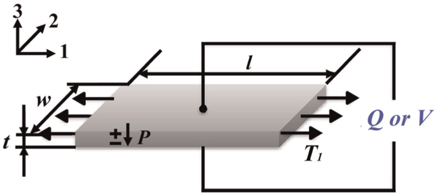
Relation between stress and charge.
The relation between stress
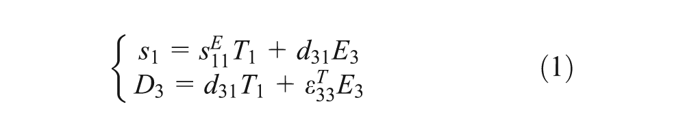
In equation (1),

in which

The open-circuit voltage produced is given as

Here, the following notations are taken:
For periodical voltage, the effective voltage (also called the RMS voltage) is defined as
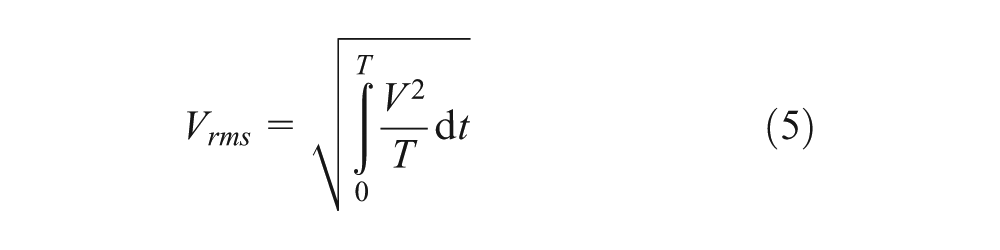
in which
As the thicknesses of films t vary from each other (e.g. Table 2) and the tip displacements u of the free end of the Al plates are also slightly different from each other, for comparison of the open-circuit voltage, the nominal film thickness and tip displacement of Al plate were selected to be
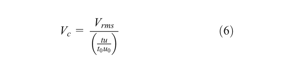
Figure 9 shows the obtained results of the calibrated open-circuit voltage. Note that the first four bars in this figure represent the samples prepared by the poling electric field of 60 MV/m (Wu et al., 2013). Because direct application of such a high electric field for poling may lead to insulation failure, some discontinuous methods were developed (Bauer, 2000; Ng et al., 2000). Here, we adopted one of them, that is, the stepwise method (Wu et al., 2013). It can be seen from Figure 9 that an addition of a small amount of rGO can improve the piezoelectricity significantly. For PVDF/rGO (0.05) with the rGO content of 0.05 wt%, the open-circuit voltage increases to 205% of that for pure PVDF films. However, for PVDF/rGO (0.2), the open-circuit voltage only increases 26% as compared to that of pure PVDF film. It indicates that overdose of rGO will hinder the transformation of PVDF crystal structures from the α- to the β-form and therefore decrease the piezoelectricity of the films. From equation (4), for PVDF/rGO (0.05) films, as
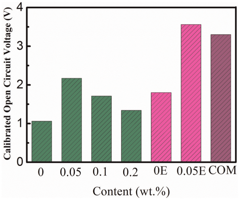
Calibrated open-circuit voltage for PVDF/rGO nanocomposite films.
Power harvesting experiments
The harvested power can be calculated as

in which
The density of harvested power is calculated by

in which
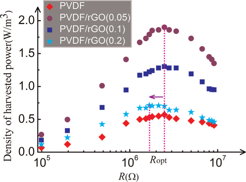
The density of harvested power of AC circuit is shown in Figure 10. From this figure, we can see that the density of the harvested power of the PVDF/rGO (0.05) films is the highest and is about 253% of that of the neat PVDF films. Additionally, the resistance at the optimal density of harvested power (i.e. Ropt) decreases with increase in rGO content.
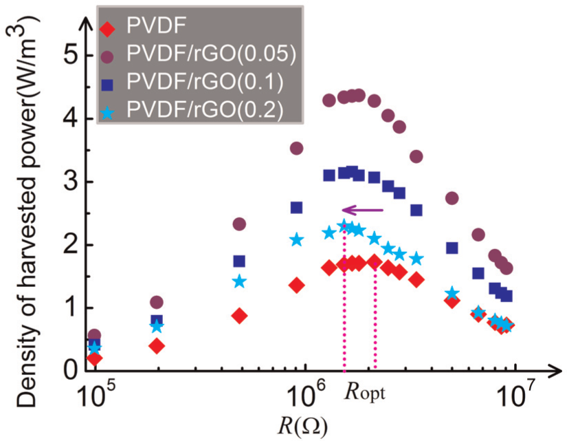
Density of harvested power of AC circuit.
The theoretical model proposed by Guyomar et al. (2005) was used to analyze the increase in the density of harvested power. The output power of a piezoelectric element can be described as
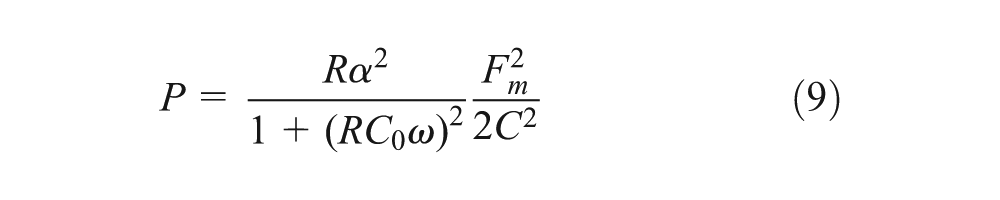
where
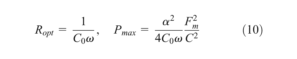
Therefore, the maximum density of harvested power is
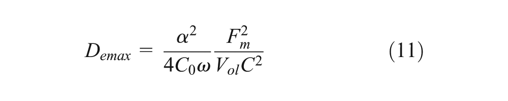
Moreover,
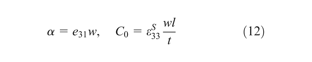
where
By substituting equation (12) into equation (11), the maximum density of harvested power can be rewritten as
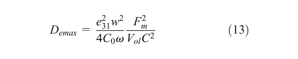
From Figure 10, it can be seen that the resistance at optimal density of harvested power decreases with the increase in rGO content. According to equation (10), the clamped capacitance

where ε is the permittivity,
Dielectric constant of PVDF/rGO composite films.
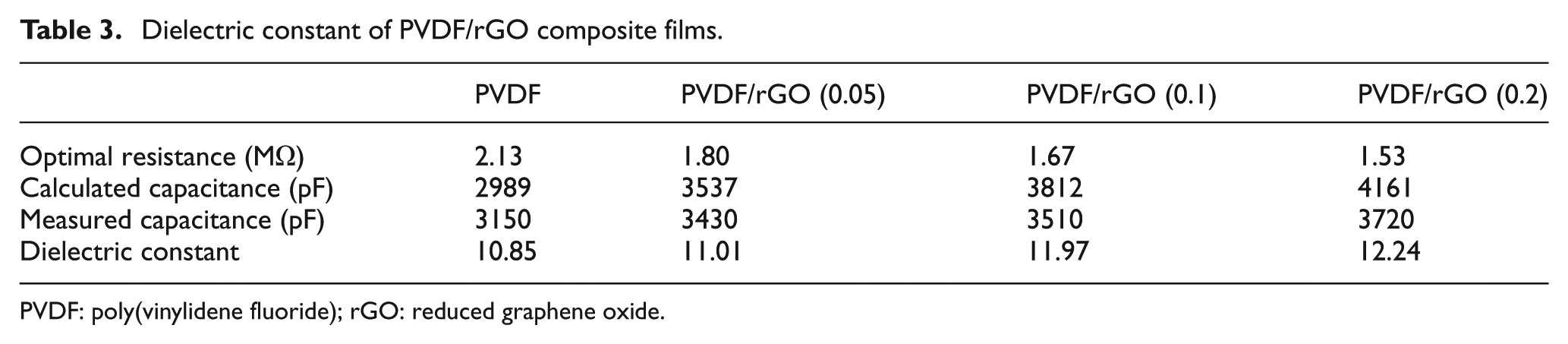
PVDF: poly(vinylidene fluoride); rGO: reduced graphene oxide.
For the PVDF/rGO (0.05) nanocomposite films, maximum density of the harvested power Demax increases. Since Young’s modulus changes slightly at such a low rGO content (Ansari and Giannelis, 2009; Layek et al., 2010) and the external force amplitude Fm and the damping C remain almost the same, according to equation (11), the force factor
Figure 11 shows the density of harvested power collected by the DC circuit. It is found that the density of harvested power of the PVDF/rGO (0.05) films is about 333% of that of PVDF/rGO (0) films. Furthermore, the optimal resistance Ropt of PVDF/rGO (0.2) is lower than that of nanocomposite films with different rGO contents, although the density peak is not so obvious. Since there is a saturation power value for the DC circuit and the harvested power keeps almost in a platform around the saturation power value in a wide range of resistances, the optimal resistance is not obvious.
Density of harvested power of DC circuit.
According to the model proposed by Guyomar et al. (2005), the optimal resistance for DC circuit and the maximum power are
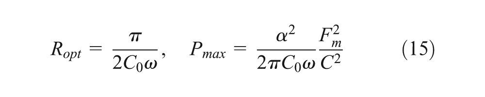
Comparing equation (10) with equation (15), it is concluded that the optimal resistance
Conclusion
PVDF-based nanocomposite films with various contents of rGO (i.e. PVDF/rGO) were prepared, and their piezoelectricity was evaluated by open-circuit voltage test and power harvesting measurements. The results showed that a small addition of rGO can significantly increase the open-circuit voltage and the density of harvested power, due to the improved piezoelectricity of PVDF, indicating the increase in β-phase. Especially at an rGO content of 0.05 wt%, the films performed best. The XRD and FTIR spectra analyses confirmed the nucleation action of rGO in the formation of β-phase crystal in PVDF. It can be concluded that the phase transformation mainly occurs in stretching, while the poling electric field enforces dipole moments aligned along the direction of the electric field. It is also worthy to note that a too high content of rGO will hinder the formation of β-phase crystals because the free space for β-phase elongation and development becomes smaller.
Footnotes
Acknowledgements
This work is partly supported by the Research Funds from National Natural Science Foundation of China (No. 11372104) to NH.
Declaration of conflicting interests
The authors declared no potential conflicts of interest with respect to the research, authorship, and/or publication of this article.
Funding
This research received no specific grant from any funding agency in the public, commercial, or not-for-profit sectors.