
Abstract
This article presents the development of a novel magnetorheological damper which has a self-sensing ability. In this study, a linear variable differential sensor, which was based on the electromagnetic induction mechanism, was integrated with a conventional magnetorheological damper. The working principle, configuration, and prototype of the displacement differential self-induced magnetorheological damper based on the integrated linear variable differential sensor technology were presented. A mathematical model of the proposed displacement differential self-induced magnetorheological damper was established. The finite element model was built with two-dimensional Maxwell software and the magnetic simulations were presented. With this approach, the influence of the flux leakage, the winding cylinder in different basic values of structure parameters, and materials were determined to obtain an optimal displacement differential self-induced magnetorheological damper. Finally, the dynamic performance of the displacement differential self-induced magnetorheological damper was evaluated with a fatigue test machine. The experimental results indicated that the developed displacement differential self-induced magnetorheological damper based on the integrated linear variable differential sensor technology can output controllable damping force and displacement relative self-induced voltages simultaneously.
Keywords
Introduction
Magnetorheological fluid (MRF) is a smart material invented by Rabinow (1948) in the middle of the 20th century. It can transform from a free-flowing state to a semi-solid state in milliseconds when an external magnetic field is applied. This behavior is called an MR effect, which is a reversible and rapid effect. The MR effect depends mainly on the magnetic field intensity rather than outside temperature or impurities in fluids (Bossis et al., 2002; Jolly et al., 1999). MRF has well been used to develop a variety of intelligent devices, such as MR dampers and MR clutches (Li et al., 2009; Yao et al., 2002; Yoo and Wereley, 2004; Zhu et al., 2012), which have been used in civil structure, bridge structure, vehicle suspension, automobile clutch, and so on (Gordaninejad et al., 2002; Lee and Choi, 2000; Li et al., 2007; Yu et al., 2009).
A schematic diagram of a magnetorheological damper (MRD) semi-active control system on mechanical structures is shown in Figure 1, which consists of several key components, such as MRD, sensors, mechanical structure, vibration force, and control strategies. To effectively reduce the influence of vibration force on mechanical structures, the MRD semi-active control system chooses a closed-loop control to mechanical structures through the changing of controllable damping force under a direct current (DC) generated by the controller system according to the signal of force sensor and the response of displacement sensor. In order to simplify the structure of the MRD semi-active control system, reduce the cost of daily maintenance, improve the reliability of operation, and decrease the installation spaces, an innovative approach integrated with a self-induced structure into MRD has been developed by a number of groups. The MRD with integrated self-induced structure could take the place of the traditional MRD with displacement sensor in semi-active control system on mechanical structures.
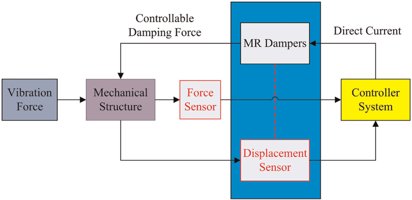
Schematic diagram of MRD semi-active control system structures.
Chen and Liao (2012) invented a self-powered and self-sensing MR damper which integrated a power part and sensor part. However, the complex structure and difficult installation make it hard to find practical applications. Wang and his coworkers proposed a novel modeling of integrated displacement self-sensing MR damper (Wang and Bai, 2011; Wang et al., 2010; Wang and Wang, 2009). Although the modeling was able to generate self-sensing voltages, the magnetic circuit is unstable to pass through the upper lid, and the reluctance of the whole circuit is variable which makes the self-sensing voltages to have theoretical deviation with true value. Additionally, the integration could degrade the performance of both sensing and damping capabilities. In their study, the Pareto optimization method was used to handle the trade-off between the damping force and the sensing performance. Wang et al. (2009) presented a new self-powered and sensing semi-active control system based on MR damper. The numerical simulation results showed that the two self-powered control strategies could get close performance with its corresponding semi-active control with external power supply. Lam et al. (2010) developed an MR damper with dual-sensing capability by integrating a piezoelectric force sensor and a displacement transducer with a conventional actuation-only MR damper. The experimental results showed that the MR damper with embedded force and displacement sensors had advantages in fulfilling real-time closed-loop feedback control applications for mitigating structural vibrations in a reliable and simple manner. Choi and Wereley (2009) studied the feasibility and effectiveness of a self-powered MR damper using a spring–mass electromagnetic induction device. Sapinski proposed a semi-active vibration control system comprising the EMI prototype and the damper RD 1005-3 and employed an electromagnetic transduction mechanism to extract energy from vibrations. The experiments demonstrated that the proposed system was able to supply power to the MR damper, and the EMI acted as a “velocity-sign” sensor (Sapinski, 2011). Nehl et al. (1996) developed an integrated relative velocity sensor that integrated into a liquid damper. The integrated relative velocity works under the static magnetic field and outputs self-induced voltages dependent on velocity. The integrated plan above cannot be used into MR damper because the self-induced static magnetic field would affect the performance of damper seriously. We also proposed a self-sensing MR damper, whose performance was evaluated with simulation analysis (Peng et al., 2011). However, the accuracy of the self-sensing ability needs to be improved.
In this study, we extended our work in developing and prototyping a displacement differential self-induced magnetorheological damper (D-DSMRD) by integrating a linear variable differential sensor into an MRD for realizing a new functional MR damper that has the self-induced ability. This article is organized as follows. First, the working principle of the D-DSMRD is presented. The finite element model was then built with two-dimensional (2D) Maxwell software, and the magnetic simulations were also discussed. Finally, the dynamic performance of the developed D-DSMRD was experimentally evaluated.
Principle and configuration of the D-DSMRD
Structure of the D-DSMRD
In this study, a mixed mode combining both a flow mode and a direct-shear mode is chosen to design the proposed D-DSMRD. In this design, as shown in Figure 2, an inner cylinder space is divided into two pressure chambers by a piston, where the MRF flows through the gap between the magnetize regions and the outer cover from the high-pressure chamber to the low-pressure chamber. A magnetic circuit, formed by the excitation coil wound on the piston, is used to generate controllable magnetic field by varying the coil current. As shown in Figure 2, the MRF in the magnetic field of primary flux was magnetized based on the MR effect, which would output shear damping forces and valve damping forces. The resultant damping forces vary dynamically with the magnetic field generated by the excitation coil which input the DC.
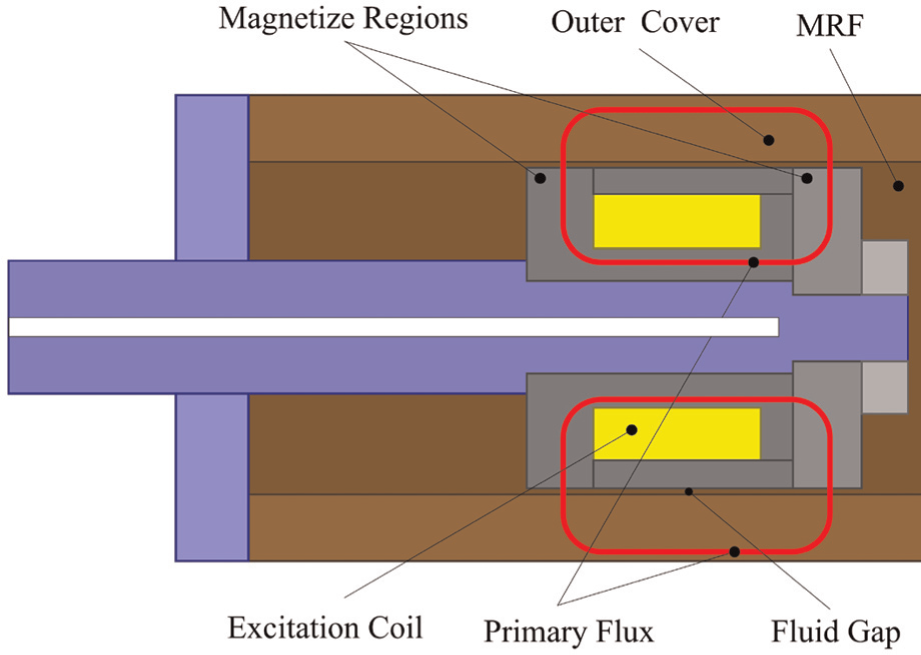
Principle diagram of flow mode and direct-shear mode of MRD.
The detailed structure of the proposed D-DSMRD is shown in Figure 3(a). It consists of a piston head that wound excitation coils, a winding cylinder that wound differential coils, and an outer cover. Specifically, the coil wound on a piston head acting as an excitation coil and providing magnetic fields to both integrated linear variable differential sensor (ILVDS) and MR fluids simultaneously, while differential coils wound on the winding cylinder to generate electromotive forces and output self-induced voltages. The piston head can input alternating currents (ACs) in different frequencies and DCs at the same time. The magnetic field generated by the AC enables differential coils to produce self-induced voltages, while the magnetic field generated by the DC magnetizes the MRF in the annular channel. The input voltage is through hollow on the piston rod, and the output self-induced voltage is through the hollow on the outer cover.
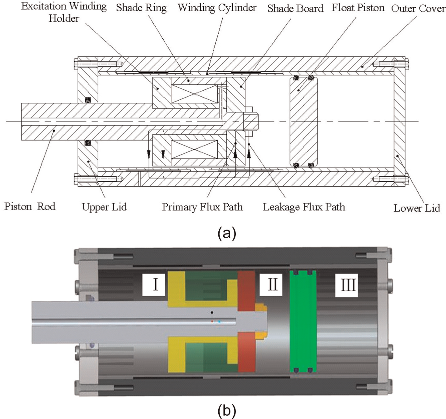
Structure of D-DSMRD: (a) CAD structure (b) Pro/E structure.
Similar to the traditional mixed mode that is shown in Figure 2, the working magnetic circuit of the proposed D-DSMRD is shown in Figure 3(a), which has a leakage flux path, denoted by black lines with arrow, appearing nearby the primary magnetic path. A non-magnetic metal (stainless steel) was used to fabricate the piston rod, the winding cylinder, shade ring, the upper lid, and the lower lid to avoid the magnetic circuit passing through, while a magnetic metal (10# steel) was used to fabricate the piston, the shade board, and the outer cover to generate a closed-loop working magnetic circuit. The output MRD damping force generally consists of two parts: the shear damping force and the valve damping forces, which are generated by shearing MR fluids in the gap by the difference in pressures of two chambers, respectively.
Controllable damping force of the D-DSMRD
Based on the Bingham constitutive relation, the output damping force Fsv is represented as
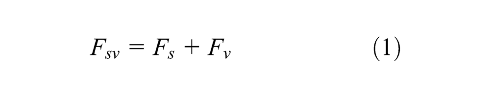
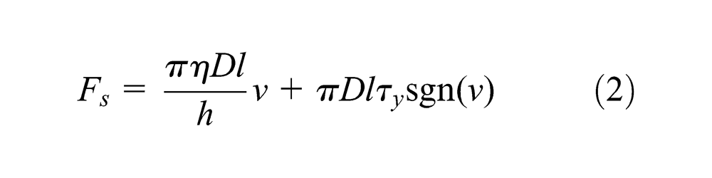
where Fs is the direct-shear damping force, given by
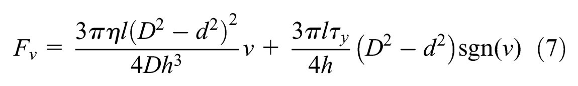
And the valve damping force Fv is represented as
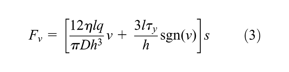
where η is the viscosity of MR fluids, l is the length of effective magnetic fields, s is the effective regional area, q is the volume flow of MRF, D is the diameter of piston head, d is the diameter of piston rod, h is the thickness of fluid gap, v is the velocity of piston, and τy is the shear yield strength of MR fluids.
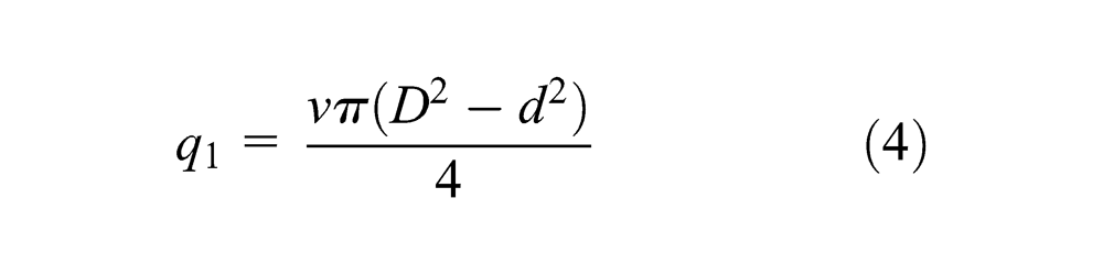
As shown in Figure 3(b), the whole chamber is composed of the upper lid, the winding cylinder, and the lower lid. The whole structure of the D-DSMRD is divided into three parts, that is, I, II, and III, by the piston and the float piston. The MRF in parts I and II flows from high one to another, and air in part III is extruded or compressed. The pressures in these three parts depend on whether the fluid is in tensile or compression stage.
In the tensile stage, the pressure of part I is higher than others, and MRF in the MRD flows out from part I to part II; the volume flow at the tensile stage is given by
In the compression stage, parts II and III are compressed by the piston, while part I is extruded; MRF in the MRD flows out from part II to part I; the volume flow at the compression stage is
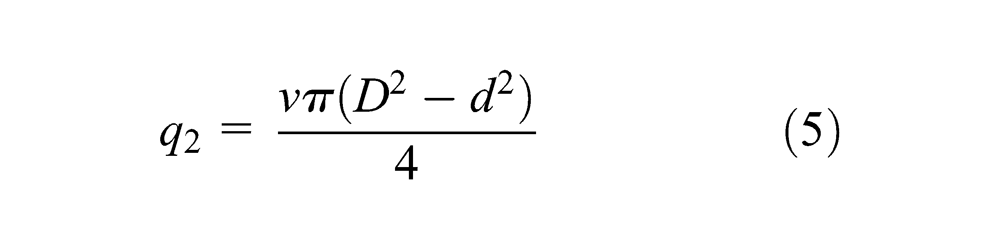
Because the volume flow of tensile stage is equal to the volume flow of compression stage, the effective area of part I is given by
So, the valve damping force of the D-DSMRD is given by
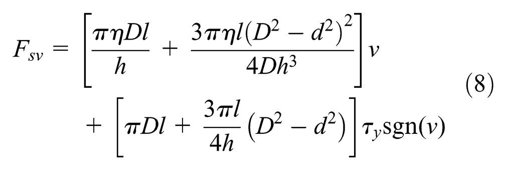
From equations (3) and (7), the whole output damping force is given by
Principle of differential self-induced technology for the D-DSMRD
The key technology for differential self-induced ability in the D-DSMRD is an ILVDS method based on the electromagnetic induction. To save the installation space and maintain functions, the D-DSMRD structure reusing the excitation coil is wound on the piston as the exciting coil for the ILVDS, the self-induced coils are wound on the winding cylinder inside the outer cover, and the AC is input to the excitation coil to generate alternating magnetic field for ILVDS. The structure of the ILVDS in the D-DSMRD is shown in Figure 4, and the circuit diagram of ILVDS is shown in Figure 5. As shown in Figure 4, the D-DSMRD has the excitation coil wound on the piston (yellow color), the two differential self-induced coils for ILVDS wound on winding cylinder, the primary flux of self-induced magnetic path is shown as the curve in red color, and the leakage flux of self-induced magnetic path is shown as the curve in green color. The magnetic circuit of ILVDS is the same as the magnetic circuit of MRD damping force. To build the D-DSMRD with ILVDS, the self-induced magnetic circuit is ensured not to disturb the damping force magnetic circuit, and the leakage flux should be as small as possible.
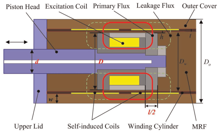
Principle diagram of D-DSMRD.
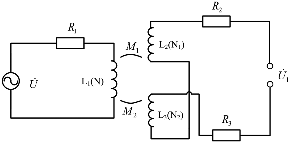
Circuit diagram of differential self-induced technology.
The turn of the excitation coil in Figure 4 is denoted as N, and the turn of excitation coils is denoted as N1 and N2 in Figure 5.
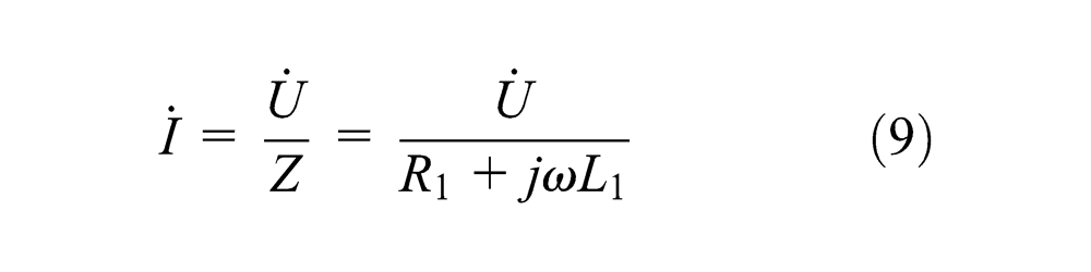
The AC in excitation coils is given by
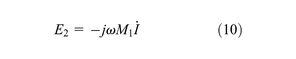
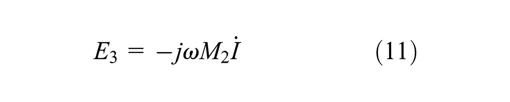
The electromotive forces of differential-induced coils are given by
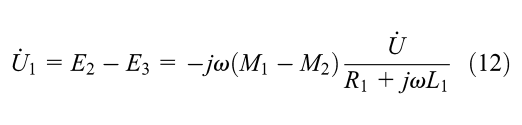
The output differential-induced voltage is
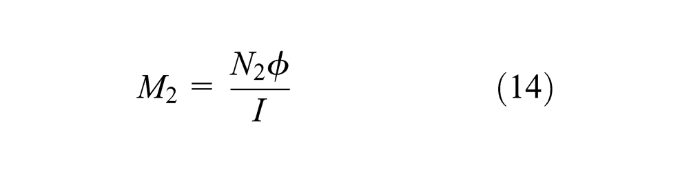
The mutual inductances of differential-induced coils are

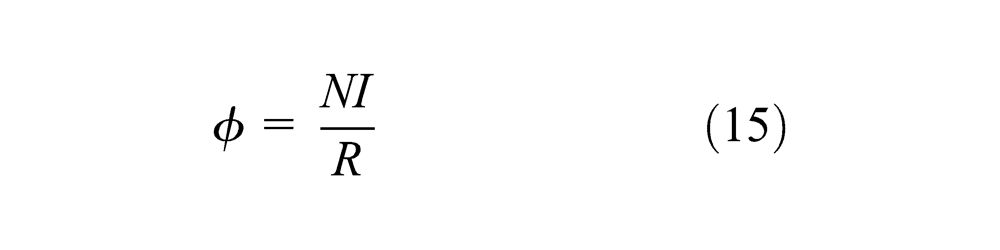
The magnetic flux in induced coils is
The reluctance of magnetic circuit is
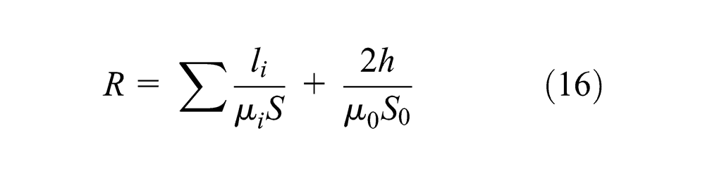
where li is the length of the conductor in magnetic circuit, µi is the permeability of each section, µ0 is the permeability of vacuum, h is the thickness of air gap, and S0 is the area of the air cross section. The self-inductance of excitation coils is defined as
Because of the
where ΔN is the change in N1 and N2, which is due to the movement of piston head, and it is given by

where ΔSp is the change in differential-induced coils of areas
where Δl is the relative displacement of piston head and hc is the thickness of turns of the induced coils. Because the other parameters are constants, the output self-induced voltage
Model and simulation of the D-DSMRD with finite element model
In this section, a 2D finite element model of D-DSMRD was built with the Maxwell 14.0 software as shown in Figure 6(a); the finite element model after meshing operation is shown in Figure 6(b). Because the finite element model is axisymmetric by the y-axis, the performances of the D-DSMRD model in each sides of y-axis are the same. As shown in Figure 6(a), this model has three material property areas as follows: (1) magnetic metal areas denoted as 1008 steel and copper provided by local database, such as excitation winding holder, shade ring, shade board, and coils; (2) non-magnetic metal areas denoted as stainless steel searching in local database, such as upper lid, lower lid, piston rod, winding cylinder, and float piston; and (3) MRF material which is defined by nonlinear B-H curve. After assigning the material areas of each parts of model, the 1.5 A current of excitation coils was set, the boundary of structures was provided, and the rules of simulation were also set. By finishing the preparation above, the simulation results are as shown in Figure 7.
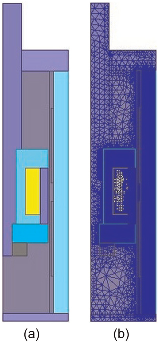
Two-dimensional finite element model of the D-DSMRD based on two-dimensional Maxwell software: (a) entity model and (b) finite element model.
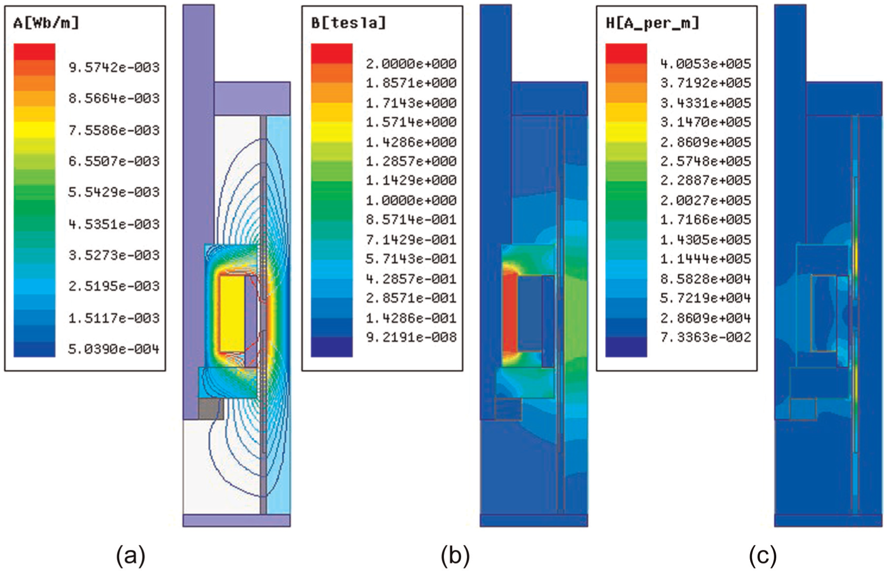
Magnetic simulation of the D-DSMRD: (a) flux path, (b) magnetic induction intensity, and (c) magnetic field intensity.
Figure 7(a) shows the flux path of piston in D-DSMRD; Figure 7(b) shows the magnetic induction intensity of D-DSMRD; and Figure 7(c) shows the magnetic field intensity of D-DSMRD. From Figure 7(a), it can be seen that low level of flux leakage path appeared on the upside and downside of piston, and high level of flux path appeared in the piston. As shown in Figure 7(b), the highest magnetic flux density (from 1.85 to 2 T, red color area) was in the inner piston; the two sides of the piston and the inner parts of the outer cover have magnetic flux density ranging from 0.85 to 1.4 T (green color area), and other parts (blue color areas) have the low flux densities (0–0.14 T). From the magnetic simulation results in Figure 7(b) and (c), the high-level magnetic induction intensity appeared in the MRF gap, which would well magnetize working MRF.
Magnetic flux leakage reduces the MRD performance, which should be taken into account for optimizing the damper performance. In this study, four finite element models were built, as shown in Figure 8(a) to (d). The first model is a traditional MRD without self-induced function; the second model is the D-DSMRD with magnetic metal material (10# steel) winding cylinder; the third model is the D-DSMRD with non-magnetic metal material (stainless steel) winding cylinder; and the fourth model is the D-DSMRD with other kinds of non-magnetic metal material (aluminum) winding cylinder. From the simulation results of the four models given above, the model of traditional MRD without winding cylinder has more concentrated flux path than the D-DSMRD model which has a winding cylinder. The model with a winding cylinder, which was made by a magnetic metal, such as 10# steel, has more concentrated flux path than the one made by non-magnetic metals.
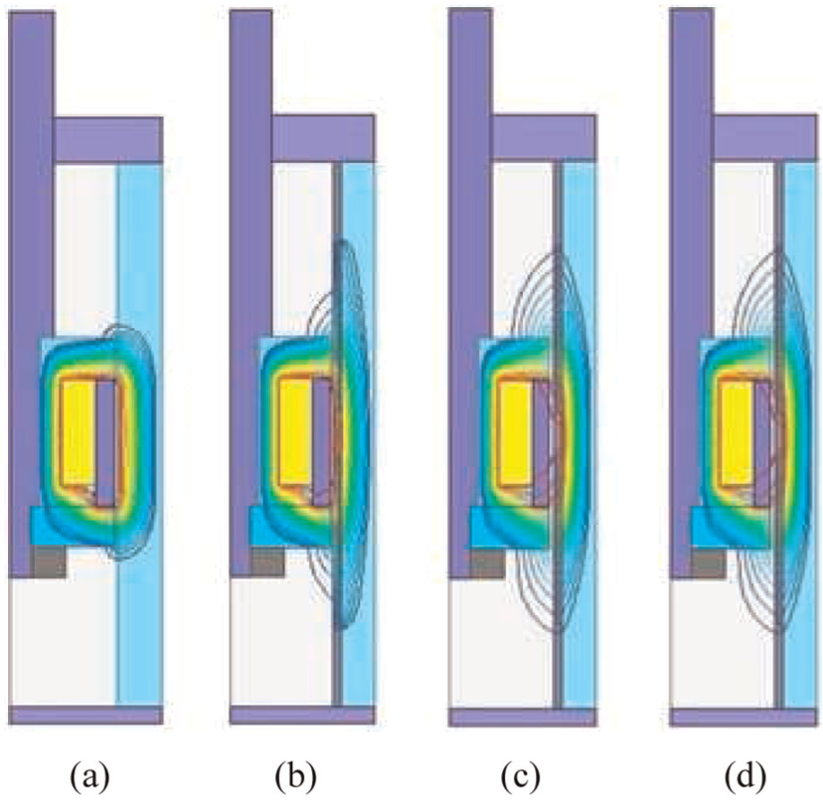
Leakage flux of different models: (a) none winding cylinder, (b) 10# steel winding cylinder, (c) stainless steel winding cylinder, and (d) aluminum winding cylinder.
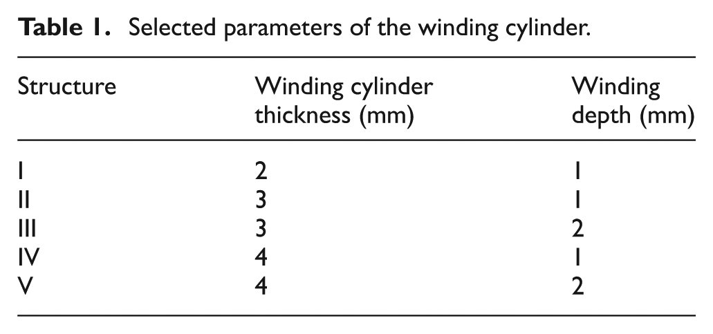
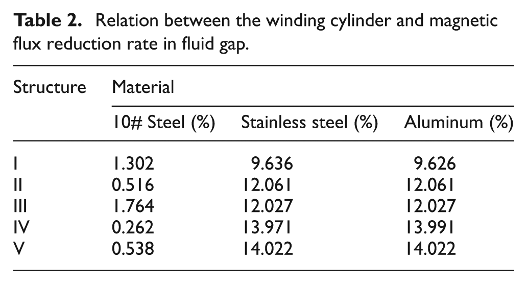
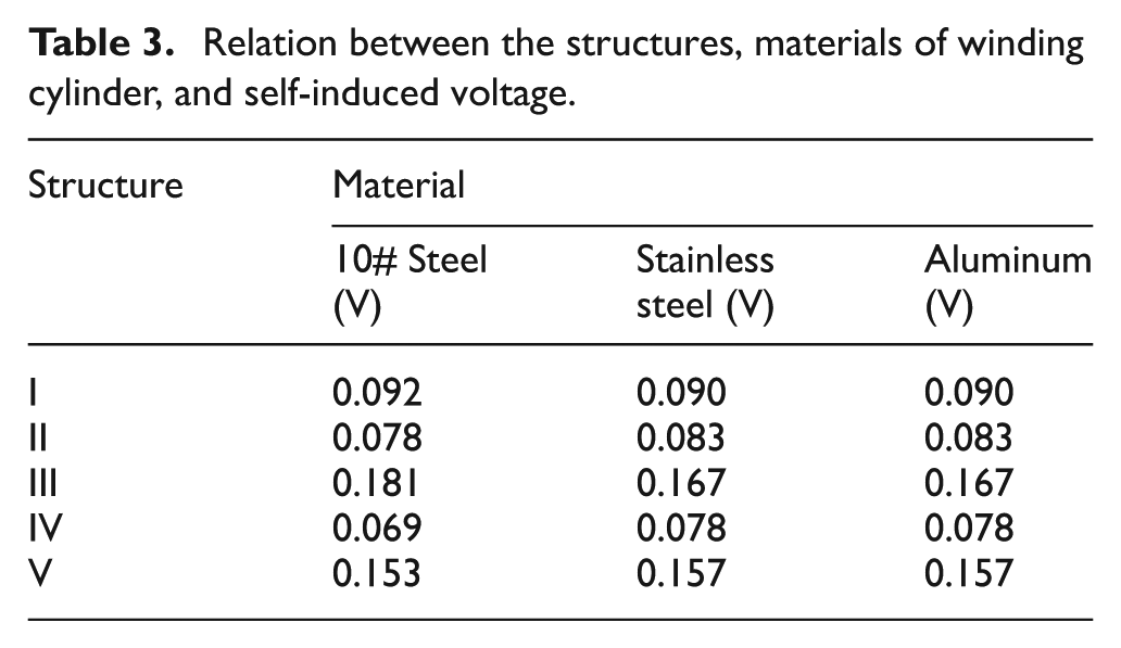
The schematic of the winding cylinder in D-DSMRD is shown in Figure 9. The symbol h denotes the thickness of winding cylinder, and the symbol a denotes the winding depth. Two winding regions I and III are divided by area II. In order to detect the relationship between the flux leakage and structure parameters and materials of winding cylinder, five D-DSMRD models of different structures and three D-DSMRD models of different materials were built. The selected parameters, which include three thicknesses and two winding depths, of the winding cylinder model are listed in Table 1. The flux reduction rate comparisons are shown in Table 2, and the self-induced voltage comparisons are shown in Table 3.
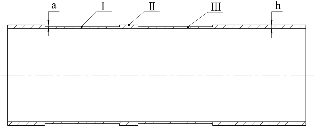
Schematic of the winding cylinder for D-DSMRD.
Selected parameters of the winding cylinder.
Relation between the winding cylinder and magnetic flux reduction rate in fluid gap.
Relation between the structures, materials of winding cylinder, and self-induced voltage.
As shown in Table 2, the flux reduction rates of 10# steel are much lower than others, while the flux reduction rates of stainless steel are almost the same as the aluminum ones, which means that the magnetic metal winding cylinder would produce more concentration flux and lower flux reduction rate than non-magnetic metal winding cylinders. By comparing the flux reduction rate in 10# steel structures, the reduction rate I was 1.302% and lower than III but higher than others. The flux reduction rate II was 0.516%, which was lower than the other reduction rates among structures IV and V. By comparing the flux reduction rate in stainless steel structures, the reduction rate I was 9.636%, which was the lowest of other three structures; and the flux reduction rate of structure II was close to the flux reduction rate of structure III.
As shown in Tables 2 and 3, in the 10# steel model, more winding depth will produce more flux leakage and generate more self-induced voltages by holding more turns of self-induced coils; more winding cylinder thickness would reduce self-induced voltages. In stainless steel model, more winding depth will produce more flux leakage and generate more self-induced voltages; more winding cylinder thickness would decrease self-induced voltages. In the aluminum model, the simulation results are the same as the stainless steel model.
From the simulation results above, the thick winding cylinder has higher flux reduction rate than the thin winding cylinder. Thus, the way to optimize the magnetic circuit of D-DSMRD damper was choosing the thin thickness winding cylinder of non-magnetic material (stainless steel).
Prototype of the D-DSMRD
The dimensions of the developed D-DSMRD are listed in Table 4. The photographs of parts, partial assemble, and prototype of the D-DSMRD are shown in Figure 10(a) to (c), respectively.
Basic values of the structure parameters for the D-DSMRD.

D-DSMRD: displacement differential self-induced magnetorheological damper.
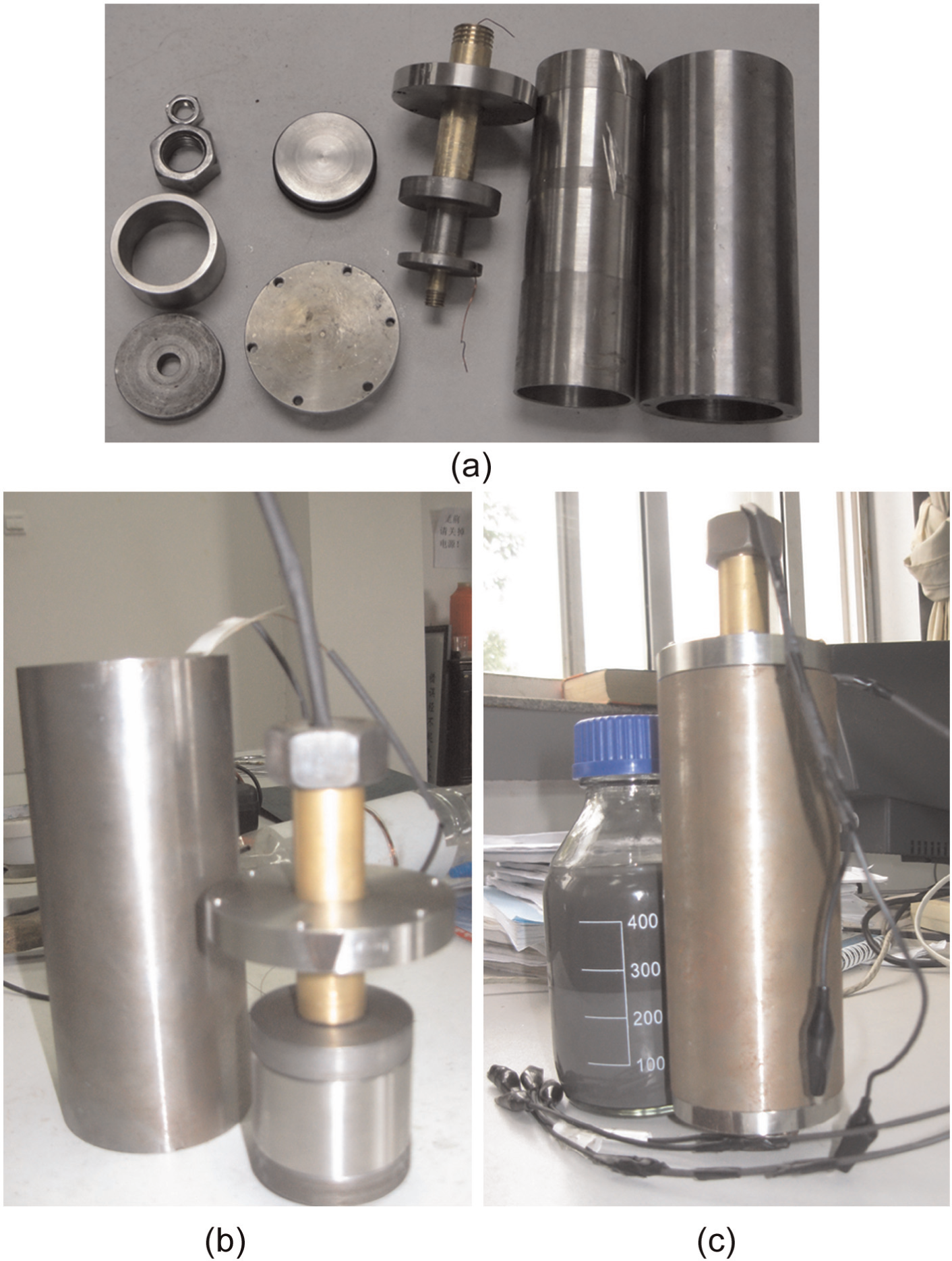
Assembly and prototype of the D-DSMRD: (a) parts of the D-DSMRD, (b) partial assemble of the D-DSMRD, and (c) prototype of the D-DSMRD.
Experimental evaluation of the D-DSMRD
Sensor performance characteristics
In order to acquire the self-induced voltages generated from movement of piston rod, both a signal acquiring module and an analysis module were built by LabVIEW software, which is shown in Figure 11(a) and (b), respectively. By using the signal acquiring module, the self-induced voltage amplitude and power spectrum can be shown on waveform graphs, where the amplitude of voltages can be adjusted by a knob. The signal data were written into the “.lvm” documents by entering the press of “save graph,” and the waveform documents can be opened by the analysis module. Additionally, the waveform data can be analyzed, printed, and saved as *.xls documents or *.jpg documents.
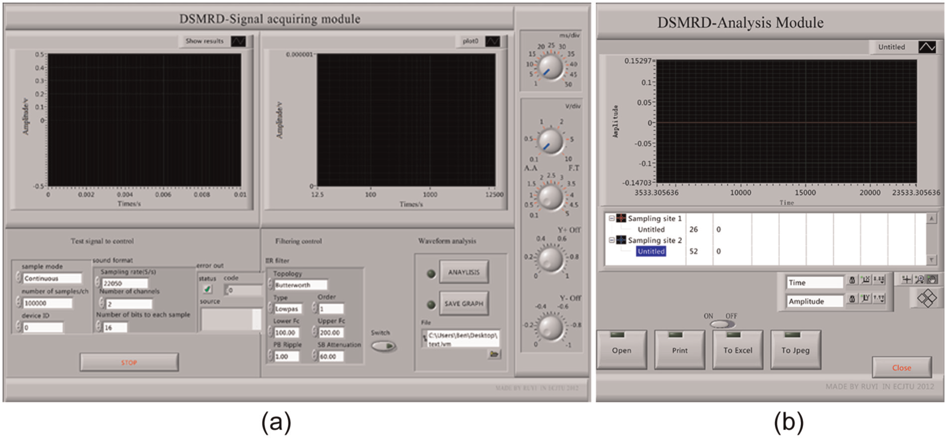
Front panel of (a) signal acquiring and (b) analysis module.
The photograph of the experimental setup for testing the prototyped D-DSMRD is shown in Figure 12. The AC excitation voltage was supported by SET-998+ experimental instrument, and the differential coils were connected to the data input port of audio card.
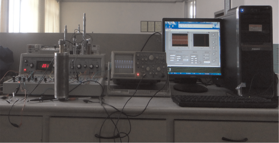
Self-induced testing plan of D-DSMRD in static state.
Self-induced voltages under three positions
With the frequency of 1 kHz and amplitude of 0.84 V of sinusoidal excitation, a random position was chosen and denoted as position 1, the distance from position 1 to 2 is 10 mm, and the distance from position 2 to 3 is 10 mm. The self-induced voltages of testing results in three positions are shown in Figure 13. Figure 13(a) to (c) shows the D-DSMRD self-induced voltage waveform during positions 1 to 2, which indicate that the self-induced voltage has a clear increase when the piston rod moves. Figure 13(d) to (f) shows the differential self-induced voltage waveform during positions 2 to 3. The self-induced voltages have the same trends as positions 1 to 2, and the waveform also has little distortions.
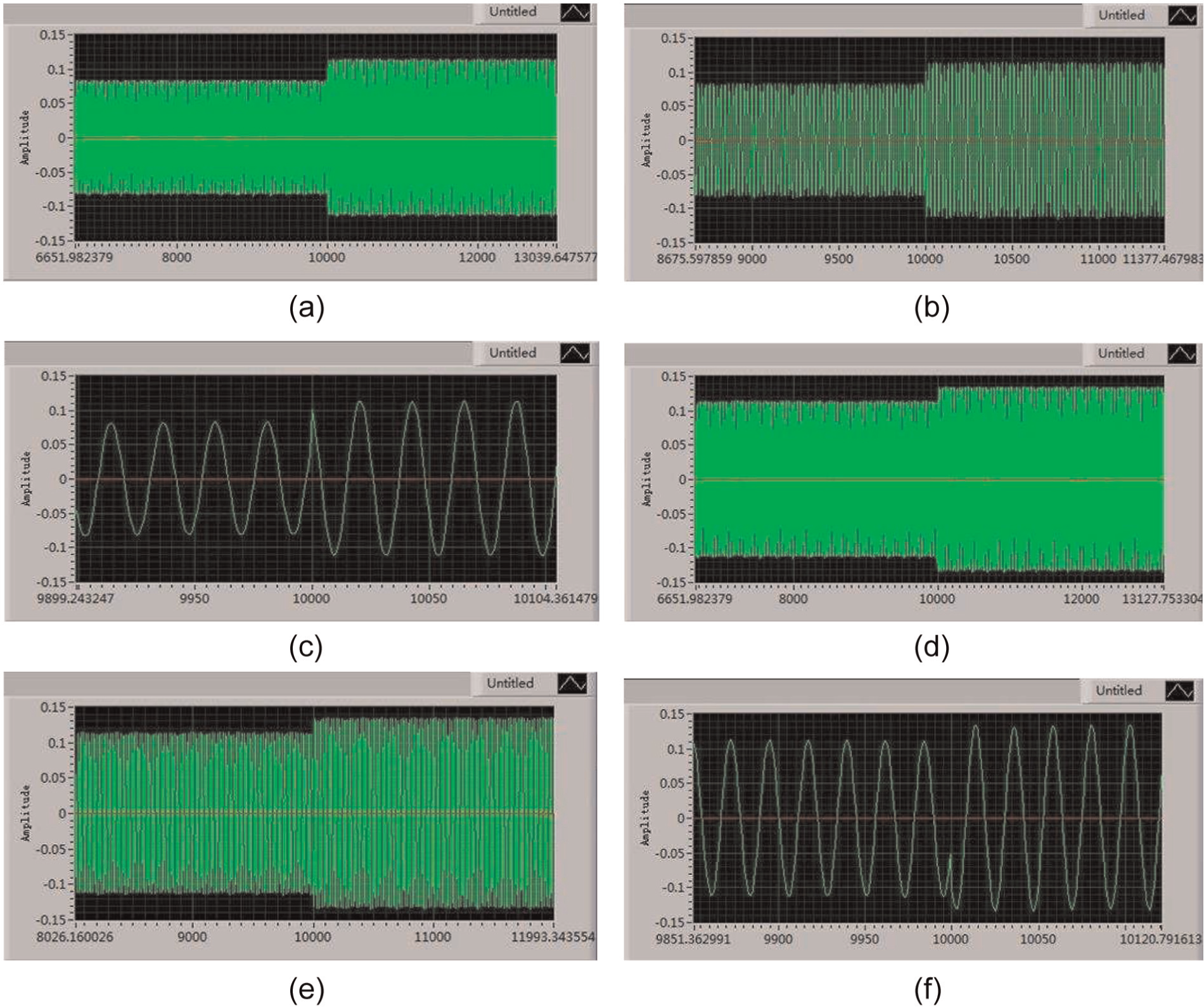
Self-induced voltages in three positions: (a) the waveform of self-induced voltage from positions 1 to 2, (b) the interception waveform of positions 1 to 2 after enlarged x-axis, (c) the local waveform of 1 to 2 fully enlarged, (d) the waveform of self-induced voltage from position 2 to position 3, (e) the interception waveform of 2 to 3 after enlarged x-axis, and (f) the local waveform of 2 to 3 fully enlarged.
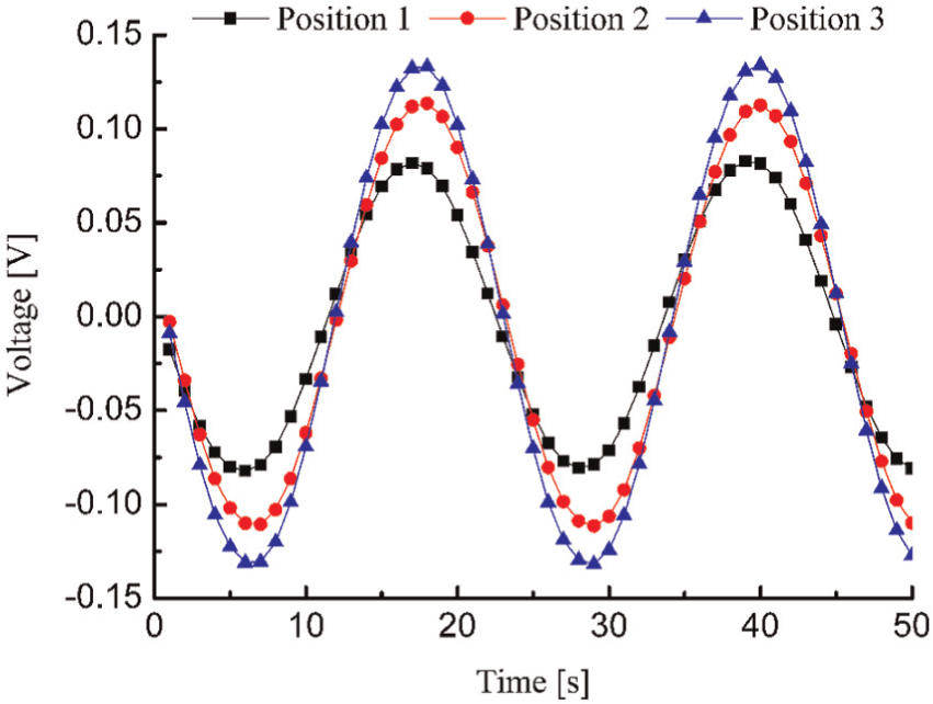
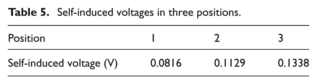
Figure 14 shows the self-induced voltages at three positions, where the black color denotes the voltage in position 1; the red color denotes the voltage in position 2; and the blue color denotes the voltage in position 3. The peak values of the self-induced voltages at these three positions are summarized in Table 5. Though the distance of positions 1 to 2 and the distance of positions 2 to 3 were both set as 10 mm, the self-induced voltage drop from position 1 to position 2 is not the same as that from position 2 to position 3. The deviation might be due to the possible errors such as fabrication error and measurement error. Because of the fabrication error, the winding depths of the two winding areas are not the same, and the turns of each section in two areas are not exactly the same. Because of the measurement error, the real distances of each position are not exactly the same as well. To reduce the deviation, higher processing accuracy and measurement accuracy should be guaranteed in the next experiment.
Comparison of D-DSMRD self-induced voltages.
Self-induced voltages in three positions.
Self-induced voltages under different DC inputs for the excitation coil
Figure 15 shows the self-induced voltage under different DC inputs for the excitation coil. The testing frequency is 1 Hz and the damper displacement is set from −7.5 to+7.5 mm, which is provided by the fatigue test machine. The alternating voltage value is 6.0 V and the frequency is 1 kHz. From Figure 15, it can be seen that the maximum self-induced voltage basically remains unchanged though the DC inputs for the excitation coil increased from 0.25 to 0.75 A. Specifically, the maximum self-induced voltages are 0.158, 0.156, and 0.159 V when the DC inputs are 0.25, 0.50, and 0.75 A, respectively. The deviation is within 2%. Thus, it is concluded that the DC input has little influence on the output of the self-induced voltage.
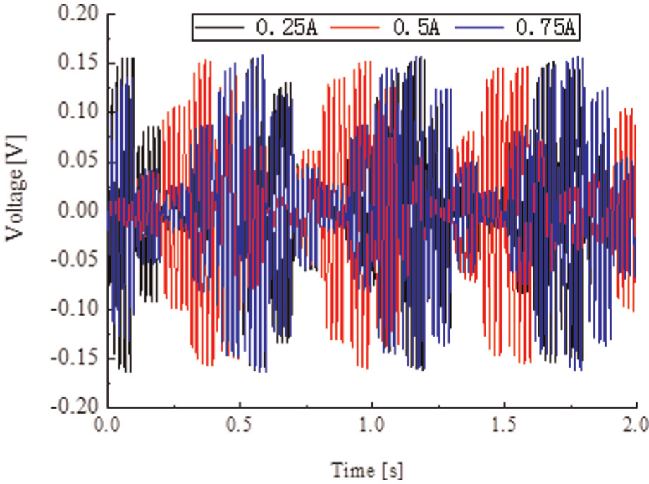
Self-induced voltage under different direct current inputs for the excitation coil as the damper displacement is set from −7.5 to+7.5 mm.
Self-induced voltages under different displacements
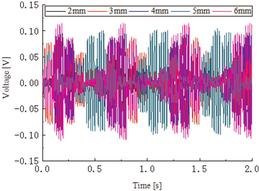
Figure 16 shows the self-induced voltage under different damper displacement inputs. The testing frequency was 1 Hz and the damper displacements were set as 2, 3, 4, 5, and 6 mm. The DC input for the excitation coil was set as 0.5 A, the AC voltage was 6.0 V, and the frequency was 1 kHz. As expected, the self-induced voltage increases with the increase in damper displacement.
Self-induced voltage under different damper displacement excitation inputs as the direct current input is set as 0.5 A.
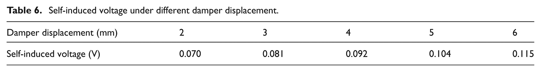
Table 6 and Figure 17 show the self-induced voltage under different damper displacement inputs. It can be seen that the self-induced voltage is proportional to the damper displacement, which demonstrates that the prototyped DSMRD has the ability of displacement integration. However, there is an offset when the displacement is 0. This is because the damper piston head deviates from the 0 position in the process of clamping.
Self-induced voltage under different damper displacement.
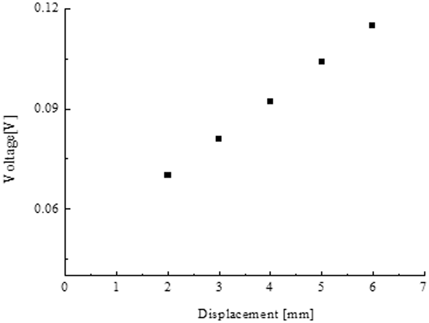
Self-induced voltage under different damper displacement inputs.
Self-induced voltages under continuously varying DC inputs
Figure 18 shows the self-induced voltages under continuously varying DC input for the excitation coil. The testing frequency is 1 Hz and the damper displacement is set from −5 to+5 mm. The AC voltage is 6.0 V and the frequency is 1 kHz. From Figure 18(a), it can be seen that the self-induced voltage maintains a certain value though the DC input for the excitation coil is changed from 0 to 1 A continuously. A further examination of the circled part is enlarged and shown in Figure 18(b), where the maximum value of the self-induced voltage is 0.075 V during the movement of the DSMRD. Thus, the self-induced coils will not be disturbed by the excitation coil of the MR damper.
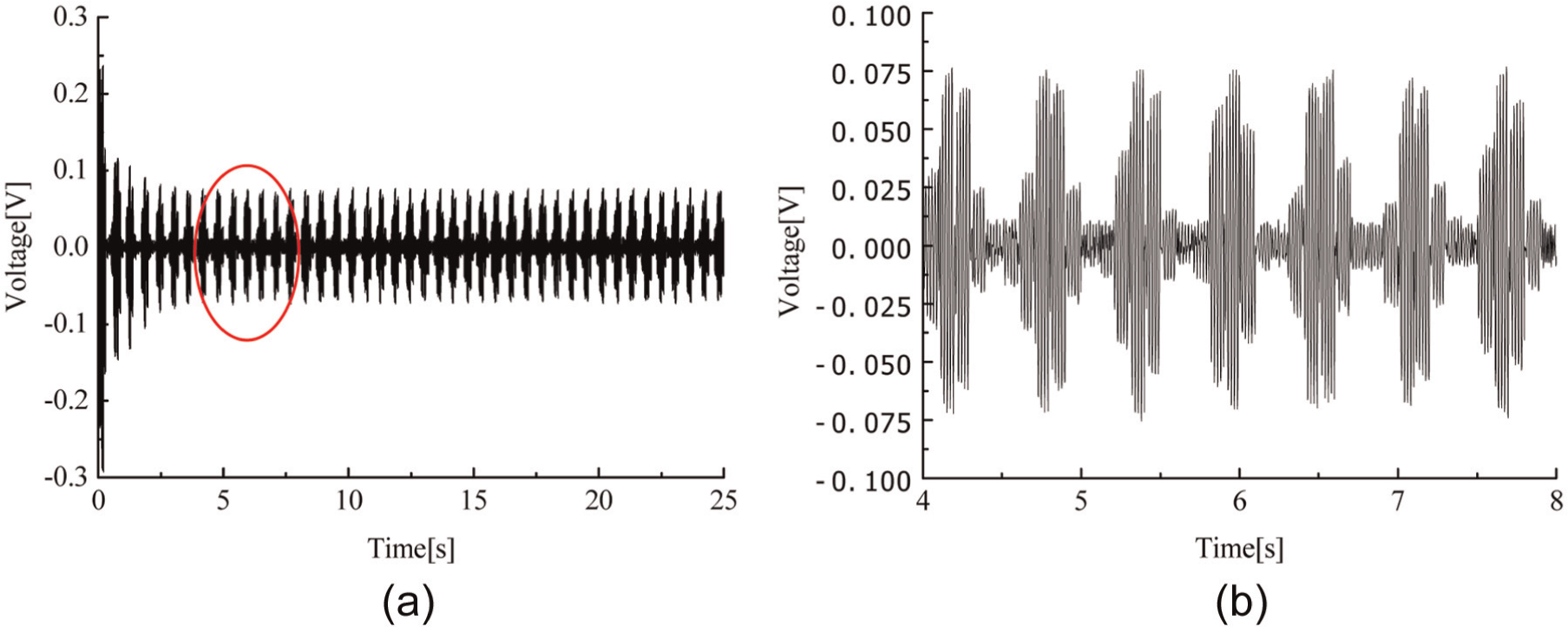
Self-induced voltage under continuously varying direct current inputs for the excitation coil: (a) the original waveform under the direct current input from 0 to 1 A continuously and (b) the enlarged waveform during the movement of the damper rod shown in the circle of (a).
Damping performance and MR effect
Figure 19 shows the damping forces of the damper at various magnetic fields with the coil currents ranging from 0 to 0.75 A. Similar to conventional MR dampers, this D-DSMRD shows an obvious MR effect with the peak damping force varying from 60 N at I = 0 A to about 170 N at I = 0.75 A. The effective damping coefficient of the D-DSMRD versus coil currents at the damper displacement lp = 5 mm is shown in Figure 20. Obviously, it shows an increasing trend with the magnetic field additions. When the current is 0 A, the effective damping coefficient is under 70 kN s/m; however, the coefficient could reach more than 150 kN s/m when the coil’s current is 0.75 A.
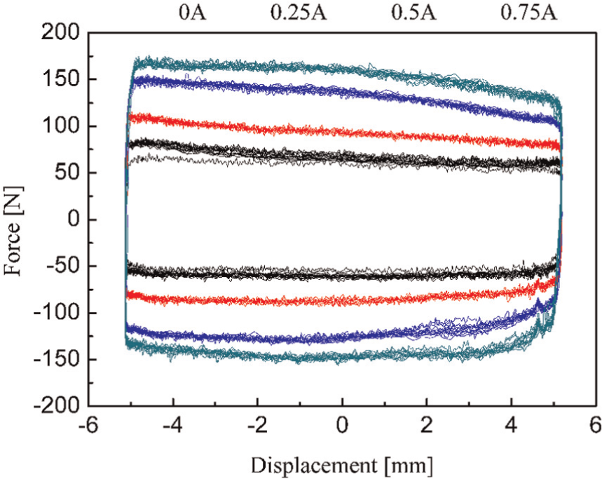
Diagram of experiment force–displacement.
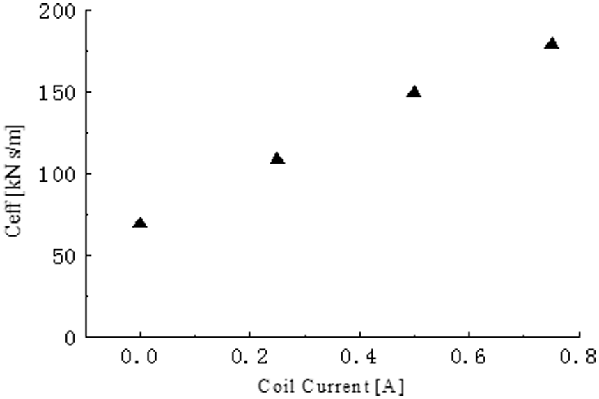
Equivalent coefficient of D-DSMRD versus coil currents, f = 0.2 Hz.
Conclusion
In this article, a D-DSMRD based on the ILVDS technology was developed. The major structure of the D-DSMRD is the excitation coil wound on the piston and two self-induced coils wounded on the winding cylinder. In the D-DSMRD, excitation coil was multiplexed by input DC which magnetizes MRF in the gap and 1 kHz frequency carrier of AC for the ILVDS.
The performance of the embedded sensor was evaluated through four selected experiments: (1) induced voltage at different positions, (2) induced voltage under different DC inputs for the excitation coil, (3) induced voltage under different displacements, and (4) induced voltage under continuously varying DC inputs. The results indicated that the induced voltage is proportional to the displacement but varies little with the DC inputs from the exciting coil. Additionally, the developed D-DSMRD has a performance similar to conventional MR damper. The damping coefficient of the damper increases steadily with the coil current input.
This research is expected to not only provide a new method to decrease the installation spaces and maintain spending of MR damper system but also lead to potential applications of MR damper in industries such as vehicles and bridges. Because of the proposed D-DSMRD structure, displacement sensors outside the MR damper are likely not to be needed.
Footnotes
Declaration of conflicting interests
The authors declared no potential conflicts of interest with respect to the research, authorship, and/or publication of this article.
Funding
This research was financially supported by the University of Wollongong UIC grant, the National Natural Science Foundation of China (No. 51165005), the Educational Commission and International Cooperation Project of Jiangxi Province of China (Nos GJJ13341, 20132BDH80001), and the Visiting Scholar Foundation of Key Laboratory of Fluid Power and Mechatronic Systems at the Zhejiang University (No. GZKF-201207).