
Abstract
Passive structural vibration reduction by means of shunted piezoelectric patches is addressed in this article. The concept of topology optimization, based on the solid isotropic material with penalization method, is employed in this work to optimize, in terms of damping efficiency, the geometry of piezoelectric patches, as well as their placement on the host elastic structure. The proposed optimization procedure consists of distributing the piezoelectric material in such a way as to maximize the modal electromechanical coupling factor of the mechanical vibration mode to which the shunt is tuned. An original finite element formulation, suitable to any elastic structures with surface-mounted piezoelectric patches, is proposed to solve the electromechanical problem. Numerical examples validate and demonstrate the potential of the proposed approach for the design of piezoelectric shunt devices.
Keywords
Introduction
Due to their capability of coupling mechanical stress and strain with an electric circuit, piezoelectric materials offer significant promise in a wide range of applications, such as energy harvesting, passive or semi-passive structural vibration damping, active vibration control, structural health monitoring, and micro/nano-electromechanical systems. In this article, the specific application of passive structural vibration and noise reduction by means of shunted piezoelectric patches is addressed. In this technology, an elastic structure is equipped with one or various piezoelectric patches that are connected to a passive electrical circuit, called shunt. The piezoelectric patches convert a fraction of the mechanical energy of the vibrating structure into electrical energy, which is then dissipated by Joule heating via the resistors of the shunt circuits. As compared to the active control techniques, those passive techniques have the advantage of being simple to implement, always stable, and do not require digital signal processors and bulky power amplifiers. Several shunt circuits are considered in the literature. The classical resistive (R) and resonant (RL) shunts have been initially proposed by Hagood and Von Flotow (1991). Then, improvements of those techniques have been studied by various authors using (1) several piezoelectric elements (Alessandroni et al., 2002; Casadei et al., 2010; Collet et al., 2009; dell’Isola et al., 2004; Hollkamp, 1994; Maurini et al., 2004; Trindade and Maio, 2008), (2) active fiber composites (Belloli et al., 2007; Seba et al., 2006), (3) adaptive shunts (Hollkamp and Starchville, 1994; Niederberger et al., 2004; Wu, 1998), and (4) semi-passive approach, commonly known as switch techniques (Badel et al., 2007; Cunefare et al., 2000; Ducarne et al., 2010; Richard et al., 2000). Since those techniques are passive, or semi-passive if some electronic components have to be powered, a critical issue is that their performances, in terms of damping efficiency, directly depend on the electromechanical coupling between the host structure and the piezoelectric elements, which has to be maximized. The optimization, in terms of damping efficiency, of the full electromechanical system composed by a host elastic structure with bonded piezoelectric patches connected to a shunt circuit is under study in this article. A modal model, based on an original finite element (FE) formulation (Thomas et al., 2009), adapted to any elastic structures with surface-mounted piezoelectric patches, is proposed to solve the electromechanical problem. Then, the so-called modal electromechanical coupling factors (MEMCFs) can be defined, each one being associated with one piezoelectric patch and one eigenmode of the structure. Those MEMCFs are found very close to the classical effective electromechanical coupling factor (EEMCF) defined in IEEE (1988). Several authors have pointed out their importance in the past (Caruso, 2001; Davis and Lesieutre, 1995; Lesieutre and Davis, 1997; Trindade and Benjeddou, 2009). The optimization relies on the fact that the tuning as well as the performances of the shunt connected to the piezoelectric patches depends only on two parameters: the MEMCF and the structural damping. Since the latter is in most practical cases a problem data, the only parameter that has to be considered is the MEMCF. This has been demonstrated in Thomas et al. (2009, 2012a, 2012b) for R and RL shunts, and in Ducarne et al. (2010) for switch techniques. The MEMCF being the main parameter, the optimization of the damping brought by the shunt can be divided into two successive steps. First, the MEMCFs must be maximized as a function of the patches’ geometries and location on the elastic structure. Then, the second step consists in determining the optimal electrical parameters of the shunt and estimating the damping efficiency. The optimal electric parameters are classically obtained as closed-formed expressions (Caruso, 2001; Ducarne et al., 2010; Thomas et al., 2012a) or can be numerically computed (Seba et al., 2006).
Optimizing the geometry and placement of piezoelectric patches on a host elastic structure has received large attention in the last decades. Recent reviews of the literature (Belloli and Ermanni, 2007; Frecker, 2003) show that active control applications are mainly considered. Only few studies address the application of piezoelectric shunts, and most of them keep fixed shape piezoelectric patches (e.g. rectangular) and only their size and/or positions are optimized (Belloli and Ermanni, 2007; Rosi et al., 2013; Sénéchal et al., 2010; Thomas et al., 2012b). This induces a constrained optimization problem that limits the optimality of the solution. The concept of topology optimization seems to be a good way to overcome this limitation and thus to find an optimal geometry for piezoelectric patches.
Topology optimization by distributing of isotropic materials has been proposed by Bendsøe and Kikuchi (1988) for the design of linear elastic structures. This method, which consists in finding the optimal distribution of material, has demonstrated its efficacy in a large number of applications. The basic form of a topology optimization problem can be defined as follows: distribute a given amount of material in a design domain such that an objective function is extremized (Sigmund and Torquato, 1999). An alternative to the classical homogenization approach is the solid isotropic material with penalization (SIMP) method based on the introduction of a penalization factor, which ensures that the continuous design variables are forced toward a black-and-white solution (i.e. with or without material). Even though the SIMP formulation is mesh dependent (number of elements of the discretized design domain), it became very popular because it is easy to implement in FE codes. Moreover, the efficacy of the SIMP method in a large number of structural problems is well recognized nowadays. For an overview of the homogenization approach and SIMP method to topology optimization and its mathematical background, the reader is referred to Bendsøe and Sigmund (2003) and references therein.
In the last decade, the SIMP method has successfully been employed for many applications with piezoelectric materials, especially in the active vibration control and energy harvesting domains (Carbonari et al., 2007; Kögl and Silva, 2005; Nakasone et al., 2008; Nakasone and Silva, 2011; Rupp et al., 2009; Silva, 2009; Silva and Kikuchi, 1999; Wein et al., 2009; Zheng et al., 2009). In the context of shunt damping applications, the vibration suppression of a hard disk driver actuator arm using piezoelectric shunt damping with a topologically optimized piezoelectric transducer was investigated by Sun et al. (2009). In this work, the authors use the topological optimization module in the ANSYS FE commercial code to optimize the shape of the piezoelectric material coupled in the arm. To the best knowledge of the authors, this article is the only contribution that applies a topology optimization method to piezoelectric shunt problems. Therefore, from the above analysis of the open literature, it is clear that insufficient attention has been given to the topology optimization technique in the context of piezoelectric shunt damping. Exploiting this fact, the concept of topology optimization, based on the SIMP method, is employed in this work to find an optimal distribution of the piezoelectric material over a host elastic structure to improve damping efficiency for a resonant shunted system. The cases of resistive shunt and switch techniques are not covered here, but the proposed method remains valid. An optimization algorithm, based on the work of Silva and Kikuchi (1999), is developed with the MEMCF as objective function. Moreover, the occurrence of effect of self-penalization of piezoelectric materials in topology optimization (see, for example, Wein et al., 2011) for shunted piezoelectric problems is analyzed, which is original.
The outline of the article is now described. In section “Electromechanical model,” an electromechanical FE model suitable for any elastic structures with surface-mounted piezoelectric patches and the MEMCFs are briefly recalled. In section “Topology optimization: SIMP method,” the concept of topology optimization applied to piezoelectric materials and the formulation of the optimization problem are presented. In section “Numerical implementation,” the numerical implementation is discussed with emphasis on the optimization algorithm. Finally, section “Examples” proposes numerical examples to validate and analyze the optimization strategy.
Electromechanical model
In this section, an original electromechanical FE formulation (Thomas et al., 2009), adapted to any elastic structures with surface-mounted piezoelectric patches, is briefly recalled. Then, a reduced-order model of the problem based on a normal mode expansion is introduced.
FE formulation
We consider the vibration of an arbitrary elastic structure with
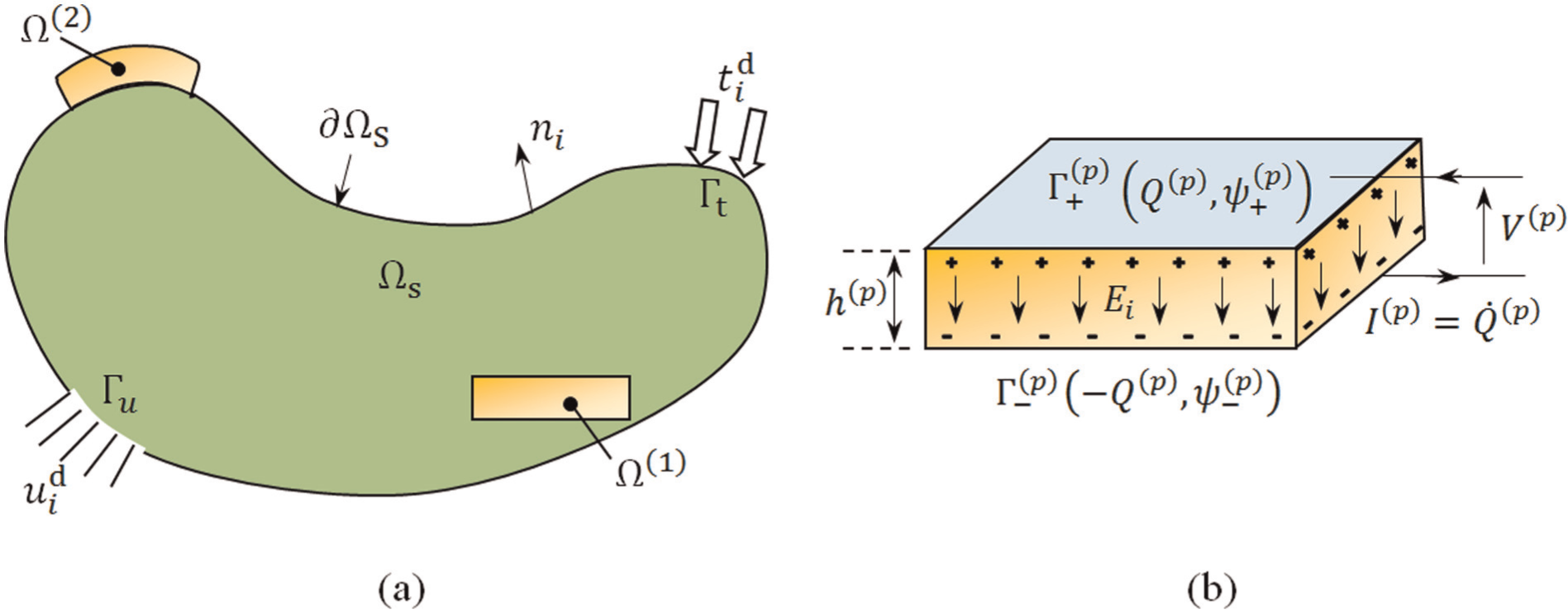
(a) An elastic structure with two piezoelectric patches and (b) the pth piezoelectric patch submitted to an uniform electric field vector
Using a set of practical assumptions, detailed in Thomas et al. (2009), we can obtain an original variational formulation and then an efficient FE formulation of the above electromechanical spectral problem, which is given by
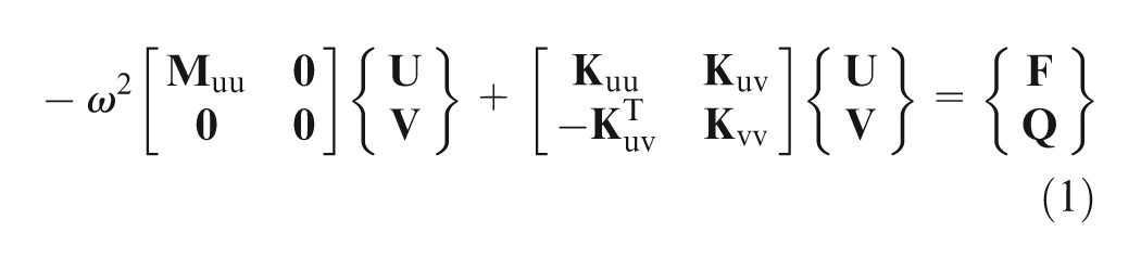
where
The above discretized formulation equation is adapted to any elastic structures with surface-mounted piezoelectric patches. Its originality lies in the fact that the system electrical state is fully described by very few global discrete unknowns: only a couple of variables per piezoelectric patch, namely (1) the electric charge contained in the electrodes and (2) the voltage between the electrodes. Once the electrical part of the problem is fully discretized at the weak formulation step, by introducing the above cited voltage/charge variables, without any restriction on the mechanical part of the problem, any standard FE formulation can be easily modified to include the piezoelectric patches and thus the effect of an external electrical action. A second advantage of this formulation is that since global electrical variables are used, realistic electrical boundary conditions are naturally introduced. First, the equipotentiality in any of the patches’ electrodes is exactly satisfied when introducing the potential difference variable. Second, the use of the global charge contained in the electrodes, as the second electrical variable, is realistic since plugging an external electrical circuit to the electrodes of the patches imposes only the global charge contained in the electrodes and not a local charge surface density. Another advantage of using the global charge/voltage variables is that they are intrinsically adapted to include any external electrical circuit into the electromechanical problem and to simulate the effect of shunt damping techniques. In this case, neither
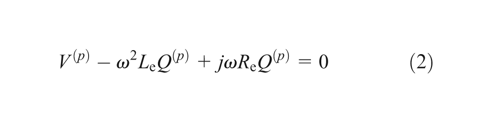
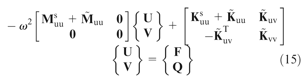
Combining equations (1) and (2) and considering a mechanical viscous damping in the system, we finally obtain the general FE formulation of the electromechanical spectral problem when the piezoelectric patches are shunted

where
Depending on whether the patches are short-circuited (
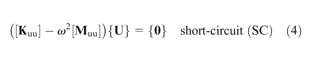
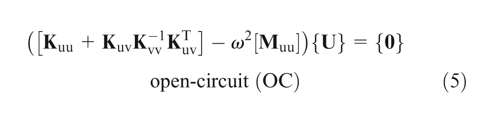
where the added stiffness term
Reduced-order model and coupling factors
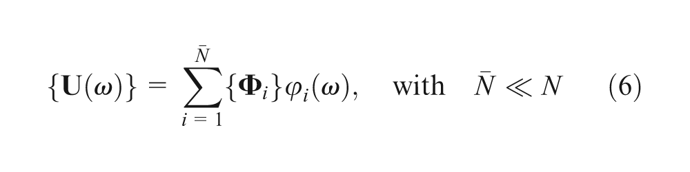
In this section, a reduced-order formulation of the discretized problem of equation (3) is introduced. The mechanical displacement unknown vector is projected onto a truncated modal basis containing the first short-circuit eigenmodes. The main motivation of choosing this particular basis is that it can be computed with a classical elastic mechanical formulation, whereas open-circuit modes depend also on the piezoelectric system properties. This basis could be enriched by other functions (e.g. static modes), which is out of the scope of this article. Moreover, this section also introduces the modal coupling factors and recalls the optimal values for the electrical parameters of resonant shunts.
The shunted electromechanical problem given by equation (3) can then be reduced by projecting the mechanical displacement into the first
As a result, the reduced problem consists in solving the following system
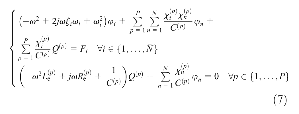
where
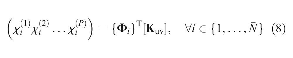
These modal coupling coefficients
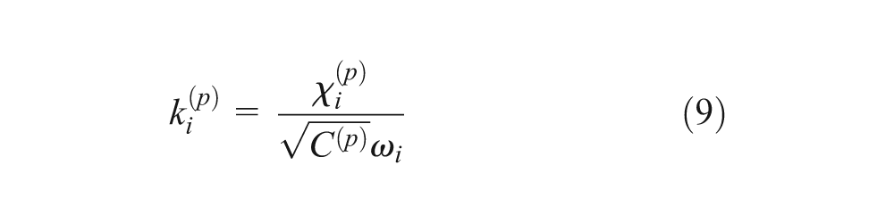
Under the assumption that the modal truncation to one mode is valid around the ith mode, it can be shown that the MEMCF
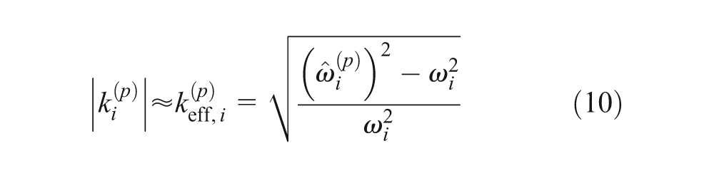
where
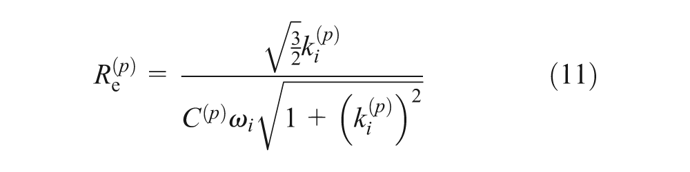
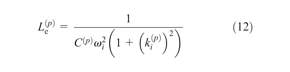
Moreover, the optimal values for the electrical parameters of a resonant shunt, determined in Thomas et al. (2012a), are recalled in equations (11) and (12). These results depend only on (1) the natural frequency in short circuit of the considered vibration mode as well as its modal coupling factor and (2) the equivalent electrical blocked capacity of the patches
For simplicity, the formulation presented in this section considers one shunt circuit for each piezoelectric patch. For the case of several piezoelectric patches connected, in series or parallel, to one shunt circuit, additional considerations need to be included in the model. For details, we refer the reader to Thomas et al. (2009).
Topology optimization: SIMP method
Piezoelectric material model
Topology optimization based on the SIMP method is a powerful structural optimization technique that has proved to be very efficient for many applications. It combines the FE method with an optimization algorithm to find the optimal material distribution inside a given domain. The book by Bendsøe and Sigmund (2003) brings a comprehensive and unified description of this topology optimization method.
The application of the SIMP method to piezoelectric materials has been done first by Silva and Kikuchi (1999) to design piezoelectric transducers. Then, many studies involving the use of piezoelectric materials have applied the topology optimization based on the SIMP method with success, especially in the active vibration control and energy harvesting domains (Kögl and Silva, 2005; Nakasone and Silva, 2011; Rupp et al., 2009; Zheng et al., 2009).
The idea is to introduce the so-called pseudo-density
Using the standard SIMP interpolation form
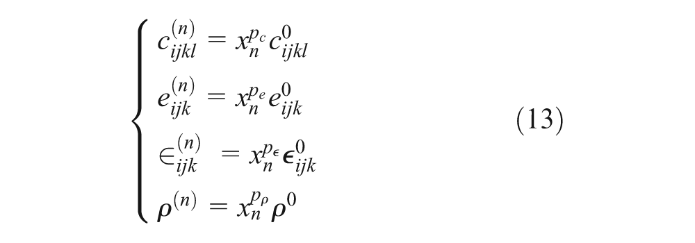
where
For the choice of penalty exponents, it is common practice to use for the density
Considering the new material properties of equations (13), the local FE stiffness and mass matrices of the piezoelectric patches become
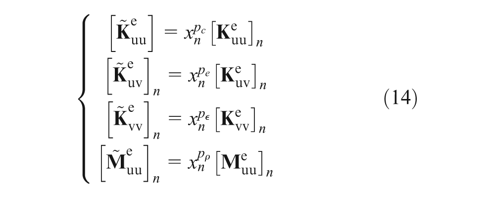
The FE formulation of equation (1) is now written as
where
Note that other penalization approaches can be found in the literature:
In Kögl and Silva (2005), the authors have proposed a new piezoelectric material model called piezoelectric material with penalization and polarization (PEMAP-P) that considers, in addition to the pseudo-density
The standard SIMP interpolation form
Optimization problem
To improve the damping level for passive or semi-passive shunted piezoelectric devices, a key issue is the optimization of the whole system, in terms of location and geometry of the piezoelectric patches and electric circuit components’ choice. It was shown in Thomas et al. (2009) that these two optimizations, mechanical and electrical, can be realized separately. Moreover, it is proved in Hagood and Von Flotow (1991), Davis and Lesieutre (1995), Becker et al. (2006), and Thomas et al. (2012a, 2012b) that the only parameters to maximize are the modal coupling factors (MEMCF), which characterize the energy exchanges between the mechanical structure and the piezoelectric patches for a given mode. Since the optimal values of the electric circuit parameters are known as functions of the MEMCF and the system structural characteristics, they can be evaluated in a second step. Thus, the mechanical optimization consists in maximizing the MEMCF by optimizing the patches’ positions and geometries, that is, finding the best design.
Considering all these features, the optimization problem can be described as
Maximize:
where
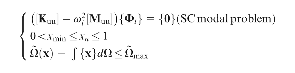
where
It is important to note that the objective function is defined here only as a function of one eigenvalue contrary to the work of Silva and Kikuchi (1999). In that work, the authors propose multiobjective functions written in terms of many eigenvalues to overcome the problem of switching the vibration modes during the optimization. In this work, in order to surmount this eventual problem, the modal assurance criterion (MAC) is used in order to identify a particular mode. Therefore, even though the modes switch during the optimization procedure, the MEMCF relative to the selected mode to be attenuated is maximized. Moreover, in the cases that natural frequencies are widely spaced and/or piezoelectric patches do not significantly change the dynamics behavior of the host structure, this switching problem can be neglected.
Sensitivity analysis
As shown in Kögl and Silva (2005), this work uses sequential linear programming (SLP) to solve the optimization problem. This requires knowledge of the sensitivities (gradients) of the objective function
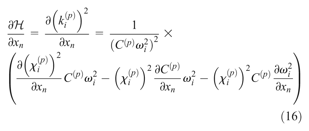
where
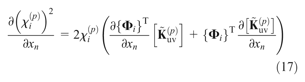
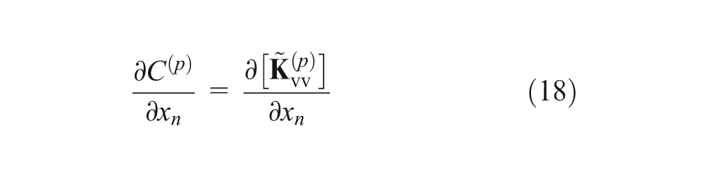

Equations (17) to (19) correspond to the sensitivities of the coupling coefficient
Due to the piezoelectric material model proposed in equation (13), the matrices
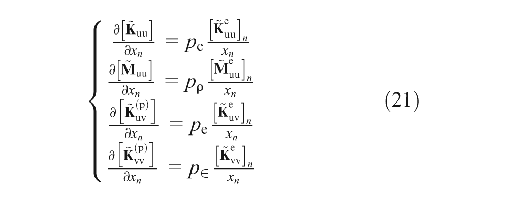
The sensitivities of the objective function
Numerical implementation
The numerical implementation proposed in this study is shown in Figure 2. Figure 2(a) presents the main algorithm for solving the piezoelectric shunted problem and Figure 2(b) details the optimization algorithm to optimize the placement and geometry of piezoelectric patches. In order to construct the electromechanical FE models and solve the problems, the FE code Nastran® is used in association with MATLAB software (Pereira da Silva et al., 2012). Nastran is exploited here to create the elastic part of the model and to solve the eigenvalue problem. MATLAB is used to manage Nastran, to construct the electric part of the models (piezoelectric and dielectric matrices), to solve the optimization procedure, and to compute the frequency responses. Throughout the procedure, much information is exchanged between MATLAB and Nastran. For this reason, the Awk programming language is used to allow a very fast reading and writing for data extraction and reporting.
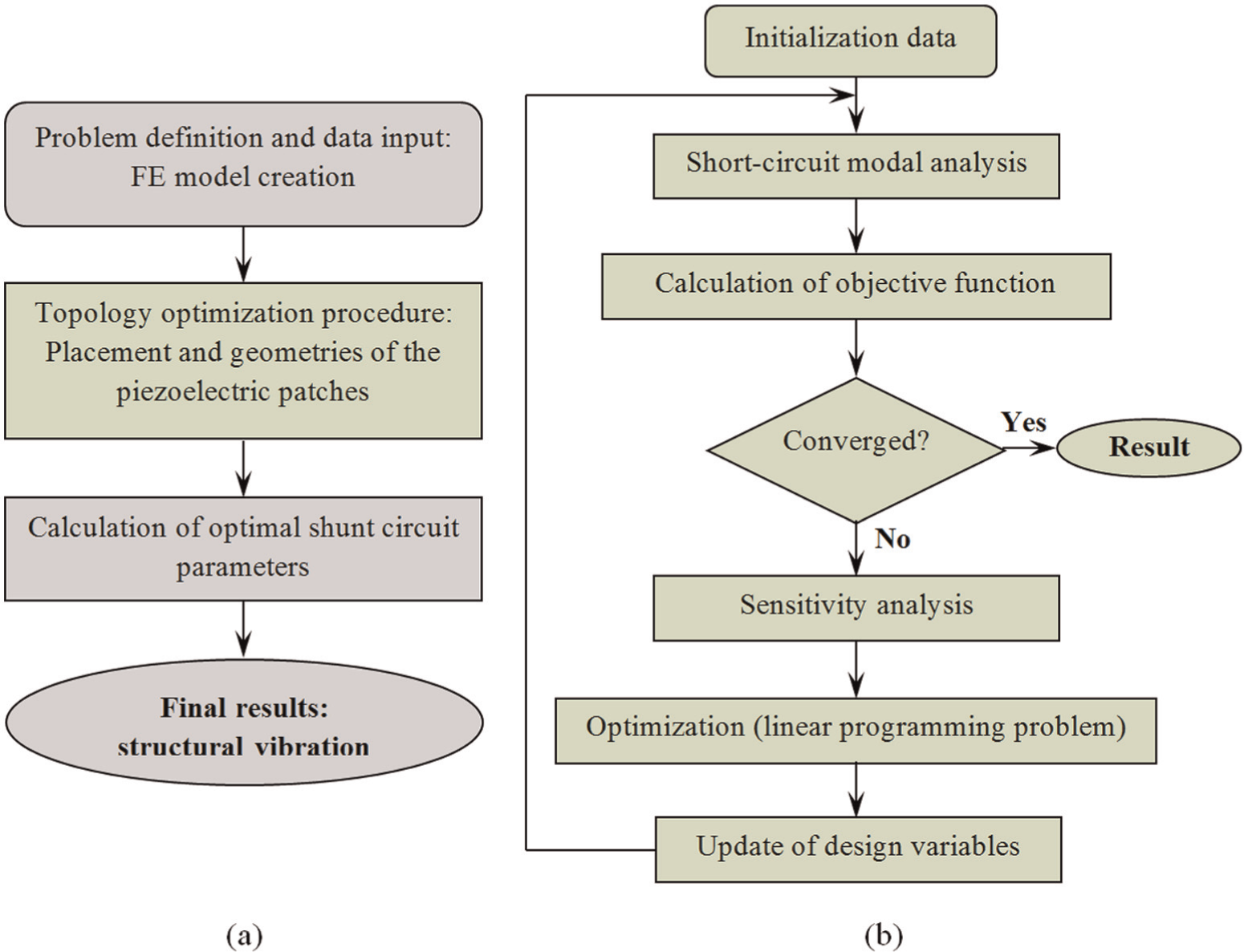
Implementation of the proposed topology optimization approach: (a) main algorithm and (b) optimization algorithm.
Main algorithm
In a first step, the problem is defined and the FE model is created. In this step, the vibration modes to be controlled and the potential positioning areas of the piezoelectric patches are specified. We consider here for sake of simplicity, only one piezoelectric device for each mode to be controlled. In a second step, an optimization algorithm, detailed in the next section, is applied in order to find the best design of piezoelectric patches (position and geometry). Then, the optimal electric parameters (resistance and inductance values) of shunt circuits are determined using equations (11) and (12). Finally, the reduced-order model (equations (7)) is used to solve the frequency response of the system and to determine the shunt damping attenuation.
Optimization algorithm
The material assumptions and FE model of section “Piezoelectric material model” are employed to solve the SC modal analysis and calculate the objective function. The design variables are the values of the pseudo-densities
This work uses SLP to solve the optimization problem. This method has been successfully applied to topology optimization in Sigmund and Torquato (1999), Silva and Kikuchi (1999), Kögl and Silva (2005), and Nakasone and Silva (2011). It consists of sequential solution of approximate linear subproblems that can be defined by writing a Taylor series expansion for the objective function around the current design point
As a result, an optimum distribution of
To assess the quality of the final design, the amount of intermediate material (“grayness”) can be quantified by introducing the so-called measure of non-discreteness (Sigmund, 2007)
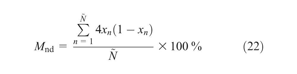
A fully discrete design (no elements with intermediate density values) is represented by
Examples
In the following, the proposed topology optimization approach is applied to find the better placement and geometry of piezoelectric patches for various vibration problems.
Cantilever beam with one piezoelectric patch
In this first example, we propose to validate our optimization procedure by comparison to an analytical solution given in Thomas et al. (2012b). The objective is to find the optimal position and geometry of a piezoelectric patch mounted on a cantilever beam in order to maximize the MEMCF for a given bending vibration mode.
The system under study consists of a cantilever beam with one piezoelectric device, as sketched in Figure 3. The beam is made of aluminum (E = 74 GPa, v = 0.33, and ρ = 2700 kg/m3) with
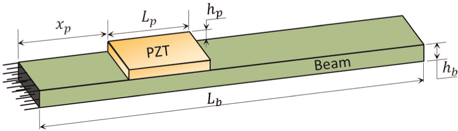
Cantilever beam with one piezoelectric patch.
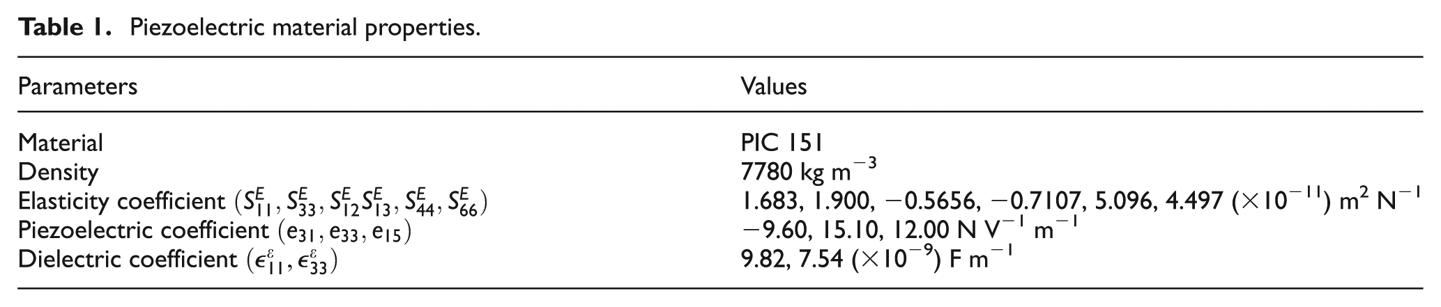
Piezoelectric material properties.
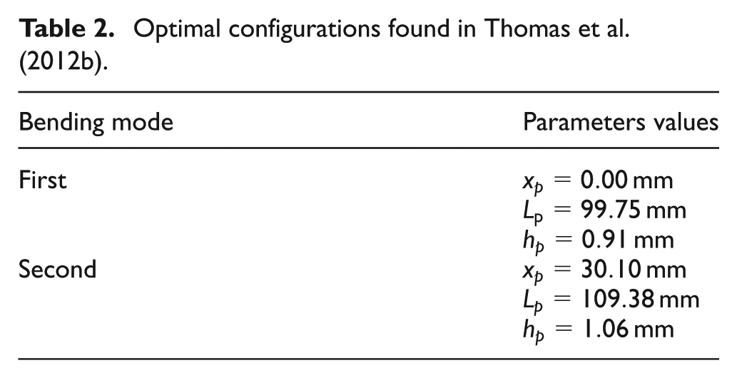
For this system, Thomas et al. (2012b) proposed an analytical solution for the optimization of the position
Optimal configurations found in Thomas et al. (2012b).
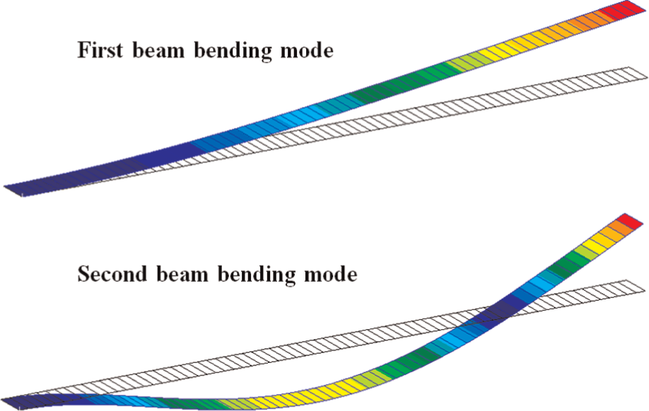
Deformed shapes of the first two beam bending modes.
Our optimization approach is based on the FE modeling of the system. Thus, the beam and piezoelectric layer are modeled with 70 linear quadrilateral shell elements (QUAD 4), according to the first-order shear deformation laminate theory (Reddy, 2004). In order to ensure the comparison with the analytical solutions, the system is discretized with only one element through the width, as shown in Figure 4. With this modeling and for a fixed thickness of the piezoelectric layer, the optimization problem consists in finding the optimal length of a rectangular patch
As previously explained, the performance of our optimization approach depends on the choice of the penalty exponents
Figure 5 shows the results of the proposed optimization methodology in terms of the penalty exponents and the measure of non-discreteness of the first two bending modes. Figure 6 gives the evolution of the MEMCF through the optimization procedure (first 40 interactions). It is important to note that Figures 5 and 6 present only the results for six combinations of penalty exponents. The case of
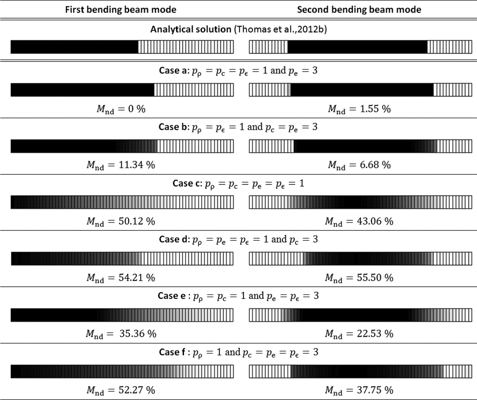
Resulting topologies of density
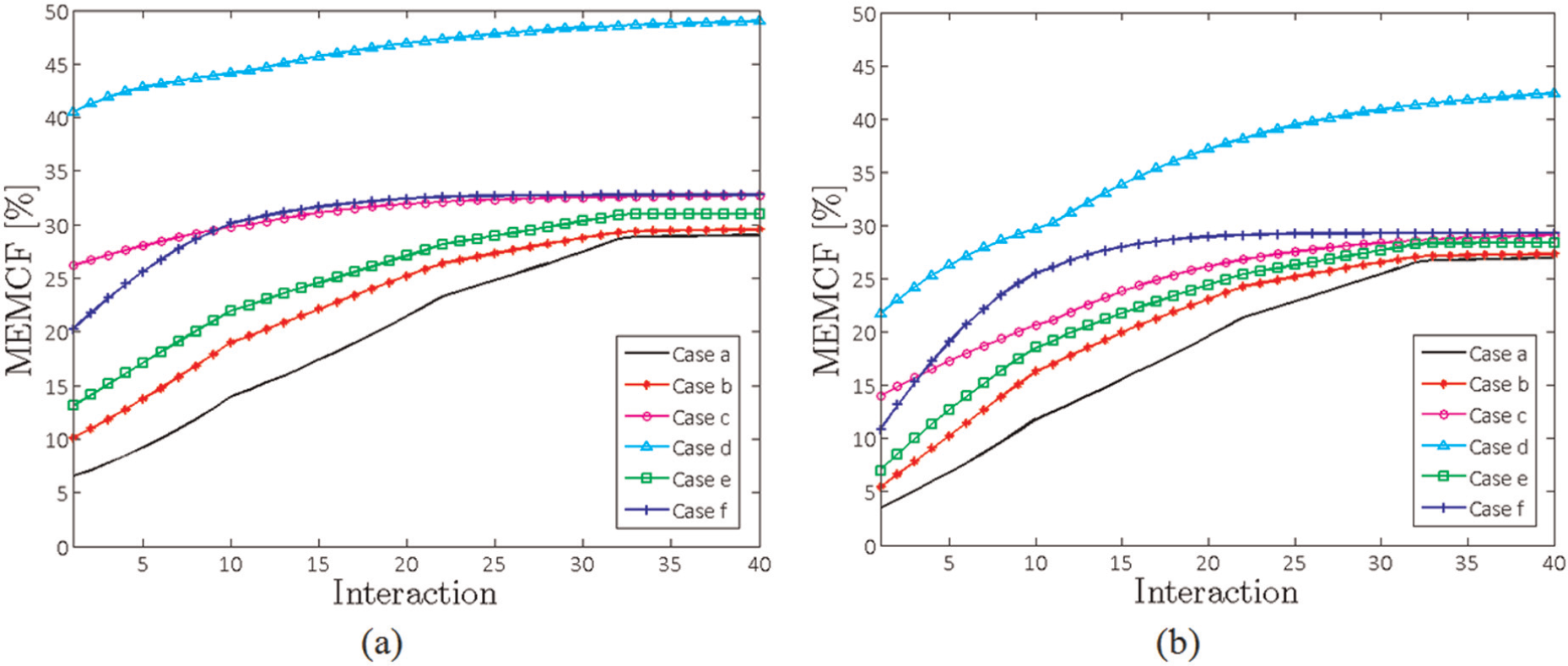
Evolution of the MEMCF through the optimization procedure. Case a:
As expected, the combination of penalty exponents
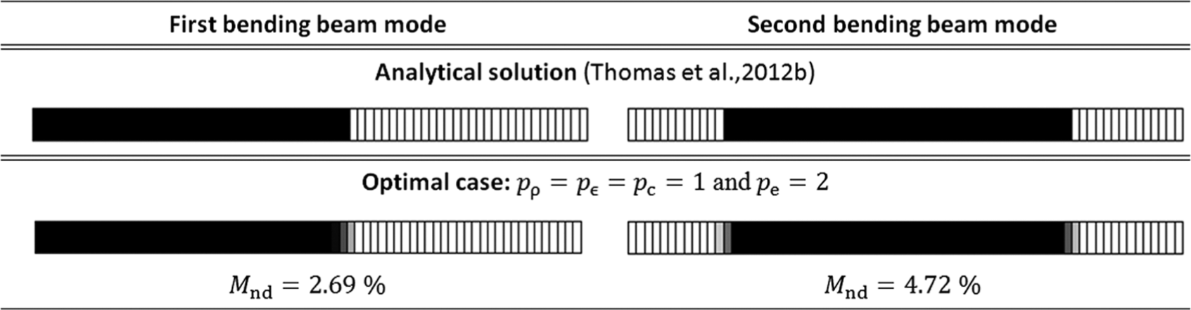
Resulting topologies for the first and second beam bending modes with
This first example validates our optimization approach and shows its efficiency compared to analytical solution. The combinations of penalty exponents that penalize only the electromechanical coupling matrix
Single-mode RL shunt control of a baffle-less automotive muffler
In this example, the vibration reduction problem of a muffler-like structure using a piezoelectric RL shunt device is considered (Raju et al., 2005). The muffler is made of aluminum (
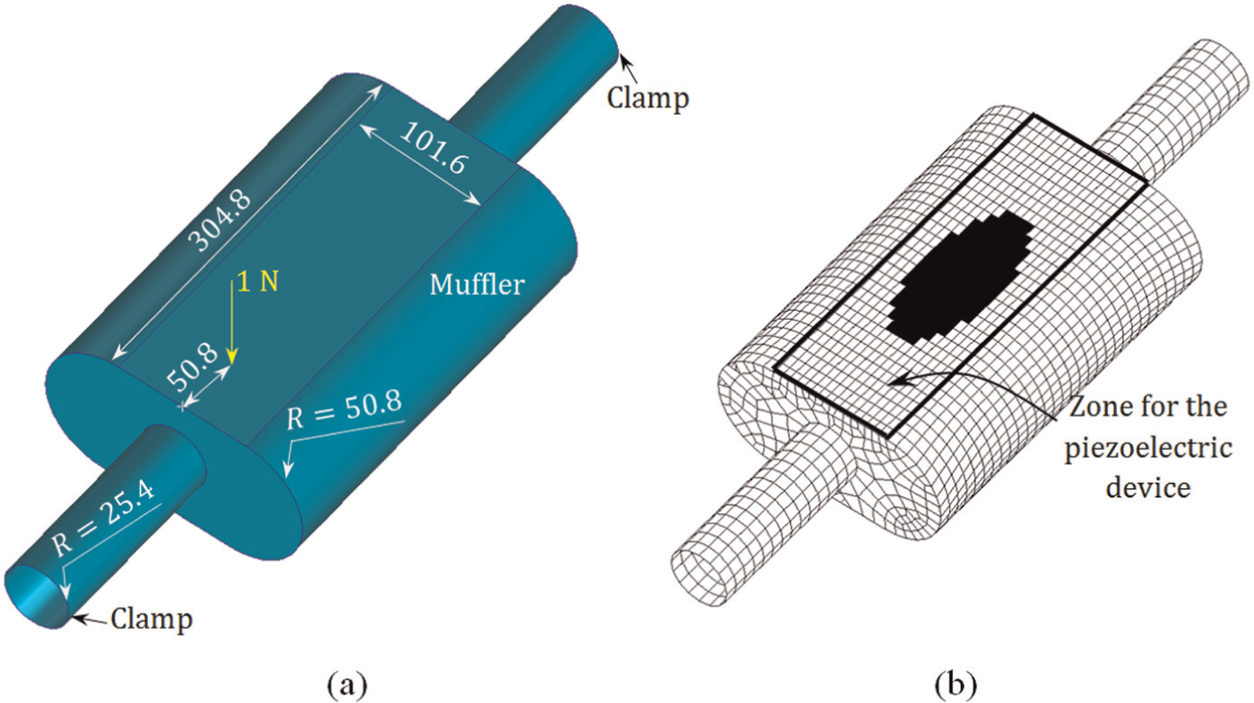
Muffler-like structure with the inlet and exhaust pipes: (a) geometric configuration and boundary conditions (all dimensions are in mm) and (b) finite element mesh and optimal configuration for the piezoelectric shunt system.
A piezoelectric device is perfectly bonded on the top surface of the muffler and connected to a RL shunt circuit in order to reduce the vibration of the second mode of the structure. The material properties of the piezoelectric device are given in Table 1 and its thickness is 0.635 mm.
The proposed topology optimization procedure is applied to distribute the piezoelectric material on the top muffler surface in order to maximize the MEMCF for the second vibration mode. A resonant RL shunt is then tuned in order to achieve maximum energy dissipation of this mode (Figure 9). The optimal values of the resistor and inductor, calculated through the formulas given by equations (11) and (12), are
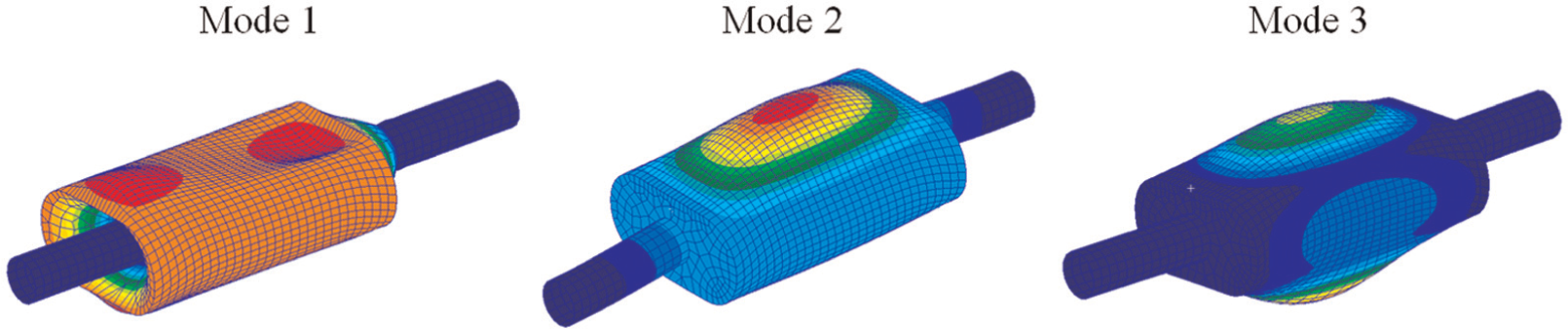
First three muffler vibration modes.
Concerning the optimization procedure, an upper bound
Figure 8(b) shows the best design obtained with the proposed optimization procedure. In Figure 10, the FRFs in the excitation point are plotted and compared for (1) muffler without patch, (2) short-circuited case, and (3) shunted case. This figure shows that the resonant magnitude of the second mode has been significantly reduced. In fact, the strain energy contained in the piezoelectric material is converted into electrical energy and hence dissipated into heat using the RL shunt device. In this example, the optimization method provides excellent damping for the select mode. This can be verified by comparing to other geometries and positions of the patch presented in Pereira da Silva et al. (2013).
Frequency response functions of the muffler. Attenuation of vibration mode 2.
Multi-mode RL shunts control of sound power radiated from a thin plate
In the last example, a free-clamped rectangular plate with two rectangular reinforcements perfectly bonded on its underside surface is considered. The plate and the reinforcements are made of 2-mm-thick aluminum plates (
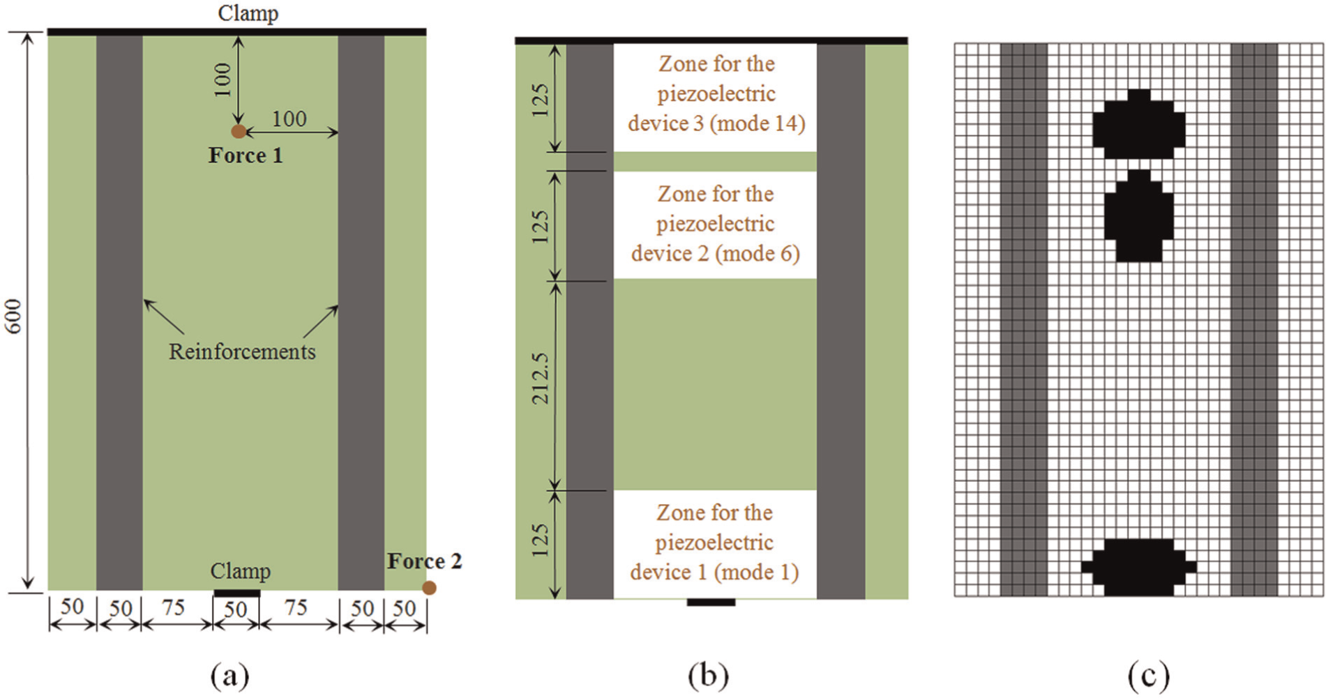
Free-clamped rectangular plate with reinforcements (all dimensions are in mm): (a) geometric configuration and boundary conditions, (b) delimited zones for the piezoelectric devices, and (c) optimal configuration for the piezoelectric shunt system.
In the low-frequency range (0–430 Hz), the most radiating modes are modes 1, 6, and 14 (Figure 12). The computation of these modes was done with the elemental radiator method presented in Pereira da Silva et al. (2012). In order to reduce the sound radiation of these modes and get a multi-modal damping of the structure, a shunt system with three piezoelectric devices is used. They are considered made of PIC 151 (see Table 1 for the properties) with 0.5 mm of thickness. Note that other techniques using piezoelectric systems can be applied for control of sound radiated and transmitted by thin structures (see, for example, Rosi et al., 2010).
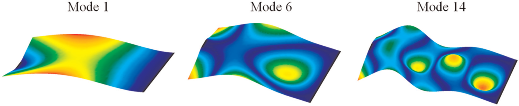
Deformed shapes of the modes to be controlled.
As in the previous example, the proposed optimization procedure described in Figure 2(a) and (b) is applied in order to maximize the MEMCF, which provides the most damping for the select modes. Note that three zones on the top surface of the plate were delimited to attach and design each piezoelectric device (they are assumed perfectly bounded), as shown in Figure 11(b). In addition, an upper bound
Concerning the FE discretization, we have used for the plate 1536 linear quadrilateral shell elements (QUAD 4) based on the first-order shear deformation theory. The portions of the plate covered with piezoelectric material and the piezoelectric layers themselves have been modeled according to the first-order shear deformation laminate theory (Reddy, 2004).
The FRFs are computed with a modal reduction approach using the first 40 eigenmodes of the structure with the piezoelectric patches in SC configuration. Mechanical damping was introduced through a modal damping coefficient
Figure 11(c) shows the best design obtained with the optimization procedure and Table 3 gives the resulting MEMCFs together with the optimal values of the shunts’ electrical parameters.
MEMCF and optimal values for the electrical parameters of the shunt circuits.
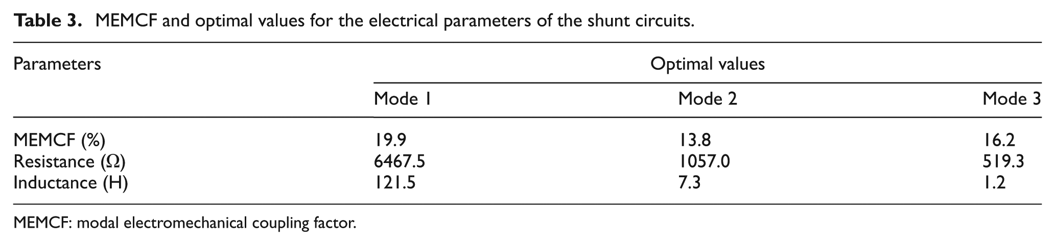
MEMCF: modal electromechanical coupling factor.
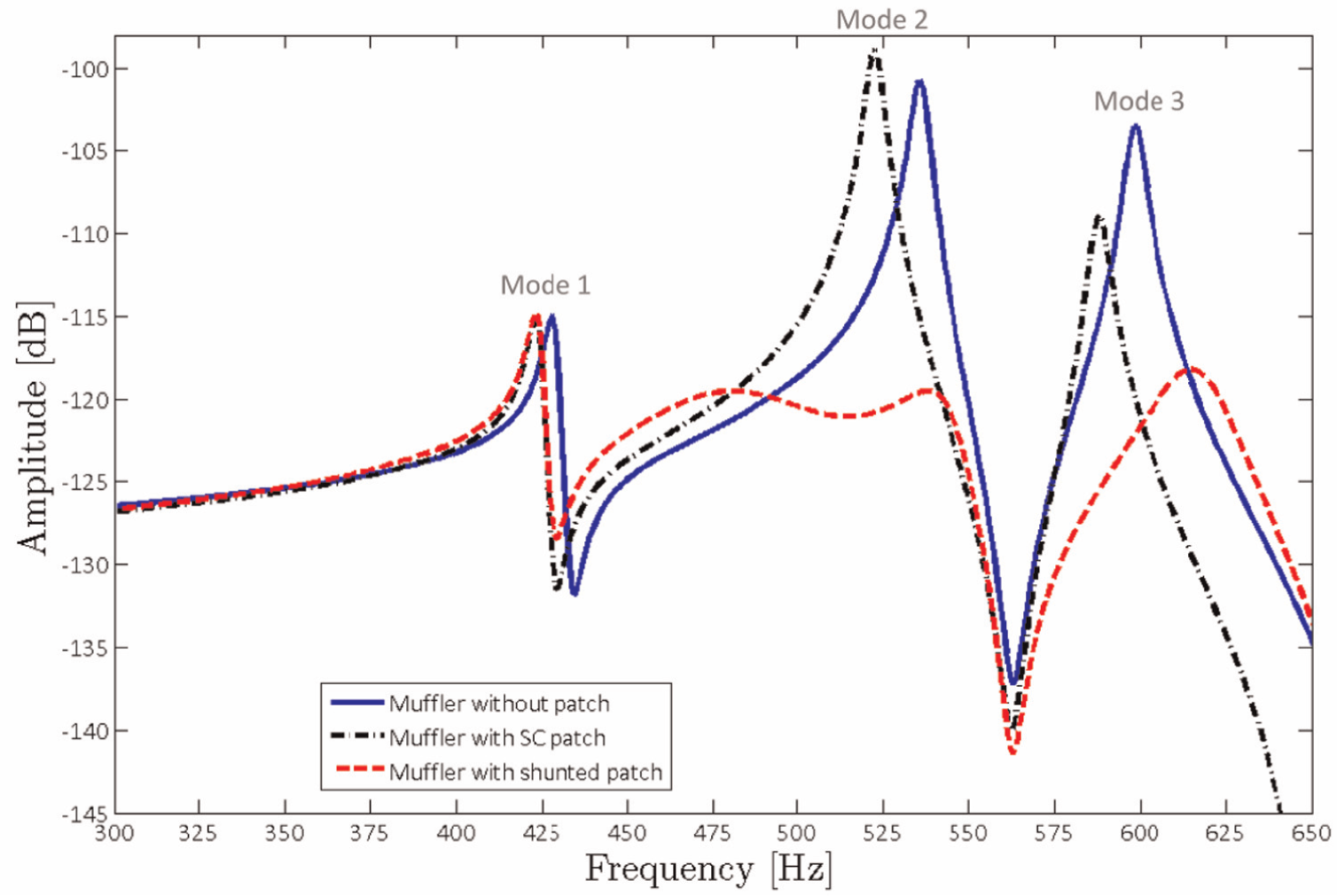
Figure 13 presents the FRFs of the system with and without shunt control at the same point where the harmonic force 1 is applied. This figure illustrates again the performance of the shunt technique in vibration and sound radiation reduction of the select modes. These results also show that the optimization of the patches geometry causes better performance in terms of attenuation compared to arbitrary geometries and demonstrates the effectiveness of the proposed approach.
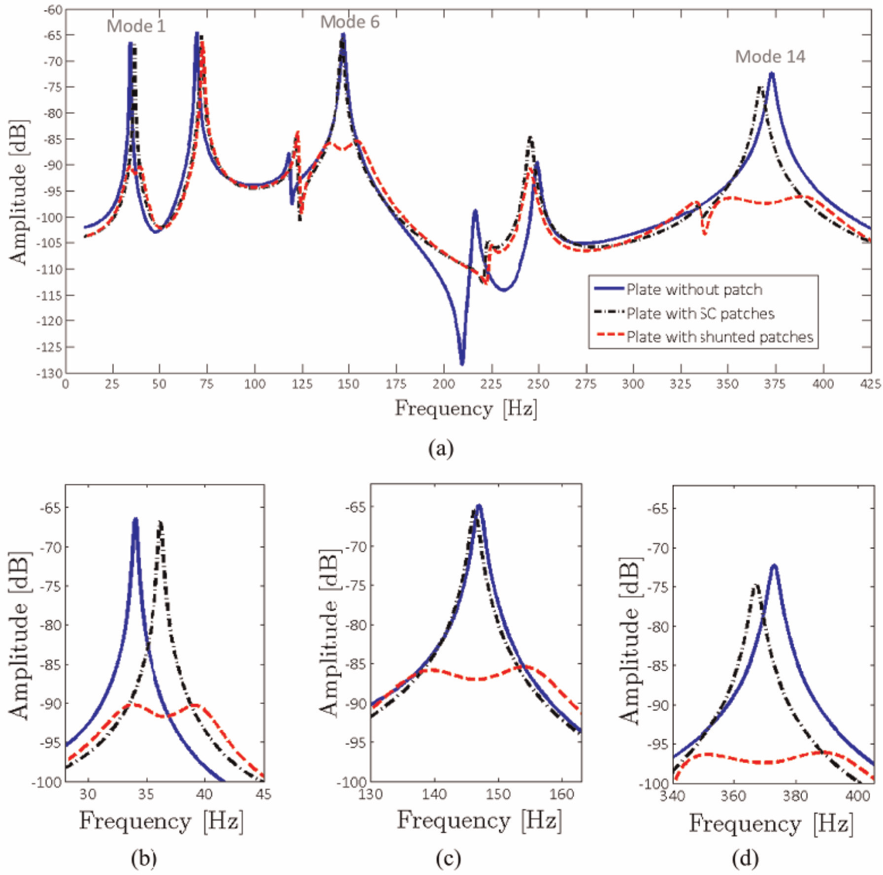
Frequency response functions of the plate: (a) frequency range (0–430) Hz, (b) attenuation of mode 1, (c) attenuation of mode 6, and (d) attenuation of mode 14.
It is important to note that piezoelectric patches with unconventional shapes have been obtained from the optimization procedure in the above examples. From the viewpoint of the manufacture, piezoceramics are normally produced by sintering that allows large variety of shapes and sizes. However, a constant thickness between the electrodes is preferable in order to maximize the electric field at any point during the polarization and thus obtain a high piezoelectric coupling. The lead zirconate titanate (PZT) elements are therefore usually straight plates.
Conclusion
The present contribution is dedicated to the study of passive vibration damping using piezoelectric patches and resonant shunt circuits. The concept of topology optimization is successfully applied in order to optimize the placement and geometry of piezoelectric patches. An optimization algorithm is employed and validated. A set of penalty exponents is proposed that yield excellent results with a very small grayness and so little post-processing. Numerical examples demonstrate the effectiveness of the proposed approach for the design of piezoelectric devices in shunt damping problems.
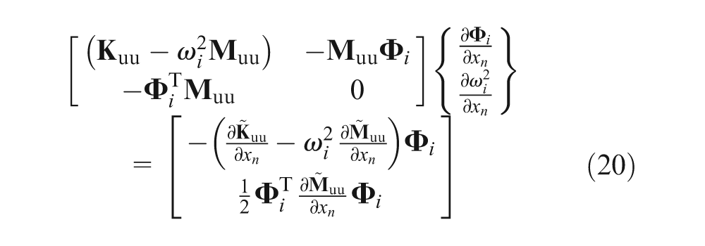
The evaluation of the sensitivity of the short-circuit eigenvector
Footnotes
Declaration of conflicting interests
The authors declared no potential conflicts of interest with respect to the research, authorship, and/or publication of this article.
Funding
The authors received no financial support for the research, authorship, and/or publication of this article.