
Abstract
This article focuses on the design, fabrication, testing, modeling, and validation of a spanwise variable camber section of a helicopter rotor blade. The lower surface skin was slit aft of the trailing edge spar and subjected to a spanwise warping actuation input. A kinematic linkage facilitates a corresponding chordwise motion of the skin along the span length (from zero at the no-camber end to maximum at the maximum camber end). Input warping actuation of 0.18 in length produced an 18° camber variation over a 45 in span section of a modified CH-46 blade. Finite element model predictions of the active camber section showed good agreement with benchtop test data for both the output camber for a given warping actuation input and the corresponding actuation force required. Finite element results suggest that some geometry distortions in the active camber section could be experienced due to the presence of centrifugal and aerodynamic loads, but these distortions could be alleviated with the introduction of a shear-flexible (but stiff through the thickness) core.
Introduction
On modern rotors, much effort is devoted to optimization of airfoil sections, blade planform, twist distribution and tip shape, to maximize rotor performance over the operating regime. However, since the optimal design varies with operating condition, a fixed-geometry rotor generally constitutes a compromised solution. Through reconfiguration, or active control, during operation performance, improvement may be realized over diverse operating conditions. Several researchers (Hall et al., 1994; Kroninger, 2008; Moffitt and Bissell, 1982; Rand et al., 2004; Wachspress et al., 2005) have examined the optimal airload distribution over the rotor disk that would produce the required rotor forces and moments for trim at the lowest power requirement. But how these optimal airload distributions can be practically achieved remains a question.
A different approach adopted by another set of researchers uses practically implementable rotor active control methods for performance improvement. Although the theoretically optimal airload distributions are not realized, using rotor higher harmonic control (McHugh and Shaw, 1978; Miao et al., 1986; Nguyen and Chopra, 1990, 1992; Robinson and Friedmann, 1991; Shaw and Albion, 1980; Shaw et al., 1989; Walsh, 1986; Yen, 1981), or individual blade control (IBC; Arnold, 2003; Cheng and Celi, 2005; Cheng et al., 2003; Jacklin et al., 1994, 1995; Kessler et al., 2003; Liu et al., 2008) through root pitch actuation, active rotor twist, or trailing edge flaps, these researchers have examined the power reductions practically possible. However, the improvements are generally shown to be very modest (not greater than 1%–2%), except near the envelope boundaries (very high gross weight or airspeed, where reductions of the order of 4%–6% are predicted). A review of various approaches considered for helicopter active control is available in Chopra (2002) and Giurgiutiu (2000).
One of the factors to consider is that while the rotor active control approaches referenced in the previous paragraph allow manipulation and modulation of the rotor airloads around the azimuth, they are unable to simultaneously introduce independent control along the span. Thus, it is difficult to realize theoretically optimal airload distributions around the rotor disk. One approach to overcome this limitation is through the use of spanwise-segmented control effectors (spanwise-segmented active Gurney flaps or trailing edge flaps) that could allow the simultaneous spanwise and azimuthal tailoring of the airloads for torsionally stiffer rotors (Bae and Gandhi, 2010; Bae et al., 2009; Leon and Gandhi, 2009).
Another approach is quasi-static rotor reconfiguration for performance improvement. Unlike rotor higher harmonic control (HHC) or IBC, where moderate- to low-amplitude actuation inputs are introduced at harmonics of the rotor speed, larger geometry changes are sought, not per rotor revolution, but as the operating conditions change. Recently, Gandhi and co-workers considered rotor chord extension morphing, showing performance benefits near the stall boundaries, as well as methods for implementation (Barbarino et al., 2011; Hayden, 2012; Khoshlahjeh and Gandhi, 2014; Leon et al., 2009; Moser et al., 2012). Rotor blade twist morphing has also been considered, starting with work at the University of Maryland using shape memory alloy (SMA) torque tubes (Prahlad, 2002; Prahlad and Chopra, 2001, 2002). An even larger effort was pursued by The Boeing Company under the office of Naval research (ONR)-funded reconfigurable rotor blade (RRB) program. In this effort, an SMA actuator is used to change the twist of a scaled V-22 Osprey blade (Caldwell and Gutmark, 2007; Clingman and Jacot, 2000; Ruggeri et al., 2002, 2008), but despite the significant effort dedicated to the design of the actuator, the twist change of the baseline V-22 blade is considerably smaller (of the order of 2°) than desired (Ruggeri et al., 2008). The very modest twist actuation achieved is attributed to the very high stiffness of the baseline blade, which was not reduced when SMA actuation was introduced. Thus, other methods were sought to achieve larger rotor blade twist changes at lower actuation force and power requirement.
A concept developed by Mistry (2008) and Mistry et al. (2011) was based on spanwise warping of the skin of the rotor blade, slit along the trailing edge, to produce twist. The skin was supported by ribs that rotated about a circular spar, and spanwise warping of the upper skin relative to the lower skin was achieved by rotation of a threaded rod running through alternately placed threaded and non-threaded housings attached to the upper and lower skins along the span. One of the very elegant features of this concept is that the torsional stiffness reduces to that of an “open” cross-section during morphing resulting in low actuation force and power requirement. In the absence of actuation input, even though the trailing edge is slit, the threaded rod prevents spanwise warping of the skin, emulating a closed cross-section, and providing a correspondingly higher torsional stiffness to the blade. Nevertheless, for this concept, the torsional stiffness is still reduced relative to a conventional blade, as is the bending load-bearing capability of the circular spar that replaces the D-spar common at the leading edge of most helicopter main rotor blades. Thus, the design may be better suited for small-scale unmanned helicopters rather than full-scale aircraft.
From the above, it is observed that concepts that are viable from a stiffness and load-bearing perspective display only very modest twist morphing deformation at high actuation force requirement. Conversely, concepts that provide larger twist morphing deformation at moderate actuation force requirement have a reduced stiffness, perhaps compromised to unacceptable levels. The ideal solution, of course, would be a design, which does not sacrifice blade stiffness while allowing for large morphing deformation at modest actuation force requirement.
Design concept
The variable camber concept presented in this article utilizes the warp–twist relationship of beams to introduce rotor blade morphing deformation. Open section beams under a torque load inherently have a discontinuous warping shape (along the cross-section) when twisted. The study in this article uses the reverse concept whereby directly applying a warping force along the beam span produces spanwise camber variation. The work builds on previous efforts where warp-twist coupling was utilized to vary wing twist in fixed-wing applications (Vos et al., 2008, 2010), to helicopter rotor blade morphing (Mistry, 2008; Mistry et al., 2011; Thomas et al., 2008; Van Weddingen et al., 2010), and most recently to wind-turbine blade twist morphing (Lachenal et al., 2013). In particular, it represents a continuation and development of the authors’ work in Mistry (2008) and Mistry et al. (2011). In these references, the authors use an airfoil-shaped blade skin shell, which is slit along the trailing edge and affixed to ribs in a manner which allowed for the free sliding of the skin in spanwise direction, while restricting motion in the other two directions. The ribs were themselves allowed to rotate about a circular spar without being allowed to move in the spanwise direction. A prototype device based on the prescribed design was able to show a variation of ±16° of tip twist, over a 4 ft span length, for a maximum input warping actuation of 0.15 in.
While the rotor blade design in Mistry (2008) and Mistry et al. (2011) was shown to be capable of producing large twist variation, it also had a couple of major limitations. The first was the significant reduction in blade bending and torsion stiffness associated with the circular spar and rotating ribs supporting the shell skin. The circular cylindrical spar does not provide the bending stiffness of a conventional D-spar, and simply increasing its diameter would be impractical from weight and volume considerations. With the skin affixed to the circular spar at one end and otherwise able to rotate about the spar, its thickness would have to be increased considerably to provide the necessary torsion stiffness to the blade. Unfortunately, this results in an increase in the actuation force requirement.
The second limitation relates to the axial stiffness requirement and the location of the actuator. The actuator axial stiffness has to be large enough to prevent warping due to external torsional loads. The aft chordwise location of the actuator puts it in a region where volume is very limited and results in an aft chordwise C.G. shift that would be detrimental to aeroelastic stability and require compensation by adding leading-edge weight.
To scale up the concept of a warp-induced variable twist blade in Mistry (2008) and Mistry et al. (2011) and overcome the limitations discussed above, significant revisions to the design were proposed. Rotor blade cross-sections are generally composed of two cells: the D-spar at the nose and the region aft of the span web wall. The D-spar cell is designed to be the primary load-bearing structure of the blade providing a majority of the blade stiffness in bending and torsion. Based on the limitations discussed in the preceding paragraphs, two major design revisions are proposed:
The D-spar cell is left completely intact, allowing the blade to retain significant bending and torsion stiffness;
The slit is placed on the bottom skin just aft of the D-spar web wall, and the warping actuation mechanism is placed at the D-spar web.
Due to the incorporation of these design revisions, the system will now produce a variation of camber along the blade span, as shown in Figure 1, instead of direct variation in blade twist. Figure 1 shows two slits on the lower surface of the blade, extending first along the span of the blade, then continuing along the chord of the blade toward the trailing edge. While the spanwise slit is for the introduction of the warping input, the chordwise slit demarcates the warp-induced section from the non-morphing section. Using warping actuation to produce camber over a spanwise section is unique from approaches taken by several other researchers (see, for example, Airoldi et al., 2012; Bettini et al., 2010; Campanile and Sachau, 2000; Sakarya, 2010; Seber et al., 2009) to achieve airfoil camber morphing.
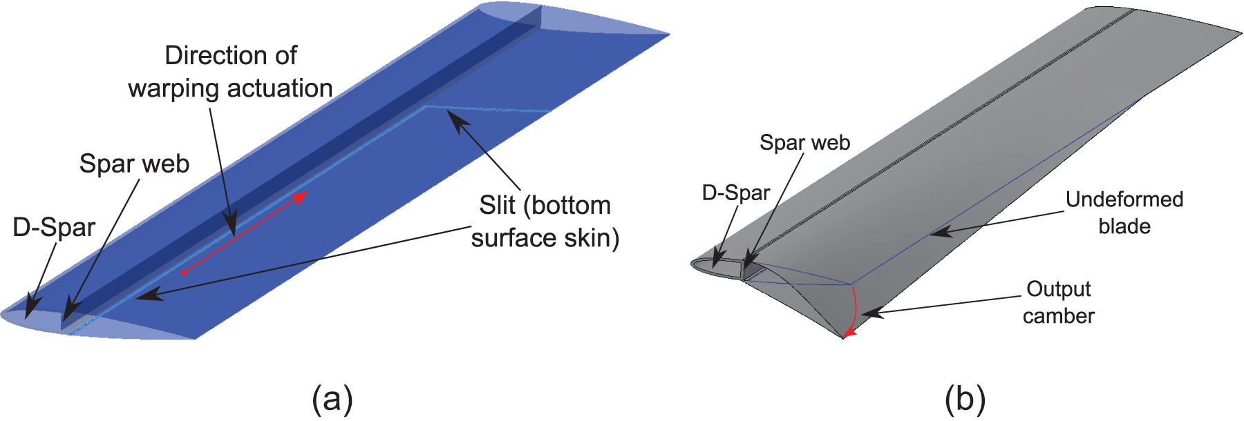
Annotated schematic of the undeformed and deformed configurations of the (a) undeformed state and (b) deformed state.
Before continuing with the detailed structural design of such a warp-induced variable camber blade, it is important to understand the potential aerodynamic benefits. This analysis is reported in Mistry and Gandhi (2012) and showed a potential hover power reduction of up to 18% in high and heavy conditions when the maximum camber was introduced at the root of the blade. The analysis also showed that spanwise camber variation, introduced in such a manner, was able to emulate the aerodynamic benefits of negative blade twist.
The present study focuses on the design, fabrication, and testing of a warp-induced variable camber rotor blade section. The following sections present the kinematic considerations of the designs followed by the details of the proposed design solution. Finally, the results of the benchtop test are presented along with finite element model validations and some parametric studies to understand the effect of external forces on the actuation characteristics of the design.
Baseline blade
The warp-induced active camber prototype was built using a section of a decommissioned CH-46 rotor blade (Figure 2). This hardware was donated by the US Navy Naval Air Systems (NAVAIR) Command’s Vertical Lift Center of Excellence (VLCOE). The pertinent dimensions of the donated blade section are listed in Table 1. As shown in Figure 2, the blade section has visible wear on the structure and hence was not deemed flight-worthy. Aside from these characteristics, the exterior coating of the blade leading edge was stripped down to a metallic substructure. The section aft of the spar wall is seen to be filled with a honeycomb filler.
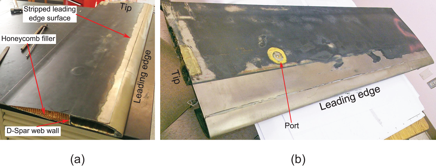
Isometric views of the top and bottom surfaces of the donated CH-46 blade section: (a) top surface and (b) bottom surface.
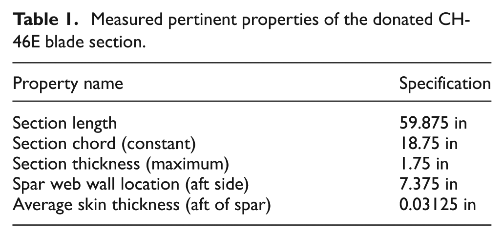
Measured pertinent properties of the donated CH-46E blade section.
Furthermore, the section provided originated from the tip of the blades is evident from the tip weight slots, as shown in Figure 3(a) (the removable tip weights are shown in Figure 3(b)). These tip weight slots were measured to extend a distance of up to 18.875 in into the blade. The blades incorporated a port (of unknown purpose) on the bottom surface close to the blade tip.
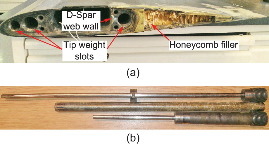
Detail views of the components of the blade tip: (a) detail view of tip and (b) tip weights.
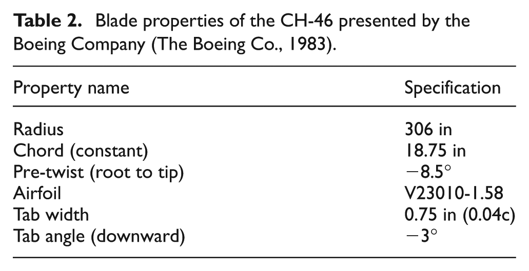
Based on the data presented in a report by the Boeing Vertol Company (The Boeing Co., 1983), the pertinent CH-46 blade properties are presented in Table 2. The chord value presented in the report matched the physical hardware dimensions. The report also referenced the inclusion of a 3° downward deflected tab with a width of 0.75 in. Note that blade section has a moderate amount of pre-twist.
Blade properties of the CH-46 presented by the Boeing Company (The Boeing Co., 1983).
Based on the information collected and the physical dimensions of the blade section, a computer-aided drafting (CAD) model of the hardware was created. The presence of the port and the tip weights aft of the web wall coincide with the intended location of the actuator intended to introduce warping and camber variation. Therefore, a 14.875 in spanwise section of the blade was removed from the blade (Figure 4). This reduced the available active camber section to 45 in. This section only includes a honeycomb filler aft of the spar wall, making this new configuration ideal for the application of camber actuation.
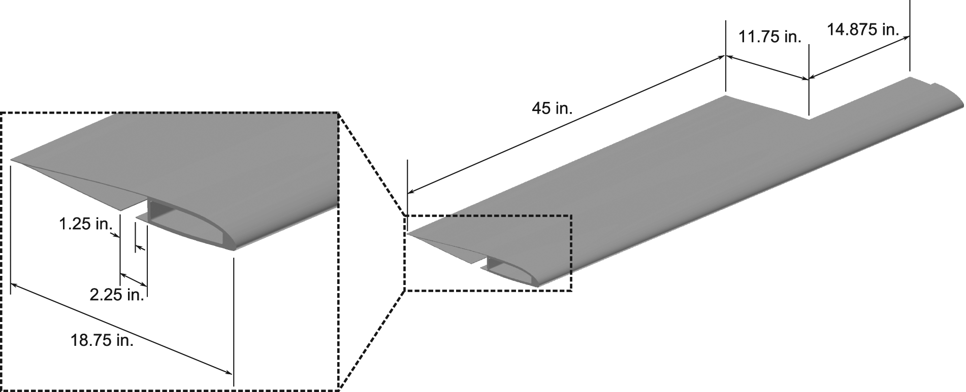
Computer-aided drafting (CAD) model of the modified section of the CH-46 rotor blade used for the current analysis.
A 1.25 in wide cut was introduced into the bottom skin, with the aft most cut of the slit set to be 2.25 in aft of the D-spar web wall, along the entire span of the active section of the blade (see Figure 4 inset). This allowed room for placement of the interior actuation structure and for the chordwise motion of the lower skin (an explanation for the requirement of chordwise motion is explained in the following sections). A CAD representation of the final modified blade structure (with dimensions annotated) along with the details of the slits cut into the bottom skin is shown in Figure 4 (note the honeycomb filler is not shown in the CAD model). This is the starting point of the design and analysis conducted as part of the present research. While the report presented by the Boeing Company (The Boeing Co., 1983) included macro dimensions of the rotor system, information regarding the specific materials (and layup) used in the CH-46E blade construction was not available in the open literature.
Design guidelines
A set of guidelines used in the development of a feasible design are listed as follows:
Entire actuation system should fit within the confines of the section of the blade aft of the D-spar web wall.
System should require only a single actuation input (minimize complication).
The design should allow for a minimum of 0.1 in of input spanwise warping.
Design should incorporate features, which minimize the possibility of system jamming.
Effect of actuation boundary conditions
The main purpose of the presented analysis was to determine the kinematic behavior of the blade to a given input warping. The secondary purpose was to analyze the effect of various actuation schemes (via the use of corresponding boundary conditions). While the outer cut of the slit in the blade skin was placed at a distance of 2.25 in aft of the spar web wall, in order to allow for the proper transfer of forces into the skin, the line of actuation was set to be at a distance of 2.5 in from the spar wall (Figure 5). Doing so allows for a buffer space of 0.25 in from the line of action to the edge of the skin, which permits placement of holes in the skin for attachment points, while minimizing the risk of tearing the skin. Since the actuation kinematics are based on the location of the line of action, a finite element model with a representative cut placed at the 2.5 in distance from the spar web wall was used for the preliminary kinematic analysis presented in this section. A model of only the active section (the region aft of the spar web wall) was used to reduce the number of elements required, thereby allowing faster computation. The material properties used here are arbitrary (the model uses the average modulus of aluminum) since only the kinematic relationship, and not actuation force, is being considered.
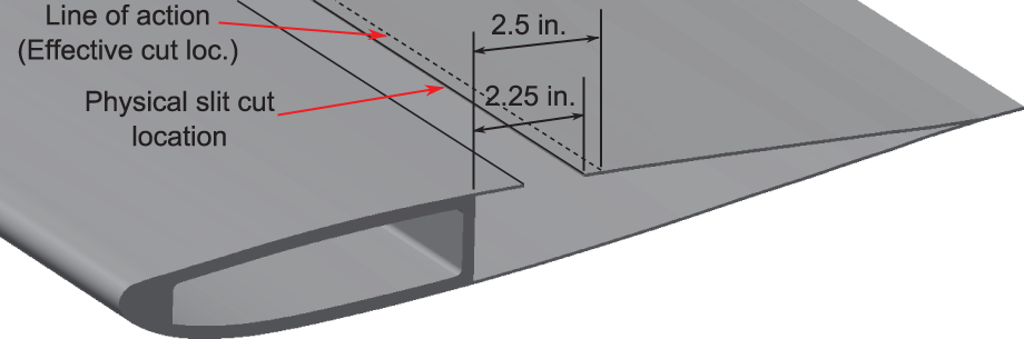
Schematic showing the line of action location (effective cut location).
Three cases were analyzed to represent three different actuation schemes. For all three cases, the spar web wall is considered to be clamped (to represent the rigidity of D-spar).
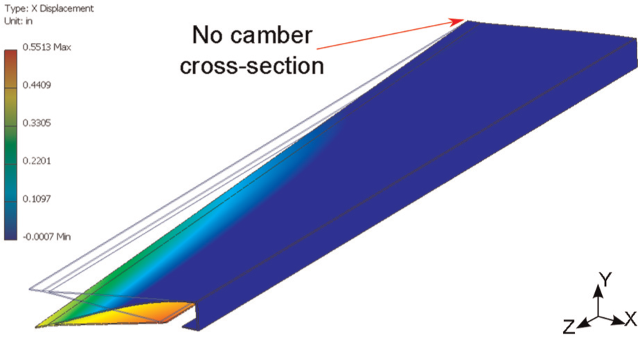
For case 1, the lower surface skin at the slit is constrained to move only in the spanwise direction. Furthermore, the zero camber cross-section is restricted from moving within the blade cross-section plane. This boundary condition is similar to that presented by Mistry, 2008; Mistry et al. (2011) in their variable twist prototype. In this configuration, the input actuation is a specified warping of the lower surface skin at the slit by 0.1 in (toward the zero camber cross-section). The resulting out-of-plane deformation (in the thickness direction, y) is presented in Figure 6. As can be seen from the figure, this actuation input and displacement constraints do not produce the desired camber variation. This is the result of over-constraining the motion of the slit (specifically the line of action).
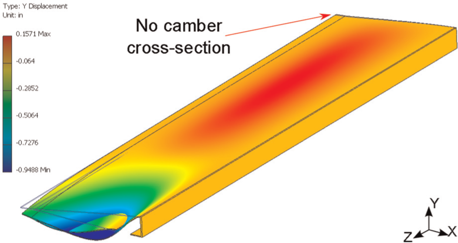
Calculated vertical deformation with applied case 1 boundary conditions.
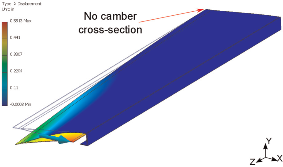
Case 2 encompasses all boundary conditions specified for case 1 with the exception that the lower surface skin at the slit is now allowed to move in the chordwise and spanwise directions. Based on these boundary conditions, the out-of-plane deformation (along the y direction) is presented in Figure 7 (with contours marking the chordwise motion, that is, along the x-axis). A smooth camber variation is observed along the span. Also shown in the figure, for a 0.1 in warping input, the slit undergoes 0.55 in of chordwise motion at the maximum camber cross-section. The chordwise motion varies linearly along the span of the blade (with the no-camber cross-section having zero chordwise motion).
Calculated chordwise deformation with applied case 2 boundary conditions.
Figure 8 presents a schematic diagram highlighting the effect of restraining the chordwise deformation on the overall camber shape. The tip section is seen to undergo an undesirable “potato chip” like deformation, which would prevent its effective operation as a cambered airfoil. This phenomenon is largely attributed to the boundary constraints. Based on the observations, it is clear that the kinematic relationship of input warping to chordwise motion must be considered for a desirable variation of camber along the blade.
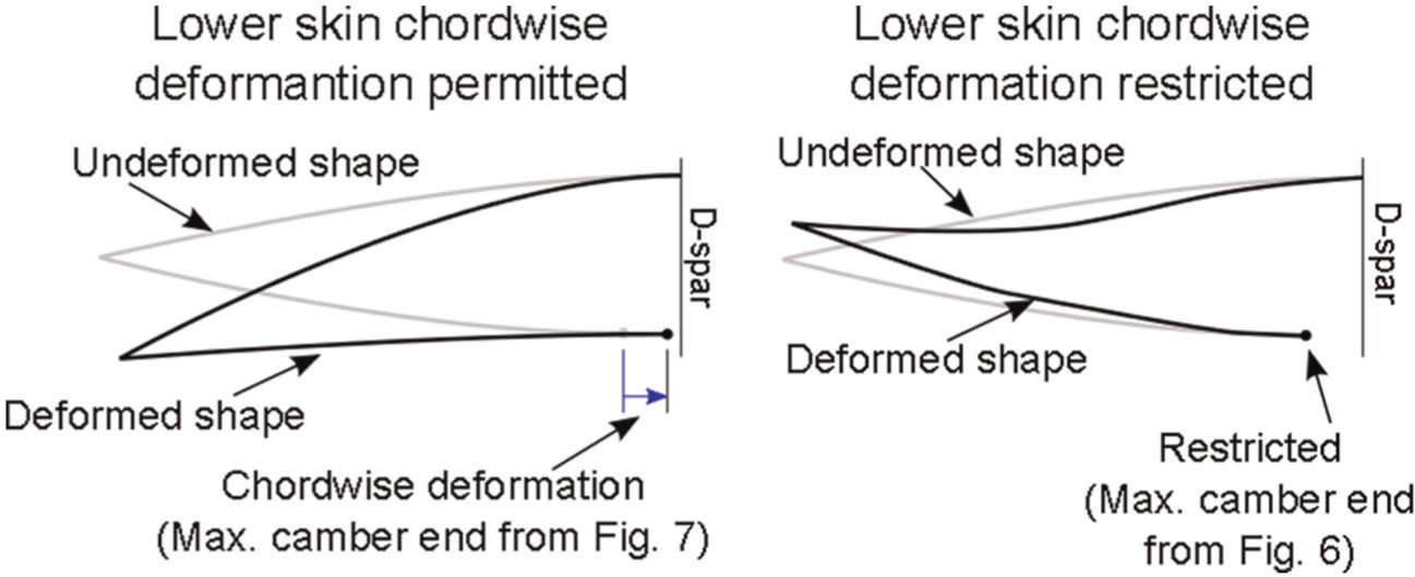
Schematic representation of the effects of chordwise slit deformation due to warping.
Case 3 has similar applied boundary conditions in that the lower surface skin at the slit is only allowed to move in the chordwise and spanwise directions while the zero camber cross-section is not allowed deformation in the plane of the cross-section. The difference however is the application of the input displacement. For case 3, instead of an applied warp input along the slit, the maximum camber end of the slit is subjected to a chordwise motion equal to 0.55 in. The resulting chordwise displacement field is presented in Figure 9. Comparing Figure 7 to 9, it can be clearly seen that the deformation in the blade is comparable. In fact, in this particular case, the spanwise motion of the slit (warping) was calculated to be approximately 0.1 in (not shown in figures). Therefore, this method proves to be an alternative method of actuation wherein instead of input warping, the skin is actuated to move in the chordwise direction. While case 3 presents an interesting alternative to actuating the blade camber (compared to case 2), the actuation system development presented in the proceeding sections follows the scheme presented by case 2.
Calculated chordwise deformation with applied case 3 boundary conditions.
Actuation structure design
As observed in the previous section, it is imperative that the actuation structure allows for the chordwise motion of the lower surface skin along the length of the slit in conjunction with the warping input in order to produce a smooth cambered airfoil profile. However, in operation, a rotor blade experiences significant inertial and aerodynamic forces. Therefore, rather than the actuation mechanism merely allowing for chordwise motion, it is preferable instead to ensure that the lower surface skin at the slit follows the precise combined motion along the span (warping) and in the chordwise direction. Figure 10 presents a schematic of the kinematic relationship that must be enforced by the actuation structure in order to produce the desired camber variation. In order to realize this requirement, a simple 2-bar linkage design was developed.
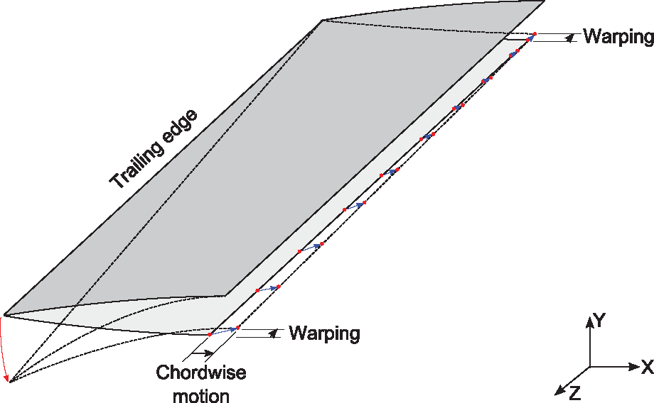
Schematic representation of the spanwise distribution of the required chordwise motion of the slit.
Figure 11 presents a schematic of the actuation frame concept along with key dimensions annotated. This arrangement consists of two linkages affixed to each other via a hinge (point B). The larger link (AC) is attached to the lower surface skin, aft of and parallel to the slit. One end of this linkage (point A) is constrained to move only in the spanwise direction, whereas the other end (point C) is free to move in the plane of rotation about point A (this is equivalent to moving in the X–Y plane as marked in Figure 11). Link AC has a length of l and is equal to the length of the active camber section (in the case of the present prototype: 45 in). The second smaller link, BD, has a length of lf and is oriented at an angle θf0 from the skin slit in the undeformed configuration. While it shares hinge point B with the larger frame AC, the other end (point D) is pinned to the spar web at a spanwise distance d and chordwise distance h from point B in the undeformed configuration. Note that distance of point D from point A (lD) has to always be greater than lB for the system to work as prescribed. The end result of this arrangement of linkages ensures that as the skin (which is rigidly attached to frame AC) undergoes the prescribed warp input of xA, it simultaneously undergoes a linearly varying chordwise motion reaching a maximum at point C of yC. The deformed configuration is shown in the figure for comparison. Point C corresponds to the maximum camber end of the active camber section.
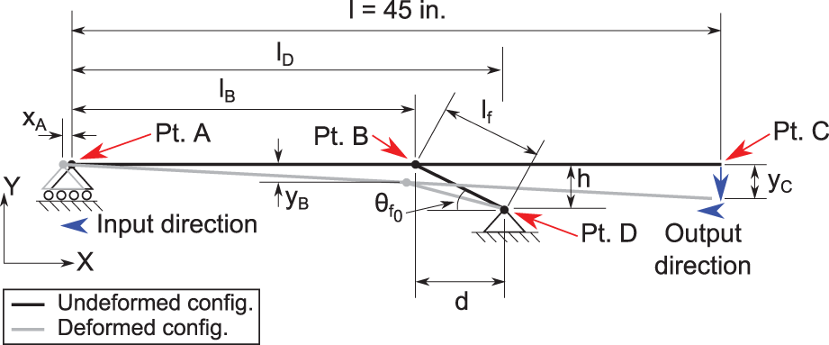
Actuation frame design schematic annotated with pertinent dimensions.
Equation (1) presents the kinematic equations corresponding to the system schematic presented in Figure 11. Recall the line of action was set to be at a distance of 2.5 in from the spar wall; however, in order to provide room for the structure (including hinges and fasteners), h was set to be 1.875 in. With this constraint, the only two parameters that were unknown were lf and lB. For the current design, in order to ease the machining requirements, the lengths of lf and lB were limited to integer values. lB was parametrically varied from 12 to 36 in with 4-in increments, whereas lf was varied from 3 to 8 in with 1-in increments. The problem then reduces to find the right combination unknown lengths that would produce required motion of yC of 0.55 in for a given warp xA input of 0.1 in
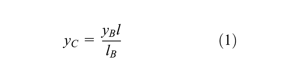
where
Since there are two unknowns in the above equation, there exist, in general, an infinite number of solutions. However, due to the physical limits placed on the maximum and minimum values of lf and lB and the discretizing of the possible solution space, a visual approach was used to pick the design configuration. Due to manufacturing constraints, it was generally preferred to have point B to be around the center of frame AC (corresponding to a value of lB in the vicinity of 22.5 in). Figure 12 presents the variation of the yC value as a function of lf for a varied range of lB. Based on the design guidelines, a length of lB of 24 and 5 in for lf was picked from the possible configuration within the design space (marked as solid black circles in Figure 12). As shown in the figure, this value is marginally lower than that for the required chordwise displacement. However, due to discretization of the design variables, this was the closest configuration. For future designs, the unknown lengths can be more finely tuned for a more refined configuration.
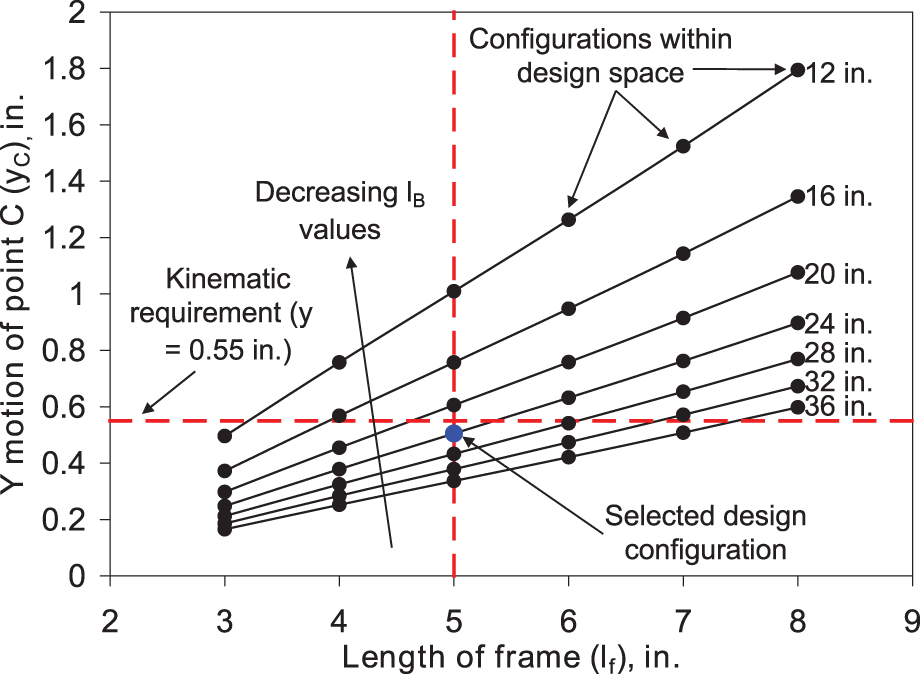
Actuation frame design selection chart for dimensions lf and lB given a warp input of 0.1 in and requiring an output of up to 0.55 in (chordwise motion).
In the design presented above, only one linear actuator is required to introduce a warping input, as the structure itself ensures both the chordwise motion and warping of the lower surface skin aft of slit. This feature simplifies implementation in a rotor blade.
Prototype design and construction
Having defined an actuation structure design, which would satisfy the kinematic requirements, the study proceeded with the detail design and construction of the variable camber prototype. The following sections consider the specific components of the prototype.
Blade skin
Figure 13 shows the honeycomb filler present in the baseline blade aft of the spar. The honeycomb filler was removed starting at the skin slit and continuing aft toward the trailing edge. A combination of hacksaws and power tools was used to remove the filler.
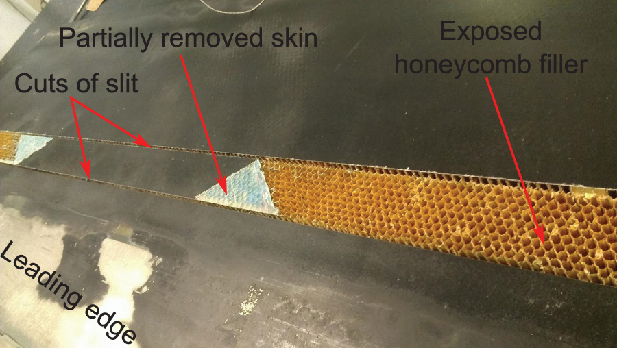
View of partial skin removed showcasing the honeycomb filler used in the construction.
Figure 14 shows the lower surface of the skin aft of the slit collapsed after removal of the honeycomb core. A thin section of honeycomb is still seen attached to the skin, the remnants being a result of efforts to ensure no damage to the skin during the honeycomb removal process. Honeycomb removal was especially difficult in the low thickness region in proximity of the trailing edge. The top and bottom surface skins converge at the trailing edge to form a 3% chord tab, which is significantly stiffer than the rest of the skin.
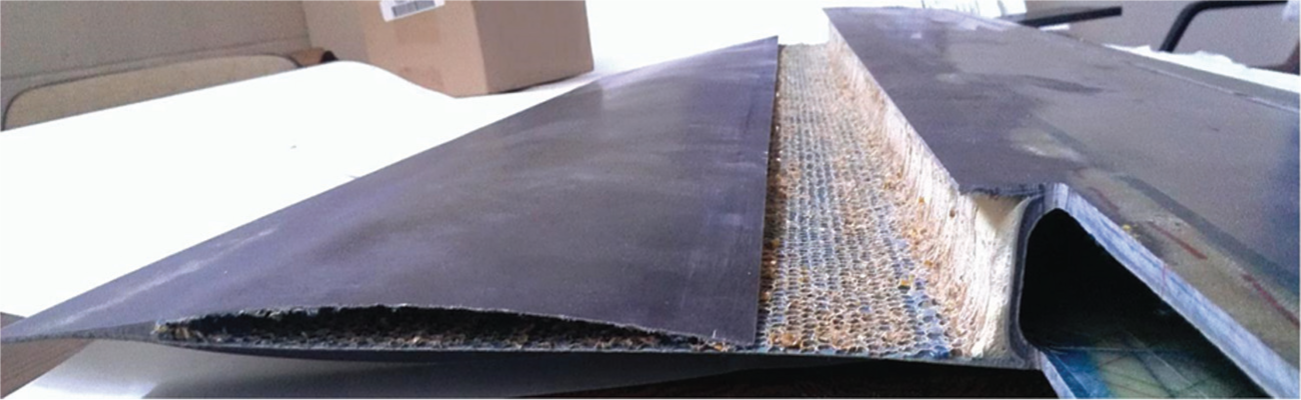
Exterior view of the blade skin aft of the D-spar web wall with the honeycomb removed.
Actuation frame
The actuation frame schematic design presented in the previous section was realized as a three-level sandwich structure (Figure 15). This provides increased flapwise bending stiffness while allowing for hinges to be securely fitted between levels 1 and 3. All three levels are sandwiched together via the use of an assembly of bolts and nuts. As shown in Figure 16, level 1 consists of a 1.5 in wide and 0.125 in thick plate with simple clearance holes intended for rivets, and countersunk holes intended for bolts, which will compress all three levels together. This is the level, which is rigidly attached to the lower surface of the skin close to the slit (the skin has a corresponding rivet hole pattern drilled into it). Similar to level 1, level 3 consists of a plate with simple clearance holes; however, this plate has a smaller width (1 in compared to 1.5 in for level 1). Both these levels have a span length equal to that of the active camber section (45 in).
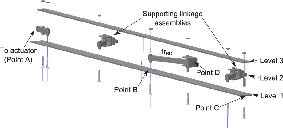
Exploded view of the actuation frame structure.
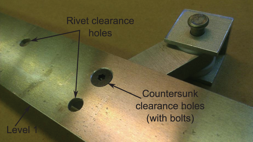
Detail view of the outer surface of level 1.
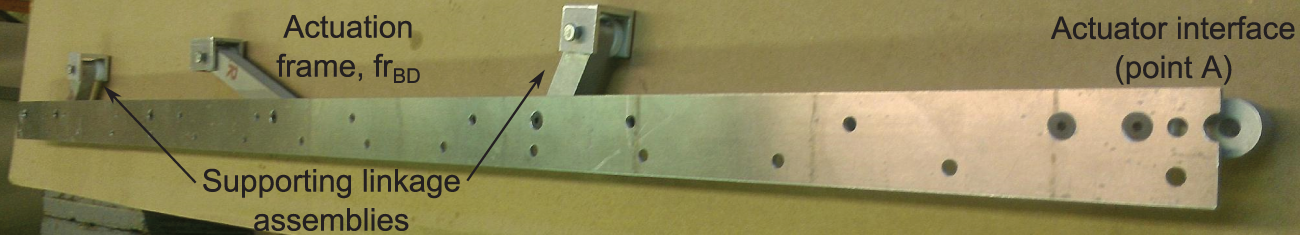
Level 2 consists of seven spacers, which maintain the distance between levels 1 and 3. Three of these spacers act as hinges for the actuation frame BD (at point B) and two supporting linkage sub-assemblies. Another two spacers act as anchor points for the interface between the actuation structure and the actuator (at point A). Unless otherwise specified, all the linkages shown here have a 0.5 in by 0.5 in square cross-section with 0.3125 in diameter holes at the connection points (this is an over-design to ensure the current assembly is failsafe). The actuation frame BD sub-assembly consists of the linkage itself and a supporting structure for point D (which includes a hinge comprising of a clevis pin), as shown in Figure 17.
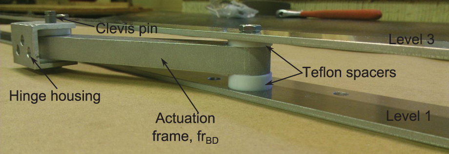
Detail view of the actuation frame BD.
The two supporting linkage sub-assemblies (Figure 18) are intended to provide bending load support (in the flapwise direction) to the actuation frame. These sub-assemblies do not affect the kinematic characteristics of the actuation frame at all. They contain a 2-in-long linkage connected to a hinge housing (similar in design as the actuation frame), which is affixed to a commercially available linear bearing. As the actuation frame undergoes motion, the hinge housings of the supporting linkages are allowed to slide along the linear bearing. These two sub-assemblies are located at a distance of 13 and 40.5 in from the actuation interface location (point A). The placement of these assemblies was to achieve a relatively equitable distribution of bending loads.
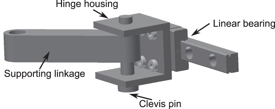
Detail view of supporting linkage sub-assembly.
The actuator interface comprising of a bar with two spacer slots is shown in Figure 19. This structure was designed to provide continuity of the load path from the actuator to the actuation frame structure. Note that between any two sliding surfaces, Teflon spacers were sandwiched to provide some relief to internal friction forces while allowing for a snug fit of the components.
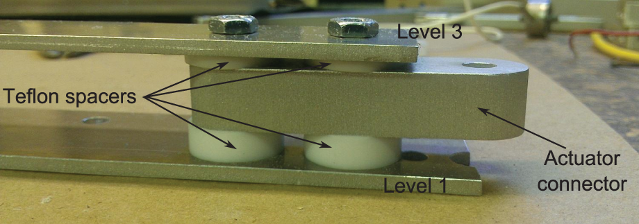
Detail view of actuator interface (at point A).
Figure 20 presents a view of the final assembled actuation frame assembly (without the linear bearing of the supporting linkage sub-assemblies) (note the clearance holes on the top surface). These are the rivets locations, which will connect to the lower skin of the blade section.
View of the completed actuation structure assembly.
The entire actuation frame structure is affixed to the internal spar web wall using bolts, which run through the spar itself (using clearance holes in the spar wall). As shown in Figure 21, a mounting plate is placed along the surface of the spar web wall on the interior of the D-spar. This plate contains threaded holes through which the respective bolts of the various components (either for the actuation frame hinge housing, point D, or the supporting linkages linear bearings) are affixed. The components of the actuation frame structure were built using a combination of water-jet and traditional milling and lathe manufacturing processes.
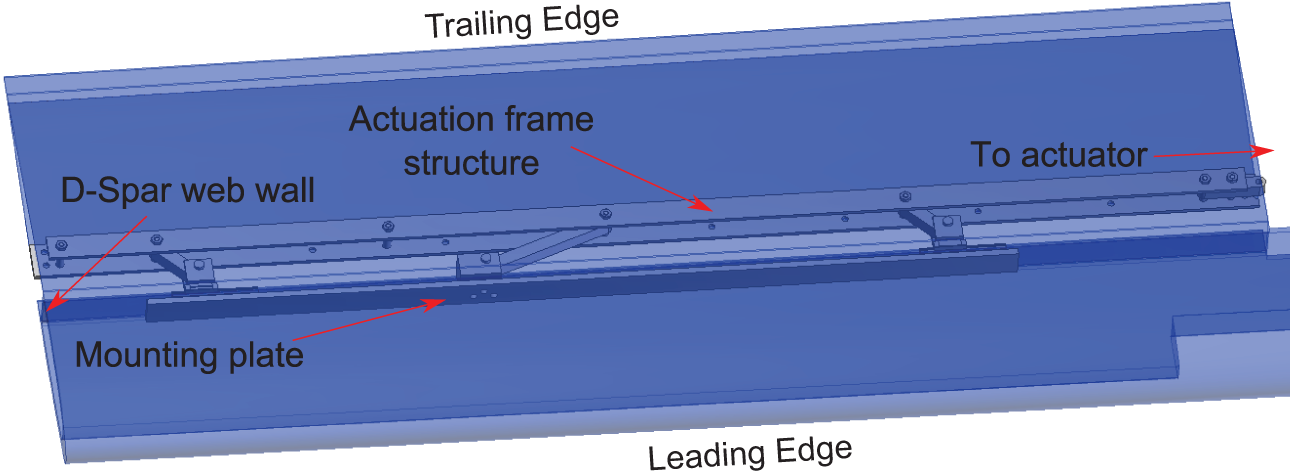
Schematic showing the actuation structure spar attachment assembly.
Actuator sub-assembly
The actuator sub-assembly, as shown in Figure 22, consists of the actuator, sensors (load cell and the embedded linear potentiometer in the actuator), and supporting elements that ensures only pure spanwise warping input. Since the existing blade spar wall was removed for this section of the blade (due to the presence of tip weight slots and bottom surface port), a new replacement spar was affixed to which all the components of the actuator sub-assembly are attached. The replacement spar is attached to the D-spar walls using three mounting blocks and is a retrofit measure for this specific prototype. Active camber blades designed from the ground up would have the actuator directly mounted to the actual blade D-spar web wall in the non-morphing section.
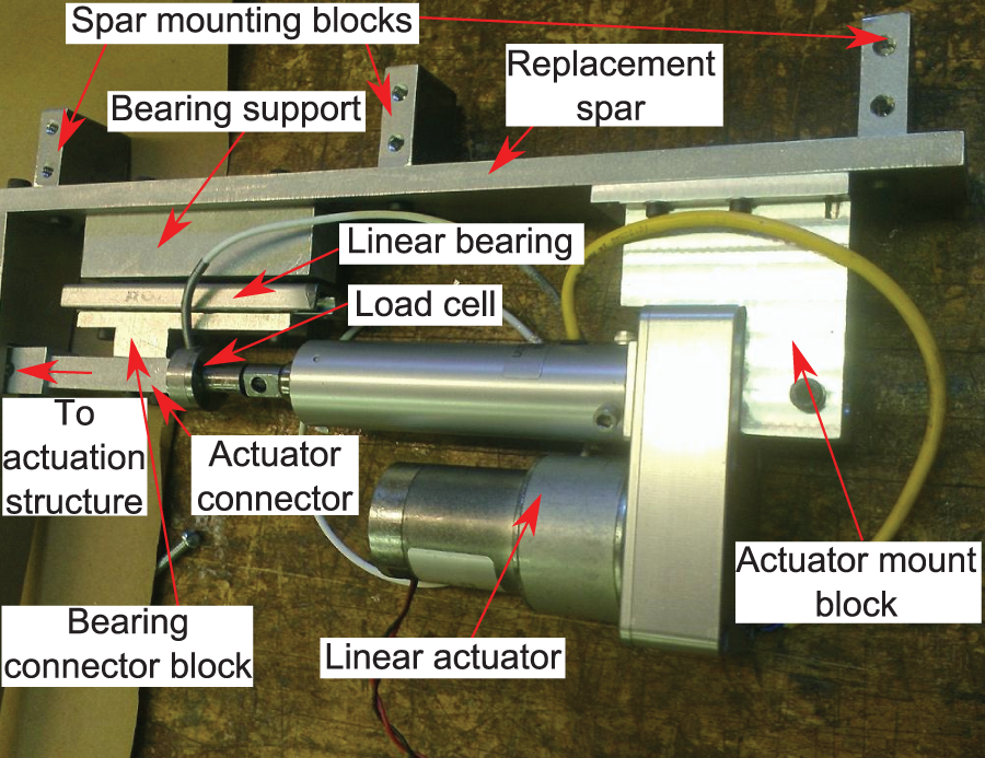
Actuator sub-assembly detail view with annotations.
As shown in Figure 22, a load cell is positioned between the actuator and slide attach block. This assembly has been put in place to ensure that the load cell only measures (and therefore the actuator only exerts) the forces required along the spanwise direction. Furthermore, this arrangement also ensures that point A of the actuation structure (actuator interface bar) only moved along the spanwise direction as desired. In this configuration, any chordwise load experienced is transferred directly to the spar. Therefore, on full-scale blades, care is required to ensure that the spar is able to carry all the chordwise loads over the sections designed for camber morphing.
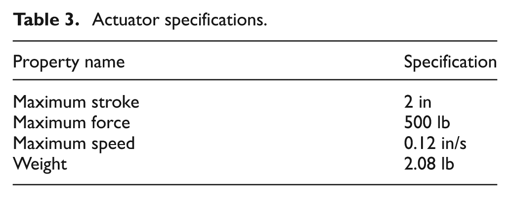
For the current study, an Ultra Motion Bug actuator was used and its specifications are provided in Table 3 (Ultra Motion, 2012). This actuator has been used by Hayden (2012) for the rotor testing of a variable chord helicopter rotor blade section and has thus demonstrated operational capability in the presence of a centrifugal field. The actuator has a built-in linear potentiometer, which was used to measure the actuator linear input. An Omega Engineering LC202-300 load cell was used for the current prototype. This model has a maximum load capability of 300 lb and was used without a signal conditioner.
Actuator specifications.
As highlighted in Figure 23 (which shows the completed internal structure assembly), the interface between the actuator sub-assembly and the actuation structure is a hinge. This allows for the frame AB of the actuation structure to rotate independently of the actuator. Aside from the actuator, load sensor and the linear bearing (which was made of hardened steel) all the components of the actuator sub-assembly were made using Aluminum-6061. Similar to the actuation frame, the components of the actuator sub-assembly were built using a combination of water-jet and traditional milling and lathe manufacturing processes.
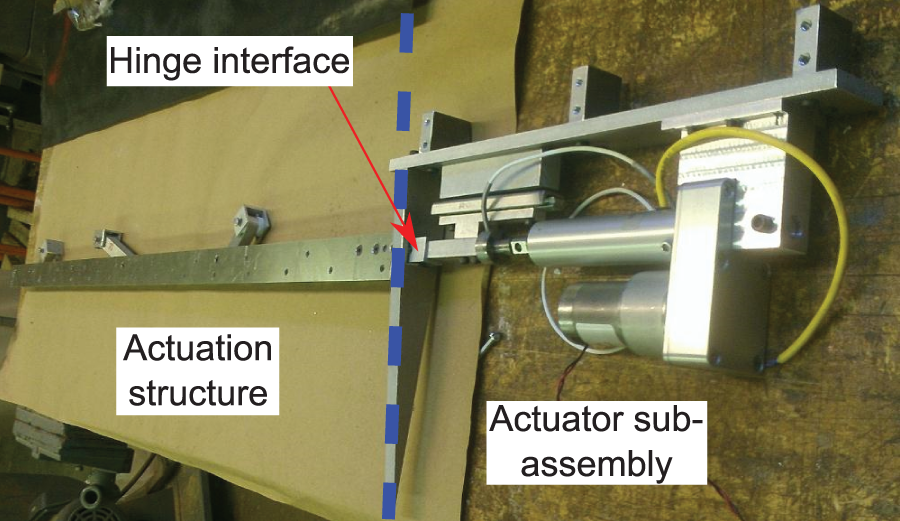
Completed internal structure with the actuator sub-assembly and the actuation structure highlighted.
Slit cover lip
The slit on the lower surface of the blade aft of the spar web was covered by a lip cover. This cover consisted of a 3.5 in plate (0.0625 in thickness), which was affixed to the D-spar such that it produced an overlap of 0.75 in over the slit in the undeformed configuration. During testing, the slit cover was not installed to provide access to the internal mechanism for troubleshooting. The slit cover can introduce surface sliding friction, which can contribute to an increase in actuation force requirement.
The finite thickness of the lip cover presents step discontinuities in the lower surface profile as seen by the flow. Its effect on the aerodynamic performance of the airfoil would need to be closely examined and its profile carefully designed to minimize performance penalties. It may also be possible to completely bypass the lip cover using, instead, some kind of stretchable skin across the slit.
Camber measurement
A digital angle gauge (digital level) was used to measure the camber deformation at the maximum camber end of the prototype. The gauge was attached to a level arm, which was hinged at the D-spar web wall and affixed to a point at the trailing edge of the blade cross-section. Since the point on the trailing edge undergoes translation within the cross-section plane as the section undergoes camber, the angle of the connector arm (connecting the spar web wall and the trailing edge point) was equal to the camber angle of the cross-section. Note that a slot was placed in the arm to remove any jamming that may occur during testing.
Final assembled prototype
Prior to completing the final assembly of the prototype, the actuator structure by itself was tested to visually observe the frame kinematics. Figure 24 presents the undeformed and deformed configurations of the actuation frame. As shown in the figure, the actuation frame undergoes both a spanwise translation and a linearly varying chordwise motion. This motion is directly transferred to the skin slit, which in turn results in the smooth camber variation.
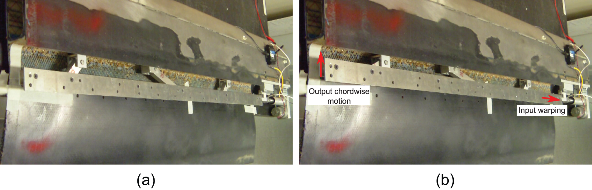
(a) Undeformed and (b) deformed configurations of the actuation structure only.
Figure 25 presents an isometric view of the final assembled prototype (with the lip cover affixed) in the undeformed and maximum deformed configurations. As can be seen, an input warping is capable of producing an approximately linear distribution of camber. Figure 26 presents an end view of the blade cross-section at the maximum camber end of the prototype at varying levels of camber. As can be seen in the figure, a significant variation of camber is possible with the current prototype. The details of the camber angles and the forces required to actuate the device are presented in the following sections.
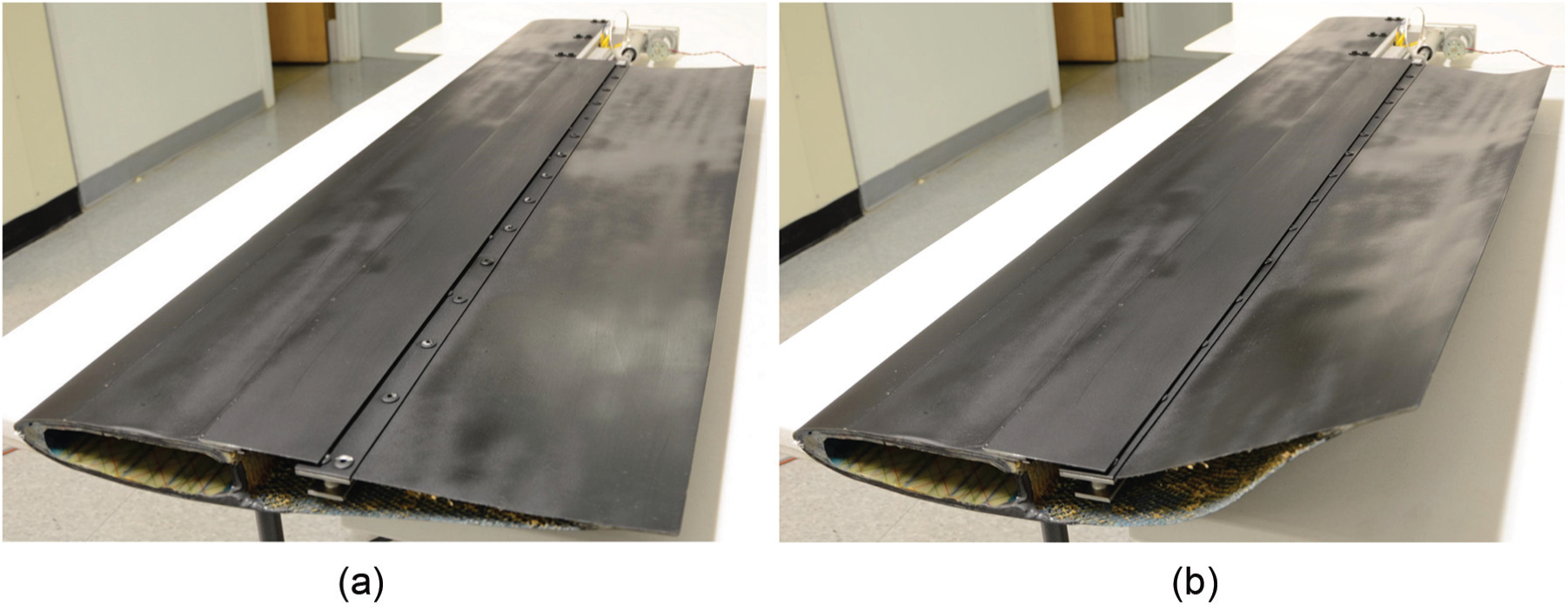
Isometric views of the completed prototype in two configurations: (a) undeformed configuration and (b) deformed configuration (maximum input warp).
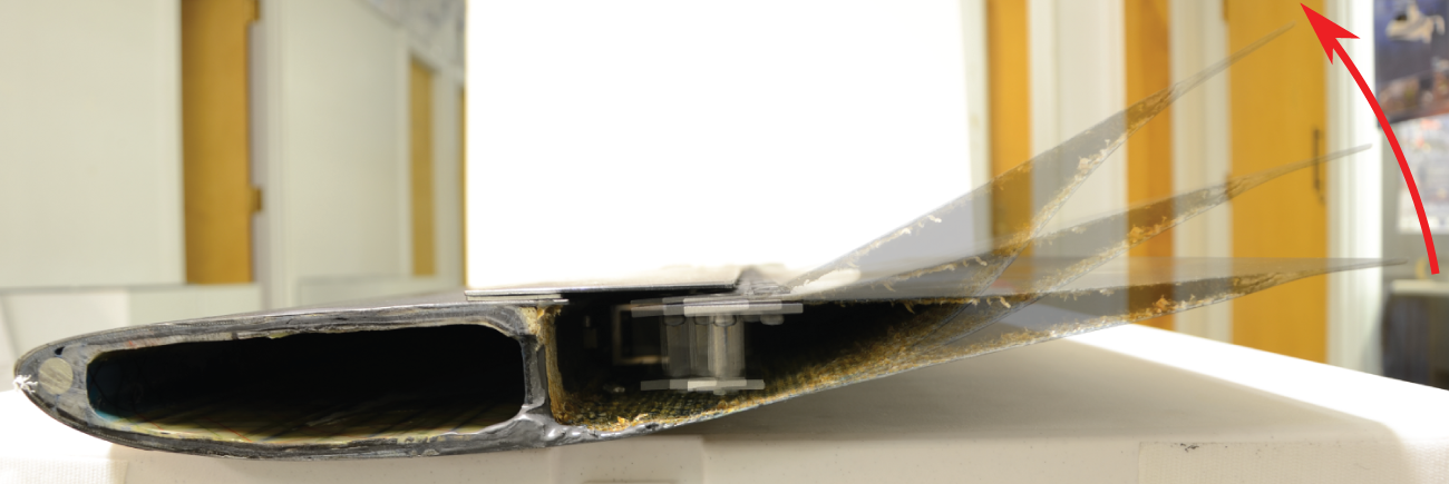
Front view of the maximum camber cross-section at varying levels of camber.
Finite element model details
A finite element model of the assembled prototype was developed using ANSYS® Ver. 14.0. The model includes the components of the actuation frame structure; appropriate boundary conditions (motion only allowed in the spanwise z direction, and rotations only about the y-axis) were applied at the actuation frame/actuator sub-assembly interface. The model comprises three different types of elements: Beam (BEAM188), Shell (SHEL181), and Brick (SOLID185) elements. The beam element used is the classic two-node element (with each node having 6 degrees of freedom (DOFs)). The shell element comprises four nodes, each with 6 DOFs. The brick elements with eight nodes with three translation DOFs at each node are only used when the effect of a filler in the portion aft of the spar is considered. Overall, the elements were sized to have element size of 0.2 in, resulting in a fine mesh.
The actuation frame structure is entirely modeled using beam elements. All components were made of aluminum, so a modulus of 10.6e6 lbf/in2 was used. Furthermore, all the elements were set to have the same cross-section of the physical parts they were representing, but details such as hinge holes and curved ends were not considered.
The skin and the trailing edge tab of the blade were modeled using shell elements with various layups (pertinent to the section under consideration). Based on a visual inspection of the skin of the prototype, it was observed that the skin was composed of approximately ±45° plies. A closer inspection reveals that the top and bottom skin, on average, each consisted of two-ply layers. Based on the average thickness of the skin of 0.031 in, each layer was assumed to be 0.016 in. Note that there were still thin layers of leftover honeycomb filler, which can contribute to errors in the stiffness of the skin. The fiber material was approximated as glass fiber and the material properties approximated for each ply are listed in Table 4. The moduli presented are based on the average values for glass fiber and glass fiber epoxy matrix found on MatWeb (2012). Furthermore, it was assumed in the finite element model that the shear, matrix direction, and thickness direction moduli values were those of the epoxy matrix.
Approximated skin ply stiffness properties (along ply axes).
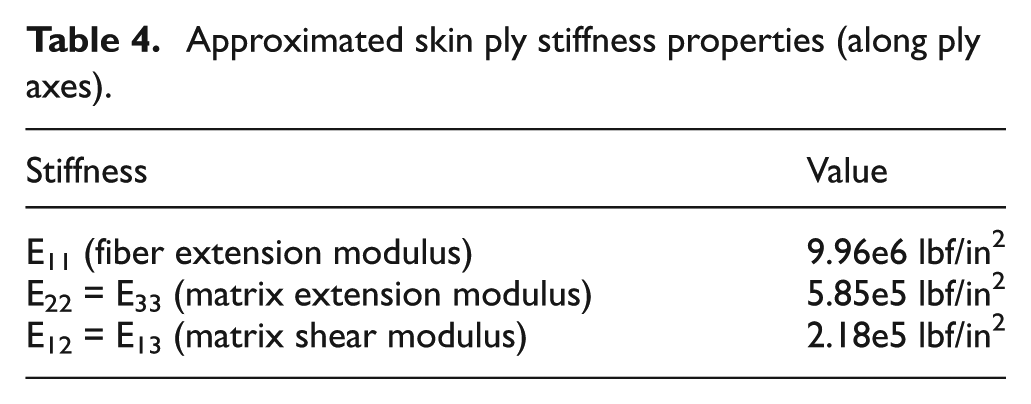
A visual inspection of the trailing edge tab reveals the bonding of both top and bottom skin layers in two sections of varying (tapered) and constant thickness, respectively. Correspondingly, in the finite element model, the tapered portion of the blade tab is modeled as a section of constant thickness (0.18 in), which comprises five layers. The top and bottom two layers correspond to the same layup as the top and bottom skins, respectively (i.e. ±45°, 2 plies), whereas the middle layer is assumed to be composed of epoxy filler and therefore is set to have the corresponding moduli (see Table 4). Finally, the constant thickness section is modeled as a composite comprising of four layers corresponding to the two layers of the top and bottom skins, respectively. This final layup is an approximation of the blade tab and is based purely on a visual inspection of the prototype. As the blade layup and material details were not available in open literature, such an approximation of the stiffness was used (correspondingly, this may be the source of some error in the calculation).
The nodes corresponding to the web of the D-spar section of the blade are clamped since the study is interested in examining the camber of the aft section. The input warping actuation motion, applied at the actuation structure/actuator sub-assembly interface, is up to 0.15 in (away from the maximum camber section).
Experimental setup
Figure 27 presents a schematic of the experimental setup used for the current analysis. The linear potentiometer (from the actuator) and the load cell signals were fed directly into the data acquisition transmitter unit (after digitization). The digital signal was then received by the data acquisition transmitter, which was then fed to a computer with the appropriate software (which also recorded the data for further post-processing). The digital level measurements were recorded manually into the computer. For the experiments, the D-spar was clamped for stability.
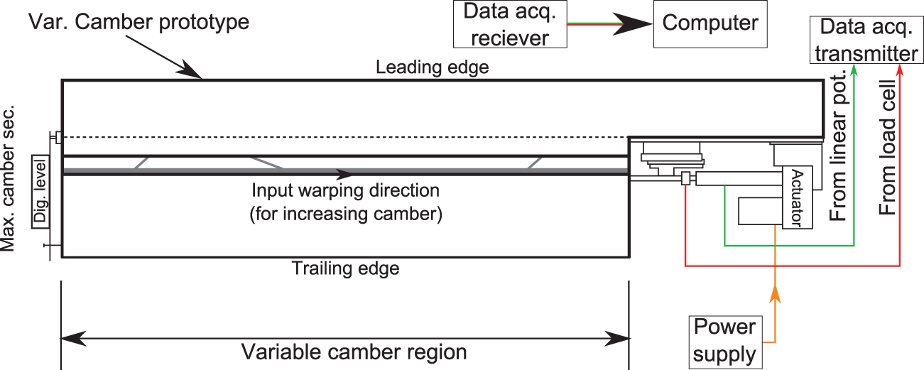
Schematic diagram of the experimental setup used.
Results
The following sections present experimentally measured data and compare to finite element model predictions. Furthermore, using the validated finite element model, a preliminary assessment is conducted to understand the effects of various external forces on the actuation behavior of the system. Finally, the effect of a filler or core in the region aft of the spar is considered.
Warp–camber relationship
Figure 28 presents the output maximum camber as a function of the input warping. The finite element results are seen to match the experimental results well. The small differences are attributed to slight imperfections in the hinge assemblies, which introduce some play in the system. Due to the high ratio of output to input, a small change in the frame movement relates to a relatively large change in the tip camber.
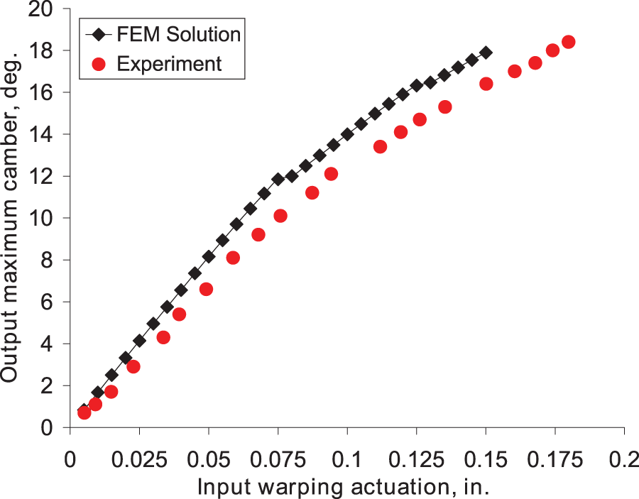
Comparison of the warp–camber relationship measured experimentally against the finite element model (FEM) results.
Warp–force relationship
Corresponding to the warp–camber relationship, Figure 29 presents the actuation force measured as a function of input warping. The finite element predictions and the measured forces show very good agreement up to 0.15 in of warp displacement. The sharp increase in measured forces for input warping greater than 0.15 in is due to internal binding between the actuation frame AC and the hinge housing of the supporting linkage. Since the finite element model does not account for contact, it is unable to predict the increase in force observed in the test. However, it should be noted that the system was designed for a maximum warping input of 0.15 in. The input warping beyond that value was simply to observe how the system would be behave if actuated beyond the design point.
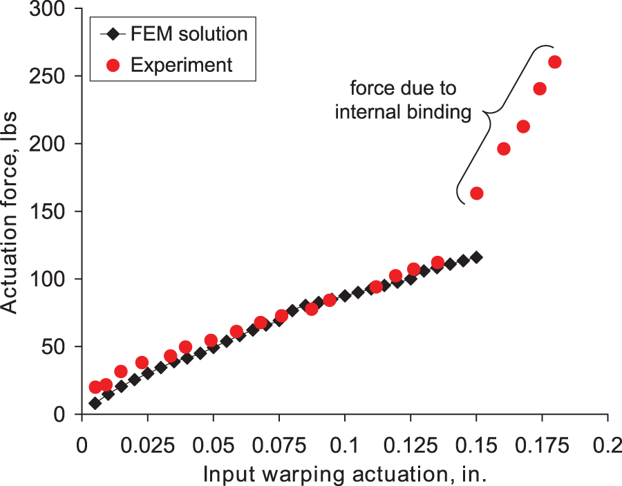
Comparison of the experimentally measured actuation force variation as a function of input warping against the finite element model (FEM) results.
Effect of applied loads
The following sections consider the effect of aerodynamic and inertial forces on deformations of the variable camber blade section. The effect of variations in boundary conditions and constraints is also considered. For the following sections, the finite element model results for the benchtop experiments are used as a reference case for comparison to the results of the various cases. For the proceeding analysis, the y-axis is oriented through the thickness (positive toward the upper surface), X-axis is oriented in the chordwise direction (positive toward the leading edge), and the Z-axis is oriented along the spanwise direction (positive is pointing toward the maximum camber section).
Centrifugal loads
The maximum camber section of the blade was assumed to be at a distance of 67.6 in from the center of rotation corresponding to the root cut-out location of the CH-46E rotor, as reported in Boeing Co. (1983) (Mistry and Gandhi, 2012 had previously shown aerodynamic benefits of having maximum camber at the inboard end of the blade). The quarter chord was placed along the radial axis from the center of rotation and the blade is assumed to have a zero angle of attack at the root cut-out. The mass distribution used in the finite element model is based on the physical prototype. The rotor speed was set to 263.7 r/min, which corresponds to that of the CH-46E (The Boeing Co., 1983). Case 1 presents the effect of centrifugal forces only on the blade behavior with warping input (i.e. the current variable camber prototype, with no modifications, on a rotor test stand in a vacuum chamber). Figure 30(a) presents an isometric view of the deformed configuration (with input warping and centrifugal forces) of the blade as predicted by the finite element model (the contours refer to the displacement along the y-axis). The presence of centrifugal force is seen to produce a bulge on the upper surface of the blade section at the zero camber end and a reduction in cross-section thickness at the maximum camber end, which changes the airfoil shape detrimentally. This cross-section thickness reduction is primarily due to the absence of a filler core in the current prototype.
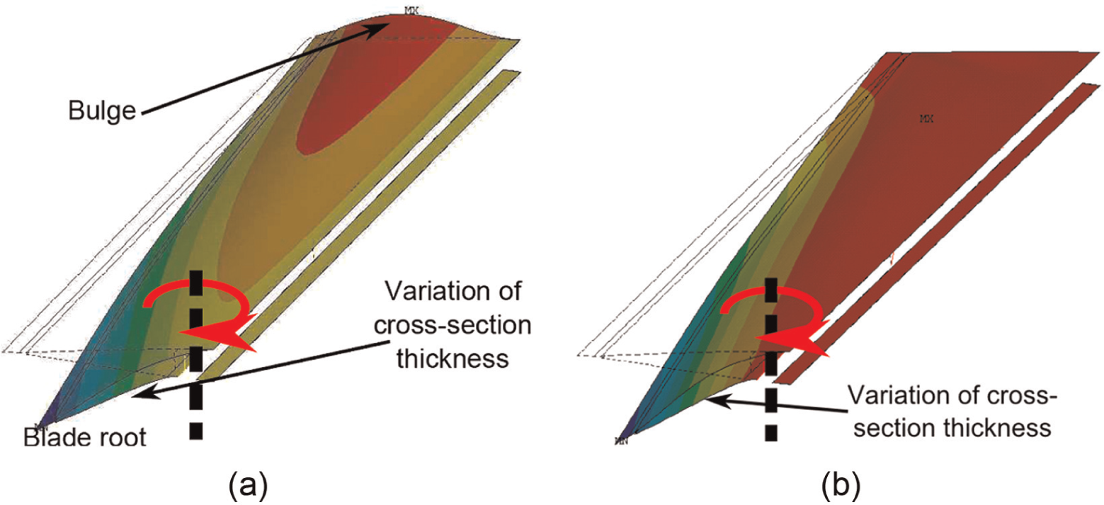
Isometric view of the displacement of the model nodes along the y-axis for the maximum input warping configuration for (a) case 1 and (b) case 2.
While the current prototype is a standalone proof-of-concept technology demonstrator, on a full-scale blade, the variable camber section would integrate into the non-morphing part of the blade. As such, the top surface at the zero camber end of the active camber section would be continuous with that of the passive portion of the blade. The effect of this continuity can be modeled via the application of boundary conditions wherein the nodes of the top surface of the skin at the zero camber cross-section are constrained for all 6 DOFs. The result of this boundary condition (case 2) is presented in Figure 30(b), which shows an isometric view of the deformed configuration of the blade at maximum warp input of 0.15 in. As can be clearly seen, the addition of the boundary condition on the upper surface at the non-morphing interface suppresses the bulge on the upper surface. However, it does not eliminate the reduction in cross-section thickness at the maximum camber end.
Centrifugal and aerodynamic loads
Case 3 considers the effects of representative aerodynamic loads applied to a rotating variable camber blade section with the continuity boundary condition of Case 2 applied. To approximate the effect of the aerodynamic loads, the aerodynamic hinge moment is calculated at 0.4 chord using XFOIL. These moments were calculated at a Mach No. of 0.2 (since it is proposed that camber be introduced at the inboard end of the blade) and a sectional angle of attack of 4°. In the finite element model, a distributed vertical force that resulted in the same moment at 0.4c was applied at the trailing edge nodes. Application of distributed pressures on the upper and lower surfaces lead to convergence instability issues for the finite element model so the approach described above was used just to get a quick approximation of the effect of aerodynamic forces on the behavior of the system.
Figure 31(a) presents the deformed configuration of case 3 with contours highlighting the y-displacement of the model nodes. As can be seen, the upper skin begins to dimple at the root with the addition of the aerodynamic load to the centrifugal loading. This effect is similar to that reported in Mistry (2008) and Mistry et al. (2011) for a warp-induced variable twist rotor section. In all cases 1–3 discussed above, the blade thickness varies to some degree when the cross-section is cambered due to the lack of a core (filler). Since camber variation is realized by means of warping of the bottom skin in the spanwise direction, a filler with low in-plane shear stiffness (to keep actuation forces to moderate levels) but high out-of-plane stiffness (preventing skin bulging, dimpling, and cross-section thickness variation) is desired. Case 4 considers the loading and boundary conditions of case 3 with the addition of a filler, which has a very high extension stiffness along the y-axis but has a relatively low shear stiffnesses. The filler material properties used for this case are listed in Table 5. While materials with such a combination of properties cannot be found, filler cores can be engineered to provide such highly anisotropic properties. For example, studies have considered cellular substructures for flex skins of morphing wings that provide very low in-plane extensional stiffness (Olympio and Gandhi, 2010), or in-plane shear stiffness (Asheghian et al., 2011; Olympio et al., 2010), while providing high out-of-plane stiffness to carry aerodynamic loads.
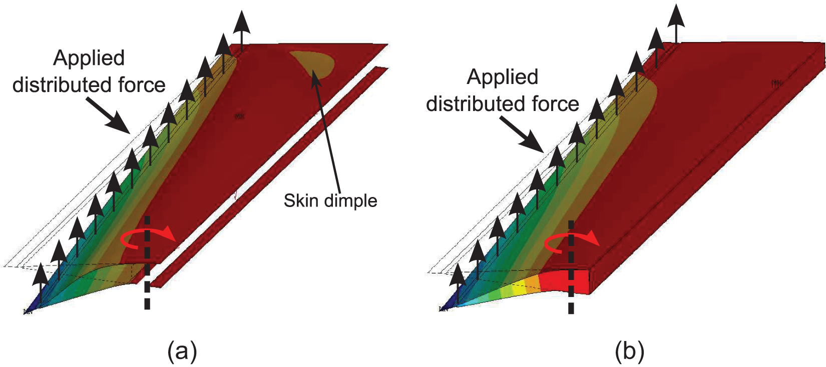
Isometric view of the displacement of the model nodes along the y-axis for the maximum input warping configuration for (a) case 3 and (b) case 4.
Representative stiffness of filler core used in case 4.
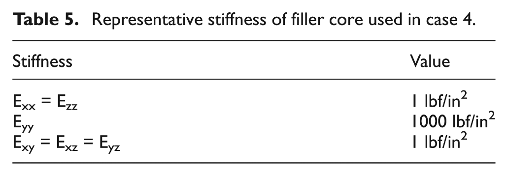
Figure 31(b) presents the deformed shape of the variable camber blade for case 4. No skin dimpling is observed on the top skin in the vicinity of the zero camber section. The variation of the blade cross-section thickness is also eliminated. However, an increase in actuation force requirement can be expected on account of the core.
Conclusion
This article focuses on the design, fabrication, testing, modeling, and validation of a spanwise variable camber section of a helicopter rotor blade. The design concept uses the warp–twist coupled effect of open section beams to realize blade camber. In particular, a slit is cut just aft of the spar web wall on the lower surface skin which when warped produces a spanwise distributed camber variation. The proposed design was implemented in a proof of concept prototype built using a 45 in span CH-46 blade section.
Kinematic analysis of the blade (using a finite element model) revealed the importance of allowing the chordwise motion of the lower surface skin at the slit. Restriction of the chordwise motion was shown to cause an undesirable “potato chip-like” deformation of the cross-section. Based on this analysis, an actuation structure was designed and built to satisfy the blade skin warp kinematics.
The actuation structure along with the actuator and sensors was built into the CH-46 blade section. Benchtop testing showed the capability of the prototype to produce up to 18° of camber (linearly distributed along the span) with a warping input of 0.18 in. The experimentally measured camber and actuation force requirement results were shown to compare well with the finite element model results.
This validated model was then used to conduct a parametric study to examine the effects of an applied centrifugal field and applied aerodynamic forces. The results showed that in the absence of a filler core when the lower surface skin at the slit was warped, the cross-section deformation was undesirable in the presence of inertial and aerodynamic forces. However, if a shear-flexible core (with high through-thickness stiffness) was used, the blade would produce smooth camber variation albeit at an expected increase in actuation force requirement.
Footnotes
Acknowledgements
The authors would also like to thank COL (ret.) Samuel S. Evans for his help in procuring the CH-46 blade section and the US Navy Naval Air Systems (NAVAIR) Command’s Vertical Lift Center of Excellence (VLCOE) for their donation of the blade section.
Declaration of conflicting interests
The authors declared no potential conflicts of interest with respect to the research, authorship, and/or publication of this article.
Funding
The authors would like to acknowledge the US Department of Defense for the National Defense Science and Engineering Graduate (NDSEG) Fellowship which funded the first author’s graduate studies.