
Abstract
Magnetorheological dampers have been widely studied as versatile real-time actuators for solving vibration problems in various structures and systems. However, the inherent time delay problem of magnetorheological actuators may cause performance degradation of semi-active control systems. The primary purposes of this article are to provide a comprehensive analysis on the time delay of an impact buffer system based on a magnetorheological damper and to propose compensation methods to reduce the time delay. To this end, this study evaluated the electromagnetic circuit in the magnetorheological damper and designed an advanced correcting circuit to improve the response time. The simulation results show that the proposed circuit reduces the time delay by 5 ms. Using a magnetorheological buffer system setup, its force response times were tested. The experimental results show that the electromagnetic circuit plays a significant role in the time delay and it is highly dependent on the effectiveness of the electric parts of the control hardware. Furthermore, a proportional–integral–derivative controller is able to reduce the time delay and improve the dynamic performance of the magnetorheological impact buffer system.
Introduction
Magnetorheological (MR) dampers have been effectively used for reducing seismic responses of civil engineering structures and controlling vibration responses of vehicles and other engineering systems where rapid responses are demanded (Lee and Kawashima, 2007; Ruangrassamee and Kawashima, 2001). Typical structural control systems consist of numerous components, such as sensors, amplifiers, filters, controllers, and control devices. Obviously, all these components require time to be properly activated, thus there exist inevitable time delays between input signals and output control forces. The time delay may cause performance degradation problems of control systems, particularly in semi-active systems where real-time controls are required. Hence, various methods have been proposed to compensate the time delay problems (Alkhatib and Golnaraghi, 2003; Bhardwaj and Datta, 2006).
Since Crosby and Karnopp (1973, 1974) first introduced semi-active dampers and semi-active controls, several investigations have been carried out to characterize the response time of the electrical and mechanical parts of MR damper based on semi-active systems (Goncalves et al., 2003, 2006; Koo et al., 2003; Zhu, 2005). Though the response time of MR fluid itself is 1–2 ms, the response time of MR devices is not as fast as anticipated because other factors (such as compliance of the system, control electronics) affect the total response time of MR devices (Goncalves et al., 2003, 2006). Christenson et al. (2008) measured the response time of a 200-kN commercially available MR damper from Lord Corporation, and it turned out to be approximately 30 ms, which is less than the response time of a 180-kN MR damper by Lord Corporation (i.e. 60 ms). Koo et al. (2006) experimentally studied the response time of an MR damper by considering the effects of the operating current, the piston velocity, and the system compliance. Occhiuzzi et al. (2003) defined three different time delays in a full-scale 50-kN MR damper system and carried out extensive semi-active tests and simulations to access the effects of time delays.
In an effort to address the time delay issues of MR damper systems, over the past decades, different control algorithms have been developed and investigated for MR damper systems. The clipped-optimal control (COC) was proposed by Dyke et al. (1996), and it was applied to a small-scale experimental building system equipped with MR dampers. Xu et al. (2003) proposed a semi-active control algorithm based on neural networks and applied it to a building structure. Cha and Agrawal (2011) developed the decentralized output feedback polynomial controllers based on a genetic algorithm, and they (Cha and Agrawal, 2012) applied it to a nonlinear highway bridge model and a large-scale three-story frame model. Besides, controllers based on fuzzy logic algorithms have been proposed and applied to civil structures and vehicle systems (Choi et al., 2004; Guclu and Yazici, 2008; Sun et al., 2005). Several advanced control algorithms have been proposed, such as the statistical process control (SPC) controller. Zhang (2012) implemented the SPC to civil structures without any controller or sensors.
Despite the fact that the response time of MR systems for civil engineering fields and suspension systems has been studied, the effect of time delay on the performance of semi-active control systems subjected to impact loadings has rarely been investigated. In their recent work, Wereley et al. (2011) and Singh HJ and Wereley NM (2013) studied an optimal control design of adaptive magnetorheological shock isolation (MRSI) mounts for drop-induced impacts and performed non-dimensional analysis of the system. The results showed that the time constant and the Bingham number, which is defined as the ratio of the yield force to the viscous force, are of utmost importance in effectively controlling the system response. Considering the extremely short time of the force control (less than 600 ms) in MR buffer systems under impact loadings, the time delay study would be critically important for the effect of the MR systems. Nonetheless, there exists little research on compensation methods for time delay in MR systems for such applications. Thus, this article focuses on the analysis and compensation methods against time delays of an MR buffer system under impact loadings. It evaluated the effects of the basic electromagnetic circuit as well as an advanced correcting circuit on time delays. In addition to the circuit analyses, the effect of driving electronics on the overall response time was also evaluated. The MR damper used in this article is a specially designed long-stroke MR damper, and the time delay of the MR buffer system was experimentally measured. Furthermore, a proportional–integral–derivative (PID) controller was designed to compensate the time delay in the real-time control system.
Experimental setup
Figure 1 shows an impact buffer system based on an MR damper, which is intended to control the damping characteristics continuously by varying the input power of the electromagnet. The experimental setup consists of an industrial control computer, a real-time simulation system (dSPACE), a current controller, and an experimental platform (Li et al., 2009). The damper is installed in shaft sleeves with a recoil mass, and the piston rod is connected to the ground mount.
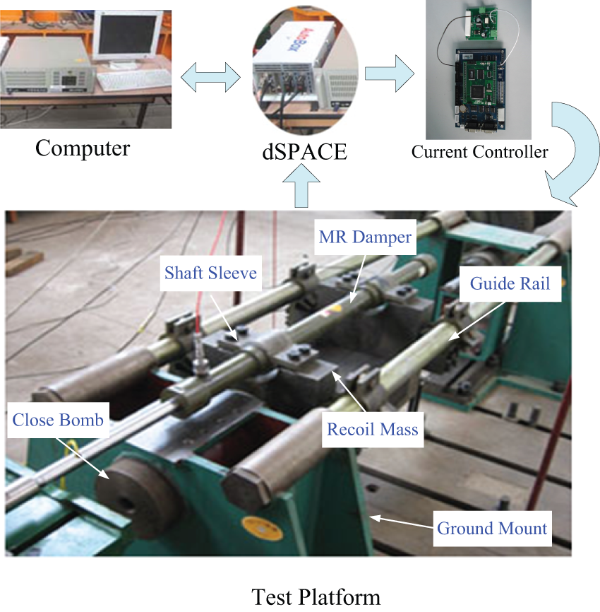
Impact test platform system.
During the experiment, the explosion of gunpowder in the close bomb produces a large impulsive force, which pushes the recoil mass along with the MR damper cylinder back along the guide rail. The elastomeric bumper is installed at the rear of the test setup to prevent the recoil from bumping into the test rig in a case that the recoil exceeds the maximum stroke length. The current controller is used to control the damping force according to the control input prescribed by the dSPACE control system, which is also used as the data acquisition system.
The MR damper in the buffer system works as a shock absorber, and it is used to dissipate energy of the impact loading. Thus, the impact loading within an extremely short time is transformed into small damping force acting on a long displacement. Such dynamics can be expressed as the following differential equation
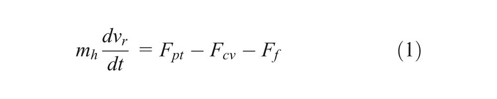
where
Agrawal and Yang (1997) defined the time delay as a summation of the fixed time delay and the time taken by actuators to build up the required control force. The fixed time delay, which includes the on-line data acquisition from sensors at different points of the structure, filtering, processing of data, calculation of forces, and transmission of the control force signals from computer to the actuator, is almost exclusively dependent on the effectiveness of the electric part of the control hardware. Thus, this study focuses on the total “process” time that requires building up the desired control force, which depends on the specific dynamics of actuators as well as the fixed time of the control hardware.
Electromagnetic circuit analysis
In this section, the research on the time delay starts with a simplified electromagnetic circuit analysis. Based on the simplified circuit analysis, an electromagnetic drive circuit of the current controller is investigated. A feasibility of reducing the time delay by modifying the transfer function of electromagnetic circuit is discussed.
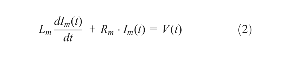
Basic electromagnetic circuit model
In order to illustrate the principle of the electromagnetic circuit for an MR damper, a basic model was first investigated. The electromagnetic circuit of an MR damper is generally simplified into an equivalent resistance and an equivalent inductance connected in series. The control current cannot make a sudden change because the inductance needs a time to store and release energy, which delays the “activation” of electromagnetic coil. Figure 2 illustrates an electromagnetic circuit of an MR damper by assuming
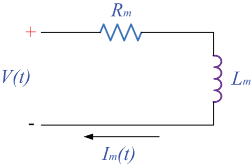
Electromagnetic circuit of MR damper.
If the loading voltage is a constant, the solution of the above equation can be given as
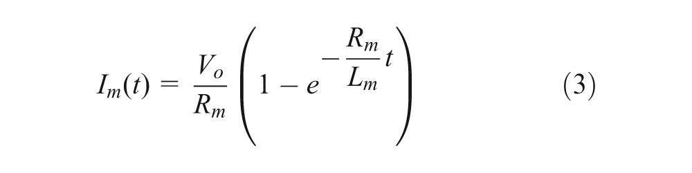
where
Figure 3 shows the simulated results of the relationship between the equivalent resistance
Resistance versus time.
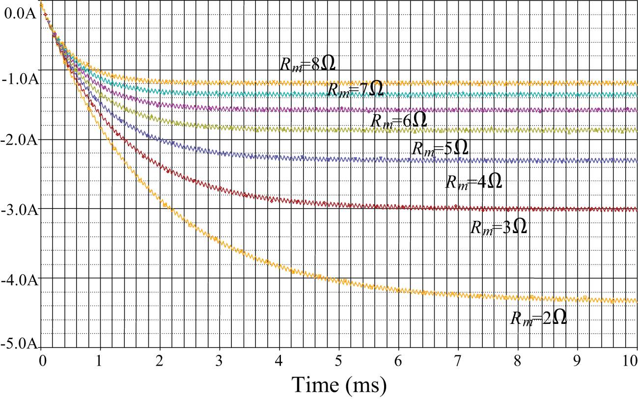
Inductance versus time.
Current controller
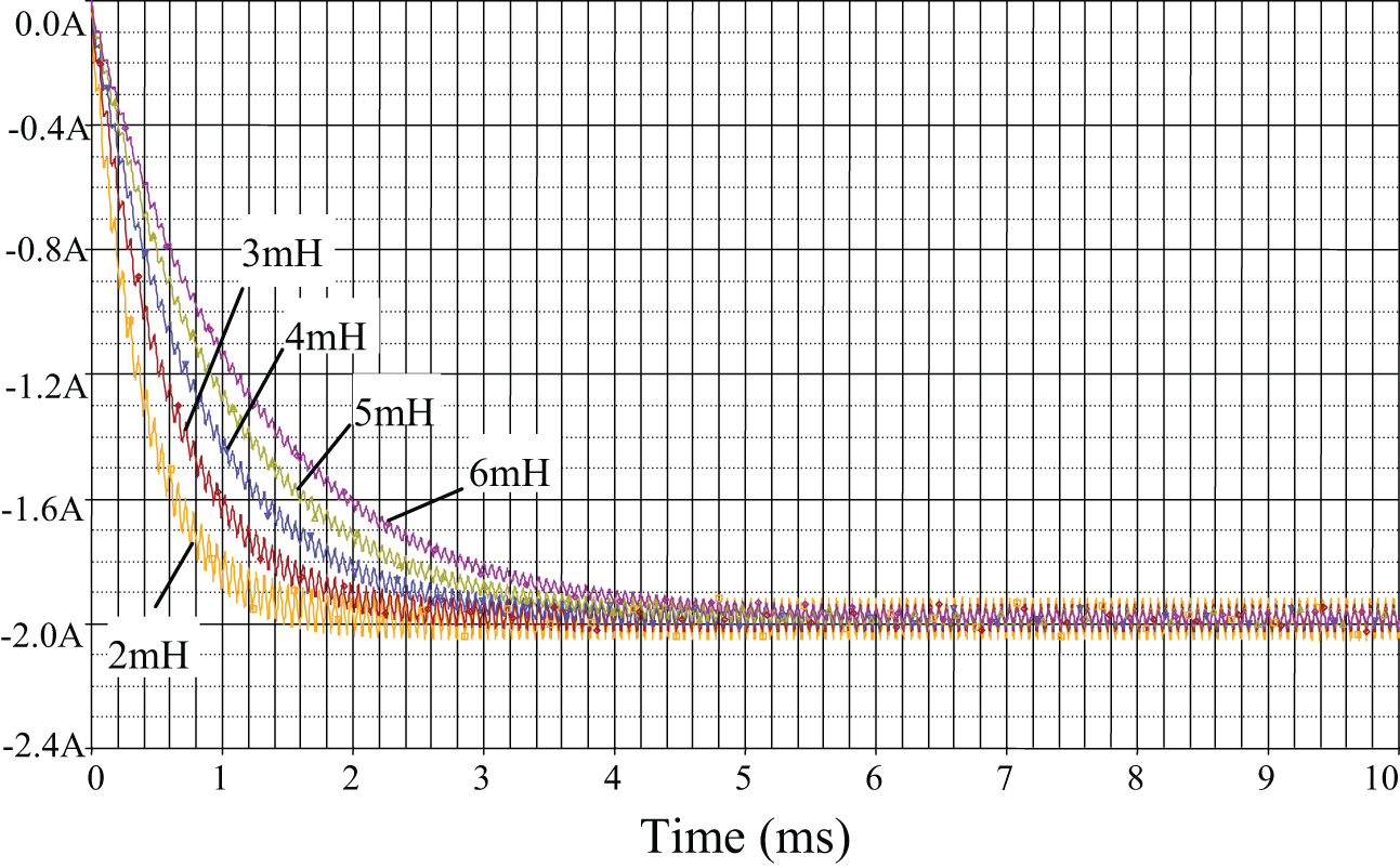
In order to control the output force of an MR damper, the input current must be continuously adjustable by a current controller. In this article, the pulse width modulation (PWM) current drive technology is adopted to control the current on the electromagnetic coil of the MR damper, which generates magnetic fields and controls the output damping forces. Figure 5 shows a current controller that includes a current driver and a digital signal processor (DSP) controller. The PWM signal
Current controller.
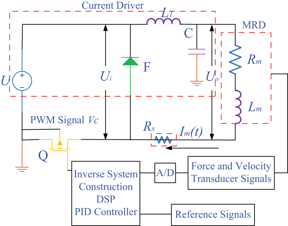
Schematic of MR control system.
The PWM signal
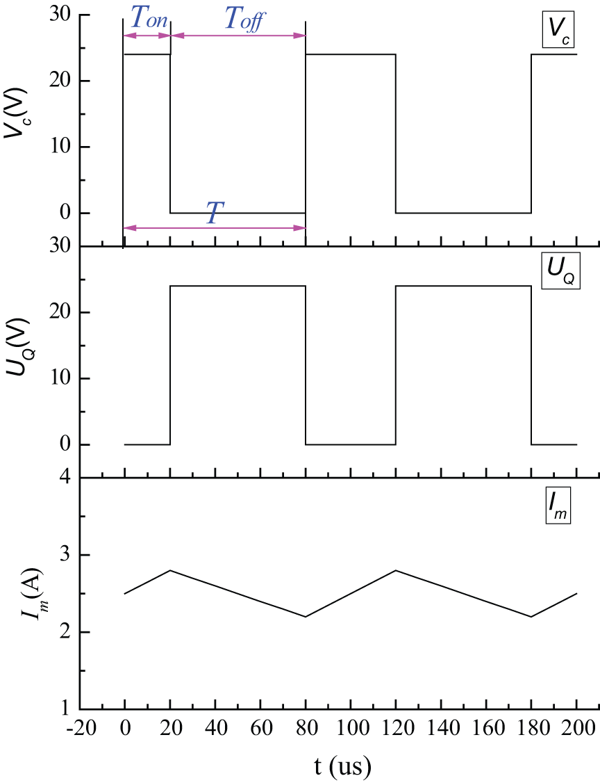
Waveform diagram for the switch regulator circuit.
As shown in Figure 7, the duty cycle is defined as

where
The response of the drive circuit can be described by the following transfer function
where
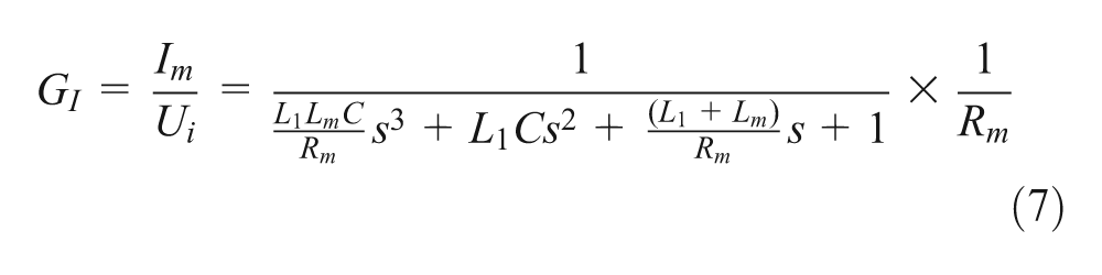
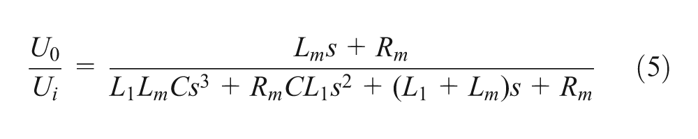
The input voltage
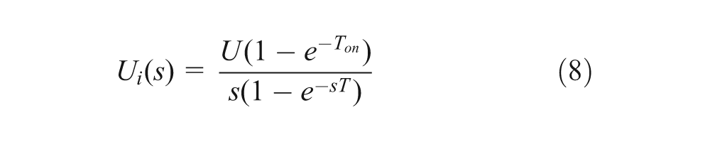
where
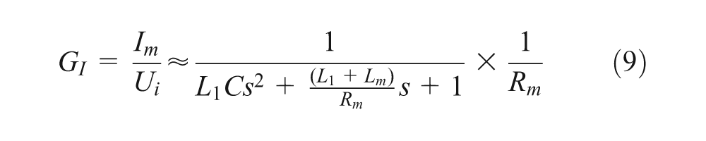
Since the coefficient of s 3 is small enough to be neglected, it can be simplified as
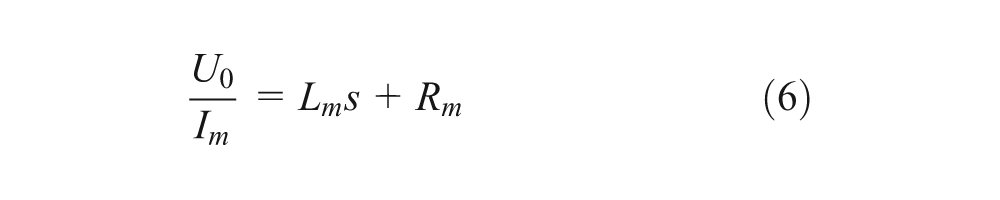
Then, the Laplace transformation of the output current in the electromagnetic coil of MR damper can be expressed as
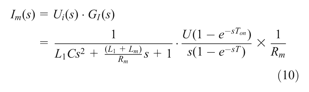
According to the final value theorem of Laplace, the stable value of
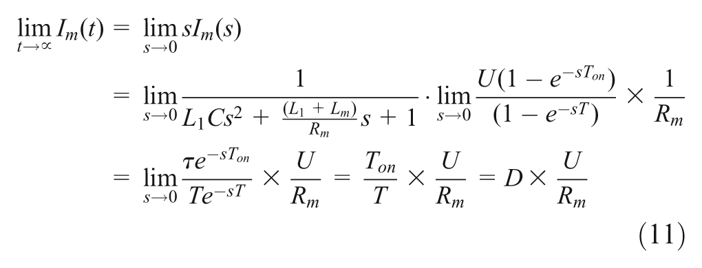
The above analysis indicates that when the current drive circuit approaches a stable state, the current
When a current controller is added in series with electromagnetic coils, the corresponding electromagnetic circuit can be simplified as a second-order linear system with the PWM signal (
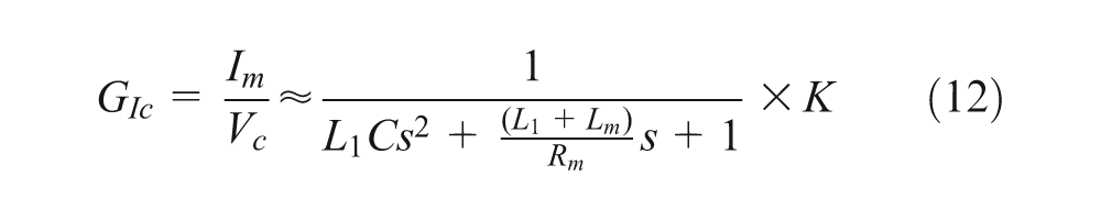
where
The model of equation (12) is used to design a simulation model, and the simulation results are compared with the experimental data in the subsequent sections. The transfer functions are obtained by a parameter identification technique to the second-order model of current responses.
Experimental results and analysis
Figure 8 illustrates the design concept of the long-stroke MR damper used in this study, and Table 1 shows the critical parameters of the damper including the number of the coils
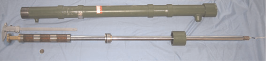
Long-stroke MR damper.
MR damper design parameters.
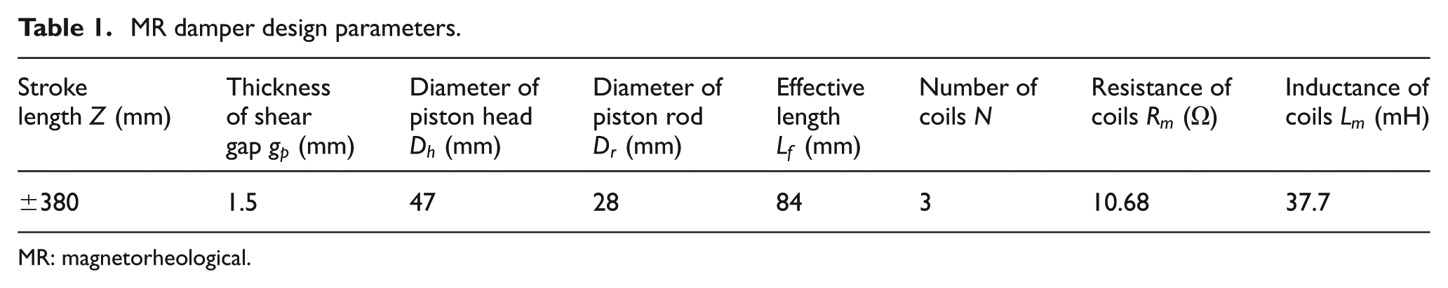
MR: magnetorheological.
Response analysis of electromagnetic drive circuit
This part of the study evaluates the time delay of an electromagnetic drive circuit with four different PWM signals. The experiment was carried out by measuring the voltage
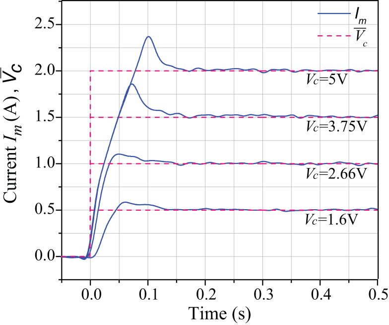
Response of coil current.
The current response time exhibits an approximated increase when the PWM signal
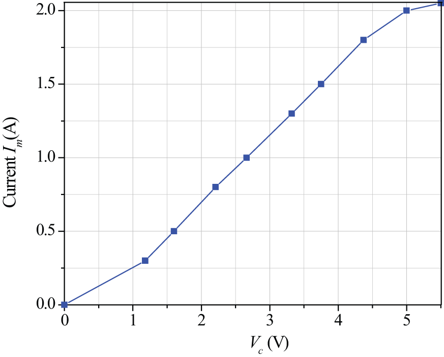
Current versus input voltage.
Response analysis of impact MR buffer system
To further evaluate the time delay of the MR buffer system, a series of tests were conducted under different PWM signals
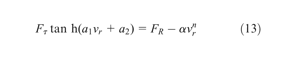
where
Table 2 shows a relationship between the Coulomb force (
Relationship between
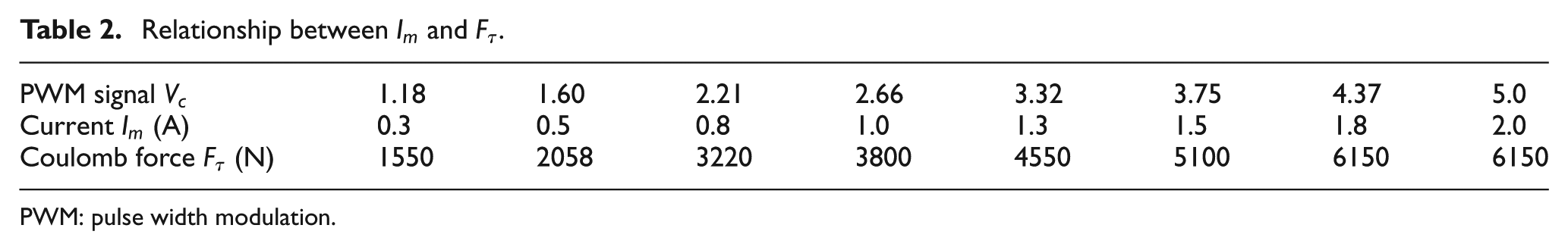
PWM: pulse width modulation.
In order to compare the response between the Coulomb damping force (
Response of MR buffer system: (a) Vc = 1.6 V, (b) Vc = 2.66 V, (c) Vc = 3.75 V, and (d) Vc = 5 V.
As shown in Figure 11, the response of Coulomb force (

When the PWM signal
Time delay of MR buffer system.
The above results indicate that the response time of the MR buffer system to step PWM control signals is the summation of those coming from electromagnet circuit, magnetic hysteresis (BH), MR effect, etc. The electromagnetic circuit can be simplified to a linear second-order system response and the hysteresis and MR effect can be regarded as simple delays. Besides, compared with other factors, the response of electromagnetic circuit has the most significant influence on the response time of the entire MR buffer system.
Proposed time delay compensation methods
Advanced correcting circuit
In order to reduce the time delay in the electromagnetic circuit, this study proposes an advanced circuit for the MR damper. A new equation can be obtained by Laplace transformation of equation (3)
It is noted that the electromagnetic model of an MR damper can be simplified as the transfer function of a first-order inertial system and the current regarded as step signal. Therefore, it is possible to modify the transfer function of electromagnetic circuit model by incorporating an advanced correcting transfer function.
Figure 13 shows the advanced correcting circuit with input
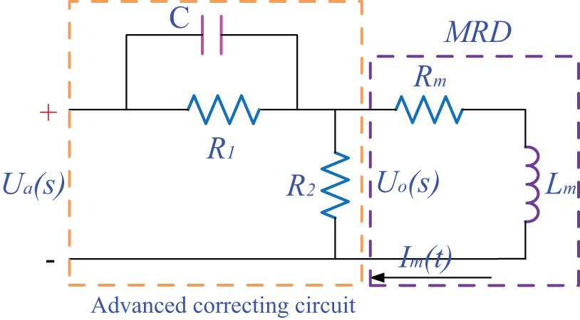
Advanced correcting circuit diagram.
where the coefficients
To figure out the parameters involved in the transfer function and validate the response model of an MR damper under a constant voltage, a testing experiment was setup as shown in Figure 14. During testing, an external resistance was connected in series in order to monitor the changes in the current by measuring the voltage signal at the ends for the wire. A hall probe was positioned at the magnetic pole to measure the magnetic field intensity by a Gaussmeter (450 Lake Shore), which was connected to an oscilloscope.
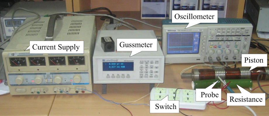
Experimental test.
Since the time delay is unrelated with the values of the input voltage, the response of the magnetic field and the current is compared by normalizing their magnitudes to 1. As shown in Figure 15, the time delay of the magnetic field is much longer than that of the current due to the eddy current effects. Based on the experimental data, the responses of the current and the magnetic field were fitted into two first-order inertial transfer functions,
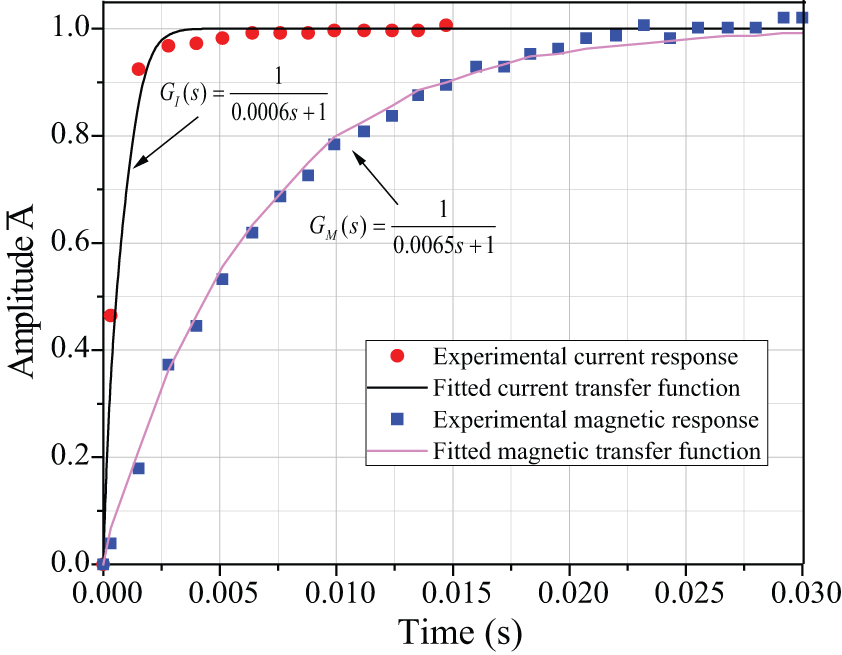
Current and magnetic field response.
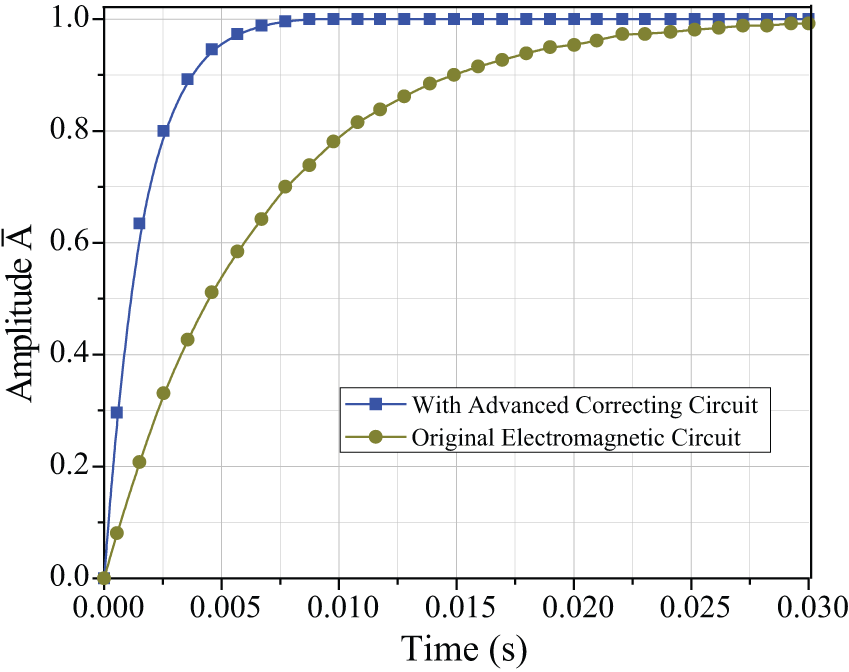
Magnetic field response time.
DSP PID controller
The transfer function of equation (12) can be obtained by a parameter identification technique on the second-order model based on the experimental data of the current response. Figure 17 shows the comparison of parameterized second-order models
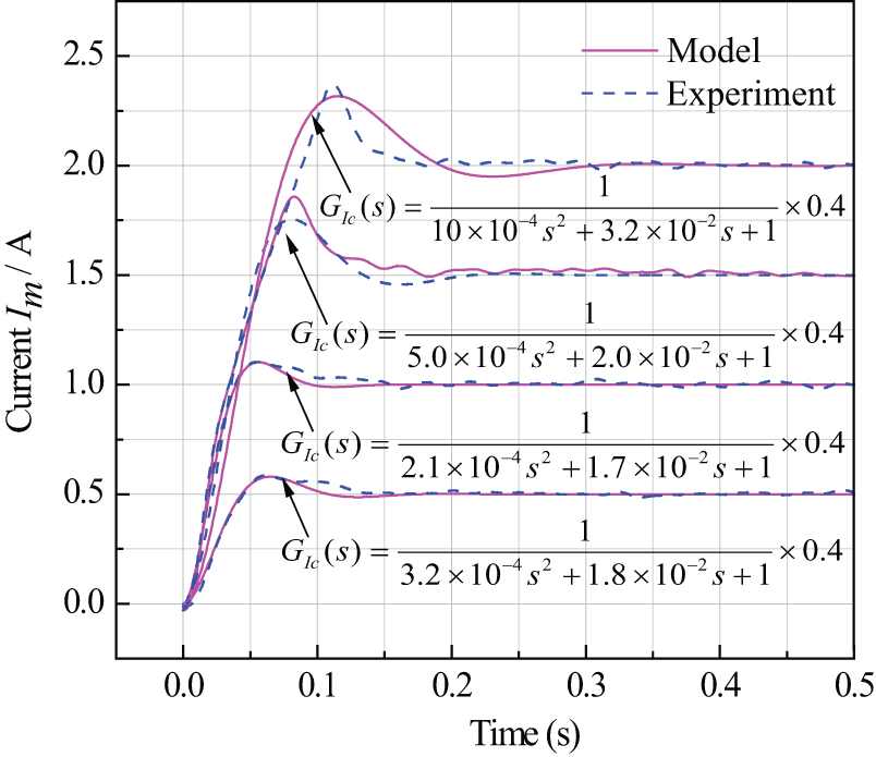
Comparison of second-order model and experimental results.
A PID controller was designed to adjust the delayed response using the DSP controller. The typical PID equation can be written in Laplace transform form
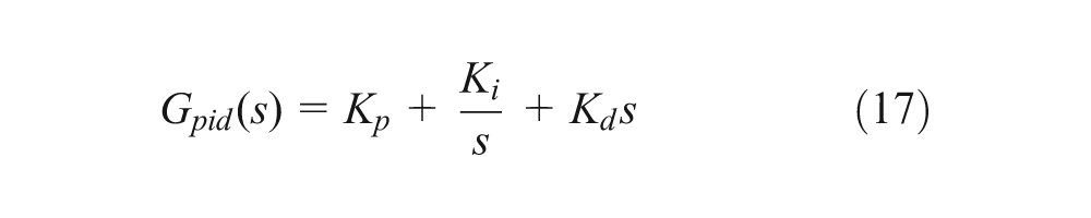
In order to reduce the overall time delay, the transfer function model
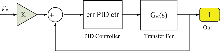
Block diagram of PID controller.
The results show that the step response of the coil current after the PID regulation is greatly improved as compared with original system (Figure 19). It is obvious that the current response (
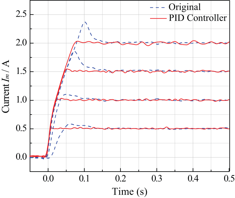
Effect of PID controller.
Conclusion
In this article, a comprehensive research on the time delay of an impact buffer system based on an MR damper was investigated. It is found that the total time delay of the impact buffer system is contributed by the electromagnetic circuit delay, the hysteresis delay (B vs H), and the MR fluid’s response time. It is also found that the time delay is highly dependent on the effectiveness of the electric part of the control hardware. Rheology characteristics of MR fluids seem to play a negligible role in the time delay of impact buffer systems, thus the focus should be placed on the analysis of the electronic parts for such systems.
An MR damper’s electromagnetic circuit can be regarded as a first-order inertial system, whose transfer function can be changed to reduce the time delay. Thus, an advanced correcting circuit was designed and augmented to the first-order circuit model of an MR damper. The simulation results show that the correcting circuit is effective in reducing the response time of magnetic fields. For the electromagnetic drive circuit of the MR buffer system, it can be regarded as a second-order linear system with PWM signals as the input. The experimental results show that the response of the electromagnetic circuit has the most significant influence on the whole MR buffer system. The results also showed that a PID controller is an effective compensation method of the time delay problem of MR systems under impact loadings.
Footnotes
Declaration of conflicting interests
The authors declared no potential conflicts of interest with respect to the research, authorship, and/or publication of this article.
Funding
This work was supported by a Natural Science Foundation of China (NSFC) grant funded by the Chinese Government (nos 51175265 and 51305207).