
Abstract
In order to achieve large displacement output of piezoelectric actuators, piezoelectric stack actuators are realized by mechanically layering or stacking multi-chip piezoelectric wafers in series and electronically connecting electrodes in parallel. Experimental investigations show that different layering or stacking processes greatly affect the dynamic performances of piezoelectric stack actuators. We consider that a linear force and a hysteretic force will be generated by all piezoelectric wafers under the applied voltage to a piezoelectric stack actuator, and the total force will result in the forced vibration of the system consisted of multi-chip piezoelectric wafers and bonding layers. Based on the above-mentioned opinion, an electromechanical model is put forward using a Bouc–Wen hysteresis operator to model the hysteretic force and the transfer matrix method for multibody system to establish the dynamic equation of the piezoelectric stack actuator. This research shows that (1) the layering or stacking processes do not affect the hysteretic characteristics of piezoelectric stack actuators and (2) the layering or stacking processes change the dynamic performance of piezoelectric stack actuators by changing the parameters of the bonding layers. These two conclusions are consistent with the experimental results.
Keywords
Introduction
Piezoelectric actuators based on the inverse piezoelectric effect have been widely used in precision engineering (Devasia et al., 2007; Dong et al., 2009), due to their small size, high energy density, high positioning accuracy, high resolution, and quick frequency response. However, the displacement output of a single-wafer piezoelectric actuator is relatively small, so that piezoelectric stack actuators (PSAs), which are realized by mechanically layering or stacking hundreds of piezoelectric wafers in series and electronically connecting electrodes in parallel, are the best alternative to increase the displacement output with high resolution and positioning accuracy. The layering or stacking processes of multi-chip piezoelectric wafers can be categorized as three types: gluing piezoelectric wafers and electrodes, sintering piezoelectric wafers and electrodes layer by layer, and direct sintering piezoelectric wafers and electrodes as a whole (the co-fired technology).
In order to explain the influence of layering or stacking processes on the properties of PSAs and provide reference for designing PSAs with high performance, it is very meaningful to model the hysteretic and dynamic characteristics of PSAs accurately.
However, the current literatures indicate that the existing researches are mainly focused on hysteresis models, such as the Preisach model (Song et al., 2005; Wolf et al., 2012), the Prandtl–Ishlinskii model (Tan et al., 2009; Tian et al., 2012), the polynomial model (Chonan et al., 1996; Sun et al., 2004), the neural network model (Lien et al., 2010; Zhang et al., 2010), the Maxwell model (Goldfarb and Celanovic, 1997; Lee and Royston, 2000), the Duhem model (Kamlah and Jiang, 1999), the LuGre model (Huang and Chiu, 2009; Li et al., 2009), the differential model (Yau and Yan, 2007), and the Bouc–Wen model (Wang et al., 2011; Wang and Zhu, 2011). These hysteresis models for PSAs can only simulate the hysteretic characteristics of PSAs. When simulating the dynamic characteristics of a PSA, the PSA is generally considered as a single-degree-of-freedom (DOF) system consisted of the equivalent mass, damping, and stiffness of the PSA (Adriaens et al., 2000; Huang and Chiu, 2009; Li et al., 2009; Quant et al., 2009), which has some problems that need to be improved, for instance, first, in a Bode plot, such a system only shows one peak, while experimental results in Croft et al. (1998) indicate that there are many more peaks and valleys in between every two peaks. But in the model in Croft et al. (1998), only two peaks and one valley are taken into account. In fact, there are infinitely many peaks and valleys because the PSA is a distributed parameter system; second, due to ignoring the bonding layers, this method cannot reflect the property differences of PSAs with different layering or stacking processes. However, if considering the bonding layers, high order of the dynamic equation will make the dynamic calculations not enough quick to achieve the dynamic analysis and control.
In order to solve these above problems, we introduce a new dynamic method named transfer matrix method for multibody system (MSTMM). Transfer MSTMM is a new method of multibody system dynamics (MSD) developed by Rui et al. (2008, 2009). The highlights of this method are as follows: study MSD without global dynamic equations of the system, keep low order of the system matrix, and avoid the difficulties in computation caused by high-order matrices. It has been proved by lots of theories and experiments that MSTMM is effective for linear time-invariant multibody systems, nonlinear time-variant multibody systems, multi-rigid-body systems, and multi-rigid-flexible-body systems. Nowadays, MSTMM has been widely applied to lots of engineering cases for features such as without the global dynamic equations of the system, low order of involved system matrices, fast computational speed, and high automation in programming.
In this article, an electromechanical model for PSAs will be put forward and experimentally verified. In section “Hysteretic and dynamic characteristics of PSAs fabricated by different layering or stacking processes,” the dynamic and hysteretic characteristics of three PSAs fabricated by different layering or stacking processes are experimentally tested and analyzed. In section “Electromechanical model,” consider that a linear force and a hysteresis force will be generated by piezoelectric wafers under the applied voltage to a PSA, and the total force will result in the forced vibration of the PSA, and an electromechanical model consisted of an electric model and a mechanical model is presented. In section “Electric model,” the electric model is put forward using a linear function and an asymmetrical Bouc–Wen hysteresis operator to model the linear force and the hysteresis force, respectively. In section “Mechanical model,” the mechanical model which describes the vibration characteristics of the PSA is derived and analyzed by MSTMM. In section “Simplified mechanical model,” two simplified mechanical models are verified and discussed. Finally, in section “Conclusion,” some conclusions are drawn.
Hysteretic and dynamic characteristics of PSAs fabricated by different layering or stacking processes
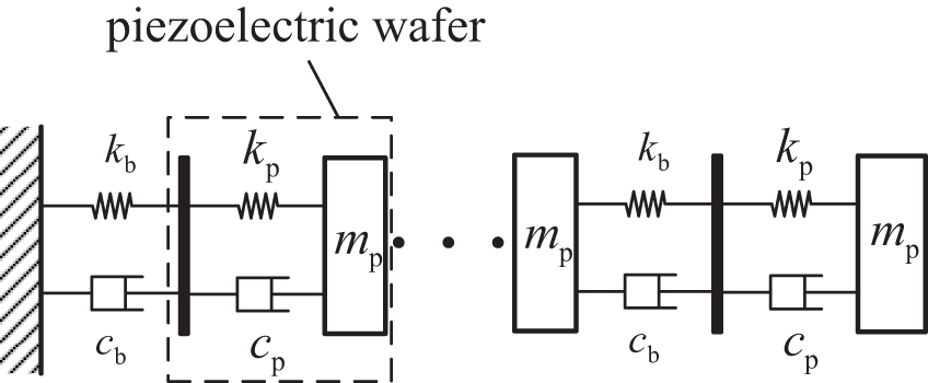
Three PSAs fabricated by different layering or stacking processes are tested by the established experimental setup. Figure 1(a) to (c) shows the photographs of the PSAs fabricated by gluing piezoelectric wafers and electrodes (type: PTBS200, size: 5 × 5 × 18 mm, piezoelectric wafers: 180 chips, applied voltage: 0–200 V, output displacement: 0–18 μm; Kunsan GmbH, China), sintering piezoelectric wafers and electrodes layer by layer (type: WYDS0808020, size: 5 × 5 × 18 mm, piezoelectric wafers: 180 chips, applied voltage: 0–200 V, output displacement: 0–18 μm; China Electronic Technology Group Corporation 26th Research Institute, China), and directly sintering piezoelectric wafers and electrodes as a whole using the co-fired technology (type: P885.51, size: 5 × 5 × 18 mm, piezoelectric wafers: 180 chips, applied voltage: 0–120 V, output displacement: 0–18 μm; the Physik Instrumente GmbH, Germany). Figure 2 shows the schematic representation of PSAs. Observing Figure 2, a PSA is composed of piezoelectric wafers, electrodes, and bonding layers; the multi-chip piezoelectric wafers are mechanically layered or stacked by the bonding layers in series, and the electrodes are electronically connected in parallel.
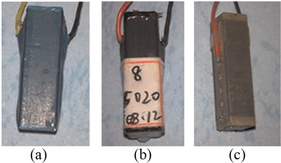
Photographs of the PSAs fabricated by (a) gluing piezoelectric wafers and electrodes (type: PTBS200), (b) sintering piezoelectric wafers and electrodes layer by layer (type: WYDS0808020), and (c) directly sintering piezoelectric wafers and electrodes as a whole (the co-fired technology) (type: P885.51).
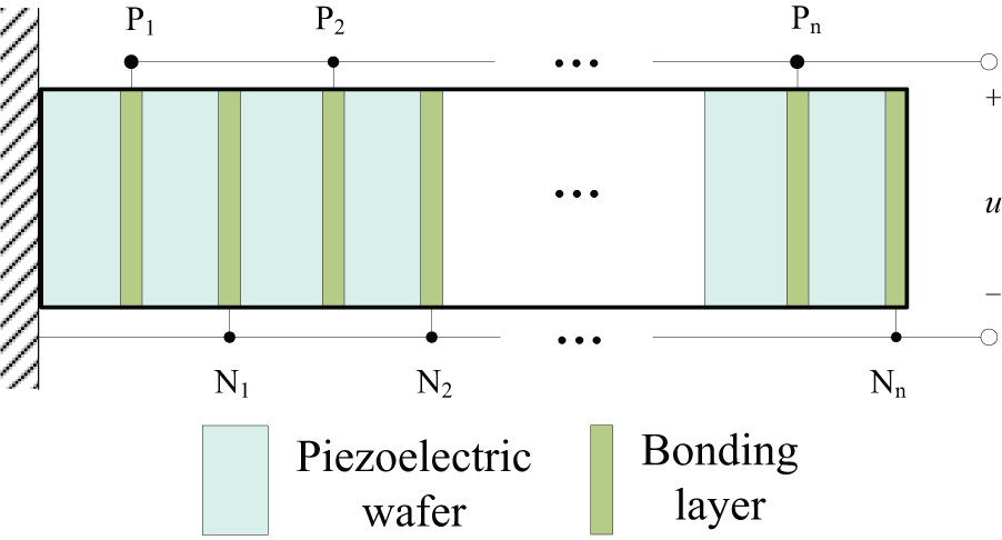
Schematic representation of PSAs.
The running frequency of PSAs is restricted by the heat dissipation, the production process, and the equivalent capacitive load to some extent. So, the step responses of PSAs are used to evaluate the dynamic performance of PSAs. The measured hysteretic curves and unit step responses of three PSAs, as shown in Figure 1, are shown in Figures 3 and 4, respectively. The unit step responses of the PSAs in this article have been normalized to compare with each other by the normalized formula expressed as
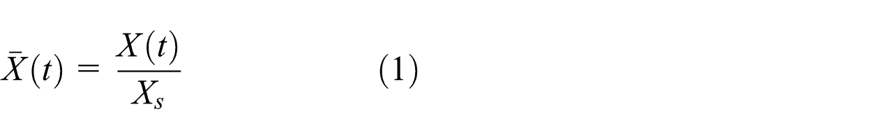
where
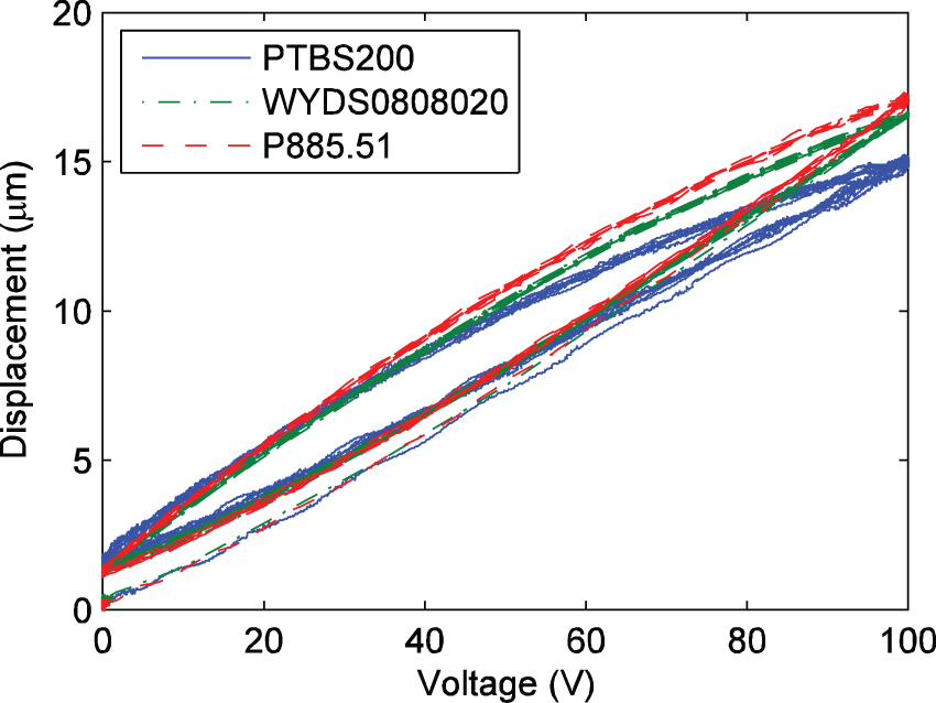
Hysteretic curves of the PSAs fabricated by different layering or stacking processes.
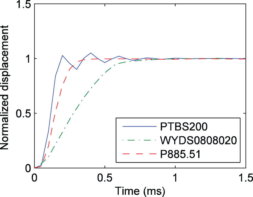
Normalized unit step responses of the PSAs fabricated by different layering or stacking processes.
Observing Figure 3, the hysteresis characteristics of the three PSAs are similar. However, from Figure 4, the step responses of the three PSAs are apparently different. The PTBS200 is an under-damping system, which maybe possesses the shortest life time due to the overshot of the under-damping system. But both the WYDS0808020 and the P885.51 are over-damping systems, and the P885.51 possesses the shortest settling time due to the over-damping systems with appropriate damping. Therefore, the layering or stacking processes do not affect the hysteresis characteristics but affect the dynamic behaviors. Keeping these in mind, we will attempt to reveal the internal mechanism and then put forward some methods to improve the dynamic behaviors of PSAs.
Electromechanical model
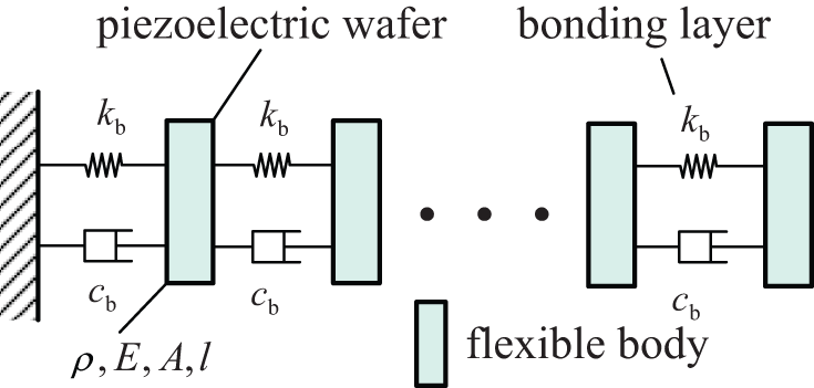
Consider that a linear force and a hysteresis force will be generated by piezoelectric wafers under the applied voltage to a PSA, which consists of N-chip piezoelectric wafers and bonding layers, and then the total force will result in the forced vibration of the piezoelectric wafers and the bonding layers. On this basis, the electromechanical model is shown in Figure 5 and can be expressed as
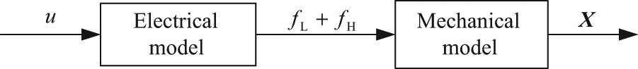
Block diagram of the electromechanical model for PSAs.
where
Electric model
In this section, we investigate the electric model, which is a part of the electromechanical model. The electric model is composed of the linear and hysteretic functions. The linear function models the linear force and can be expressed as
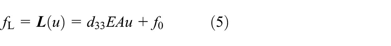
where d
33 is referred to as the piezoelectric “strain” constant, E is the equivalent piezoelectric stiffness, u is the voltage input, and f
0 is the initial force. In the zero initial condition,
The hysteretic function of electric model simulates the hysteretic force generated by PSAs under the applied voltage. The Bouc–Wen hysteresis operator simulates the hysteresis loop using a nonlinear differential equation with uncertain parameters and can match a wide class of hysteretic systems by choosing the appropriate parameters (Wen, 1976). In recent years, The Bouc–Wen model for PSAs was put forward using the Bouc–Wen hysteresis operator to simulate hysteretic characteristics of PSAs (Wang et al., 2011; Wang and Zhu, 2011). Utilizing an asymmetrical Bouc–Wen hysteresis operator to simulate the hysteretic force yields the electric model as
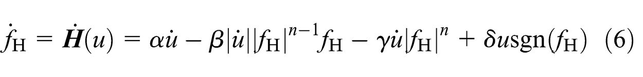
where
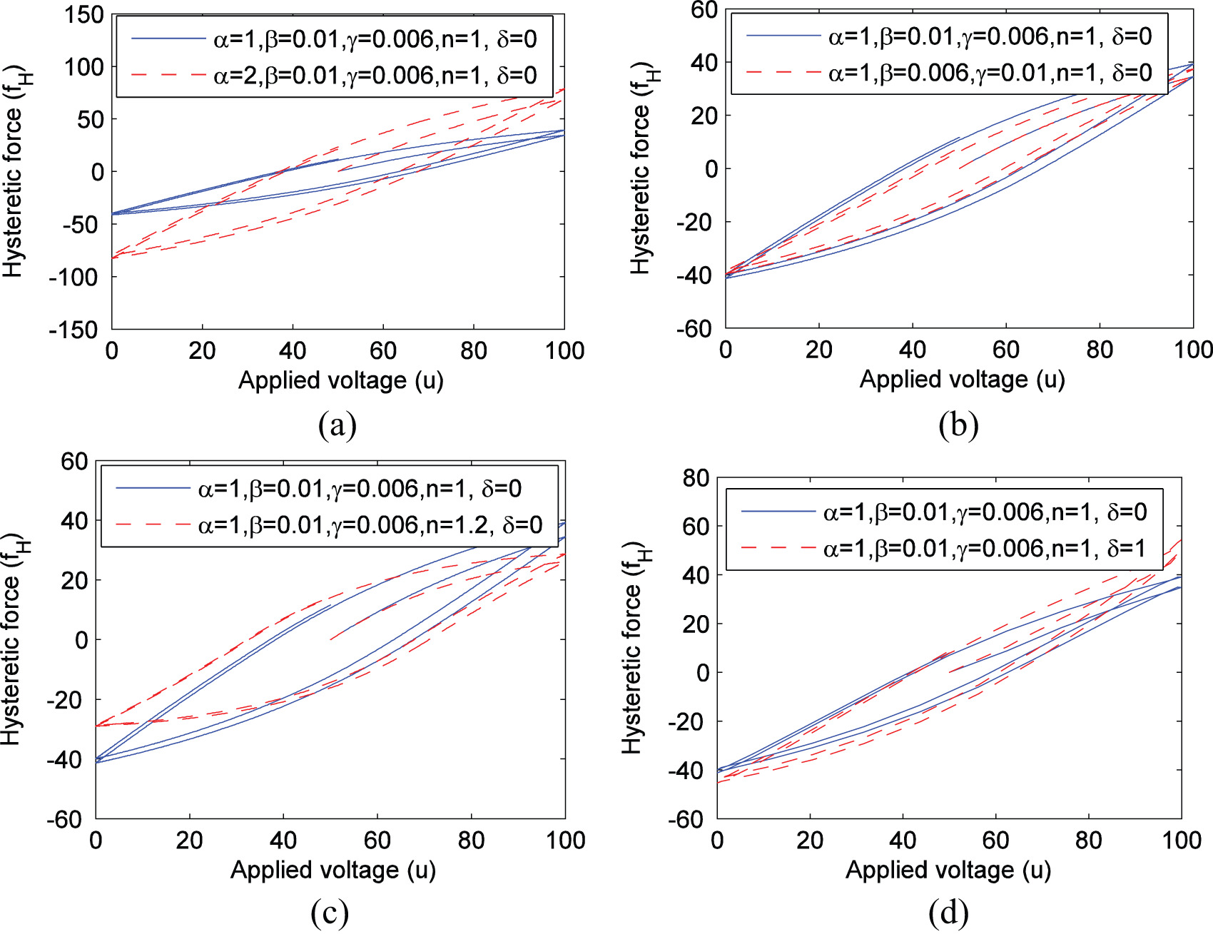
Influence of the model parameters on the hysteretic loops: (a)
The hysteresis is a unique input–output characteristic of the piezoelectric material. However, the bonding layers are not involved in the process. The above phenomenon is described by the electric model given by equations (5) and (6). Therefore, we consider that the bonding layers do not affect the hysteresis characteristic of PSAs, which is consistent with experimental results presented in section “Hysteretic and dynamic characteristics of PSAs fabricated by different layering or stacking processes.”
Mechanical model
In this section, we consider a mechanical model, which is a part of the electromechanical model.
Free and undamped vibration
State vectors
The state vectors of the connection point among any bodies and hinges vibrating are defined as
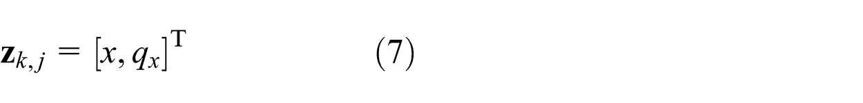
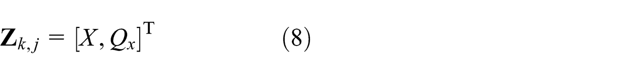
where X and Q x are corresponding modal coordinates of physics coordinates of displacement x and internal forces q x, respectively, and subscripts k and j are the body indices and the hinge indices, respectively. For natural vibrations of a linear multibody system, the physics coordinates of displacement and interior force can be assumed as
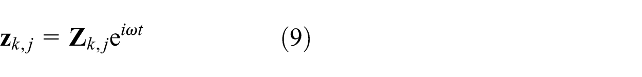
where
Transfer matrix of a piezoelectric wafer
As a first step, we consider the dynamic model of a piezoelectric wafer as a flexible body which is shown in Figure 7. The piezoelectric wafer has an elasticity modulus E, a mass density
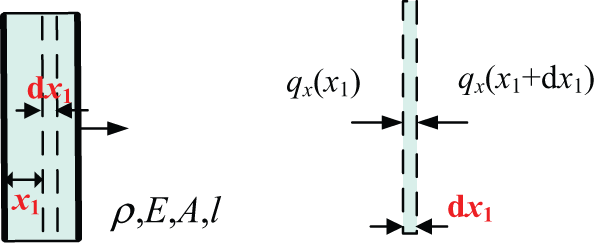
Dynamic model of a piezoelectric wafer.
The impulse balance for the piezo slice can be obtained easily from Figure 7
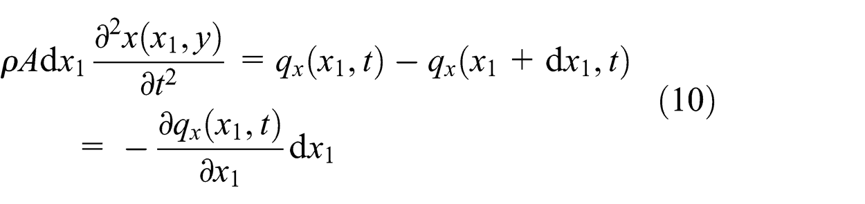
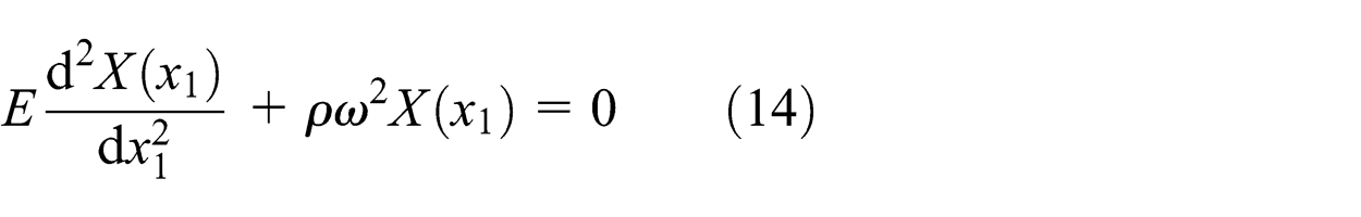
For the free and undamped vibration, the strain
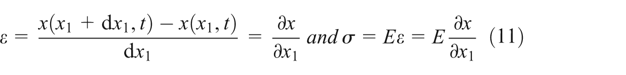
Based on equations (10) and (11), the following relation for the interior force can be derived
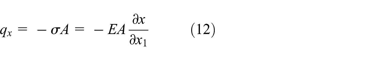
Therefore, the dynamic equation of the piezo slice can be given by
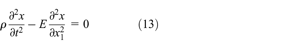
Substituting equation (9) into equation (13), the eigenfunction can be assumed as
The solution to eigenfunction can be simply given by
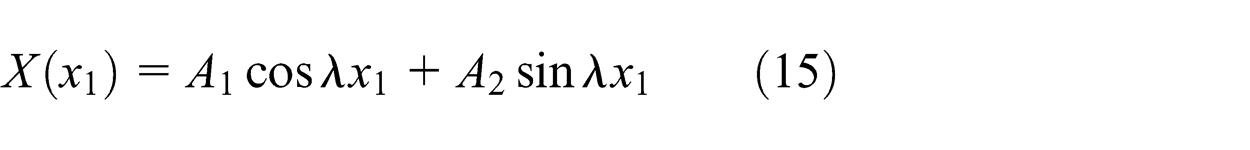
where
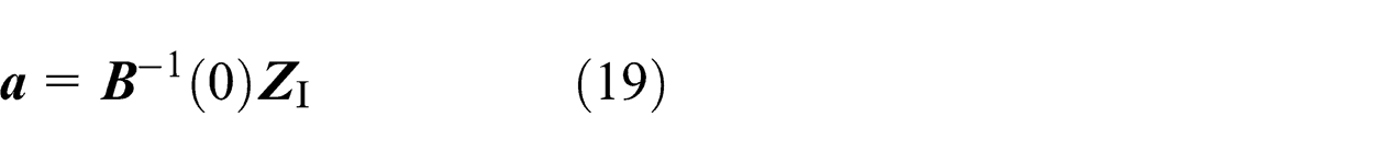
According to equations (12) and (15), we can obtain
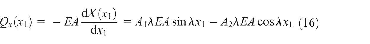
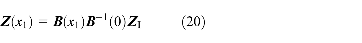
Substituting equation (15) into equation (16), we have

where
Let
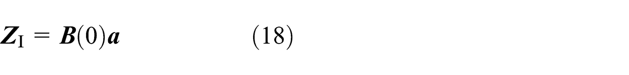
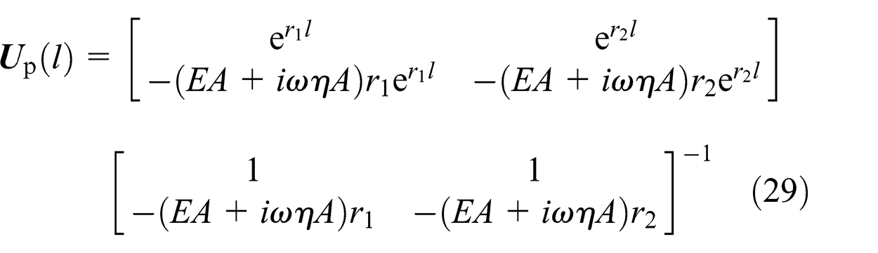
Therefore, the transfer equation of the piezo slice can be expressed as
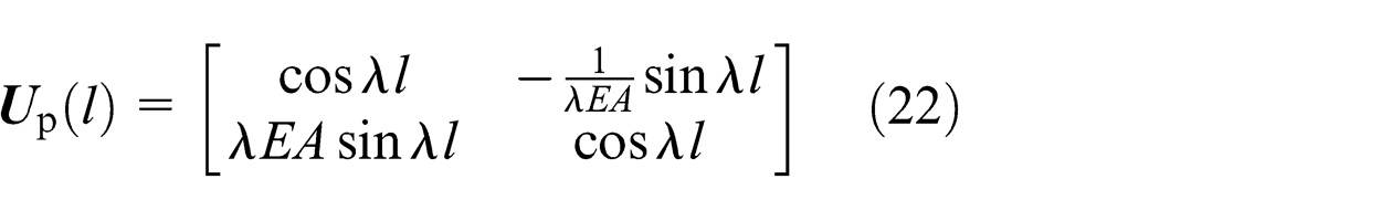
The transfer matrix can be written as
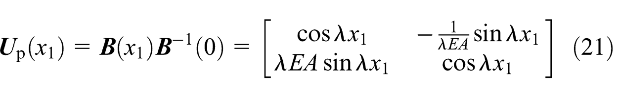
When
Transfer matrix of a bonding layer
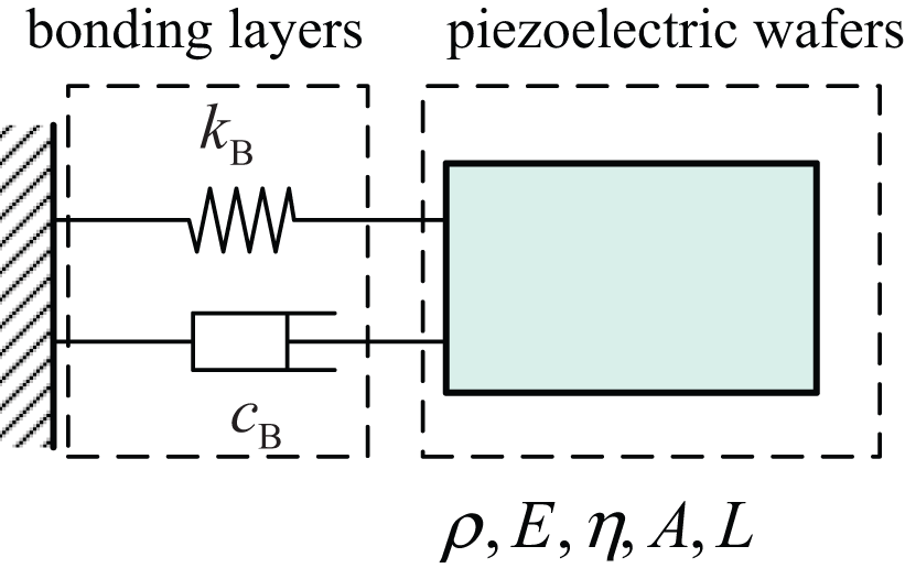
Second, we put forward a transfer matrix to represent the mechanical characteristics of a bonding layer which can be considered as a simple spring–damper system as shown in Figure 8.
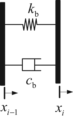
Dynamic model of a bonding layer.
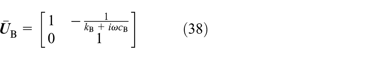
For the free and undamped vibration, the transfer matrix of the bonding layer can be given by
Transfer equation and transfer matrix of a PSA
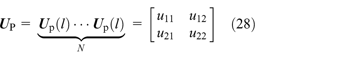
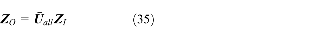
The dynamic model of a PSA consisted of N-chip piezoelectric wafers and bonding layers is shown in Figure 9. The overall system transfer equation and overall transfer matrix, which relate the state vectors at the input and output ends of the PSA, can be assembled and calculated as
The boundary conditions are
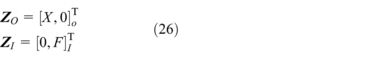
Using boundary conditions of the PSA in the overall transfer equation, we obtain the eigenfrequency equation
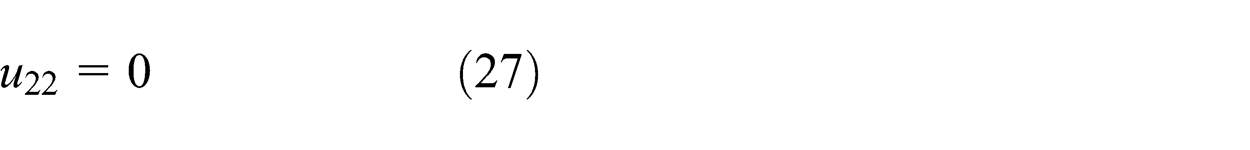
Dynamic model of a PSA.
Solving equation (27), we obtain the eigenfrequencies
Parameters of a PSA (type: P885.51, size: 5 × 5 × 18 mm, input voltage: 0–120 V, output displacement: 0–18 μm; the Physik Instrumente GmbH).
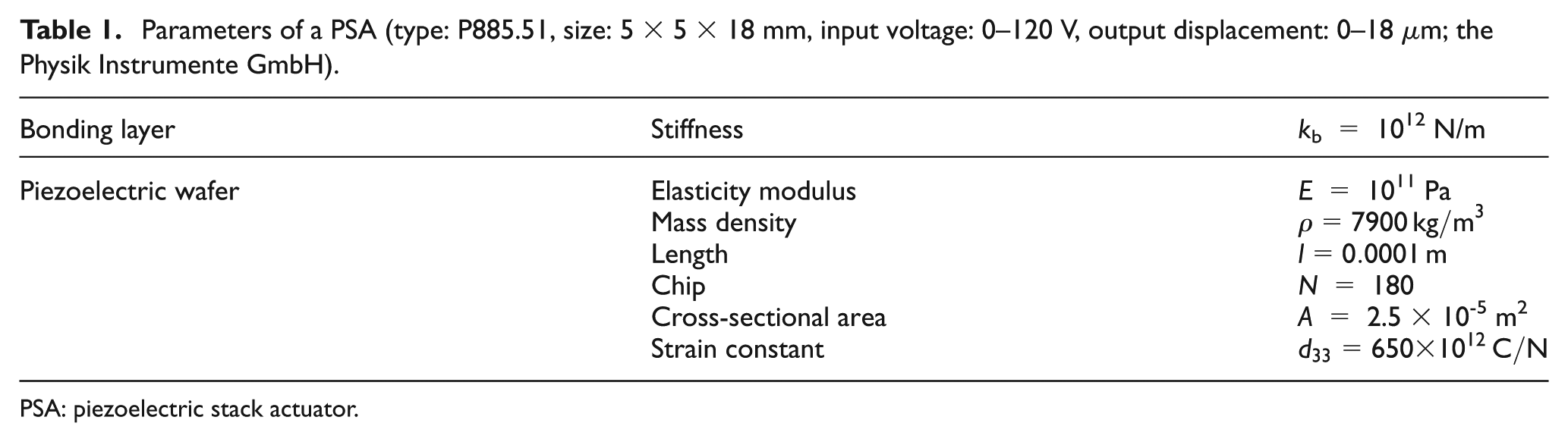
PSA: piezoelectric stack actuator.
If the bonding layers are ignored, the transfer matrix of the PSA can be rewritten as
The first five natural frequencies of a PSA, whose bonding layers are ignored, are also listed in Table 2, which indicates that the existence of bonding layers changes the natural frequencies of the PSA. That is to say, bonding layers can affect the dynamic behaviors of the PSA.
First five natural frequencies of the PSA (rad/s).
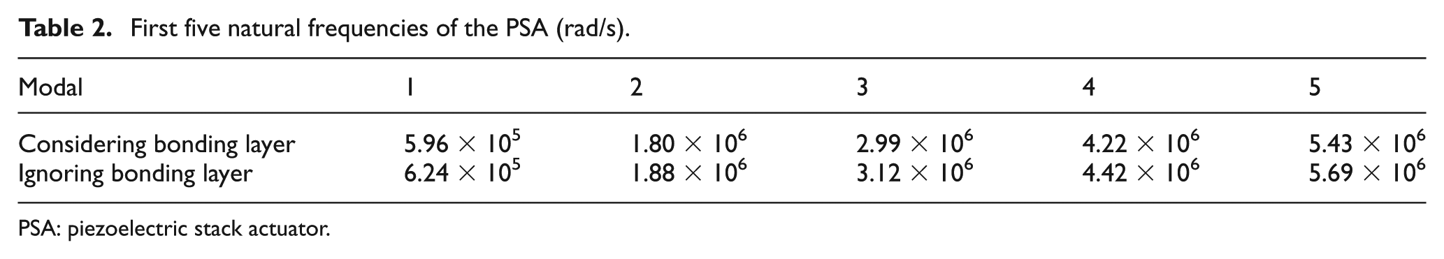
PSA: piezoelectric stack actuator.
A set of numerical simulations are carried out to assess the effects of the stiffness of bonding layers on the natural frequencies and eigenfunctions of system. The first five natural frequencies versus different values of stiffness k b are plotted in Figure 10. From Figure 10, as the stiffness of the spring increases, the natural frequencies increase exponentially but eventually converge to particular values. This is because of the fact that piezoelectric wafers with a hard spring at the boundary behave similar to that of a clamped–clamped one. Hence, further increase in the spring stiffness will not affect the natural frequencies much.
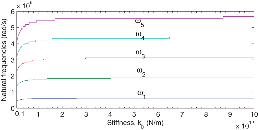
First five natural frequencies of the PSA versus different values of the stiffness k b.
In general, we hope that the first several natural frequencies of a PSA are higher, which means that the PSA possesses the faster response speed, stronger load capacity, and higher bandwidth. Therefore, in order to ensure the dynamic performance of the PSA listed in Table 1, as an example, we should try to make the stiffness of a bonding layer greater than 1012 N/m.
Forced and damped vibration
For the damped vibration, the complex transfer matrix of the piezoelectric wafer shown in Figure 7 can be rewritten as
where
The complex transfer matrix of the bonding layer shown in Figure 8 can be rewritten as
Then, the overall complex system transfer equation and overall transfer matrix can be calculated as
Substituting boundary conditions given by equation (26) into equation (32), we have
where
A numerical simulation is carried out to assess the effects of the stiffness and damping of the bonding layer on the amplitude–frequency and phase–frequency characteristics of system. The Bode diagrams of the PSA, versus considering and ignoring bonding layers, respectively, are plotted in Figure 11, which indicates that bonding layers can affect the dynamic responses of the PSA. Figure 12(a) and (b) shows the Bode diagrams versus different values of stiffness k
b and damping c
b, respectively. The other parameters of the PSA used for this simulation are listed in Table 1. From Figure 12(a), the stiffness of the bonding layer can change the low-frequency response of the PSA. As it can be observed in Figure 12(b), the damping can influence the high-frequency response. If the damping is small enough, as shown by the curve (
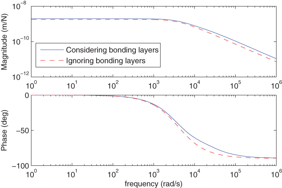
Bode diagrams of the PSA with considering and ignoring bonding layers.
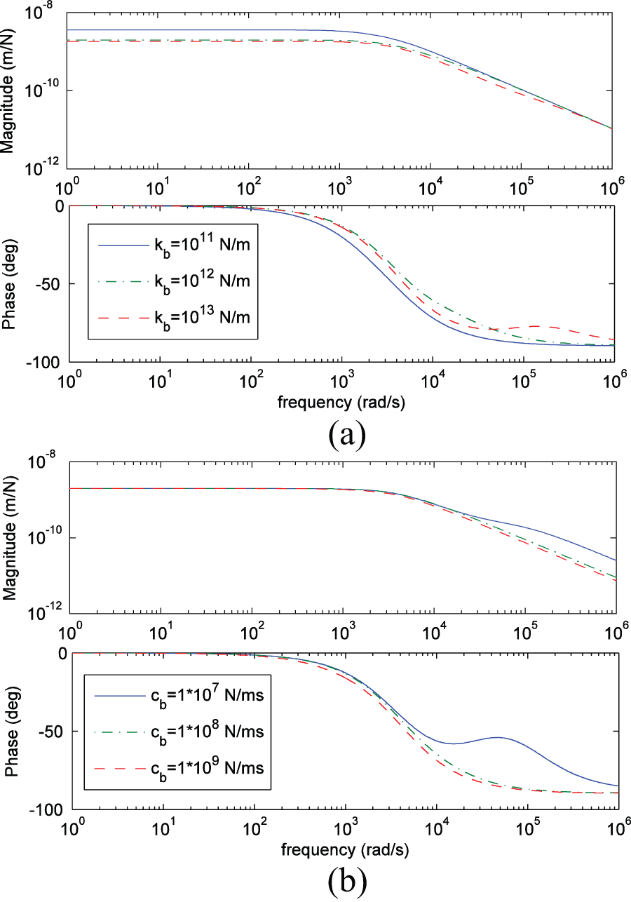
Bode diagrams of the PSA versus different values of the (a) stiffness and (b) damping of a bonding layer.
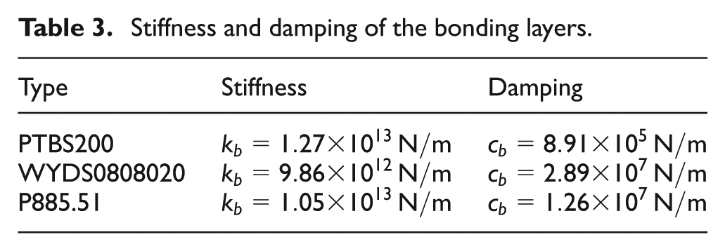
The stiffness and damping of the bonding layers obtained by the parameter identification method proposed by Tian et al. (2012) are listed in Table 3. The step responses predicted by this method and measured by experiment are shown in Figure 13, which indicates that this method can match the experimental result of these three PSAs well.
Stiffness and damping of the bonding layers.
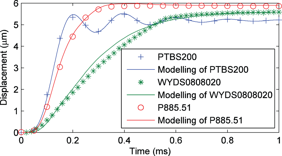
Step responses of the three PSAs by this method and measured by experiment measured and predicted.
According to the above analyses, it is reasonable to believe that this method considering bonding layers can explain the influence of layering or stacking processes on the properties of PSAs, provide reference for designing PSAs with high performance, and achieve a higher accuracy than ignoring bonding layers.
Simplified mechanical model
The mechanical model proposed in section “Mechanical model” can be used for design and implementation of a PSA. However, to achieve real-time control of a PSA, we may hope two simpler models which possess a faster calculation speed and can ensure the modeling accuracy. Therefore, some simplified mechanical models are discussed in this section.
Case 1
Considering a piezoelectric wafer as a mass–spring–damper system, the simplified model 1 is shown in Figure 14. Then, the complex transfer matrix of the piezoelectric wafer can be given by
where
Simplified model 1.
Therefore, the overall complex system transfer equation and overall transfer matrix can be calculated as
The Bode diagrams of this simplified model and the original model proposed in section “Mechanical model” are plotted in Figure 15, which indicates that this simplified model can also represent the dynamic characteristics of the PSA. The simplified model 1 is an approximation of the cutoff modal method where the flexible body (the piezoelectric wafer) is simplified to a single-DOF system. Due to the high natural frequency of single piezoelectric layer, therefore, this simplification has little effect on frequency response curve (0–106 rad/s).
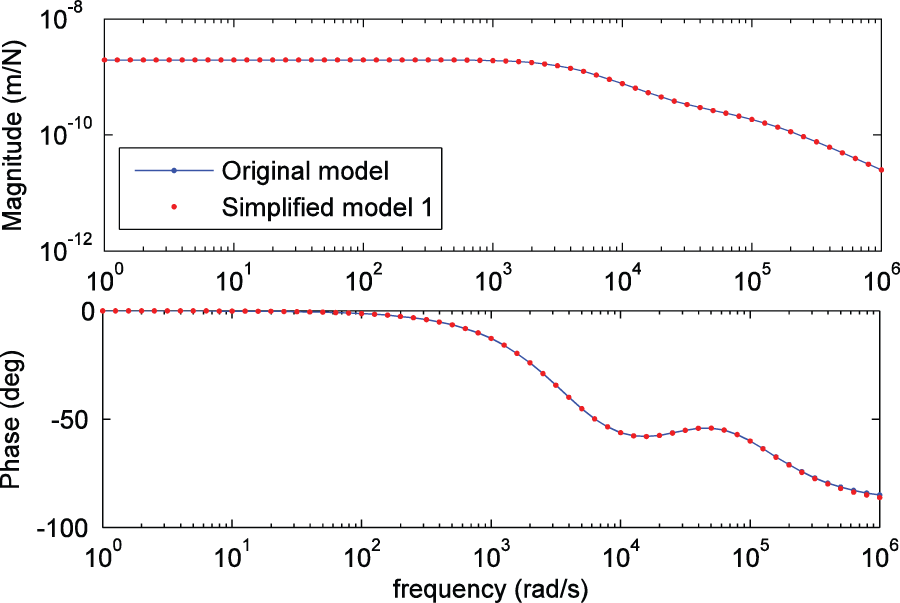
Bode diagrams of the simplified model 1 and the original model proposed in section “Mechanical model.”
Case 2
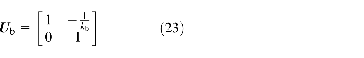
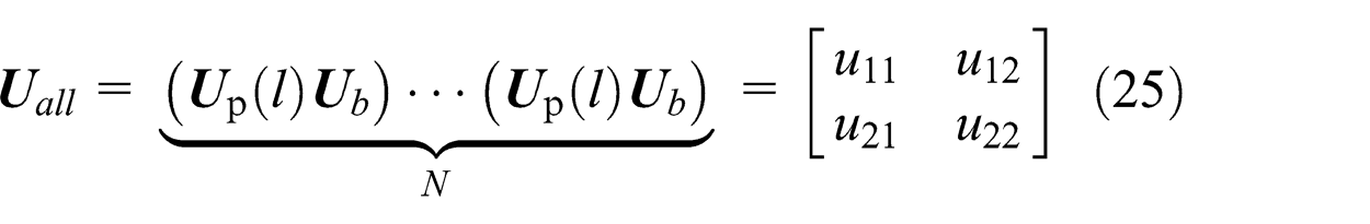
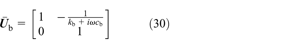
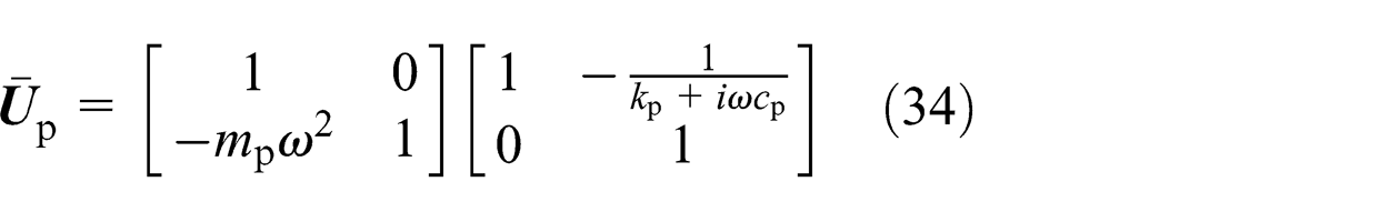
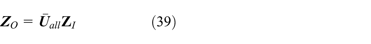
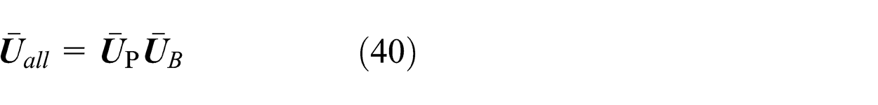
Considering all piezoelectric wafers as one flexible body and all bonding layers as one spring–damper system, the simplified model 2 is shown in Figure 16. From Figure 16, the complex transfer matrix of the all piezoelectric wafers can be given by
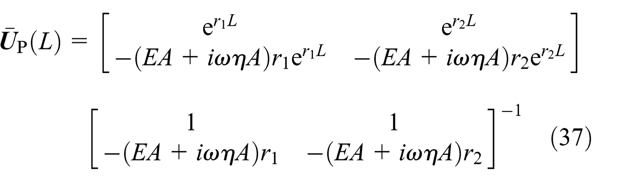
Simplified model 2.
The complex transfer matrix of the all bonding layers can be written as
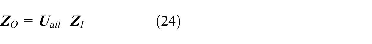
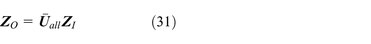
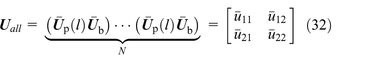
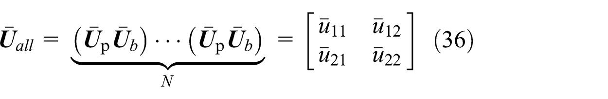
Therefore, the overall complex system transfer equation and overall transfer matrix can be calculated as
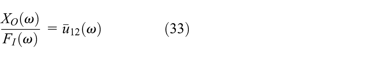
The Bode diagrams of this simplified model and the original model in section “Mechanical model” are plotted in Figure 17, which indicates that the simplified model 2 can also model the dynamic responses of the PSA.
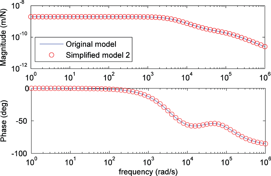
Bode diagrams of the simplified model 2 and the original model proposed in section “Mechanical model.”
Conclusion
In this article, in order to explain the influence of layering or stacking processes on the properties of PSAs and provide reference for designing PSAs with high performance, an electromechanical model was put forward, which considered that a linear force and a hysteretic force generated by all piezoelectric wafers would result in the forced vibration of the system consisted of all piezoelectric wafers and bonding layers. The research showed that the layering or stacking processes changed the dynamic performance of PSAs by changing the parameters of the bonding layers, which was consistent with the experimental results. In addition, in theory, it can be concluded that the dynamic performance of PSAs can be improved by sintering the bonding layers with a properly large damping.
Footnotes
Declaration of Conflicting Interests
The author(s) declared no potential conflicts of interest with respect to the research, authorship, and/or publication of this article.
Funding
The author(s) disclosed receipt of the following financial support for the research, authorship, and/or publication of this article: This work was financially support by National Natural Science Foundation of China (grant no. 61304137).