
Abstract
To improve the multi-functionality of a structure, a foldable or deployable structure with variable stiffness is needed. This article presents dual-stiffness structures with two stiffness states: a stiff state and a flexible state for a multi-mission capability. This dual-stiffness structure is based on a hybrid structure that combines rigid and flexible segments; when the rigid segments are rearranged, the bending motion of the compliant material is constrained by the rigid segments, which varies the stiffness of the structure. Instead of continuously changing the stiffness, the dual-stiffness structure abruptly changes the stiffness state with a simple reconfiguring mechanism. We developed two reconfiguring mechanisms: a sliding mechanism and a folding mechanism. Using a layering process, the dual-stiffness structure with a two-dimensional multi-layer design was manufactured. To verify the behavior of the structure, a simplified structure with no sliding mechanism was designed and simulated using a finite element method. The ratio of the length of a rigid segment to the length of a compliant segment determined the stiffness of the structure. This dual-stiffness structure with the reconfiguring mechanism can be effective for applications that require a big change in stiffness, such as for a deployable solar panel, or flexible display.
Keywords
Introduction
The structure of a system generally has a constant stiffness regardless of the operating condition. To improve the usability of the system under various operating conditions, a variable stiffness structure should be considered. When the stiffness of the structure can be actively changed, the performance of the system can be enhanced. This variable stiffness structure can be applied to a flexible fin to increase the thrust of a robotic fish, to a morphing wing to improve the efficiency of an aircraft, and to a deployable structure to increase its functionality. Therefore, a variable stiffness structure can improve the functionality of a system according to the operating conditions.
Variable stiffness has been studied as a mechanism or in relation to the structure itself. The stiffness of a system can be varied using friction, springs, or the nonlinear characteristics of a compliant material. To increase the stiffness of a system using friction, a vacuum pump can be used. The friction between a laminated pack of sheets or between a soft vinyl tube and Styrofoam beads can be increased by creating a vacuum, which increases the bending moment of the system (Kawamura et al., 2002; Mitsuda et al., 2002). The friction-based method can also be used for a jamming mechanism, which is used to vary the stiffness of a structure by controlling the pressure (Cheng et al., 2012; Kim et al., 2013). Most variable stiffness mechanisms that utilize the friction-based method require a vacuum pump to control the pressure.
To more precisely control the variation of the stiffness, springs with a nonlinear force–displacement relationship have been used (Ham et al., 2009; Wolf and Hirzinger, 2008). By controlling the displacement of a spring, the stiffness of a joint can be actively or adaptively changed depending on the operating conditions. A variable stiffness mechanism using a spring-based method has been applied to a swimming platform (Ziegler et al., 2011). The stiffness of each joint was varied by pulling a lever, and the distribution of the stiffness was tested. Similar to the spring-based method, a variable-effective-length spring has been used to vary the stiffness of a caudal fin to maximize its thrust (Kobayashi et al., 2006). The apparent stiffness of the structure was changed by adjusting the length of the rigid plate that supported the plate spring. A dual-stiffness mechanism for a bi-stable in-plane switch with separate dual-stiffness cantilevers and an interlocking mechanism was designed and operated in two different spring constant regimes (Sterner et al., 2007). Generally, these spring-based methods require sufficient space for adjusting the lever or rigid plate.
To apply the stiffness variation to an entire structure such as a morphing wing, changing the material property of the structure has been considered. As the property of the material changes, the entire stiffness of the system can be varied. In general, the stiffness of a structure has been changed using smart material components, which can be used to drive the structural deformation using an electrical, a thermal, a chemical, or a magnetic stimulus (Mcknight et al., 2010). A shape memory alloy, a shape memory polymer, piezoelectric materials, and other materials have been used to vary the stiffness of a structure or deform it based on the operating conditions. The flexural bending stiffness of a multi-layered beam, which comprised a base layer with polymer layers on the upper and lower surfaces, and stiff cover layers, could be varied by changing the property of a polymer layer (Gandhi and Kang, 2007). When the stiffness of the polymer layer increased, the entire multi-layered beam bent as one structure, and its bending stiffness increased. On the other hand, when the shear modulus of the polymer layers was reduced, the overall flexural bending stiffness decreased. The stiffness of the polymer layers was controlled by temperature. Similarly, the stiffness of a structure inspired by a vertebral column was adjusted using a compliant material (Huh et al., 2012). The design of this structure was inspired by a vertebral column, which has rigid segments (bones) and flexible segments (cartilage). When a compressive load is applied to the structure, the stiffness of the compliant segments increases as a result of the nonlinear property of the compliant materials. To alter the stiffness and shape of a structure, a combination of rigid and flexible materials was designed (Vos and Barrett, 2011). The stiffness and shape of a pressure-adaptive honeycomb were changed by adjusting the pressure. Using this pressure-adaptive honeycomb, the aerodynamic characteristics of a wing section were successfully altered. For morphing structures, the use of a variable stiffness material for reconfigurable surfaces and structures has been considered (Mcknight et al., 2010). A lower stiffness for a large deformation was used to limit the energy required for the deformation, whereas a high stiffness was maintained for structural efficiency. Using a shape memory polymer, the reconfigurable surfaces and structures were actively changed by altering the temperature. Therefore, finding an appropriate material property is an important issue.
To improve the functionality of a structure, a foldable, deployable, or morphing structure can be used to provide multi-mission capabilities. These features can be implemented using a variable stiffness structure, which usually requires two states: the flexible state and the stiff state. For example, currently, small satellites have deployable structures that can be extended using an actuator. The size of these deployable structures should be minimized to reduce the volume of the satellite. When a satellite reaches its final destination, the deployable structures should be maximized for proper operation. Even if the stiffness of the structure does not need to vary continually, the variation range should be large enough to distinguish the difference between the flexible state and the stiff state. If a simple and compact system is needed, then a dual-stiffness structure is one good solution. Therefore, a dual-stiffness structure is sufficient for a foldable, deployable, and morphing system, and the number of actuating systems can be reduced by simplifying the structure. These dual-stiffness structures are basically applied to large areas with large deformations. In order to use the previously mentioned variable stiffness structures with the friction-based and spring-based methods for large areas, numerous actuators or large spaces are required. Therefore, a new design concept for a dual-stiffness structure is needed to provide simple and compact variable stiffness structures for a large area, while maintaining a wide stiffness-variation range.
This article presents dual-stiffness structures with a reconfiguring mechanism for the rigid segments. These dual-stiffness structures are designed based on a combination of rigid and flexible materials. The stiffness of the dual-stiffness structure is determined by the arrangement of the rigid segments, which is constrained by the bending motion of the compliant segments. To vary the stiffness of the structure, two reconfiguring mechanisms are considered: a sliding mechanism and a folding mechanism. Using these mechanisms, the stiffness of the structure was varied between two conditions: the stiff state and the flexible state. A hybrid structure with no sliding mechanism was designed and simulated using a finite element method to verify the behavior of the structure. By changing the design parameters, eight different dual-stiffness structures were designed and manufactured using a layering process, which is suitable to use for a two-dimensional multi-layer design. We conducted experiments to measure the stiffness of the structures and to verify their functionality. The results show that the stiffness of the dual-stiffness structure can be varied by reconfiguring the rigid segments, and the functionality of the structure can be improved. These dual-stiffness structures with the reconfiguring mechanism can be applied to various systems such as a morphing wing, deployable solar panel, and flexible display.
Design concept
In this section, we present the concept of dual-stiffness structures that can be applied to a large area. The basic concept of the structure was inspired by an armadillo’s skin, which is a composite material consisting of hard mineralized tiles connected by soft non-mineralized collagen fibrils (Chen et al., 2011). The rigid segments and flexible segments compose a hybrid structure, and the stiffness of this structure can be varied by constraining the movement of the compliant segments using the rigid segments. The configuration of the structure is varied, and its stiffness is changed by rearranging the rigid segments.
Bio-inspired structure design
An armadillo’s skin, which can protect its body from predators, consists of rigid plates (dermal bones) and flexible skin. This skin functions as protective armor, which is called the osteoderm (Chen et al., 2011). It consists of a composite material composed of hard tiles and soft collagen fibrils. The hard tiles, which are hexagonal or triangular in shape, are connected by non-mineralized collagen fibers, called Sharpey’s fibers, which can be used to bend the osteoderm with a variable curvature. Because of the hybrid structure of rigid and flexible materials, some armadillos can roll up into a ball when threatened by a predator, as shown in Figure 1. We derived the basic design principles based on this hybrid structure. Rigid materials and compliant materials are alternated. The design concept was inspired but not directly analogous to the armadillo. The rigid segments play a role in maintaining the shape, whereas the compliant segments create a bend that depends on their stiffness. This structure can be easily configured to provide various designs and sizes because of its simple design parameters. Therefore, the concept of a dual-stiffness structure can be used for a simple and scalable design.
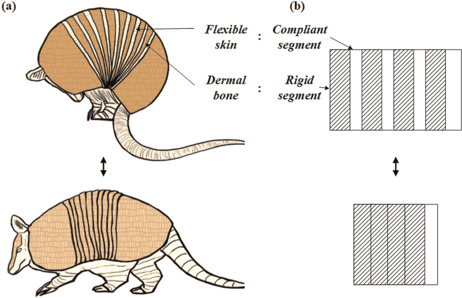
Basic concept of dual-stiffness structure inspired by armadillo’s skin: (a) sketch of armadillo and (b) concept of hybrid structure, which is a combination of rigid and flexible segments.
Mechanism
The stiffness of the structure can be varied by constraining the movement of the compliant segments using the rigid segments. Figures 2 and 3 show the concept of the stiffness-variation method using the dual-stiffness structure. Previous variable stiffness structures varied their stiffness by changing the property of the compliant material. By compressing the compliant material or increasing the friction with a vacuum pump, the stiffness of the structure was varied based on a property of the compliant material. This means that the stiffness of the system was dominated by the compliant segment. However, the stiffness of the dual-stiffness structure is determined by the reconfiguration of the rigid component. The configuration of the structure is varied by rearranging the rigid segments, which provides different stiffness states. To increase the stiffness of the dual-stiffness structure, the bending of the compliant part should be constrained, which is the stiff state of the dual-stiffness structure. Because the reconfiguration of the rigid segments can change the stiffness, the stiffness of the system is dominated by the rigid segments.
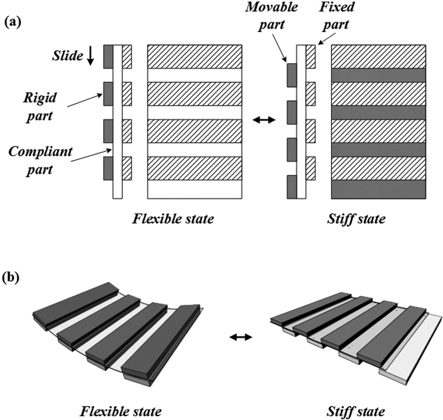
Concept of dual-stiffness mechanism by sliding: (a) schematic drawing and (b) examples of sliding mechanism.
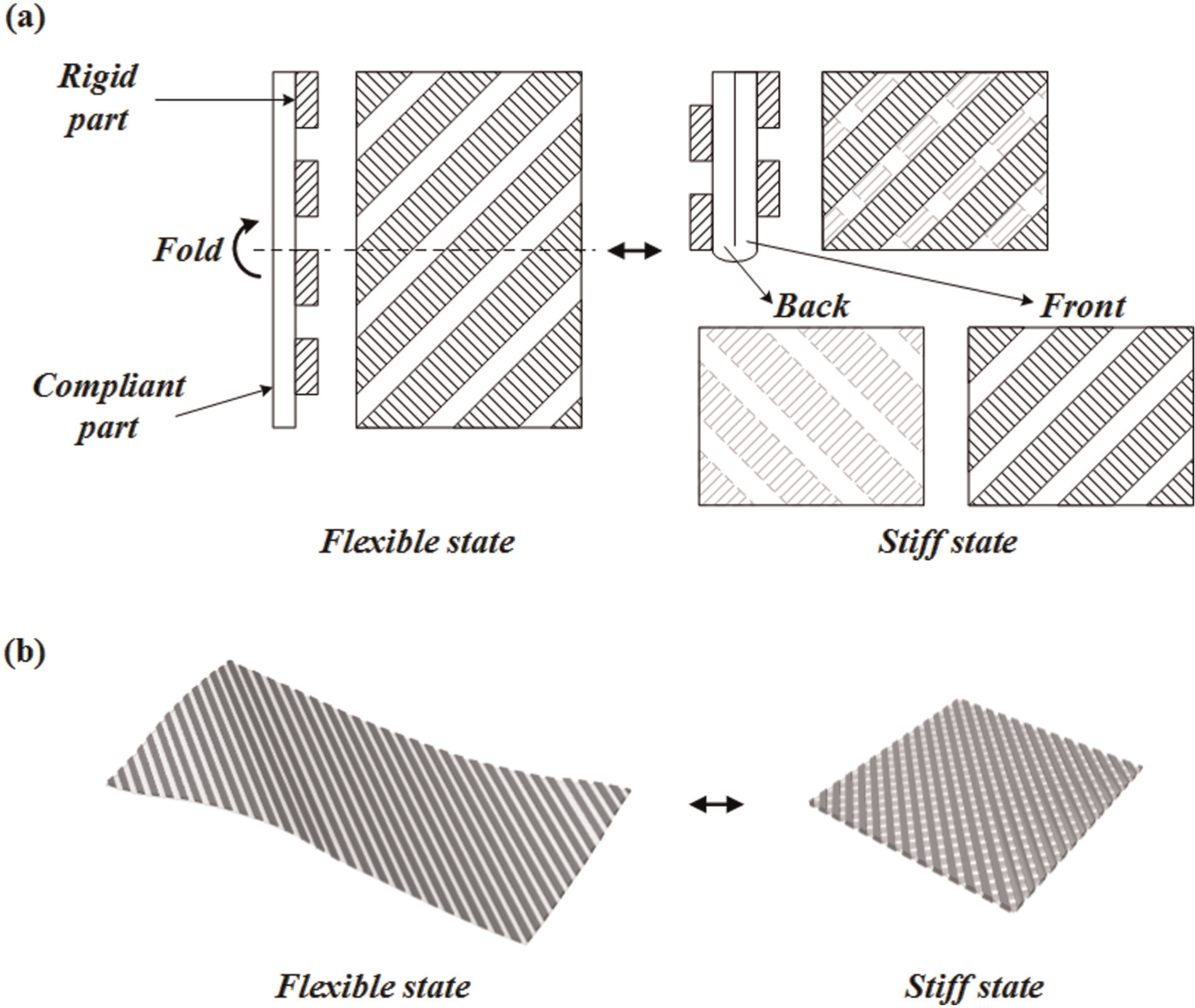
Concept of dual-stiffness mechanism by folding: (a) schematic drawing and (b) examples of folding mechanism.
To change the stiffness of the structure by reconfiguring the rigid segments, we considered two mechanisms: a sliding mechanism and a folding mechanism. As shown in Figure 2(a), one of the rigid parts (left rigid parts) can slide, and it is not attached to the compliant part. The other rigid parts (right rigid parts) are fixed and attached to the compliant part. When the movable rigid part is located in the same position as the fixed part, the structure is easily bent, and it is in the flexible state. If the movable rigid part slides and is located between two fixed rigid parts, the structure cannot be bent, and it is in a stiff state. By reconfiguring the rigid segments by sliding, the stiffness of the structure can be varied. When the structure is in the stiff state mode, the compliant part cannot be bent, and the entire structure maintains its original shape, as shown in Figure 2(b).
Figure 3(a) shows a folding mechanism that can be used to vary the stiffness of the structure. Rigid parts are arranged in a diagonal line and attached on only one side. To change the stiffness state from the flexible state to the stiff state, the middle part of the compliant material is folded. Because of the diagonal arrangement of the rigid parts, when the structure is folded, the rigid parts on the front side and backside cross. Thus, the bending of the compliant part is constrained, and it is in a stiff state because of the folding mechanism. In the unfolded condition, the structure can be freely bent and rolled, and it is in a flexible state, as shown in Figure 3(b). By reconfiguring the rigid segments by folding, the bending of the compliant part is constraint. Therefore, the stiffness of the structure can be varied.
As mentioned earlier, the stiffness of the dual-stiffness structure is dominated by the reconfiguration of the rigid segments. The stiffness of the system can be varied by the reconfiguring mechanism. Therefore, we can apply or create an appropriate mechanism based on the operating condition and the design of the entire system.
Design and fabrication of dual-stiffness structure
Design of dual-stiffness structure
Based on hybrid structures that combined rigid and flexible materials, dual-stiffness structures with two mechanisms, the sliding mechanism and the folding mechanism, were implemented. By varying design parameters, the distance between the rigid parts and their width, eight different dual-stiffness structures were manufactured using a layering process.
Dual-stiffness structure with sliding mechanism
To apply the sliding mechanism, the basic design concept of the dual-stiffness structure was modified as shown in Figure 4. Rigid parts were arranged on both sides of the compliant part, and each rigid part was divided into several segments such as a movable part and a fixed part, as described in Figure 4(a). The movable parts and fixed parts were not bonded, and the movable parts freely slid on the compliant part. The fixed parts were attached to the compliant film using an adhesive film, but the sliding parts were not attached to the main compliant film. To slide all the movable parts together, an additional compliant film was installed between the upper sliding parts and the compliant film, and the upper sliding parts were attached to this additional compliant film with an adhesive film. The upper and lower sliding parts were connected using a fastening component, which was glued with an adhesive. To guide the distance and direction of the sliding, a narrow slit was made in the compliant film, and the sliding part moved along this slit, as described in Figure 4(c). The length of the slit was determined by the distance between the rigid segments lf, and the width of the slit was regulated to the thickness of the fastening component. The movable range of the sliding segments was determined by the length of the slit. Four different dual-stiffness structures with the sliding mechanism were fabricated by altering the distance between the rigid segments lf, whereas the length of the rigid segments lr remained constant. The design parameters are listed in Table 1. The size of block is same as the length of the rigid segments. The ratio between the length of the rigid segments and the distance between the rigid segments is defined as the ratio of the rigid portion as follows
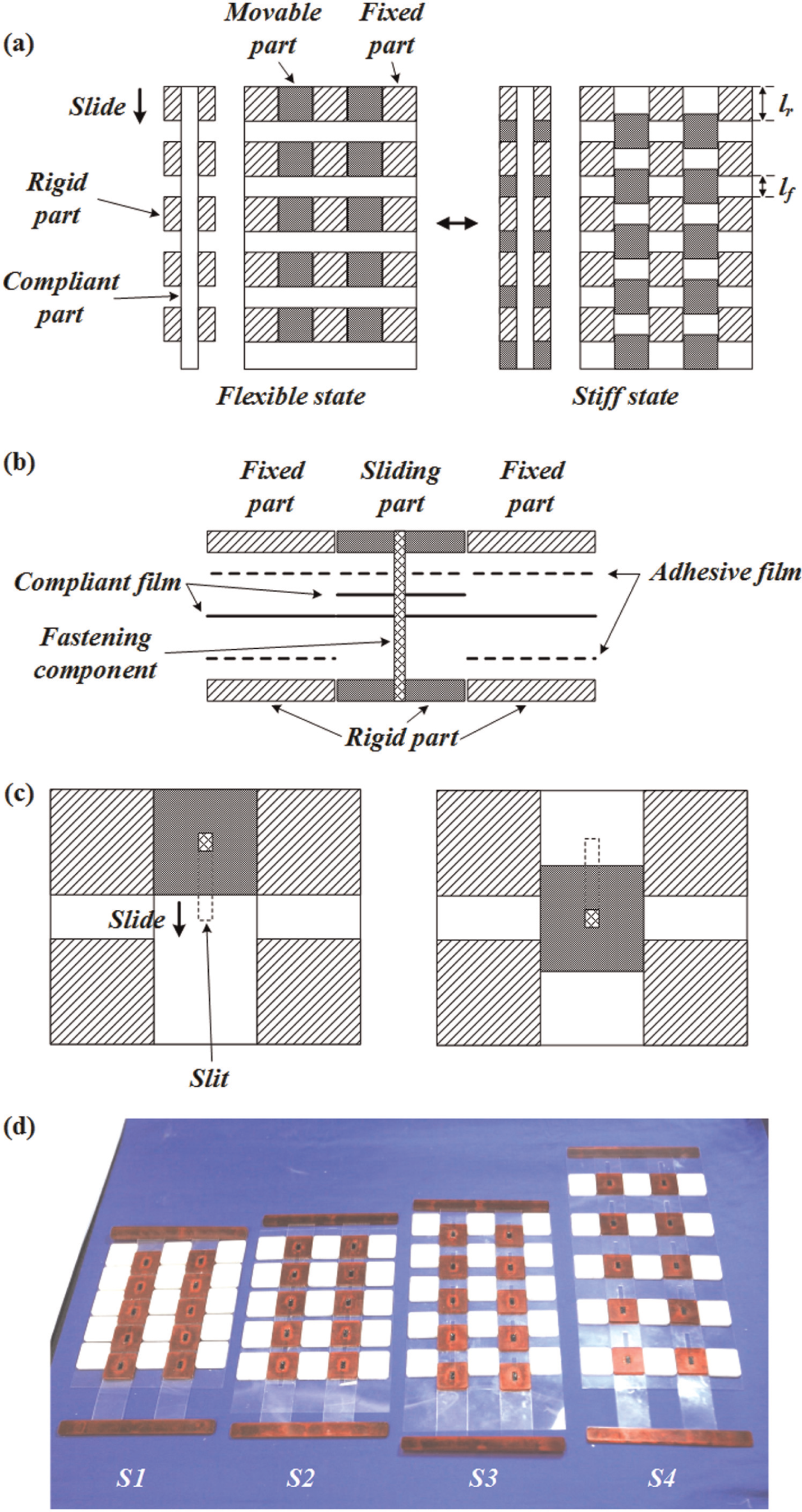
Dual-stiffness structures with sliding mechanism: (a) schematic drawing of entire structure, (b) cross-sectional drawing of structure, (c) explanation of sliding mechanism, and (d) actual structures.
Design parameters of dual-stiffness structure with sliding mechanism.
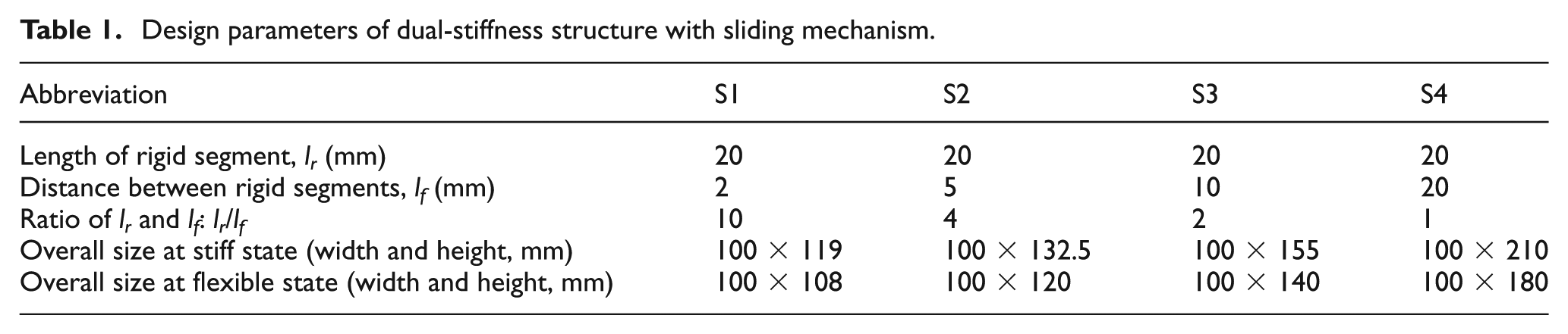
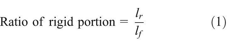
where lr is the length of the rigid segments, and lf is the distance between the rigid segments. We assumed that the stiffness of the structure could increase depending on the ratio of the rigid portion. Based on the ratio of the rigid portion, we can hypothesize that S1 is the stiffest, whereas S4 is the most flexible.
Dual-stiffness structure with folding mechanism
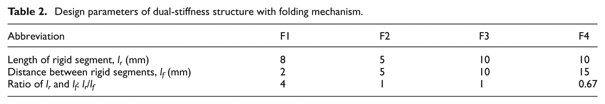
Using the basic concept of the dual-stiffness structure with the folding mechanism, four different dual-stiffness structures were fabricated as shown in Figure 5. The overall size of all the dual-stiffness structures with folding mechanism is 100 mm wide and 200 mm long. The lengths of the rigid segments lr and compliant segments lf are defined in Table 2. The rigid components were arranged in a 45° diagonal line and attached on only one side. To be able to fold the structure, the rigid segments were cut along a dashed line. When the structure was folded, the rigid segments on the front side and backside crossed perpendicularly. The ratio between the width of the rigid segments and the width of the compliant segments is also defined as the rigid portion, and this ratio is the same as the ratio between the area of the rigid segments and the area of the compliant segments. We assumed that the stiffness of the structure increased as the ratio of the rigid portion increased. Using the ratio of the rigid portion, we can hypothesize that F1 is the stiffest, and F4 is the most flexible. Because F2 and F3 have the same ratios for the rigid portion, the stiffness values of these structures may be the same.
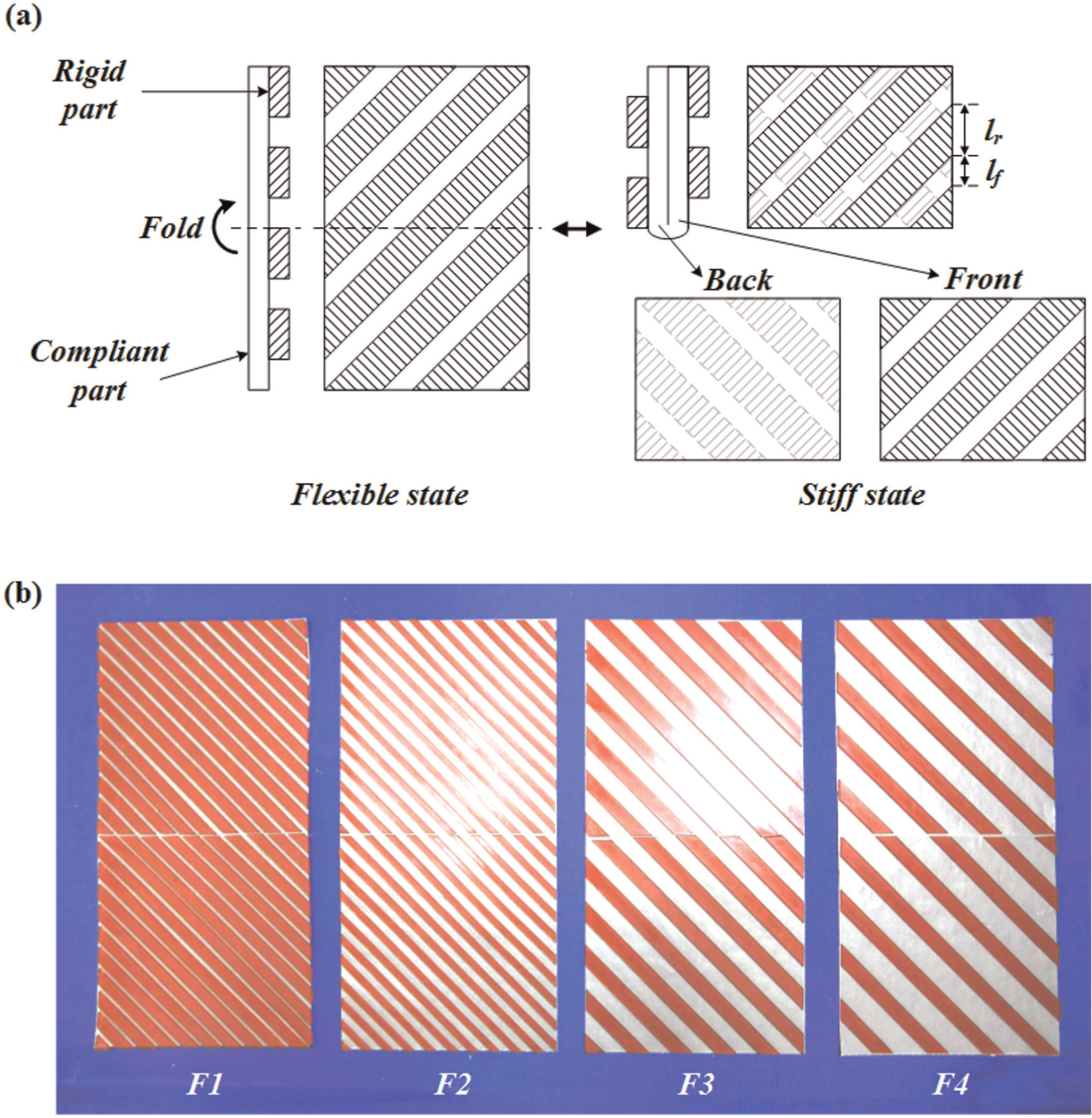
Dual-stiffness structures with folding mechanism: (a) schematic drawing of entire structure and (b) actual structures.
Design parameters of dual-stiffness structure with folding mechanism.
Fabrication: layered manufacturing process
From the beginning, the fabrication process was considered in the design of the dual-stiffness structure. To apply the dual-stiffness structure to a large area, a simple manufacturing process is an important issue. This structure is based on a two-dimensional surface. Therefore, we considered a layered manufacturing process. As mentioned in the previous section, rigid parts, compliant films, and an adhesive film (5316K; Coretec Co.) are needed to fabricate the dual-stiffness structures. Acrylic (thickness: 1.2 mm) is used as the rigid component. Polyethylene terephthalate (PET, thickness: 0.05 mm) is used as the compliant component for the sliding structure, and paper is used as the compliant component for the folding structure. For the compliant component of the folding structure, any compliant sheet can be used, such as polymer film or paper. In our folding mechanism, the paper was used for the ease of fabrication and folding. The paper has a good bonding property, and it can be easily folded compared to other compliant materials. Polymer film could improve the robustness of the structure.
For the dual-stiffness structure with the sliding mechanism, two rigid layers, two adhesive layers, and two compliant layers are laminated with one fastening component, as shown in Figure 4(b). The fabrication process follows the order shown in Figure 6. First, an adhesive film is attached to the acrylic plate, and it is cut by an ultraviolet (UV) laser (M300; Universal Laser Systems Inc.), as shown in Figure 6(a) and (b). The adhesive film is not attached to the acrylic plate, which is used as a rigid segment for sliding. According to the design, an alignment plate for the rigid segments and PET film is also cut using the UV laser (Figure 6(c) and (d)). The PET film has narrow slits for guiding the sliding segments. Using this alignment plate, the fixed segments are arranged, and the PET film is attached to the rigid segments on one side at a time (Figure 6(e) and (f)). At this time, each layer is aligned using the pin alignment holes. Using the adhesive film, the sliding segments, which are used on the upper layer, are attached to the PET film. The fastening component is bonded to the sliding segments for the lower layer using a high-strength adhesive, as described in Figure 6(g). The fixed part and sliding part are combined using the alignment plate and the fastening components (Figure 6(h)). Finally, the dual-stiffness structure with the sliding mechanism is completed.
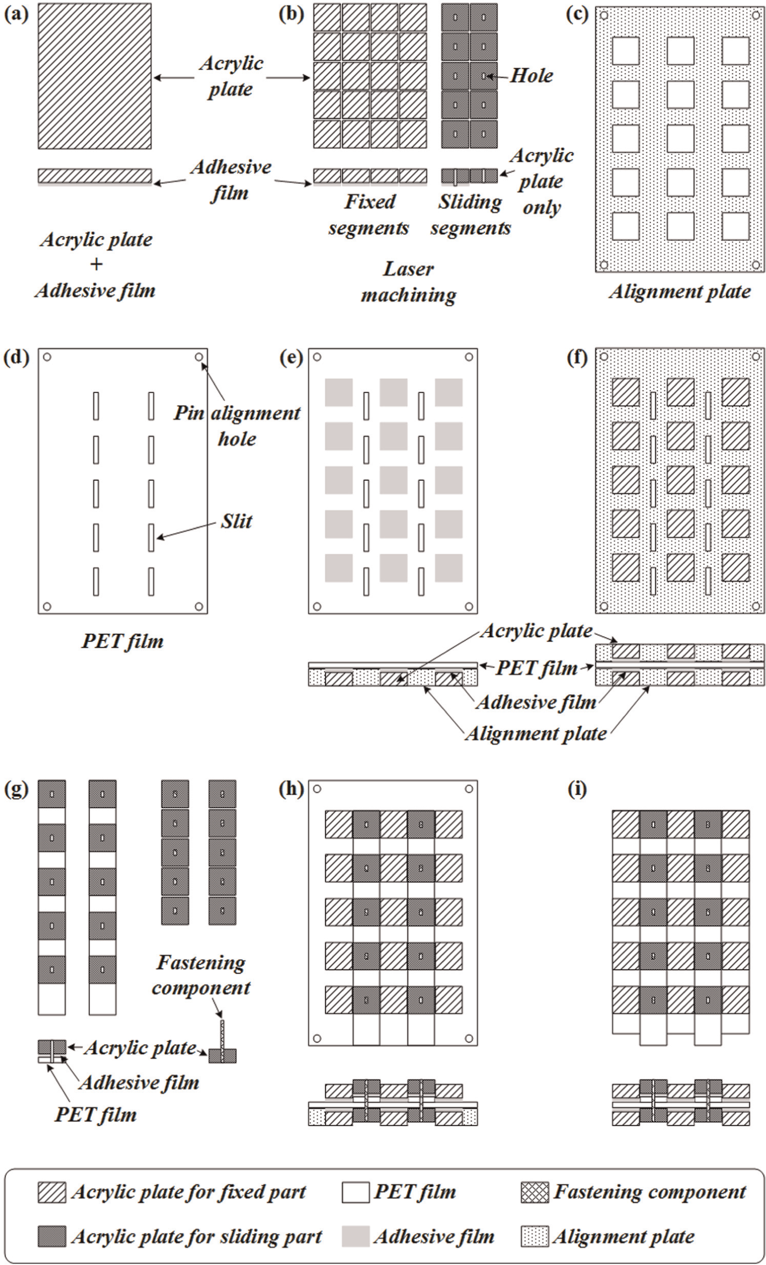
Fabrication process for sliding mechanism: (a) acrylic and adhesive film, (b) laser machining, (c) alignment plate, (d) PET film with laser machining, (e)–(f) fixation of rigid segments on both sides, (g) fabrication of sliding segments, (h) assembly of fixed component and sliding component, and (i) final prototype.
When the fastening component is attached to the sliding segments of the upper layer, it is important to note that the fastening component should not be attached to the PET film. When the sliding structure is designed, the tolerance between the fixed segment and the sliding segment should be considered for smooth sliding. However, if the tolerance is large, the flexible film may not be constrained by the rigid component, which will reduce the stiffness of the system. On the other hand, if the tolerance is small, it may be difficult for the sliding segment to move along the slits.
Figure 7 gives an overview of the fabrication process. Pins, which are used for aligning the plates, are installed into a base plate, and each layer has pin alignment holes. The PET film is located between the upper layer and lower layer and is attached to the fixed components using the adhesive film. For precise alignment, two alignment plates are used.
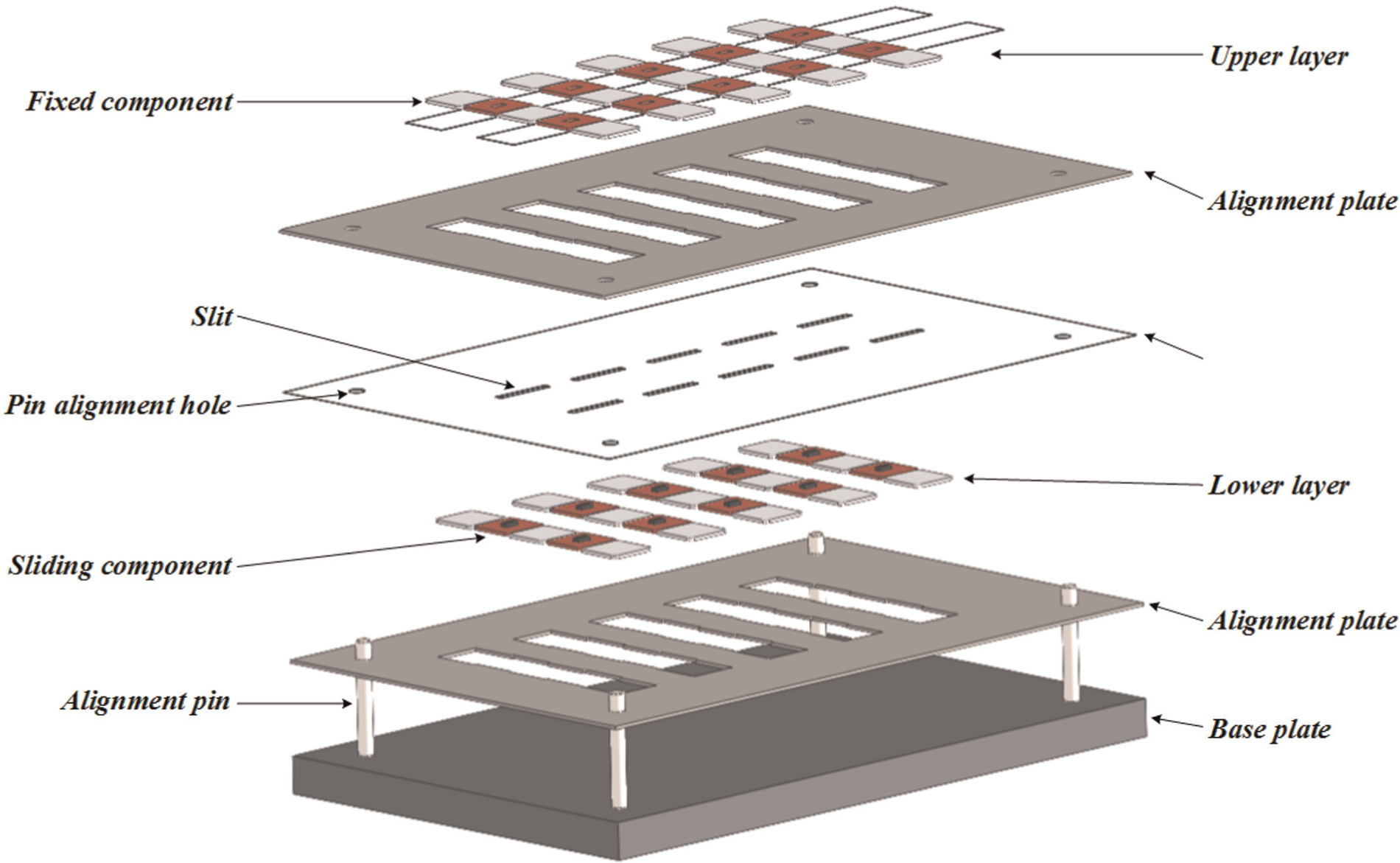
Simple overview of fabrication process.
The fabrication process for the folding mechanism is much simpler. One rigid layer, one adhesive layer, and one flexible layer are laminated as shown in Figure 8. The fabrication proceeds in the following order: acrylic plate, adhesive film, and paper. The adhesive film is attached to the acrylic plate and is cut by the UV laser as explained earlier. Two alignment plates are used for precise attachment.
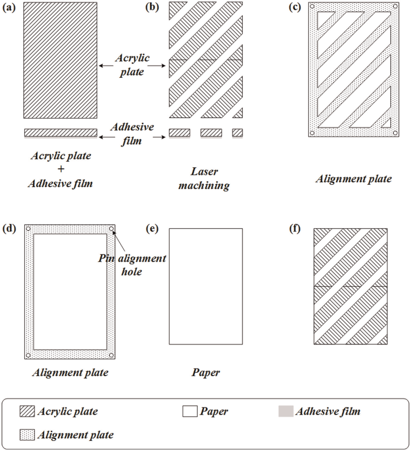
Fabrication process for folding mechanism: (a) acrylic and adhesive film, (b) laser machining, (c) alignment plate for rigid segment, (d) alignment plate for compliant segment, (e) paper, and (f) final prototype.
The layering process enables the integration of rigid segments with flexible components, which can be joints in the system (Cho et al., 2009). Thus, this layered manufacturing process is suitable for a two-dimensional multi-layer design, and it can facilitate speedier mass production of dual-stiffness structures. Using laser machining, the rigid material and compliant material are cut precisely and laminated to create the integrated structure. Therefore, the dual-stiffness structure can be easily made by cutting and laminating processes. These processes can also be applied to a meso-scale structure with compliant joints, because conventional rotating joints using pin joints are hard to manufacture on the meso-scale.
Analysis and experimental results
Analysis and experimental results with perfectly bonded structure
To analyze the bending of dual-stiffness structures with the sliding mechanism, we prepared three simplified structures with perfect bonding between the rigid segments and the flexible part, which had the same design parameters as listed in Table 1. These simplified structures were designed as shown in Figure 9. In contrast to previous structures, the arrangement of the rigid segments was the same as the stiff state of the dual-stiffness structures with the sliding mechanism, but all the rigid segments were attached to the compliant part. Therefore, the rigid segments were perfectly bonded to the compliant part, whereas the sliding segments of the dual-stiffness structures were bonded to the fastening component, not the compliant part. Even though the rigid parts and flexible film were perfectly bonded, the structure was bent.
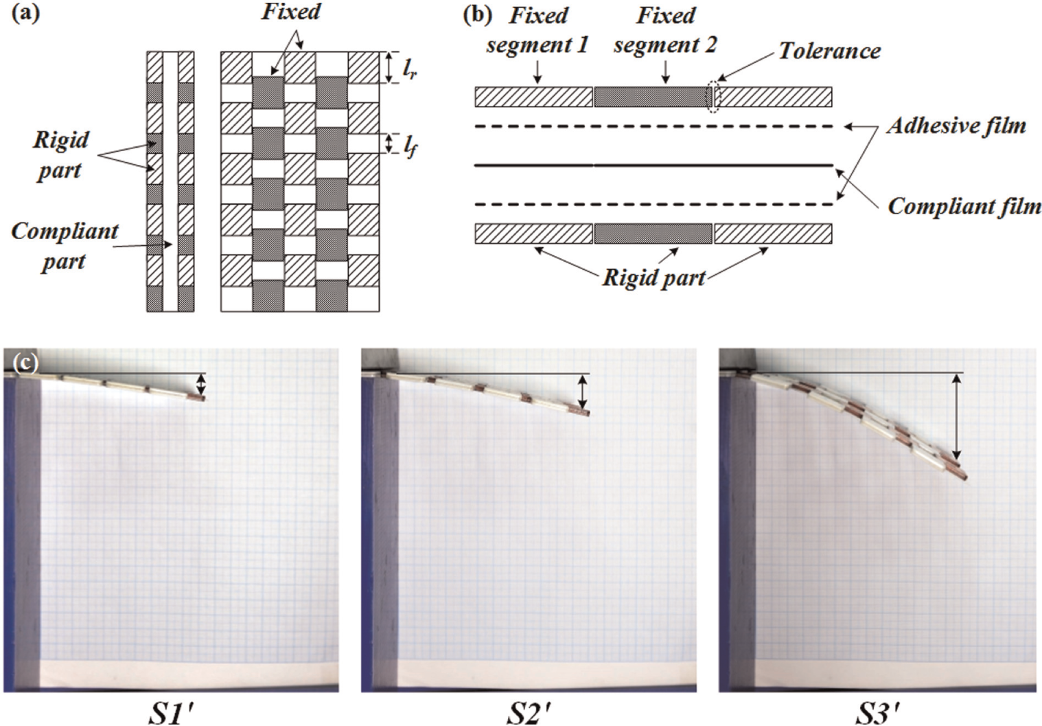
All rigid parts are attached to compliant material. Thus, the structure has no sliding mechanism: (a) schematic drawing of structure, (b) cross-sectional drawing of structure, and (c) bending experiment.
We measured the deflections of the structure, as shown in Figure 9(c). The experimental results are listed in Table 4.
We assumed that the dual-stiffness structures bent as a result of the length of the rigid segment, lf, and the tolerance between fixed segment 1 and fixed segment 2. As mentioned earlier, the tolerance made it possible for the dual-stiffness structures to slide against each other. We also assumed that there was no gap between fixed segment 1 and fixed segment 2, but they were not bonded.
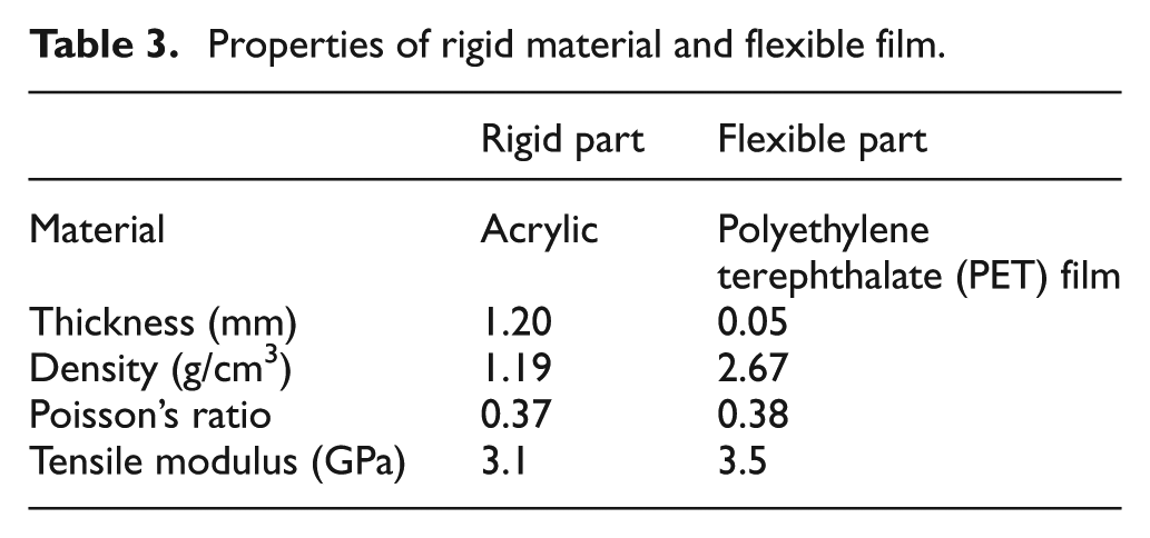
To verify that the results of this bending experiment for the structures depended on the distance between the rigid segments, a finite element analysis was carried out using three different distances: 2, 5, and 10 mm. The finite element was analyzed using a general-purpose finite element program: ABAQUS. The finite element model consisted of the flexible part and rigid parts, which were uniformly arranged. A large number of S4R (a 4-node doubly curved thin or thick shell, reduced integration, hourglass control, finite membrane strains) elements were used, according to the distance between the rigid parts (2950 elements: 2 mm; 3400 elements: 5 mm; 3950 elements: 10 mm), in the case of the flexible part, and 1200 C3D8R (an 8-node linear brick, reduced integration, and hourglass control) elements were used in the case of rigid part. Table 3 lists the properties of the rigid and flexible parts.
Properties of rigid material and flexible film.
As shown in Figure 10, perfect bonding between the flexible and rigid parts was simulated using a tie constraint, and the contact between the sides of the rigid parts was assumed to be frictionless. One side of the structure was clamped, and the deflection of the structure under gravity has been simulated. The simulation considered the nonlinearity of the structure to reflect the nonlinearity of the deflection.
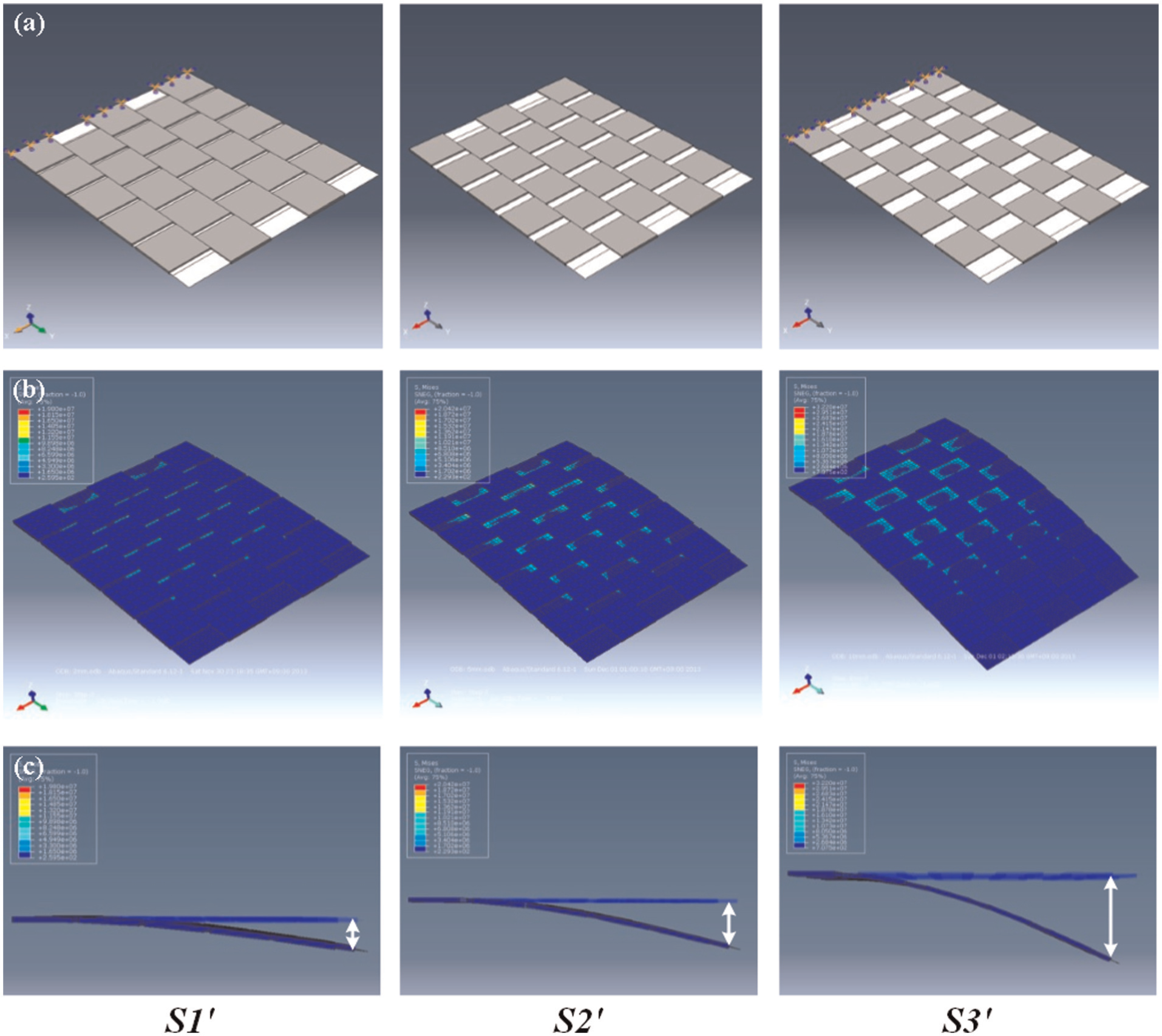
Analysis of structures without sliding mechanism: (a) FEM models, (b) flexible film bending simulation, and (c) deflection of structures.
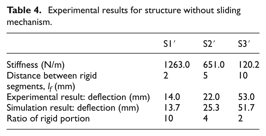
The deflection of the structures occurred in the stiff state, and it increased in proportion to the distance between the rigid segments. A shear strain and stress concentration occurred in the flexible part around the line contact area between the rigid parts and the flexible film. According to this result, the deflection of the structure occurred as a result of the shear stain, even in the stiff state. The distance between the rigid segments disturbed the bending movement of the compliant part. The shear strain energy generated by the same shear strain increased as the overlapping area between the staggered rigid parts increased. As the distance between the rigid parts became larger, the shear strain with the same shear strain energy became smaller, and the deflection of the structure decreased. The stiffness of the structure varied depending on the distortion. The measured and simulated data are compared in Table 4. The stiffness of each structure was measured using a universal testing machine, R&B Micro load RB302, with a 1-kg force transducer. Three-point bending test method was used to obtain the stiffness of the structure. The stiffness decreased with a decrease in the ratio of the rigid portion, which was the ratio of the lengths lr and lf. Overall, the estimated results were in good agreement with the measured results.
Experimental results for structure without sliding mechanism.
Experimental results for dual-stiffness structures with reconfiguring mechanisms
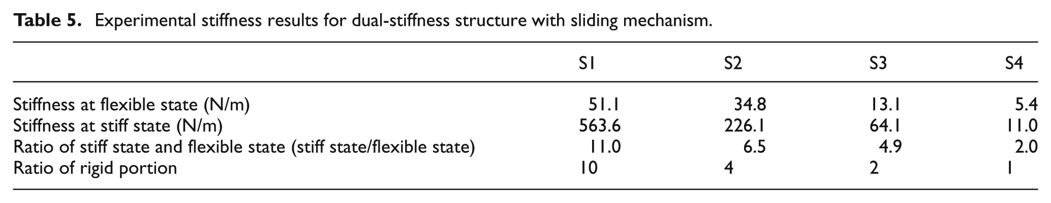
The stiffness of the dual-stiffness structures was measured using a universal testing machine, and Table 5 lists the experimental results for the dual-stiffness structure with a sliding mechanism. The stiffness decreased with a decrease in the ratio of the rigid portion, which was the ratio of the lengths lr and lf. As mentioned earlier, the stiffness of the dual-stiffness structure was dominated by the rearrangement of the rigid segments. Thus, the ratio of the rigid portion determined the stiffness of the system. The stiffness difference between the stiff state and the flexible state also decreased as the ratio of the rigid portion decreased. Therefore, the stiffness of the structure could be adjusted using the ratio of the rigid portion. The stiffness of the structure rapidly dropped at the stiff state compared to the flexible state, as shown in Figure 11.
Experimental stiffness results for dual-stiffness structure with sliding mechanism.
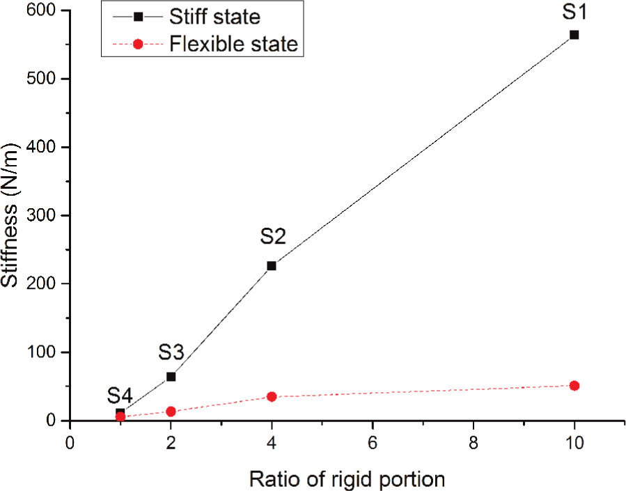
Experimental stiffness results for dual-stiffness structure with sliding mechanism. The solid line stands for the stiff state, and the dashed line stands for the flexible state.
As shown in Tables 4 and 5, the stiffness of the perfectly bonded structure was larger than that of the dual-stiffness structure with sliding mechanism. The lower stiffness of the dual-stiffness structure with sliding mechanism was caused by a gap between the rigid part and the flexible part. The stiffness of the perfectly bonded structure is the maximum stiffness case for the proposed structure. The stiffness of the structure decreases when the gap increases. In this research, we focus on the functionality of the structure with variable stiffness mechanism, so the sliding mechanism was considered even though the stiffness of the structure was lost due to the gap. To increase the stiffness of the structure, further research related to the appropriate tolerance is needed.
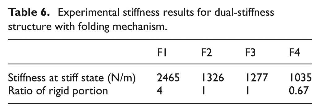
Table 6 lists the experimental results for the dual-stiffness structure with the folding mechanism. The stiffness of the flexible state was not tested because the structures were too flexible to measure the stiffness with the universal testing machine. The stiffness decreased with a decrease in the ratio of the rigid portion, which was the ratio of the lengths lr and lf, just as in the previous experimental results. As previously estimated, the stiffness of F2 was approximately equal to that of F3, as listed in Table 6 and shown in Figure 12. This was because F2 and F3 had the same ratio of the rigid portion and the same area of rigid segments. Therefore, the stiffness of the structure can be adjusted based on the area ratio of the rigid segments.
Experimental stiffness results for dual-stiffness structure with folding mechanism.
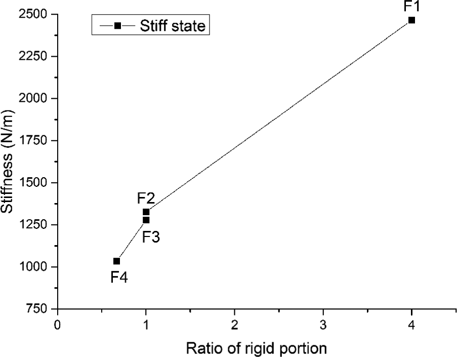
Experimental stiffness results for dual-stiffness structure with folding mechanism at stiff state.
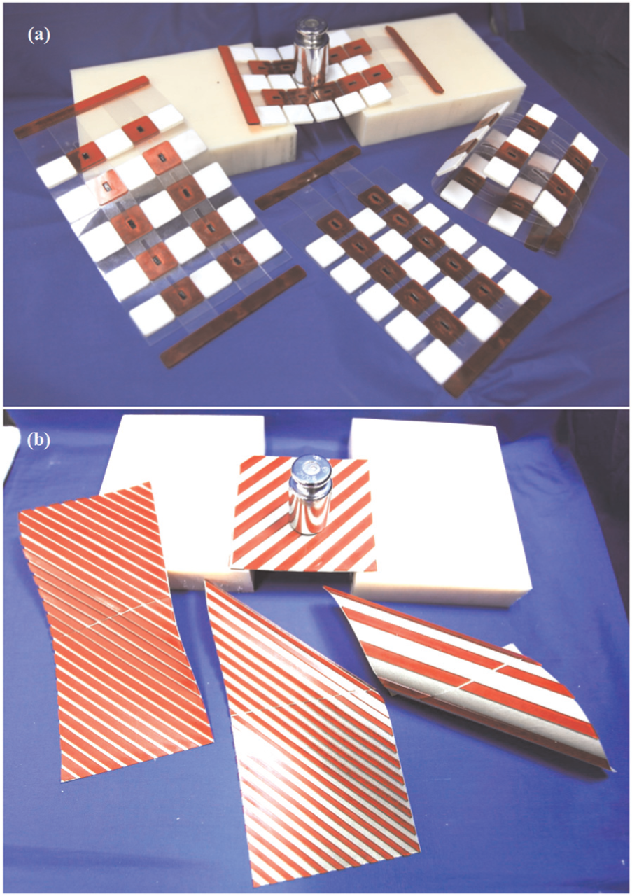
The features of the dual-stiffness structure could be verified with a bending test, as shown in Figure 13. According to the experimental stiffness results, the deflection of the structure was varied. These deflection results are listed in Table 7. The reconfiguration of the rigid segments prevented the bending of the flexible segments, and it increased the stiffness of the structure. When the stiffness of the structure decreased from S1 to S4, the deflection of the dual-stiffness structure increased in both cases: the flexible case and the stiff case. The difference in deflection between the stiff state and the flexible state decreased as the stiffness difference decreased, as shown in Table 5.
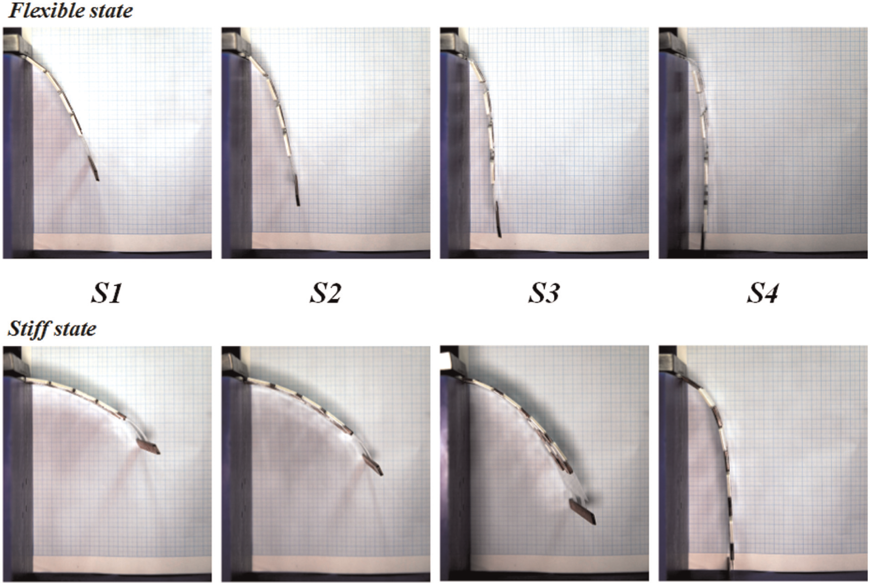
Bending experiment for dual-stiffness structure with sliding mechanism.
Deflection results for dual-stiffness structure with sliding mechanism.
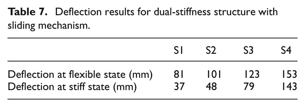
The final prototypes of the dual-stiffness structures are shown in Figure 14. When a system needs a simple design and large stiffness variation, the dual-stiffness structure can be a good solution. In the flexible state, the dual-stiffness structure can be easily rolled and folded, whereas in the stiff state, it can be rigid enough to serve as a frame in a system. These dual-stiffness structures have deployable, foldable, and rigid features. Depending on the operating condition, the stiffness can be changed to obtain a stiff state or a flexible state. Therefore, the dual-stiffness structure can be applied to enhance the utilization of a system.
Final prototypes of dual-stiffness structures: (a) with sliding mechanism and (b) with folding mechanism.
Conclusions
Dual-stiffness structures were designed based on a hybrid structure that combined rigid and flexible materials. The rigid segments and compliant segments were alternated. The scheme and size of the structure could be easily changed using the design parameters. The stiffness of the structure was varied by reconfiguring the rigid segments, whereas the stiffness of previous variable stiffness structures was changed by varying the property of the compliant material. The stiffness of the dual-stiffness structure was varied using its rigid segments to constrain the bending of the compliant segments. Therefore, the reconfiguring mechanism of the rigid segments was important.
We considered two mechanisms to vary the stiffness of the structure: a sliding mechanism and a folding mechanism. Based on the hybrid structure, dual-stiffness structures were designed with sliding and folding mechanisms, and eight different dual-stiffness structures were manufactured using a layering process. The dual-stiffness structure was basically a two-dimensional multi-layer design, and the layered manufacturing process was suitable for this design. Using cutting and laminating processes with a laser cutting machine, the dual-stiffness structure could be easily and quickly fabricated.
To analyze the structure, a simplified structure was considered with perfect bonding between the rigid segments and the flexible part, with no sliding mechanism. We assumed that the dual-stiffness structures bent as a result of the length of the rigid segments in the vertical direction and the tolerance between two fixed segments in the horizontal direction. Using the finite element method, the structure was simulated, and the results were compared with the experimental results. According to the results, the deflection of the structure occurred because of the shear strain and stress concentration of the flexible film. The stiffness of the structure varied depending on the distortion of the flexible part, which is related to the shear strain.
The dual-stiffness structures were tested using a universal testing machine and a bending experiment. According to the experimental results, the stiffness of the structures decreased as the ratio of the rigid portion decreased. This was because the stiffness of the structure was dominated by the reconfiguration of the rigid segments. Therefore, the stiffness of the dual-stiffness structure could be adjusted using the ratio of the rigid portion. By constraining the compliant segments, the dual-stiffness structure could vary its stiffness between two conditions: the stiff state and the flexible state. This could be applied to various systems to improve the functionality of the structure by changing its state.
Further research on other novel mechanisms to reconfigure the rigid segments could enable the development of a different dual-stiffness structure. The proper reconfiguring mechanism should be based on the operating condition. A layered manufacturing process should also be developed for fast and simple fabrication. A parametric study of the dual-stiffness structure is also needed to estimate its behavior. The actuating method for changing the stiffness state, such as tendon drive mechanism, should be developed to actively change the stiffness of the structure. If various mechanisms are developed, and the manufacturing process is improved, the application potential of this dual-stiffness structure will be increased. Possible applications include flexible solar panel, flexible displays, or morphing wings which require variable stiffness for multi-functionality.
Footnotes
Declaration of Conflicting Interests
The authors declared no potential conflicts of interest with respect to the research, authorship, and/or publication of this article.
Funding
The author(s) disclosed receipt of the following financial support for the research, authorship, and/or publication of this article: This research was supported by the Priority Research Centers Program (No. 2014-048162), the Basic Science Research Program (No. 2014R1A1A2058928), and Leader Science Research Program (No. 2012R1A3A2048841) through the National Research Foundation of Korea(NRF) funded by the Korea government(ME and MSIP).