
Abstract
Under squeezing flow, magnetorheological fluid can undergo a strengthening phenomenon which results in a drastic increase of its yield stress. This behavior, also known as the super-strong effect, could be used to significantly increase the performance (e.g. torque-to-weight) of rotary magnetorheological fluid devices (e.g. brakes, clutches), but has yet to be exploited due to limited predictability of the phenomenon. To better understand the occurrence of the super-strong effect, a novel test bench capable of small amplitude oscillatory shear is designed to study the behavior of high-concentration magnetorheological fluid submitted to different simultaneous squeeze-shear conditions and magnetic field strengths. Experimental results, obtained up to 5 mm/s compression speed, show that the squeeze-strengthening effect can be correlated to the Péclet number when squeeze flow is dominant, suggesting that the super-strong behavior is governed by solid–liquid phase separation. This super-strong effect, however, is found greatly reduced when the super-imposed shear-rate approaches the squeeze-rate order of magnitude.
Keywords
Introduction
Background
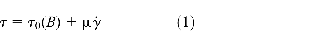
Magnetorheological fluids (MRF) are two-phase fluids, consisting of magnetically soft particles (e.g. iron) dispersed in a carrier liquid (e.g. oil). When submitted to a magnetic field, the apparent viscosity of MRF increases due to magnetization of the solid particles, which form chain-like structures as shown in Figure 1(a). In its most basic form, MRF behaves as a Bingham plastic (Figure 2(a)) with magnetic field (
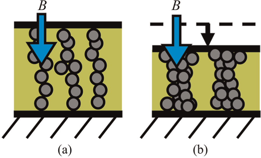
(a) MRF microstructure forms chain-like structures when magnetized. (b) During slow compression, particles can aggregate into stronger, thicker columns with higher yield stress.
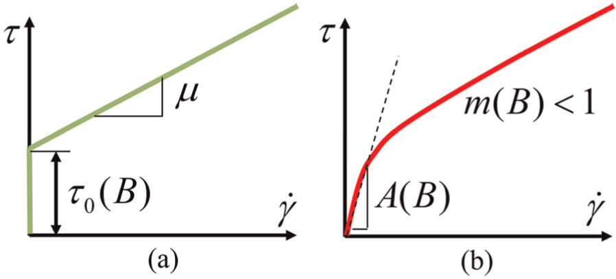
Rheological behavior of MRF: (a) Bingham model and (b) power-law model.
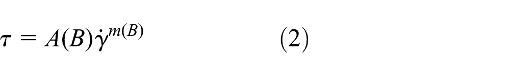
At low shear rates, however, MRF shows shear-thinning characteristics (see Figure 2(b)), which can be represented by a power-law relation (Jolly et al., 1999)
where
Regardless of the rheological model, MRF maximum achievable yield stress under pure shear conditions is limited to ∼100 kPa (Carlson and Jolly, 2000) due to maximal particle concentration and magnetic saturation (Ginder and Davis, 1994). Due to limited yield stress, MRF device (e.g. brake, clutch) performance-metrics, such as torque-to-weight ratio, are almost exclusively optimized through the geometrical properties of the magnetic circuit and shear interface (Avraam, 2009; Park et al., 2008). Hence, best rotary MRF devices reported to date achieve ∼70 Nm/kg (Gratzer et al., 2008).
Under slow compression, however, MRF particles have been shown to reorganize into strong columns, as shown in Figure 1(b), with increased yield stress up to 1500 kPa (Zhang et al., 2004). This squeeze-strengthening phenomenon, also known as the super-strong effect (Tao, 2001), could drastically increase the torque-to-weight ratio of MRF devices, but has not yet been used in practical applications due to limited understanding and predictability of the phenomenon. Moreover, its feasibility in rotary (shear-type) devices is questionable, as it has been demonstrated that super-imposing squeeze motion to a shearing flow does not always result in an increase in MRF yield stress (Kulkarni et al., 2003). To our knowledge, the only recorded design attempt of a super-strong device is an MRF brake, which uses a double magnetic circuit to compress the MRF during shear motion (Sarkar and Hirani, 2013). Experimental results show a twofold increase in yield stress due to squeeze motion. However, limited information does not allow the weight or dynamic performance of the device to be established.
To date, relevant studies discussing the occurrence of super-strong behavior in MRF mainly provide static yield-stress measurements after compression (Tao, 2001) or quasi-static dynamic data for slow loading rates (e.g.
In the field of electrorheological fluids (ERF), a super-strong effect has also been recorded during slow compression tests where solid–liquid separation (or filtration) is visually witnessed (McIntyre, 2008). In such conditions, the yield-stress increase is attributed to both the increase in particle concentration due to filtration and the increase in structural rigidity due to reorganization of particles under the electric field (Lynch et al., 2006). Qualitative observations suggest that the occurrence of filtration might relate to the Péclet Number (McIntyre and Filisko, 2010), but the Péclet number has never been clearly linked to the occurrence of the super-strong behavior in MRF.
Proposed research
The goal of this study is thus to provide an experimental understanding of the occurrence of the super-strong effect during the simultaneous squeeze-shear of high-concentration MRF. A novel test bench, capable of compression, rotation, and small amplitude oscillatory shear (SAOS), is designed to study the evolution of MRF yield stress under different operating conditions. Experimental results are consolidated and compared to the Péclet number to provide insight into the underlying behavior.
Experimental results show a strong correlation between the super-strong effect and the Péclet number when squeeze flow is dominant over shear flow, suggesting that the super-strong behavior is governed by solid–liquid phase separation. In such conditions, a super-strong behavior is demonstrated up to 5 mm/s compression speed, which is ∼100× faster than reported in previous studies. The super-strong effect, predicted by the Péclet number, however, is found greatly reduced as super-imposed shear-rate approaches the order of magnitude of the squeeze rate.
Theory
Péclet number
The Péclet number (
where
where
where

Compression of two-phase fluids between circular plates at speed V (a)
Assuming a power-law behavior (see equation (2)) and approximating the shear rate with the compression speed,
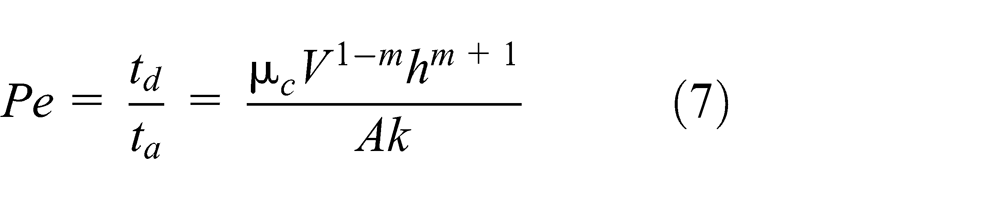
During compression, when the Péclet number is high (
When the Péclet number is low (
Although the Péclet number is based on average fluid flow properties, a transition in rheological behavior occurs during compression tests when the diffusive and advective time-scales are of the same order of magnitude (Kaci et al., 2011). By posing
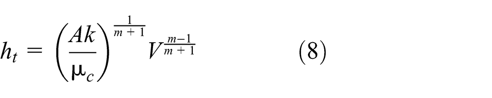
Equation (8) shows that transition between bulk flow and filtration is dictated by material properties (
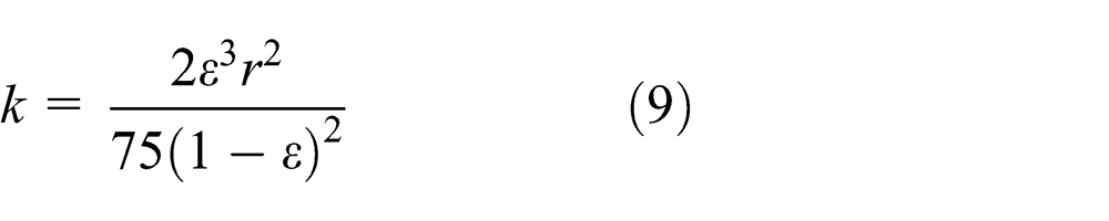
While equation (9) is generally used for packed beds of uniformly sized particles and while the dependence of Darcy permeability (
Rheological behavior of yield-stress fluids
During the compression of high-concentration non-magnetic two-phase fluids, the transition between advective and diffusive behavior is generally identified as a sharp increase in compressive force due to close particle packing (Kaci et al., 2011). For MRF, however, an accurate model of its complex non-Newtonian behavior may be required to properly identify a change in rheological behavior, since both advection and diffusion can impact the axial force in a similar way (but to a different extent), increasing the axial force as gap height is decreased.
In this work, the transition between advective and diffusive flow is thus monitored using MRF yield-stress measurements in the rotational direction, rather than in the axial direction, as yield stress in the rotational direction is expected to evolve differently for high and low Péclet numbers. When the Péclet number is high, it is expected that MRF behave as typical yield-stress materials (e.g. soft glassy materials), which offer no yield resistance in the rotational direction while material is flowing in an orthogonal direction (Ovarlez et al., 2010). However, during slow compression of MRF, where filtration is dominant (low Péclet number), it has been demonstrated that MRF can still transmit yield stress in shear direction (De Vicente et al., 2011).
As shown in Figure 4, yield stress is measured by super-imposing SAOS during compression tests and by monitoring the imposed displacement (
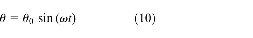
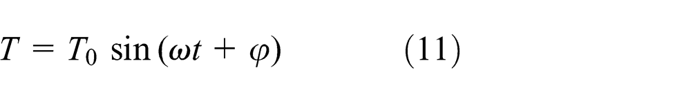
where
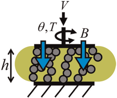
Monitoring of yield stress by super-imposed SAOS during the compression of MRF submitted to magnetic field (B).
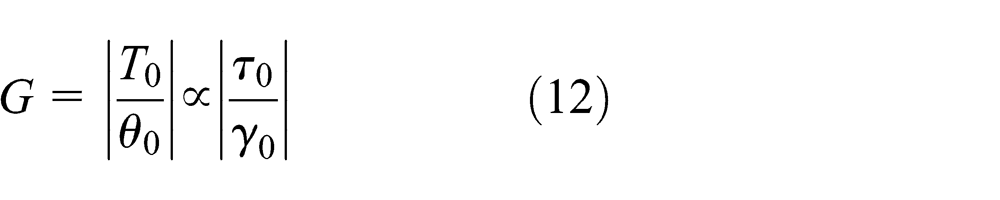
As depicted in Figure 5, the complex shear modulus (
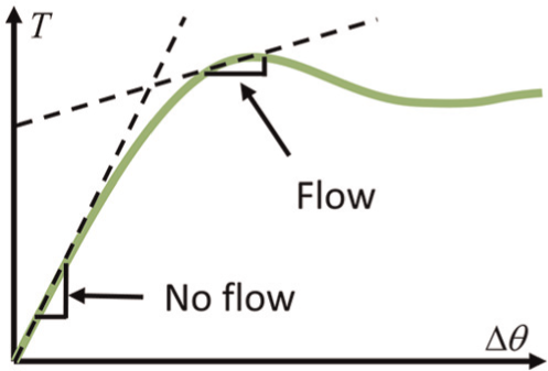
SAOS measurement according to material flow characteristics. When material is not flowing, SAOS is a measure of apparent rigidity. When material is flowing (induced by squeeze or shear), the SAOS measurement is indicative of viscosity.
Methodology
Test apparatus
To experimentally investigate the behavior of MRF under simultaneous squeeze-shear, a disk-type clutch capable of independently shearing and squeezing MRF is designed as shown in Figure 6. The rotary part of the clutch (shown in gray) is connected to a 160 Nm direct-drive motor through a 250 Nm in-line torque-transducer and high torsional-rigidity couplings. A rotary digital encoder (80,000 pulses/turn) is mounted near the clutch interface to measure the input angle of SAOS.
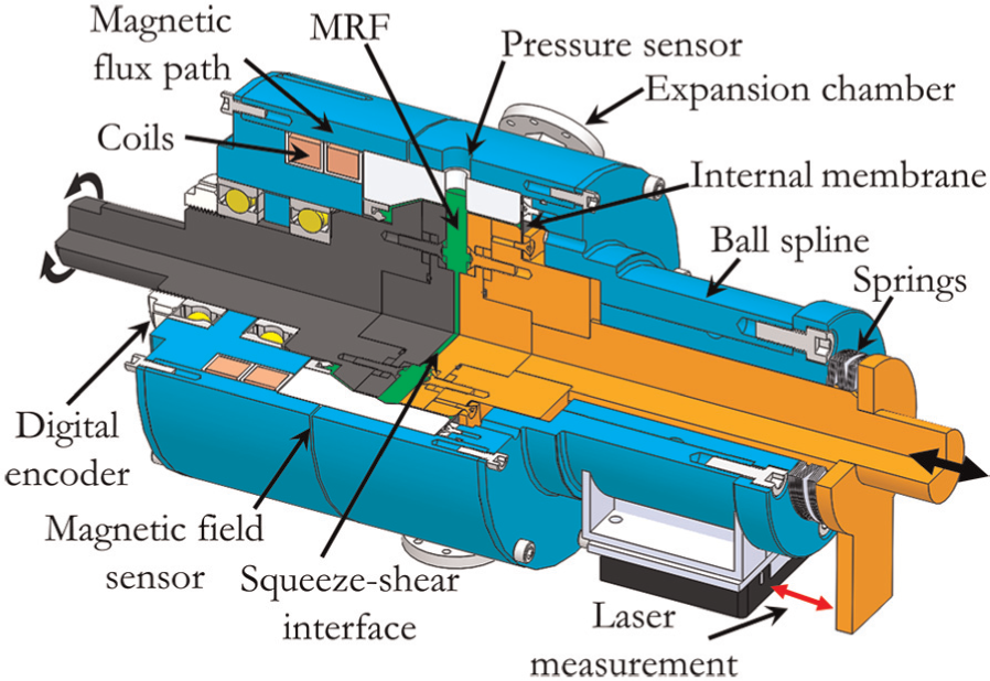
Simultaneous squeeze-shear clutch with disk interface.
Linear displacement (shown in orange) is controlled by a ball-screw linear actuator and guided by a pre-loaded ball-spline, mounted concentrically with the outer frame (shown in blue) of the clutch to ensure parallelism of the squeeze-shear interface. Springs are mounted in parallel with the linear section of the clutch in order to avoid control issues due to actuator backlash. MRF gap height is monitored by a laser position sensor (1 µm resolution) via a steel plate that moves with the inner ball-spline. Axial force is recorded by a 22-kN in-line load cell.
While the clutch is designed for interchangeable squeeze-shear interfaces (e.g. disk and annulus), this study focuses on identical disk-type plates with 25.4 mm in outer radius (
Three peripheral expansion chambers and one internal membrane are used to minimize pressure increase during compression tests. Nevertheless, pressure can reach up to 10 psi when compression is performed at high speed (e.g. 5 mm/s). A pressure sensor is thus mounted at the outer radius in order to monitor pressure and correct the axial force measurement, when required.
As shown in Figure 7, two coils are used to generate a maximal magnetic field (<2 T) at the MRF shear interface, while minimizing flux leakage across other surfaces. With minimal flux leakage, all flux lines crossing the shear interface also cross the circumferential air gap (1 mm thickness), thus providing a means of monitoring the magnetic field at the shear interface. Experimental measurements performed without MRF in the clutch show that the magnetic field at the shear interface is twice that measured at the air gap. Although flux leakage can slightly alter this result according to gap height and MRF permeability, a 2:1 constant ratio is assumed throughout this study.
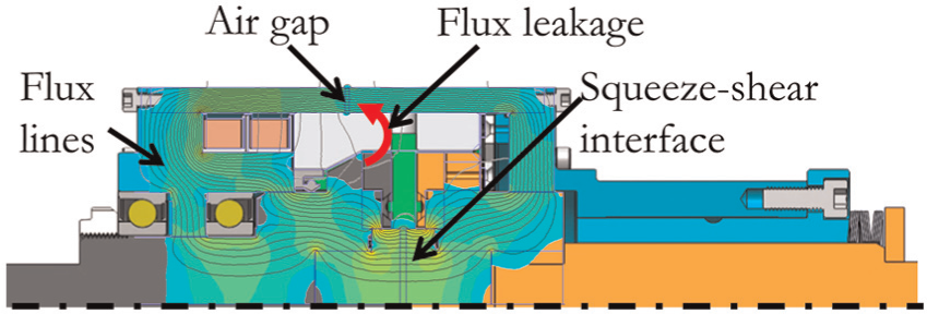
Axisymmetric view of the simultaneous squeeze-shear clutch and Finite Element Method Magnetics (FEMM) field simulation. Flux lines cross the shear interface with minimal leakage.
Materials
An MRF with high iron concentration (47% by volume) is made from carbonyl iron particles (3–5 μm radius) and a low viscosity (
Method
The clutch seen in Figure 6 is filled with 75 mL of MRF and is used for all tests described in this study. To avoid sedimentation and ensure proper mixing, MRF is sheared and squeezed at high speeds before each test for 15 s, while no magnetic field is applied.
Tests in pure shear are initially performed to identify the power-law parameters (
Static tests are then performed with super-imposed SAOS in order to map the MRF shear modulus
where
where
Altogether, compression tests combining 6 compression speeds spanning 2 orders of magnitude, from 0.05 mm/s to 5 mm/s and 6 magnetic fields, ranging from 0 to 1 T are performed (36 tests total). These tests are then repeated with super-imposed rotational speed ranging from 0 to 2 r/min.
SAOS frequency is set at 100 Hz for all tests in order to probe the MRF shear modulus several times per second, thus improving precision during tests at high compression speeds (e.g. 5 mm/s). This high frequency, combined with an angular displacement of 0.01°, limited by rotary encoder resolution, generally did not interfere with MRF behavior. During compression at very low speed and magnetic field, however, SAOS was shown to cause a maximal offset of ∼0.1 mm in the compression force curve, as compared to when no SAOS was used.
Results
In this section, the main experimental trends obtained from the pure shear, pure compression (+SAOS), and simultaneous squeeze-shear (+SAOS) tests are presented and described. Due to the number of tests, only the most relevant data are shown. All results, however, are analyzed, consolidated, and fully interpreted in the “Discussion” section.
Pure shear
Experimental behavior of MRF in pure shear is shown in Figure 8. As seen by the curve-fit (dashed lines) in log–log scale, the power-law model does not fully capture the MRF behavior over a wide range of shear rates. With parameters correlated at low shear rates (<5 s−1), a deviation is clearly seen at high shear rates (>5 s−1). In relative terms, this has more impact at low magnetic fields, where the yield-stress variation is significant compared to the peak yield stress seen at ∼2 s−1. Although this is a source of discrepancy for power-law models, this rheological model is chosen in order to compare results with the Péclet number derived from other studies regarding non-magnetic two-phase fluids. Best-fit parameters (
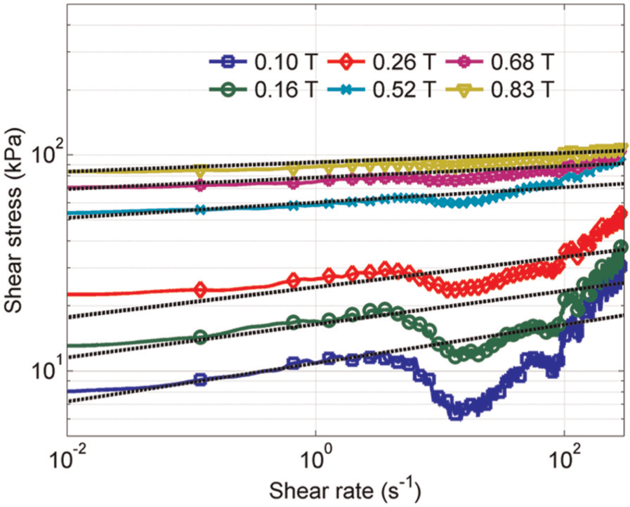
Power-law relation between shear stress and shear rate for MRF submitted to different magnetic fields.
MRF power-law parameters used in this study.
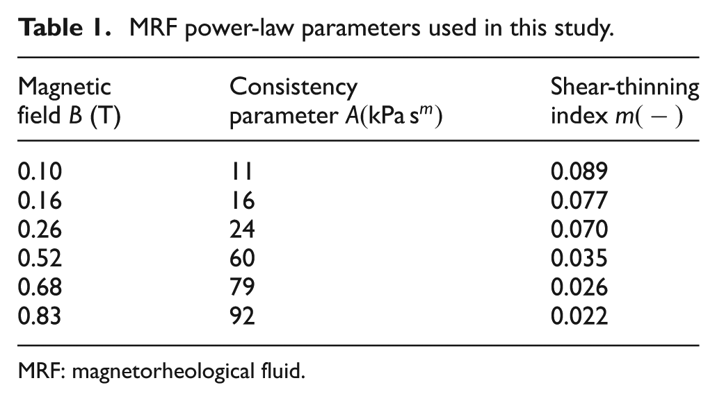
MRF: magnetorheological fluid.
Pure squeeze (+SAOS)
Figure 9 shows typical results from pure compression tests where MRF is submitted to a low magnetic field (0.17 T) and SAOS. As seen from the force curves, the highest compression speeds (1–5 mm/s) show similar rheological behavior, from which it is difficult to deduce significant information. As speed is reduced, however, a significant increase in force-to-gap relation appears. This suggests that filtration is occurring during compression at the slowest speeds (0.05–0.50 mm/s).
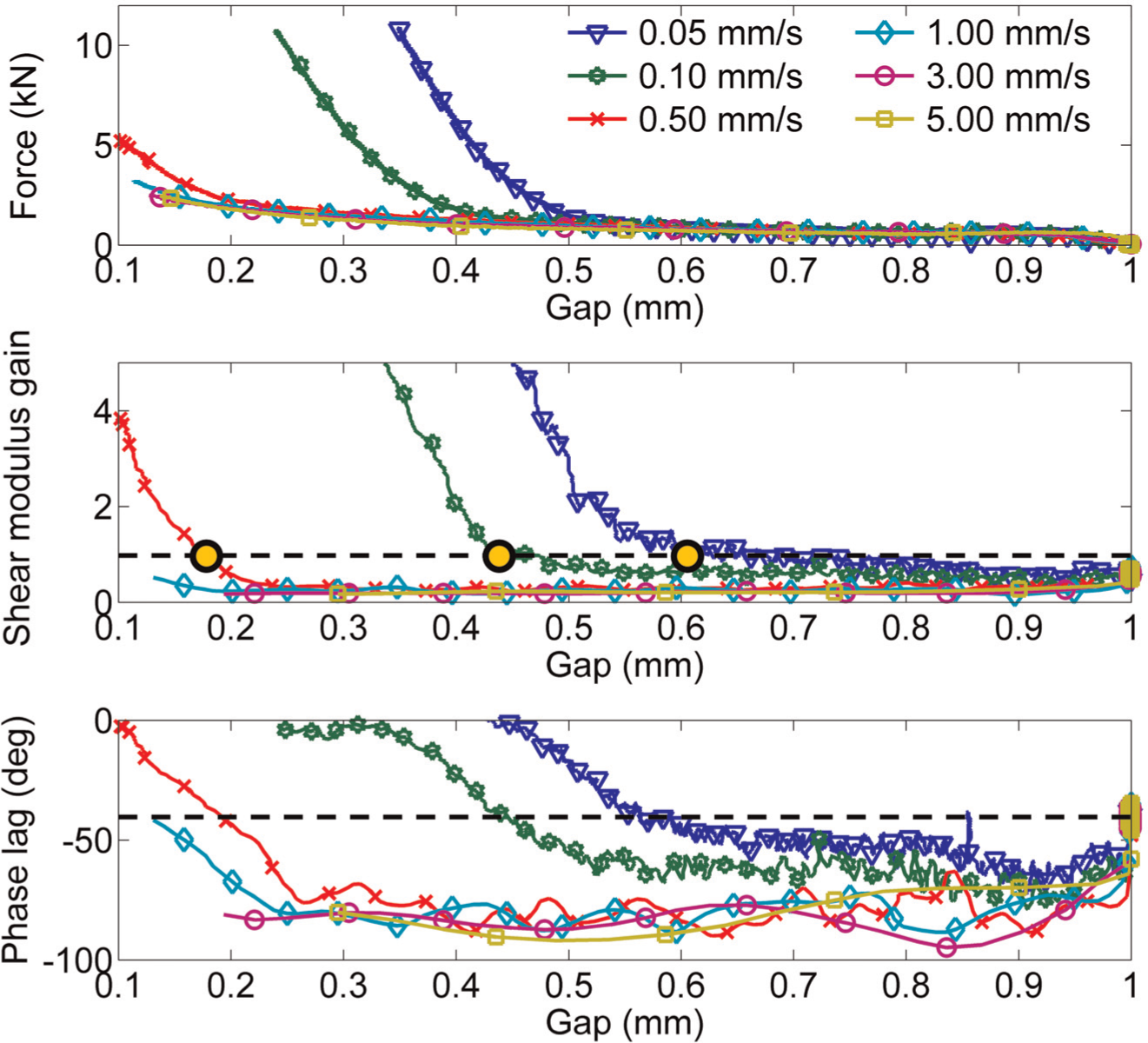
Influence of squeeze speed on the rheological behavior (force, shear modulus gain, and phase lag) of MRF under pure compression (0 r/min) and low magnetic field (0.17 T).
This behavior is further corroborated by the shear modulus (
In this study, the gap height (
For low magnetic fields, the evolution of the MRF shear modulus after transition is found to be similar for all tests, increasing strongly as gap is reduced. A gain of ∼5 is associated with a compression of 0.15 mm over the transition gap height where phase lag measurements show a strong elastic behavior (
As seen in Figure 10, higher magnetic fields (∼0.68 T) lead to similar behavior, but for higher compression speeds, due to a stronger particle structure (higher yield stress). One major difference is seen at very low compression speeds (<0.1 mm/s), where the force curves sharply decrease, shortly after compression begins. Further investigation indicates that this behavior might be induced by the MRF structure itself, as a force decrease occurs prior to linear actuator deviation from its course. As seen from the shear modulus and phase lag curves, this behavior occurs only when the MRF does not decrease during the initial compression phase. Under this condition, it is believed that the MRF is already in filtration regime as the test starts, thus forming an unstable microstructure that collapses under compression loads. This could be the origin of the decrease in the elastic and loss modulus seen by others (De Vicente et al., 2011), but this would require further investigation. Hence, in these particular cases, the transition gap heights are supposed superior to 1 mm for the purpose of this study.
Influence of squeeze speed on the rheological behavior (force, shear modulus gain, and phase lag) of MRF under pure compression (0 r/min) and high magnetic field (0.68 T).
At high magnetic field, the shear modulus appears to evolve differently after reaching the transition gap height
Squeeze-shear (+SAOS)
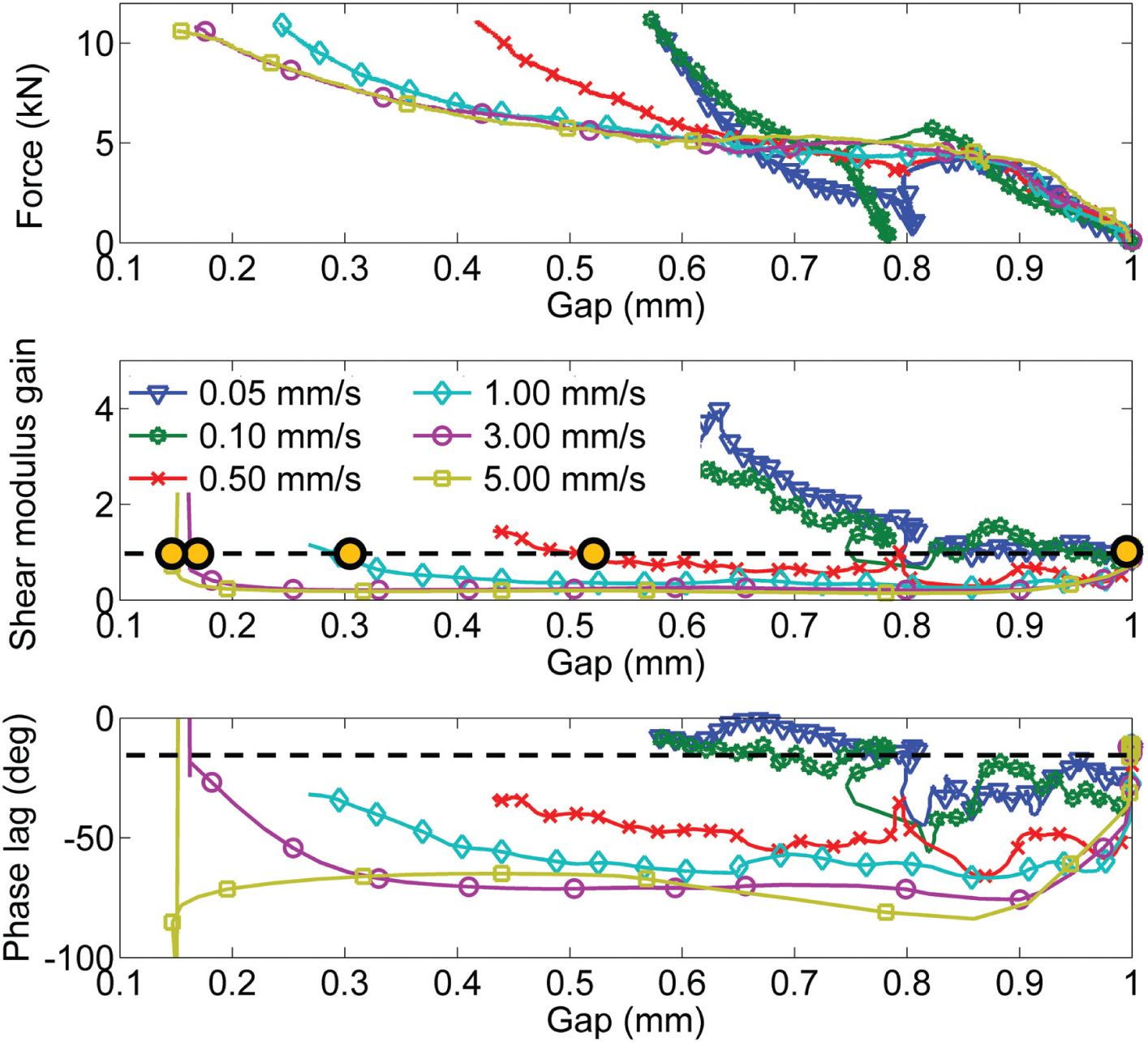
Typical results for the simultaneous squeeze-shear of MRF at low rotational speed (1 r/min) and high magnetic field (0.68 T) are shown in Figure 11. Although the super-imposed rotational speed is low (1 r/min), a significant difference is seen when compared with Figure 10 (0 r/min). While the force curves of Figure 10 show increasing force-to-gap relation as speed is reduced, the force curves from Figure 11 almost all collapse into a single curve down to ∼0.4 mm gap height.
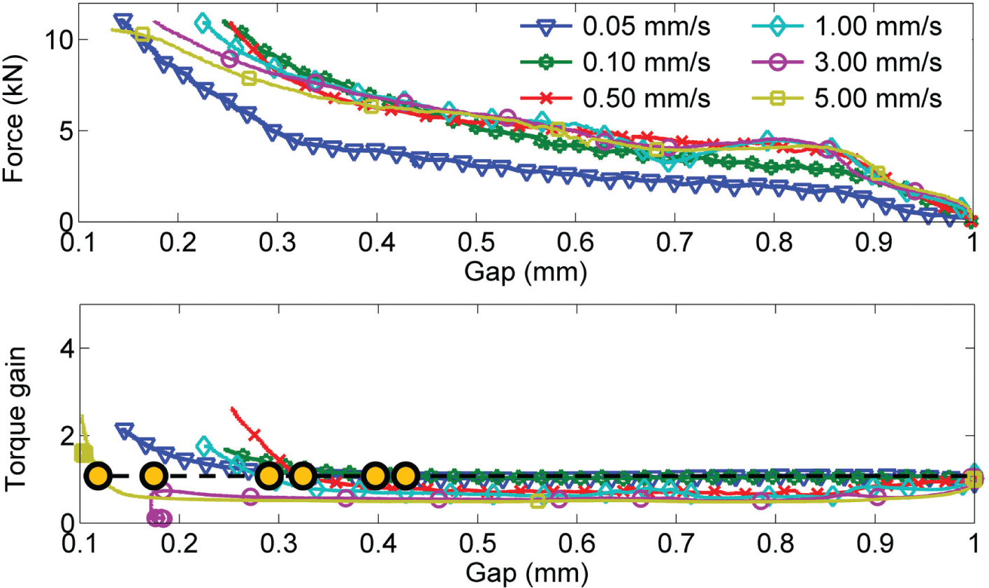
Influence of squeeze speed on the rheological behavior (force and torque gain) of MRF under simultaneous squeeze-shear (1 r/min) and high magnetic field (0.68 T).
Further comparing the force curves from Figures 10 and 11, the super-imposed rotation appears to have little effect on the force-to-gap relation at high compression speeds (e.g. 5 mm/s). At the slowest compression speeds (e.g. 0.05 mm/s), however, the force-to-gap relation is significantly reduced by the super-imposed rotation. This can be explained by the rheological behavior of yield-stress materials, which reduce their yield-stress resistance in the orthogonal direction to the main flow direction (Ovarlez et al., 2010). In Figure 11, high compression speeds and small gaps thus appear dominated by squeeze flow, while slow compression speeds and large gaps appear dominated by rotational flow.
As described in Figure 5, SAOS probes material viscosity when material is flowing. Thus, the rigidity gain and phase lag curves are not shown in Figure 11, since the MRF is constantly under shear (1 r/min). The torque gain curves, however, are used to measure the MRF yield stress. Comparing the torque gain curve of Figure 11 with the shear modulus gain curve of Figure 10, the transition gap heights appear very similar for the highest compression speeds (1–5 mm/s), yet different for slowest compression speeds, thus further corroborating said behavior of the MRF. The evolution of yield stress after transition is also found different for low compression speeds (0.05–0.5 mm/s), as the rotational shear rate appears to interfere with the structural reorganization.
Discussion
Pure squeeze (+SAOS)
From all the pure compression tests, the transition gap heights (
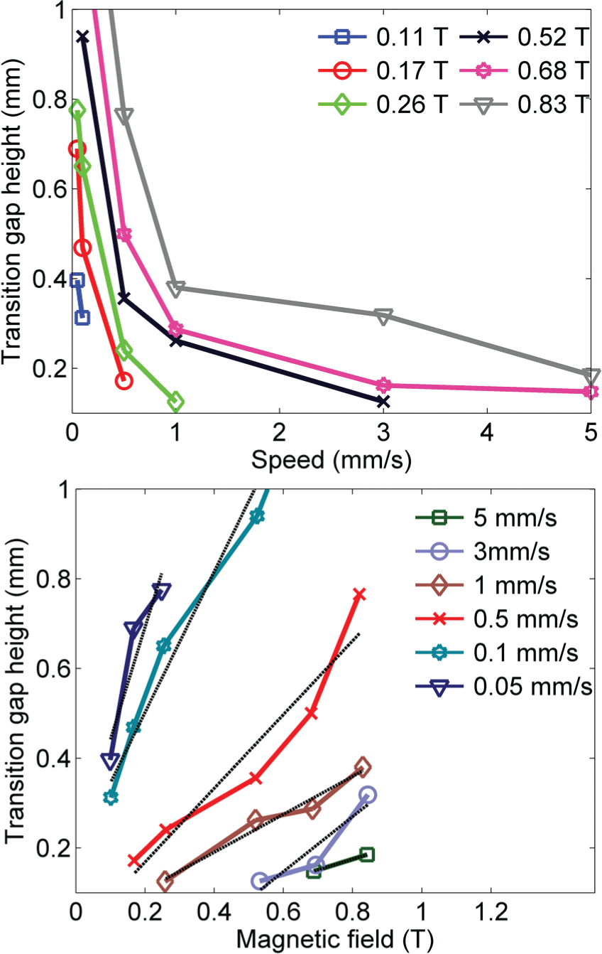
Experimental measurements of transition gap heights during compression tests, expressed as a function of speed (top) and magnetic field (bottom).
To compare the experimental results with the Péclet number, the transition gap heights calculated from equation (8) are traced in Figure 13. The liquid phase viscosity
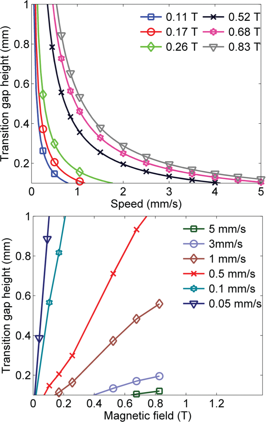
Theoretical predictions (Péclet number) of transition gap heights during compression tests, expressed as a function of speed (top) and magnetic field (bottom).
Considering that the Péclet number is derived from average (e.g. filtration velocity) fluid properties, Figure 13 (top) shows very good overall correlation with experimental results from Figure 12 (top), obtained with the parallel plate geometry. Further corroboration is found in Figure 12 (bottom) and Figure 13 (bottom), where the transition gap height shows a linear relation with the magnetic field. The deviation between experimental and theoretical results, seen mostly at slow compression speed, can be explained by several factors including the averaging of the fluid properties in the Péclet number or the approximation of the Darcy permeability
Altogether, the Péclet number predictions show very good correlation with experimental data. This suggests that the Péclet number can be used to describe MRF behavior during compression (e.g. Figure 9). Initially, when
Ultimately, the good correlation even suggests that the Péclet number could be used to predict the occurrence of super-strong behavior during the initial design phase of novel high torque-to-weight devices, or alternatively, for squeeze devices that must avoid the filtration phenomenon. Note, however, that the transition gap height predicted by equation (8) is derived from average fluid properties and thus might not yield accurate results for all geometries or in all conditions. Moreover, the evolution of MRF yield stress, following transition, still requires more investigation in order to predict accurate torque gains.
Simultaneous squeeze-shear (+ SAOS)
To understand the impact of rotation on the occurrence of super-strong, simultaneous squeeze-shear results are consolidated for comparison with pure compression behavior. Figure 14 shows the experimentally measured transition gap heights
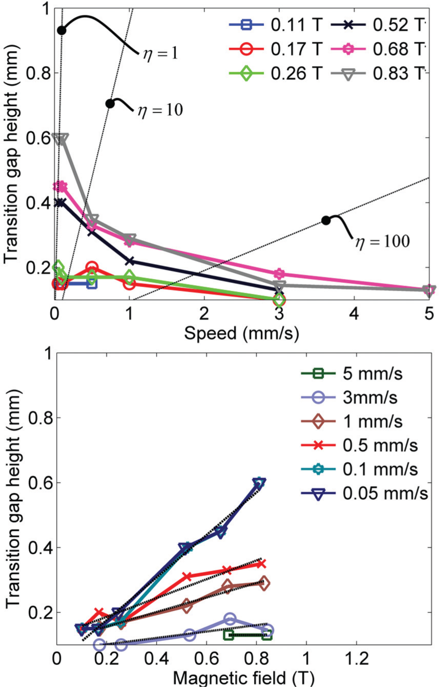
Experimental measurements of transition gap heights during compression tests with super-imposed rotation (1 r/min) expressed as a function of compression speed (top) and magnetic field strength (bottom).
Comparing Figure 14 (1 r/min) to Figure 12 (0 r/min), it can be seen that the super-imposed rotational speed has little impact on the transition gap heights measured at high compression speeds (>1 mm/s). However, super-imposed rotation has a significant impact at slow compression speeds, reducing transition gap height. To better understand this observation, squeeze rate (
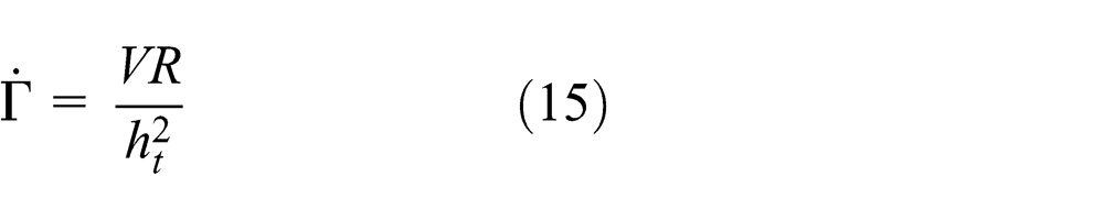
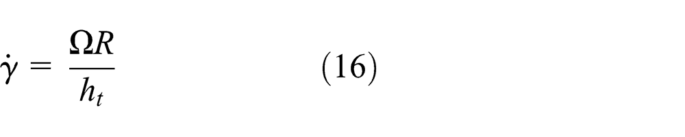
Using equations (15) and (16), the dominance (
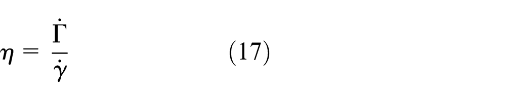
Dashed lines are then traced in Figure 14, representing a dominance ratio (
While this analysis relies on approximate shear and squeeze rates found at the exterior of the disk, note that a strong gradient exists toward the center of the plates, where shear and squeeze rates both tend toward zero. Further investigation is thus still required to fully understand the relationship between squeeze and shear, while their imposed rates are of the same order of magnitude. Future work could thus be devoted to study the impact of other squeeze interface geometries (e.g. annulus) which do not show such a strong gradient (in shear) toward the center of the plates.
Conclusion
In this study, the super-strong behavior of high-concentration MRF was experimentally investigated through a novel test bench that can simultaneously squeeze and shear MRF while monitoring yield-stress evolution with SAOS and torque measurements.
Experimental results obtained from pure compression tests, performed at different magnetic field strengths and compression speeds, show that the occurrence of super-strong behavior can be deduced from material parameters using the Péclet number. With the Péclet number, the compression of MRF can be described by three distinct phases:
Pe∼ 1: A transition occurs in the MRF behavior as the liquid phase is separated from the MRF particles. The MRF shear modulus and phase lag begin to increase.
The overall good correlation between experimental results and the Péclet number suggests the Péclet number can be used to guide initial design of super-strong MRF devices. With parallel plate disk-type geometry and high-concentration MRF, the super-strong behavior was demonstrated up to 5 mm/s, which is ∼100× faster compression speed than reported in previous studies.
Under simultaneous squeeze-shear, the phenomenon is also found governed by the Péclet number when the squeeze rate is dominant, that is, over 10× the rotational shear rate. The occurrence of super-strong, however, is greatly hindered when the shear rates and squeeze rates are of the same order of magnitude. This greatly limits the potential of the super-strong effect for commercial applications that generally operate at high rotational speeds.
Note, however, that further work should be devoted to better characterize the relationship (e.g. stress state) between squeeze and shear when their imposed rates are of the same order of magnitude. Further work should also be dedicated to understanding the impact of geometry on the occurrence of the super-strong effect as well as on the ability of the Péclet number to predict its occurrence. From a theoretical standpoint, the Péclet number could also be derived from another rheological model more widely used for MRF, as well as a Péclet number that incorporates shear-rate behavior to account for super-imposed rotation. Finally, the evolution of MRF yield stress, following a transition to filtration behavior, still requires more investigation in order to predict accurate torque gains from the super-strong behavior.
Footnotes
Acknowledgements
The authors would like to thank Marc Denninger for his help during the designing of the MRF clutch used in this study.
Declaration of conflicting interests
The authors declared no potential conflicts of interest with respect to the research, authorship, and/or publication of this article.
Funding
The authors would like to acknowledge the funding provided by the Fonds de recherche du Québec - Nature et technologies (FQRNT), the Natural Sciences and Engineering Research Council (NSERC), the Consortium de recherche et d’innovation en aérospatiale au Québec (CRIAQ), and the Mitacs internship program.