
Abstract
One of the challenges in the emerging field of origami engineering is achieving large deformations to enable significant shape transformations. Bistable compliant mechanisms provide a means to achieve this, and the goal of this research is to investigate the feasibility and design of a compliant bistable mechanism that is actuated by magneto active elastomer material. When exposed to an external field, magneto active elastomer material deforms to align embedded magnetic particles with the field. We investigate a case study using magneto active elastomer actuation through the development of finite element analysis models to predict the magnetic field required to snap the device from its first stable position to its second for various geometries and field strengths. The finite element analysis model also predicts the displacement of the mechanism as it moves from one position to the other to determine whether the device is in fact bistable. These results can be used to understand the relationship between the substrate properties and the bistability of the device. The experimental results validate the finite element analysis models and demonstrate the functionality of active magneto active elastomer materials to be used as actuators for such devices and applications of origami engineering.
Introduction
Bistable compliant mechanisms have the potential to be very useful in the emerging field of origami engineering. Such devices are useful in that no additional energy is required to hold the structure in the second stable position, as it is in a static equilibrium position. Another advantage of bistability is that the input actuation stroke or deflection can be smaller than would be required with a compliant mechanism that simply deforms elastically. The actuation input needs to move just enough to move the bistable mechanism from its first stable position to just beyond the unstable equilibrium configuration and it will naturally snap-through to the second stable position. In this article, we investigate the use of an active material to generate snap-through of a bistable compliant mechanism. This could be implemented as part of bistable origami structures, such as the waterbomb structure (Hanna et al., 2014). The waterbomb is bistable and can be actuated by applying a force to its center point. Several waterbomb structures could be used together to make more complicated structures or tessellations (Harnett and Kimmer, 2013).
To design a bistable mechanism for origami engineering using active materials, it is important to understand the parameters that make bistability possible. For this study, a bistable arch was developed using magneto active elastomer (MAE) patches bonded to a polydimethylsiloxane (PDMS) substrate. When the MAE material is exposed to an external magnetic field, the patches rotate to align the aggregate internal magnetization of the patch with the external field, generating torque that can be used to actuate the structure and move from one bistable position to the next. Finite element analysis (FEA) models are used to understand the relationship between design parameters such as the thickness and modulus of the substrate and the initial height of the arch to determine which of the designs are bistable.
Active materials in origami engineering
The use of origami principles in engineering has the potential to influence and transform active material structures. In the past few years, several groups have been working to advance this field. Some researchers have used origami modeling to decompose structures into simple geometric shapes and spherical mechanisms (Bowen et al., 2013a, 2013b) while others used simple geometric shapes and origami structures to assemble into something larger (Harnett and Kimmer, 2013). These larger structures have been integrated into devices and used to change shape or orientation when in use (Lee et al., 2013). Using active materials makes it possible to adapt these devices through the use of applied fields. For example, Nitinol wires (Peraza-Hernandez et al., 2013a, 2013b) in a mesh have been heated to create a variety of preprogrammed curved shapes from an initially flat sheet. Active materials actuated by fields ranging from thermal fields to magnetic fields have been investigated (Ahmed et al., 2013a, 2013b, 2014; Liu et al., 2012; McGough et al., 2014; Peraza-Hernandez et al., 2013a; Randall et al., 2011; Randhawa et al., 2011). Liu et al. (2012), for instance, used differences in light absorption to induce localized deformations in predetermined patterns. Ahmed et al. (2013a, 2013b, 2014) used dielectric elastomers to create bending and folding. In this article, magnetic fields are used to induce motion without physically touching the bistable arch device.
Bistability
A frequently used analogy for bistable devices is that of a ball on a hill, as shown in Figure 1. The ball begins at its first stable equilibrium position A, which is a local potential energy minimum, but when acted on by an external force, it moves up the hill toward an unstable equilibrium position B. If enough force is applied, the ball will move beyond position B to the second stable equilibrium position C, or minimum potential energy position, just like the snap-through of a bistable mechanism. This configuration constrains the motion of the ball between the two stable positions, like a bistable mechanism moves between its two stable positions (Jensen et al., 1999; Sonmez and Tutum, 2008).
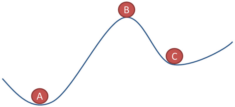
Ball on a hill analogy adapted from Sonmez and Tutum (2008). Positions A and C are stable; position B is unstable.
There are many advantages to using bistable devices. For example, bistable devices can achieve large deformations with relatively low input forces as they need only enough force to snap between positions. In the case of a bistable arch actuated by the MAE material, the MAE patches generate a torque when exposed to an external magnetic field as they try to rotate to align with the field. This torque is what generates the input needed to cause the device to snap. When the external magnetic field is removed, the bistable arch stays in the second position; however, it can be returned to the initial position by reversing the field direction.
Bistable compliant mechanisms
There are several types of bistable compliant mechanisms. These include latch-lock mechanisms, hinged multi-segment mechanisms, and residual-compressive-stress buckled beam mechanisms (Jin et al., 2004; Tsay et al., 2003). These devices have been designed as compliant mechanisms, which means that most, if not all, of the motion of the devices arise through the deflection of flexible segments (Masters and Howell, 2003). Bistable compliant mechanisms have two distinct stable equilibrium positions, and such devices can snap from one stable position to the other by storing and releasing energy during motion (Opdahl et al., 1998; Sonmez and Tutum, 2008). It has been reported that by combining these bistable mechanisms with a smart material actuator, actuation can be achieved with less power than electric motors (Cazottes et al., 2009). That is, power needs be applied only when the system is transitioning from one stable state to another. Many current methods of modeling bistable mechanisms used energy functions to determine the bistability of a device (Jensen et al., 1999; Jensen and Howell, 2004; Jin et al., 2004; Opdahl et al., 1998; Qiu et al., 2001; Sonmez and Tutum, 2008). When the potential energy function reaches a minimum, then the mechanism has reached a stable position. In the case of bistable devices, there are two local potential energy minima.
MAE material
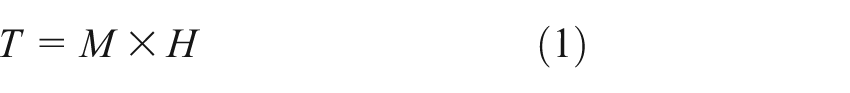
MAE materials have been used in a variety of applications such as car bumper design to maximize energy absorption in a collision (Bogdanov et al., 2009) and self-locomotion (Von Lockette and Sheridan, 2013). These elastomers have also been used to reduce noise vibration as part of a barrier system (Farshad and Le Roux, 2004). The mechanism investigated in this article is actuated with MAE material. The MAE material considered in this study is fabricated using 70% of the total volume Dow Corning HS II RTV silicone rubber compound, with 20:1 catalyst-to-compound ratio by weight, mixed with 30% of the total volume 325 mesh M-type barium hexaferrite (BaM) particles. This composite was selected as it is magnetically orthotropic. The orthotropic nature of the magnetization of barium hexaferrite provides useful anisotropy in the development of directional magnetic torque. The preferred axis provides a magnetic torque directly coupled to the cross product with the external field. Furthermore, the plate-like shape of the particles (Sheppard et al., 2006) accentuates the delivery of that torque to the matrix. By aligning particle magnetizations, and thereby particle orientations, during curing, the direction of the torque that results from interaction with the external field can be controlled. The resulting composite has an estimated density of ρ = 2800 g/cm3. The BaM materials used have a remanent magnetization of µ0M = 0.06 T (Ahmed et al., 2013a; Von Lockette, 2012; Von Lockette et al., 2009; Von Lockette and Lofland, 2011). Prior to the curing process, the BaM is uniformly mixed into the silicone rubber. Then a uniform constant field of 2 T is applied that aligns particles’ magnetizations prior to curing. Since magnetization axes of these plate-like particles are tied to particle geometry via plate orientation, the strong external field consequently aligns the particles themselves, ideally in a uniform direction, giving samples a magnetization ideally distributed about the direction of the external field. (Farshad and Benine, 2003; Sheppard et al., 2006; Von Lockette and Lofland, 2011; Von Lockette and Sheridan, 2013; Zhang and Budnick, 1997) The proposed design takes advantage of the magnetically aligned particles, orienting the MAE patches so that they rotate to align with the field applied in the experiment. While local gradients in the applied field will invariably produce some degree of magnetic forces, magnetic torque is the primary actuation that drives the actuation of the bistable device. The induced torque from an MAE patch can be determined from equation (1) where H is the applied magnetic field, M is the magnetization of the patch, and T is the resulting torque density
FEA model
An FEA model was developed using the multi-physics analysis program, COMSOL (2012), which is capable of coupling a structural model with an electromagnetic model, both of which are needed to model the bistable device actuated with MAE material.
The system was modeled in two dimensions following other works investigating MAEs that also perform two-dimensional (2D) FEA of three-dimensional (3D) structures (Bustamante et al., 2011; Raikher et al., 2008; Raikher and Stolbov, 2005; Von Lockette et al., 2011). For example, Bustamante et al. (2011) examined the response to combined magneto-mechanical loading of a block in simple shear, Raikher et al. (2008) and Raikher and Stolbov (2005) examined the bulging response to an external field of a ferrogel and an axisymmetric disk, respectively, and Sheridan et al. (2014) and Von Lockette and Sheridan (2013) examined the free and forced deformation of cantilever beam and multi-segmented accordion structures subject to an external field. The simulation results in Raikher et al. (2008), Sheridan et al. (2014), and Von Lockette and Sheridan (2013) were compared to the data with good agreement over wide deformation ranges.
The fundamental rationale driving the simulation geometry was that the primary actuations studied (displacements produced) were planar phenomena, for example, x–y only. The actuations arose from forces acting in the x–y plane and/or moments perpendicular to the plane that produces x–y deformation. Furthermore, the forces and moments acted on geometries that could be represented as 2D structures. The geometries studied were planar with cross sections uniform in the third dimension.
While it is understood that the magnetic fields produce 3D force fields, the fields were reasonably assumed symmetric with respect to out-of-plane (z-axis) actuation in the nominal case given symmetry of the geometry and the external field with respect to the z-dimension. The resulting net out-of-plane force was necessarily zero by symmetry. While it is also understood that the magnetic field varies with the z-dimension, the authors, and those referenced, choose to model the regions away from the edge effects at the extent of the boundary in the ±z-dimension. In essence, these types of analyses modeled the centerline behavior of the magnetic field interacting with the magneto active structure to produce actuation.
The model required two modules within COMSOL to accurately predict the motion of the device. The first was the solid mechanics model. This was used to set up the displacement boundary conditions of the substrate and the surface traction between the substrate and the MAE patches. The second module was the magnetic module, which was required to directly model the effect of an applied external field to the MAE patches and to calculate the resulting Maxwell surface stress (Farshad and Benine, 2003).
Figure 2 shows the initial shape, dimensions, and boundary conditions used for the COMSOL model. The model consists of a passive substrate with two patches of MAE material bonded to the substrate symmetrically about the centerline. The directions of the polarity of the MAE patches were selected so that when they are placed on either side of the centerline of the passive substrate, they apply equal and opposite torques to the substrate, resulting in symmetric deformation and snap-through.
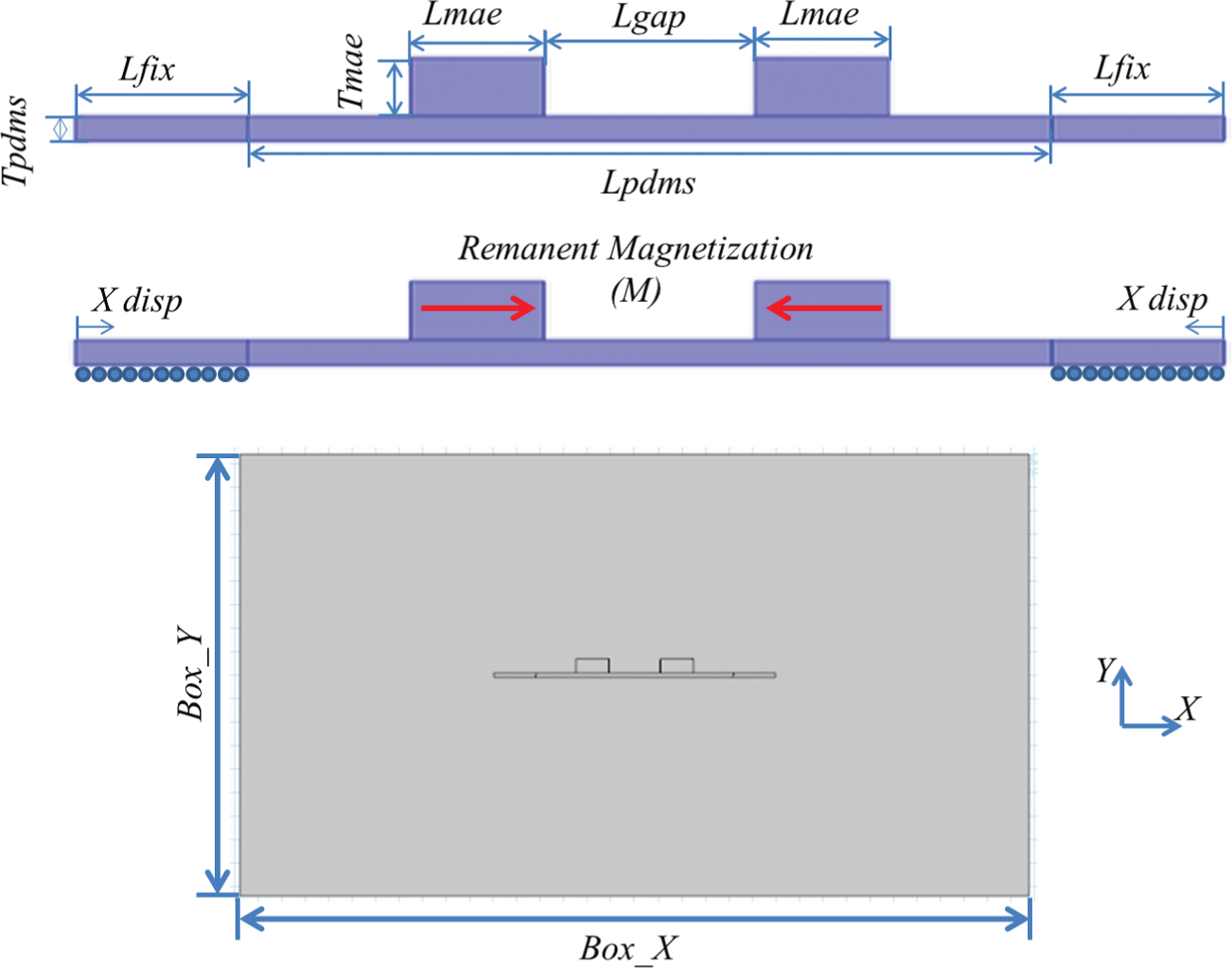
Initial shape, dimensions, and boundary conditions for air box in COMSOL.
The PDMS substrate is modeled as a hyper-elastic material using the Mooney–Rivlin two-term approximation (Kim et al., 2012). The C10 and C01 values were found empirically to be 63 and 31 kPa, respectively (Treloar, 1949). Viscoelastic and time-dependent magnetic effects are not expected to affect the snap-through field; therefore, the Mooney–Rivlin model is implemented in a quasi-static formulation. The MAE material is modeled through the Magnetic Field module built into COMSOL (2012). The magnetic forces and moments acting on the MAE patches are resolved into a boundary load acting on each of the MAE domains’ boundaries. The boundary load is calculated using the Maxwell surface stress tensor defined in the magnetics module. The magnetization
The magnetic field is created using an air box, as shown in Figure 2, which simulates the region between the two pole faces of a magnet. This is again developed using the Magnetic Field module in COMSOL. The top and bottom sections of the box, the opposing pole faces, are modeled as perfect magnetic conductors. The vector valued solution variable A is used to set the magnetic vector potential boundary conditions,
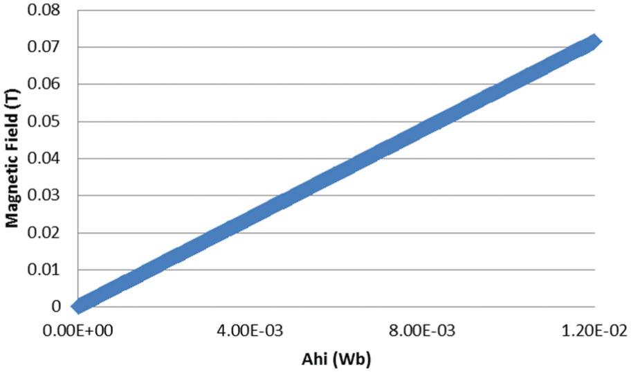
Relationship between Ahi and magnetic field.
Parameter values used for COMSOL model.

The finite element mesh of the PDMS substrate and MAE patched uses defined increments to divide the device into elements. To determine the number of elements in the mesh, each line length (e.g. Lfix, Lpdms) was divided by five. The air box was meshed automatically. The mesh ultimately consisted of 4732 2D nine-node triangular elements, and the model assumed a plane stress condition.
The model executes in three time-dependent steps. The first step uses only the solid mechanics part of the model, and the magnetic field is set to 0, as shown in Figure 4, Steps A and B. In Figure 4(b), the left and right ends are given prescribed displacements toward one another in the x-direction (referred to as the “initial displacement”), but they are fixed in the y-direction. Both ends are displaced horizontally to keep the mechanism centered in the air box used to create the magnetic field. Displacing the ends toward one another creates the initial shape of the arch. To ensure that the arch develops the initially curved shape, the initial displacement is incremented with time, while solving for the internal stress state before reaching the final position. Since this internal stress is an important part of the design and functionality of bistable devices, it is important to model the fabricated mechanisms from an initially flat position to ensure that the FEA models accounted for internal stress.
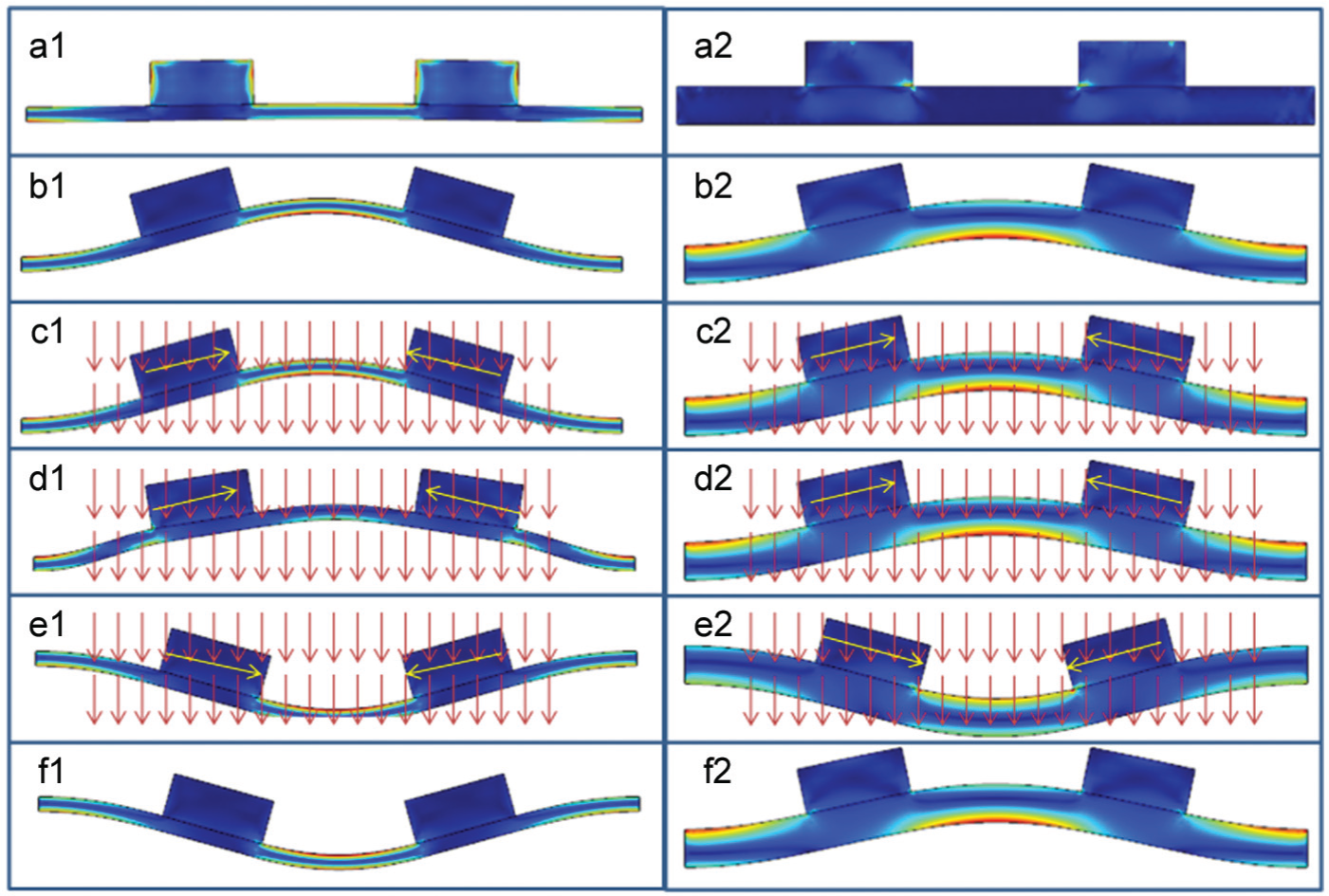
Steps used in the COMSOL model, 1 left is bistable and 2 right does not exhibit bistability: (a) initial shape, (b) initial stable arch shape, (c) initial application of the field, (d) displacement as the field is applied, (e) position after the snap, and (f) second stable position after the field is removed.
The second step of the analysis uses the final solution of the first step as its initial condition, as shown in Figure 4, Steps C through E. It takes the initially curved shape and applies a magnetic field that is again slowly incremented with time. The magnetic field is directed from the top to the bottom of the magnet, causing the MAE patches to rotate and inducing a torque. This torque slowly increases with the increasing field, eventually generating a moment large enough to cause the device to snap from its first stable position. Figure 5 shows the Maxwell surface stresses generated as the field is applied. This surface stress generates the effective torque of the MAE patches and ultimate snap-through of the device.
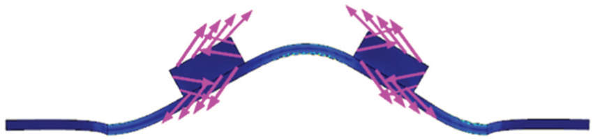
Maxwell surface stress on the boundaries of the MAE patches. Arrows show direction and relative magnitude of the Maxwell surface stress.
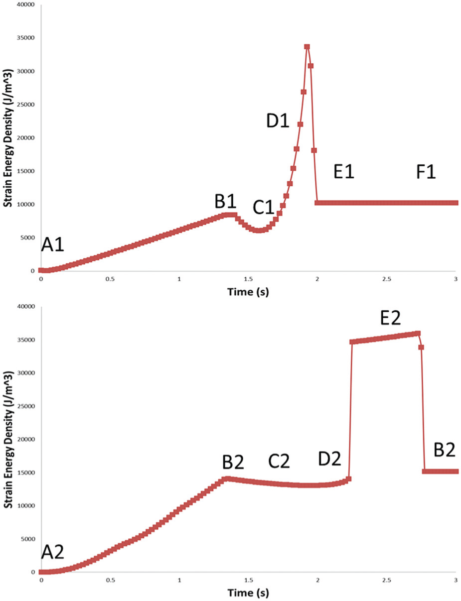
To determine whether the configuration of the device is bistable, the magnetic field is removed during the third step, as shown in Figure 4. If the device remains in the second position, then it is bistable. If it returns to the initial arch shape, then the device has snapped through but is not bistable. This is also shown by the strain energy density of the designs (see Figure 6). The strain energy density is computed by summing the element strain energy densities and dividing by the entire volume. When the device is bistable, the strain energy density drops to a local minimum, shown at point E1. However, if the device is not bistable, then there will not be a local minimum at the snap point, and the device will return to the first stable state when the field is removed, shown in E2 through B2. The design on the left in Figure 4 is bistable, whereas the design on the right snaps through but is not bistable. The strain energy densities for both cases are shown in Figure 6 and labeled corresponding to the steps in Figure 4.
Strain energy density of a bistable design (top) and design that does not exhibit bistability (bottom).
Figure 7 shows the y-displacement of the center point height of the bistable design as the magnetic field increases from the simulations. Once the magnetic field reached 0.069 T, then the MAE patch generated enough torque to cause the device to snap. This is shown by the instantaneous decrease in arch height as it snaps from the first position to its second. The relationship between the substrate properties and the bistability of the device is investigated in more detail in section “Parametric study.”
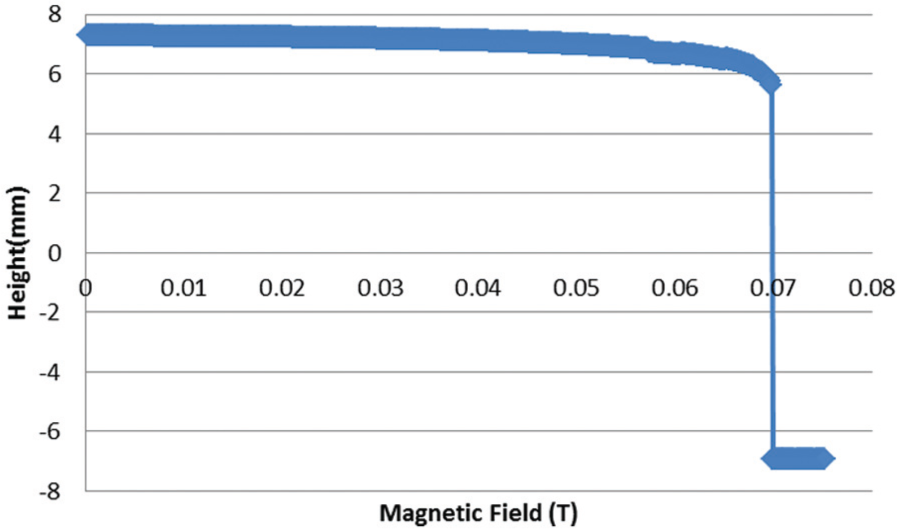
FEA prediction of center point displacement as the magnetic field increased.
Experimental validation
Experimental setup
An experimental test setup was developed to determine the validity of the FEA models using the dimensions of a design that is predicted by the FEA to be bistable (see Table 1). The PDMS strips were cut from a larger sample of the material with a thickness of 1 mm. The MAE patches were all cut from a long strip that was 5 mm wide. Three test samples were fabricated, and the ends were displaced toward one another and attached using PermaBond 268 to the rectangular acrylic bases so that the initial arch shape is achieved. The acrylic bases were laser cut with a 38-cm-long inner rectangular opening to ensure the proper initial height and displacement.
Prior to attachment to the acrylic base, the MAE patches were attached to the PDMS substrate using the same glue. The surface of the base and the PDMS substrate had to be sanded to ensure a good bond with the glue. These were mounted in place in the magnet using a wood stand, since wood is not magnetic. Figure 8 shows a schematic of the test fixture. The direct current (DC) regulated power supply, CSI3020X, had a voltage display which was calibrated to the magnetic field.
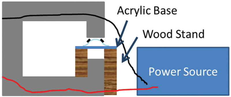
Test setup for experimental validation.
To generate the magnetic field, an electromagnet with an iron core and a 3.9 Ω resistance was used. The electromagnet was constructed in the shape of a “C” with two facing poles (also known as a c-magnet) and was powered by the DC CSI3020X power source. The magnetic field was measured using a LakeShore 475 DSP Gauss meter, and the relationship between the power supply voltage delivered and magnetic field produced between the pole faces was calibrated to yield magnetic field as a function of voltage, as shown in Figure 9. This relationship was used to calibrate the voltage values displayed during the experimental trials with magnetic field values.
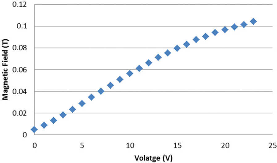
Magnetic field as the voltage increases.
For the experiment, each sample was placed in its initial arch shape on the wood stand. The wood stand was cut so that the samples would be level and centered vertically in the magnet. There were guidelines drawn on the top of the wood blocks to ensure that the samples were centered horizontally and into the plane, as shown in Figure 10. Slowly, the applied magnetic field was increased until the device snapped into its second stable position. Then, the field was removed to ensure that the device was bistable.
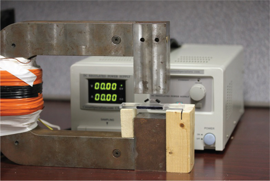
Experimental test setup with guidelines on the wood stand.
Each of the three samples, predicted by FEA described above to be bistable, did snap-through, and all of them were bistable, that is, they stayed in the snap-through position when the magnetic field was removed. Each test started at 0 T, and the magnetic field was slowly increased from there as it was in the model. A video of this was recorded using a Canon EOS 7D camera with a fixed focal length lenses. The camera recorded the shape of the arch as well as the voltage displayed by the power supplied. A ruler was placed near the arch and was used to find the height of the center point by analyzing the image using SolidWorks.
Figure 11 shows the three arches that were constructed for testing, and Figure 12 shows a screenshot of the information gathered from the camera. The height data were used to create a plot of the center point displacement as the mechanism moved from the first stable position to the second with the application of a magnetic field.
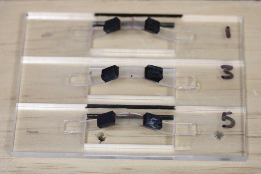
Three samples for experimental validation.
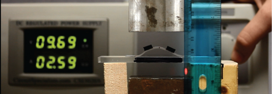
Image from the camera indicating the voltage and arch height.
Experimental results
Each sample was constructed and then tested five times to provide a data set of 15 runs. Between each run, the samples were manually reset to the initial arch shape. The five test run heights were then averaged to find the trend for each of the samples. The plot of the average center point heights for each fixture can be seen in Figure 13. The results from the FEA model can also be seen in this figure. As seen in the figure, little torque is generated by the MAE patches at low field strength, and there is little to no movement in the samples. All of them reached a point when the torque generated by the MAE patches caused the devices to snap-through just as it did in the FEA model. When the field was removed, the samples stayed in the second stable position. Standard error bars are shown, demonstrating that the results for each sample are repeatable. The snap-through magnetic field for the three samples ranged from 0.065 to 0.072 T. The initial arch height for the three samples ranged from 7.1 to 8.0 mm. This shows that there is some variation in the fabricated geometry for each device, specifically the initial displacement of the fixed ends. There is also a slight increase in the center arch height just before the samples reached the snap-through point. This could arise when the MAE patches are not perfectly symmetric, and one side pushes the other up slightly. This small asymmetry can be seen in Figure 14(b).
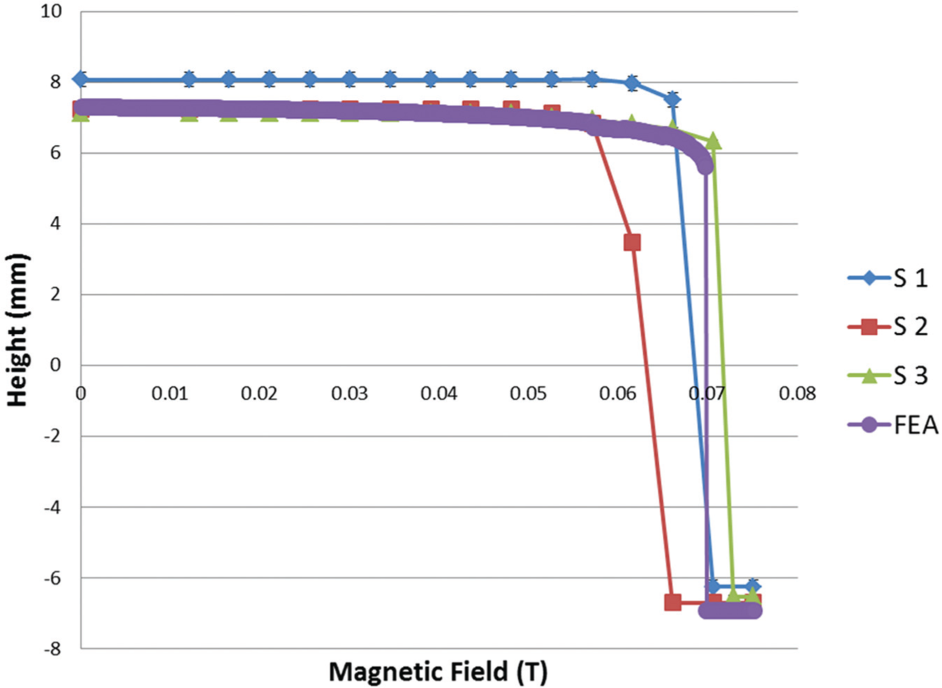
Center point height for the three test samples. The FEA model results are also shown.
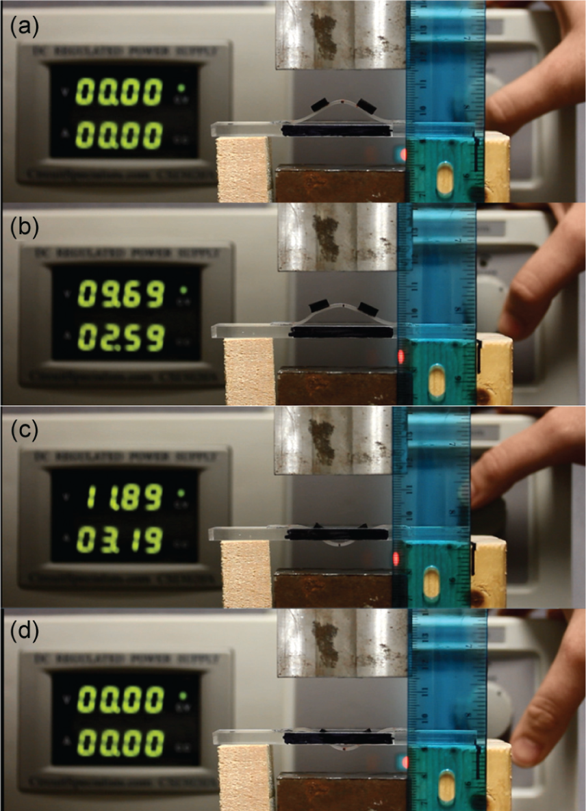
Stages of snap-through as the device is exposed to an increasing magnetic field. The power supply digital display in the left side of the image shows voltage (V), top, and current (A), bottom, which creates the magnetic field. Section (a) shows the device no applied field. Section (b) shows a low field. Section (c) shows a strong field. Section (d) shows the device after the magnetic field has been removed.
Figure 14 shows the motion of the first sample as it was exposed to the magnetic field. When there was no field or very little field (Figure 14(a)), then the device did not show any movement. As the field grew stronger (Figure 14(b)), the device began to elastically deform and ultimately snapped through to the second stable position (Figure 14(c)). When the magnetic field was turned off (Figure 14(d)), the device remained in the second position.
Discussion
There are several factors that may contribute to the differences between the FEA model and the experimental results. To begin, each of the experimental samples was constructed by hand. This could lead to imperfections in the size, shape, and initial displacement of the devices. We have found that very slight differences in the dimensions of the samples can lead to differences in the magnetic field required to get the devices to snap. It was also observed that the two sides of the arch do not move perfectly symmetrically as was predicted by the FEA (see Figure 14(b)). Because the imperfections are not accounted for in the FEA, it is to be expected that the FEA would predict only symmetric buckling. The unsymmetric buckling mode observed in the experiment has been demonstrated in the literature using an analytical model of curved-beam bistable mechanisms (Jin et al., 2004); the authors point out that this second mode would not be predicted by the FEA. As a consequence, the bistable compliant mechanism tested here may have a different snap-through point than predicted by the FEA model.
Another contributing factor could be the initial remanent magnetization (as well as the entire magnetization vs field response) of the MAE patches. If the magnetic particles are not evenly distributed throughout the larger sample during the curing process used to construct the patches, and aligned similarly in each patch, then there can be slight differences between the magnetization behavior of the patches. For this reason, it is important to determine a method to accurately measure this variation in the MAE material using x-ray diffraction and vibrating sample magnetometry. It is also possible that some particles may be able to rotate freely inside the silicone rubber, without contributing to the overall torque. This results in a lower remanent magnetization than expected.
Improving fabrication techniques is an important focus area. Two key areas, uniformity of composition and accuracy of material placement in the composite structure, have been determined most important. Uniformity of composition is being addressed through examination of various surfactants to produce uniform particle dispersion in the as-mixed state, which is believed will aid subsequent alignment in the presence of a magnetic field during curing. Preliminary studies underway utilizing x-ray diffraction techniques and rotating sample magnetometry suggest dispersion and alignment in the materials cured in a field are dependent on process variables. This remains an area of ongoing investigation for the authors.
Parametric study
Setup of parametric study
From a design point of view, it is important to understand the way various parameters in the model affect the magnetic field required to get the bistable arch to snap and the bistability of the device. To investigate this, several parameters were varied using the FEA model: PDMS substrate thickness (TPDMS), initial displacement (Xdisp), MAE length (LMAE), and the length of the gap between the MAE patches (Lgap). The values for the parameters can be found in Table 2. All combinations of these variables were used to generate a total of 225 designs. The initial and final arch heights were recorded to find the total displacement of the arch along with the magnetic field at snap-through, as well as the maximum von Mises stress experienced by the substrate. The bistability of the design was also noted based on the strain energy density minima using the technique discussed in the FEA section. The results from this study were analyzed using a trade space visualization tool developed by the Applied Research Lab (ARL) at Penn State University to give users the ability to intuitively visualize multi-dimensional trade spaces and derive relationships between design parameters (Stump et al., 2004).
Parametric sweep values.
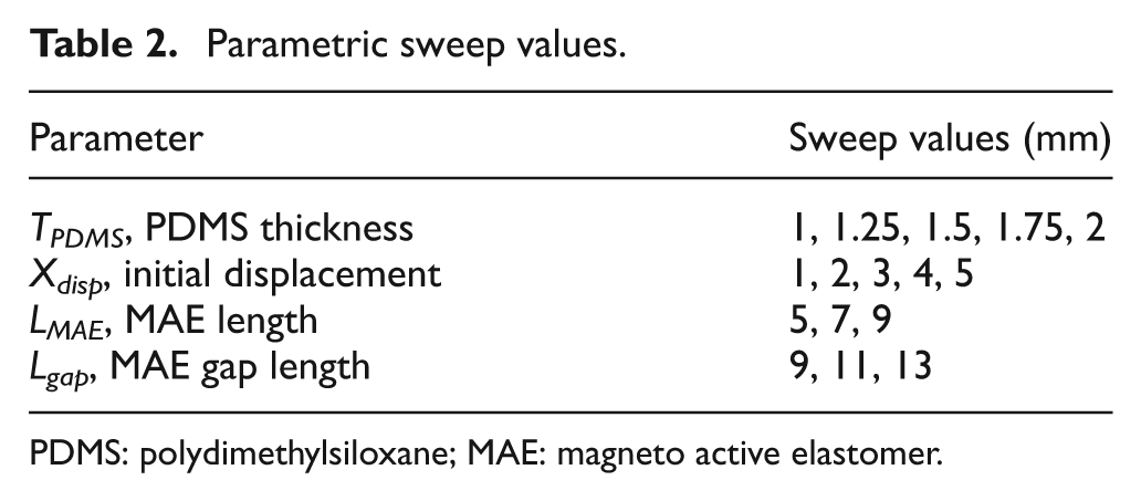
PDMS: polydimethylsiloxane; MAE: magneto active elastomer.
Parametric study results
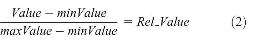
The results of the parametric study revealed many design implications. The initial displacement, PDMS thickness, magnetic field, von Mises stress, MAE separation, and MAE length were normalized with respect to the maximum (maxValue) and minimum (minValue) values of the variable shown in equation (2)
The parametric study revealed a relationship between the thickness of the PDMS substrate and the magnetic field required to cause snap-through. As the design became thicker, the magnetic field required for snap-through increased. There is also a relationship between the initial displacement of the device and the magnetic field. Again, as the initial displacement, corresponding to arch height, increased, the magnetic field required increased. These relationships can be seen in the glyph plot in Figure 15. The figure also shows that the bistability of the device is also strongly dependent on the thickness and initial displacement of the PDMS substrate. As the substrate designs got thicker and the initial displacement became smaller, the designs tended to not be bistable as shown in Figure 15. While the designs that do not exhibit bistability did not stay in the second position, the magnetic patches did generate the torque required to snap the designs to a second position.
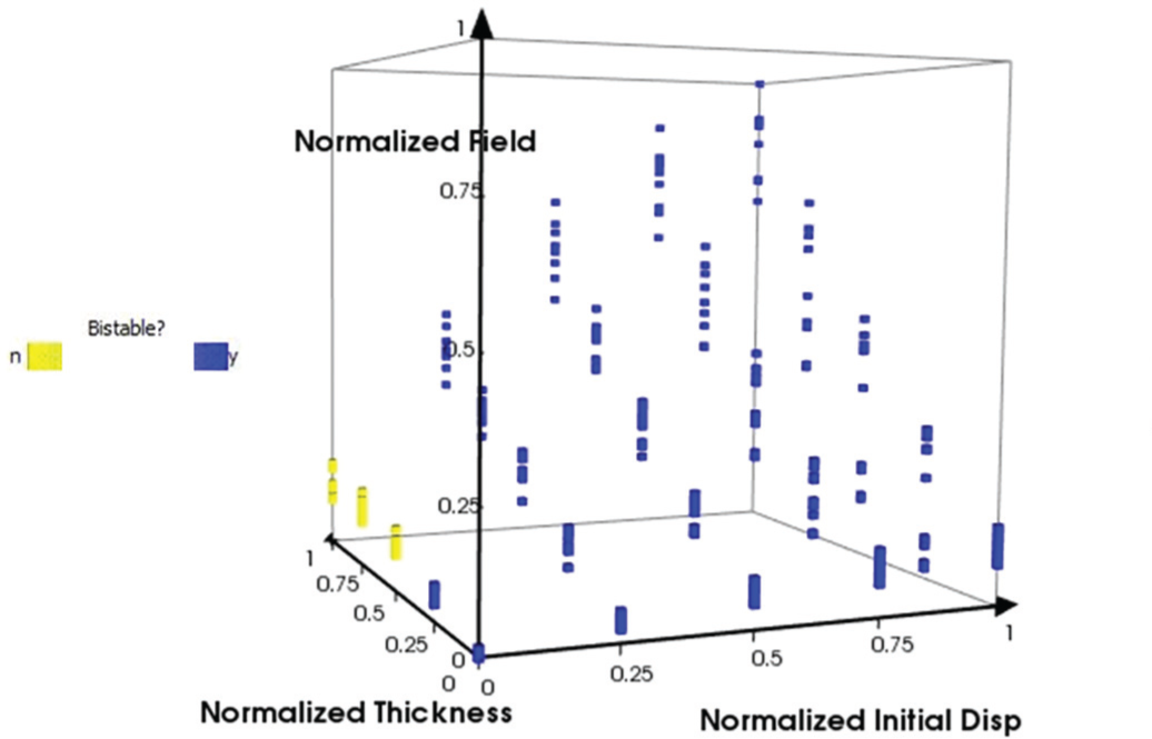
A glyph plot of the relationship between the thickness and initial displacement of the PDMS substrate and the magnetic field required to cause snap-through of the device design.
Varying the location and length of the MAE patches did not prevent snap-through for the range studied. The magnetic fields required for snap-through do change, but snap-through is not prevented. Figure 16 shows a glyph plot of the normalized thickness and displacement with varying MAE patch sizes to represent the different lengths of MAE patches simulated. The variables plotted on the x-, y-, and z-axes are the same as in Figure 15, but the size of each glyph (i.e. each cube) indicates the length of the MAE patch—the larger the glyph, the larger the patch. In general, as the MAE patch length is increased, a smaller magnetic field was needed to actuate the device; however, snap-through is still driven primarily by thickness and initial displacement since the area in the glyph that is not bistable remains the same.
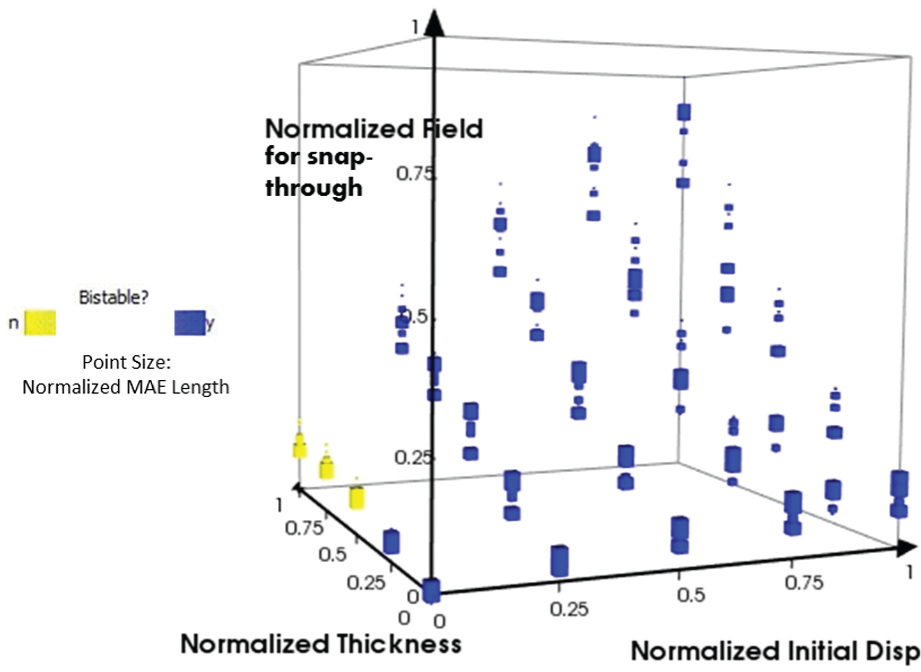
A glyph plot showing the normalized MAE length variation and its effect on the magnetic field required for snap-through. Size of the glyph indicates the relative length of the MAE patch.
We observed more variation in the separation between the MAE patches and the field required to actuate the device, which is plotted in Figure 17. Figure 17 shows a glyph plot of the normalized thickness, initial displacement, and field strength as before, but now the glyph size represents the different separations of MAE patches. The larger the glyph (i.e. the cube), the greater the sepration (Lgap) between the patches. In some cases, as patch separation decreased, a lower field strength is required to cause snap-through; however, this was not always the case as thickness and initial displacement again drive bistability. By studying these variations in different parameters across Figures 15 to 17, we conclude that thickness and initial displacement are the main drivers of bistability in this mechanism, not MAE patch sizes or their placement on the mechanism. The next section investigates this finding in more detail.
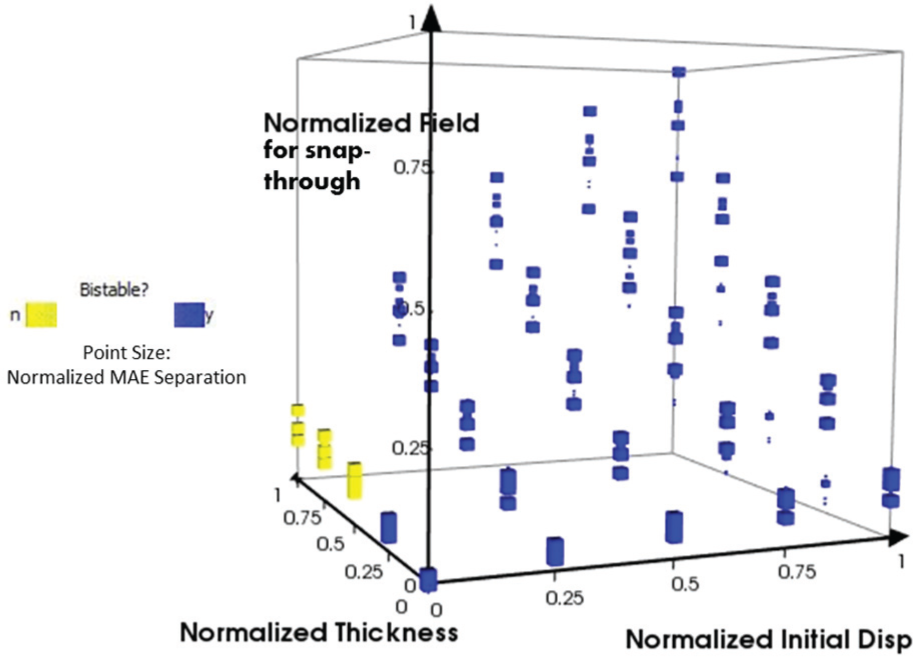
A glyph plot showing the normalized MAE separation variation and its effect on the magnetic field required for snap-through. Size of the glyph indicates the normalized distance between MAE patches.
Bistable region
Additional simulations were performed to refine the region of bistability. This region can be seen in Figure 18. As stated previously, designs that have greater thickness with a lower initial displacement tended to not be bistable. For this particular substrate design, with 5 mm width and 42 mm length, the region of bistability occurs when the initial displacement is around 75% of the PDMS thickness. As the designs are displaced, the strain energy density in the design increases linearly. This could lead to the linear trend seen from these sweeps.
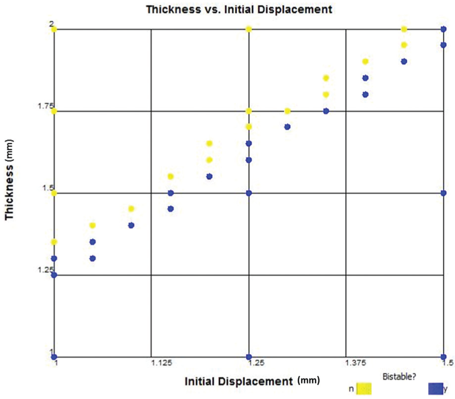
Bistable region for the PDMS substrate design.
These results indicate that using a thinner substrate leads to lower required actuation field. This has limits, however, as using a substrate that is too thin may not be able to support the weight of the MAE patches. Using larger MAE patches can also reduce the required field with the tradeoff of using more material, making the devices weigh more and be more expensive to manufacture. More studies are needed to understand the ideal locations of the patches and to select the ideal MAE patch size for a specific arch height. If only a small movement of the arch is required for the design, then it is important to use a design that has a low arch height, yet remains bistable. The force generated by the arch throughout its motion is important to understand. Designs with thicker substrates and greater initial displacements require more torque to actuate but also exert more force. This information helps designers select the appropriate thickness and initial displacement to achieve specific design goals.
Extension to origami engineering: an MAE-actuated waterbomb
There are many examples of bistable structures in traditional origami. For example, the waterbomb is bistable and can be actuated using a force applied to the center point or by active materials such as MAE. The use of several waterbomb structures could be used to make more complicated structures (Harnett and Kimmer, 2013). An example of the waterbomb structure can be seen in Figure 19, where MAE patches have been bonded to a creased paper substrate. The structure begins in one stable position, and when a magnetic field is applied, the torque generated by the four MAE patches causes snap-through to the second stable position. When the magnetic field is removed, the waterbomb remains in the second stable position. The process can then be reversed by reversing the direction of the magnetic field. The bistable arch developed in this article is similar in nature to the waterbomb structure. Bowen et al. (2015) developed a dynamic model of the waterbomb to better quantify and design the placement and alignment of the MAE patches to activate bistable behavior.
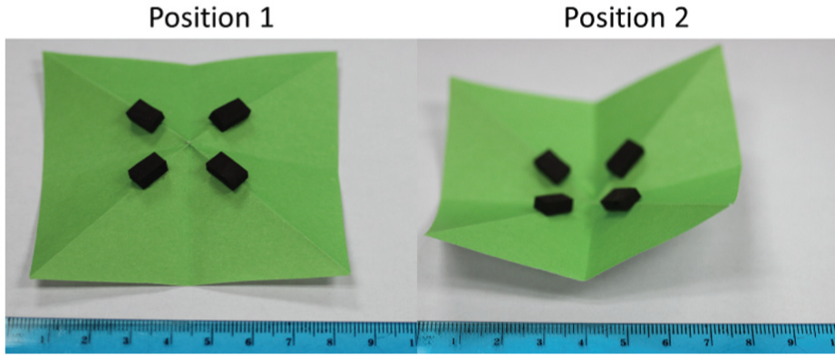
Bistable origami waterbomb base actuated by MAE patches.
Closing remarks and future work
Achieving large deformations through the use of bistable devices has been demonstrated with the use of active materials. The modeling and experimental work in this article has the potential to advance the field of origami engineering. An FEA model was developed to be able to predict the bistability of an arch design and determine the magnetic field required to get the device to snap from its first to second stable position. The experimental results validated this model and illustrated the importance of precisely developing the devices. A parametric study of several design parameters showed the relationship between the substrate thickness, initial displacement, bistability, and magnetic field required to actuate the device. Future work is required to design and formally optimize the model to maximize the height of the center point while minimizing the magnetic field required to achieve snap-through of the device. In addition, this work, developing composites with embedded MAE patches (Von Lockette, 2014), will provide symmetric structures, in contrast to top affixed patches producing asymmetry, from which more generalizable conclusions about bidirectional bistability may be drawn. These devices could be used as a switch to toggle a device without the need for mechanical manipulation. Instead, applying a field around the device can cause the switch to move from one position to the other. It is important to perfect the fabrication technique to improve the design of the mechanisms to ensure that the predicted field is sufficient to actuate the device. It is also important to better understand the behavior of the BaM particles and how they interact with the silicone rubber when a magnetic field is applied. To address fabrication issues, the authors are investigating additive manufacturing techniques to improve repeatability in device construction, to lessen material placement defects and decrease variability in composite preparation. Preliminary results show the ability to align magnetic particles as they flow through the deposition system and to retain alignment during curing (Bilyk, 2014; Sheridan et al., 2014; Von Lockette and Sheridan, 2013). This remains an area of ongoing investigation. To better understand particle–field interactions, the authors have begun probing the dispersion and physical/magnetic alignments of particles using rotating sample magnetometry as well as x-ray diffraction studies.
Footnotes
Appendix 1
Acknowledgements
The authors thank Saad Ahmed for casting the PDMS used in the experiments.
Declaration of Conflicting Interests
The author(s) declared no potential conflicts of interest with respect to the research, authorship, and/or publication of this article.
Funding
The author(s) disclosed receipt of the following financial support for the research, authorship, and/or publication of this article: We gratefully acknowledge the support of the National Science Foundation EFRI grant number 1240459 and the Air Force Office of Scientific Research. Any opinions, findings, and conclusions or recommendations expressed in this material are those of the authors and do not necessarily reflect the views of the National Science Foundation.