
Abstract
In this article, energy harvesting from a beam with traveling mass is studied. Harvesting was carried out by attaching a thin piezoelectric patch directly on the beam. A theoretical formulation was presented for the problem of energy harvesting from moving mass on a simply supported beam. To validate the results, an experimental setup was designed and fabricated to measure the beam response and voltage induced in the piezoelectric patch during the mass traveling on the beam. The results indicate that the analytical and experimental values for the beam midpoint deflection and the piezoelectric voltage are in good agreement. Finally, the effect of resistive load on the harvested power was considered and the optimum resistive load for maximizing the power was calculated.
Introduction
Nowadays, with upcoming energy issues, one of the most challenging areas of research is energy harvesting from structures. One way for harvesting electrical energy from oscillating structures is using piezoelectric materials. Many structures can be targeted for this purpose; however, harvesting energy from bridges or railways is one of the promising. The energy acquired from this method can be used for supplying bridge condition monitoring sensors (Ng and Liao, 2005) or transferring power in form of wireless waves for any other uses (Ottman et al., 2002). Considering cars and trains passing through bridges causing the bridge to vibrate, finding the dynamic response of the bridge under moving mass is essential for maximizing gained power.
Once a beam is exposed to a moving load, the stresses which are developed in the beam are much higher than the time that loads are static. This can cause high enough strains in the bridge, which is why the bridges or railways are the most suitable structures for energy harvesting by piezoelectric materials. Investigating the response of beam under moving load or moving mass had been a field of study during history (Ouyang, 2011). Ting et al. (1974) developed a general algorithm to solve the dynamic response of an elastic beam under moving mass. Foda and Abduljabbar (1998) studied the influence of the parameters of a system on the dynamic response of the single-span beam subjected to a moving mass using dynamic Green function formulation. Lin and Trethewey (1990) introduced a finite element method for gaining the dynamic response of a simply supported beam under moving dynamic loads. Michaltsos et al. (1996) solved the problem of moving load and moving mass simultaneously on a simply supported beam and compared the results. Results of Michaltsos effort show that while the moving mass is small enough compared to the beam’s mass, the response of the beam under moving mass is not far from beam response to moving load. Stancioiu et al. (2011) studied the moving mass problem experimentally for a multi-span flexible structure. Also Fryba (1999) has made a comprehensive study on various kinds of beam and plate vibration problems due to moving loads.
Piezoelectric energy harvesting technologies have become prominent field of study due to increasing interest in running low-powered electronics especially for wireless applications (Priya and Inman, 2009). The amount of gained power and different ways to maximize the harvested energy from structural vibration have resulted in an explosion of academic studies in this field during last decades (Liao and Sodano, 2008; Shu and Lien, 2006).
There are two approaches in harvesting energy from bridges under moving loads; first with a cantilever beam which the piezoelectric patch is installed on it while the cantilever first natural frequency matches the bridge main natural frequency. The other approach is attaching a thin piezoelectric patch directly on the bridge (Erturk and Inman, 2011). Erturk (2011) theoretically formulated the problem of energy harvesting from moving load on a simply supported beam with both approaches. Ali et al. (2011) solved the energy harvesting problem for the first approach with numerical example without any experimental validation.
In this study, first, theoretical formulation was presented for energy harvesting from moving mass on a simply supported beam and then the beam response and piezoelectric patch voltage were obtained for different moving mass velocities. Next, an experimental setup was designed and constructed to measure the beam midpoint deflection during the moving mass traveling on the beam. Afterward, by installing a piezoelectric patch on the beam surface, the open-circuit voltage of as a result of beam vibration under moving mass is measured experimentally and has been compared with the theoretically calculated values. Finally, the effect of electrical circuit resistive load on the harvested power has been investigated and the optimum resistive load for maximizing the power has been evaluated.
Theoretical approach
The schematic model of a beam traversed by a moving mass is shown in Figure 1.
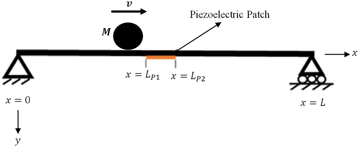
Schematic of moving mass problem.
In Figure 1, L is length of the beam and mass M is moving along the beam with constant velocity v. Moreover, there is a piezoelectric patch covering the region
The governing differential equation of beam traversed by a moving mass can be expressed by equation (1)
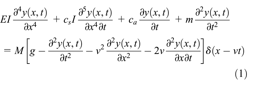
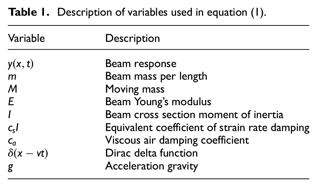
The description of variables used in equation (1) can be seen in Table 1.
Description of variables used in equation (1).
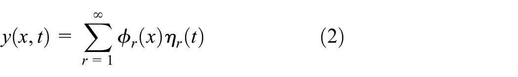
Therefore, response of the beam can be expressed as
Here,
where
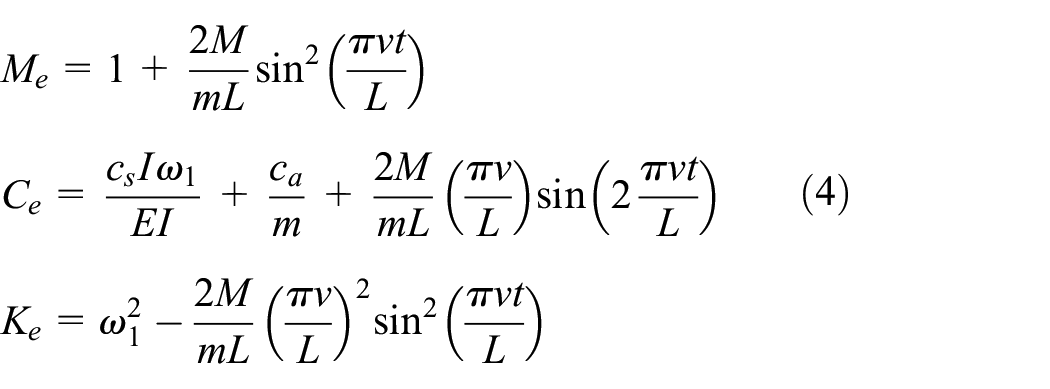
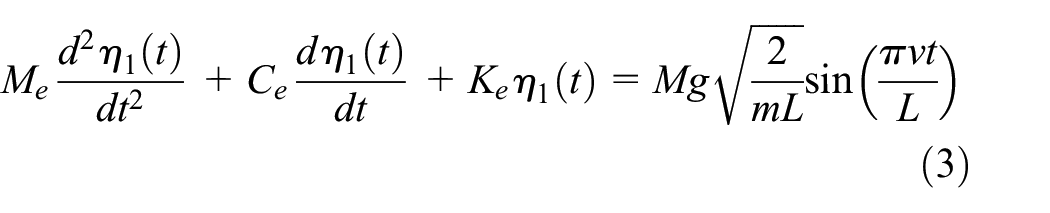
where
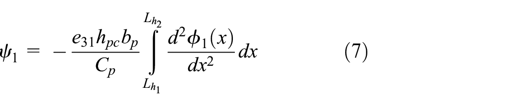
The approximate response of the beam under moving mass can be found by solving equation (3). The obtained voltage from piezoelectric patch across the resistive load can be described by equation (5) (Erturk and Inman, 2011)
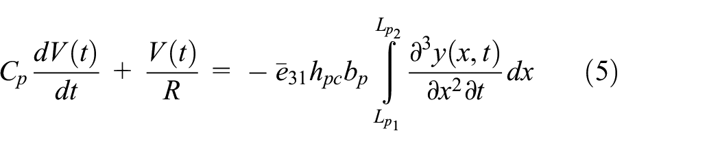
where
Substituting the beam’s response into equation (5) gives
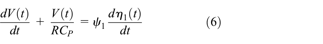
where
Equations (5) and (6) should be solved to obtain the piezoelectric patch voltage. We have used a numerical solution to the problem. Therefore, the system is transferred to some first-order differential equations and the numerical solution of system state variables is obtained in the time domain. The state variables for the first vibration mode are considered as
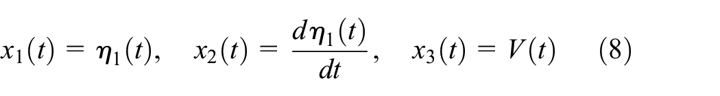
where
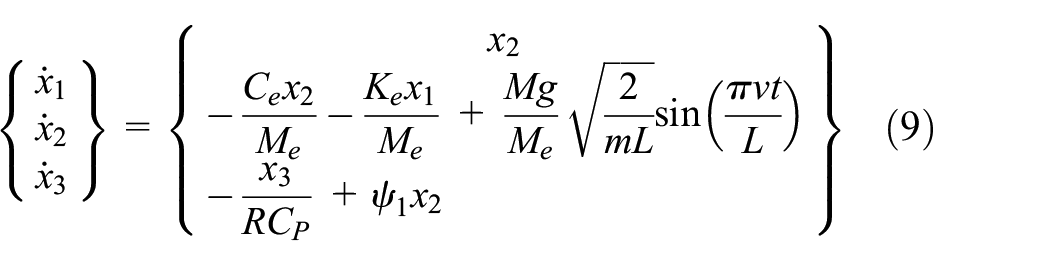
It is notable that three initial conditions are assumed to be zero in the simulations. The set of ordinary differential equations (9) are solved using ode45 algorithm in MATLAB software. The time history of beam displacement and the voltage output is obtained for various moving loads with different speeds.
Experimental setup
In this article, theoretical results have been validated by the experimental tests performed by bridge energy harvesting simulator device (Figure 2). This device is used for simulating small-scale bridges; hence, length of the beam used in this device can be varied between 550 and 1050 mm. The width of the beam was 70 mm due to the base and supports dimensions.
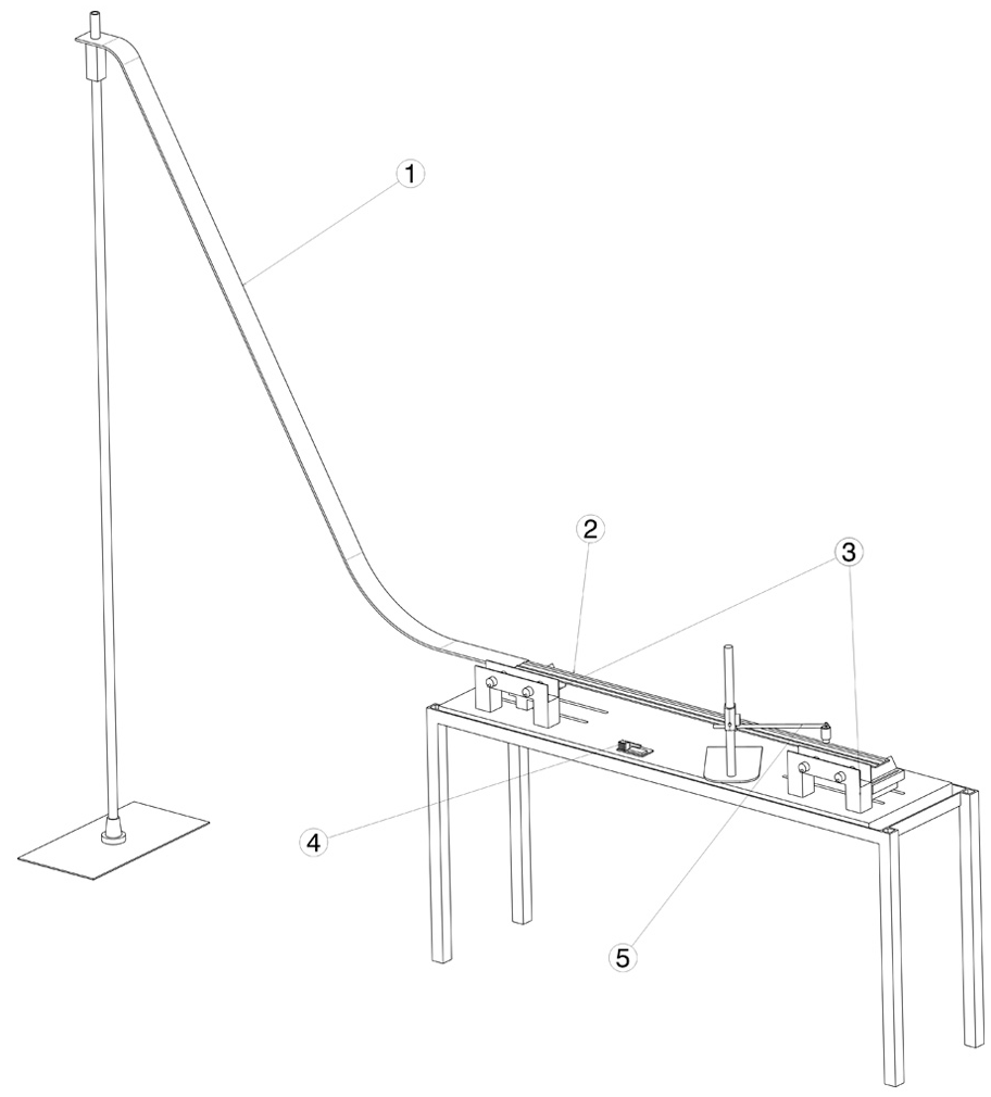
Schematic of designed device for experimental evaluation—1: ramp; 2: beam; 3: light sensors; 4: microcontroller; and 5: analog proximity sensor.
The spherical moving mass accelerates by being released from a specified height on the ramp and moves along the beam with approximately constant speed due to low frictional force between the beam and the moving mass. Mass speed is measured in the beginning and the end of the beam using two sets of light sensors. The average speed can be displayed from the screen of a microcontroller board which measures the spent time between every set of sensors. Two sets of light sensors are used in this device in order to check the constancy of mass speed along the beam. The moving mass weights are 0.33 and 0.64 N which cause the beam maximum static deflection to be, respectively, 0.28 and 0.55 mm. Figure 3 displays experimental setup used in this article.
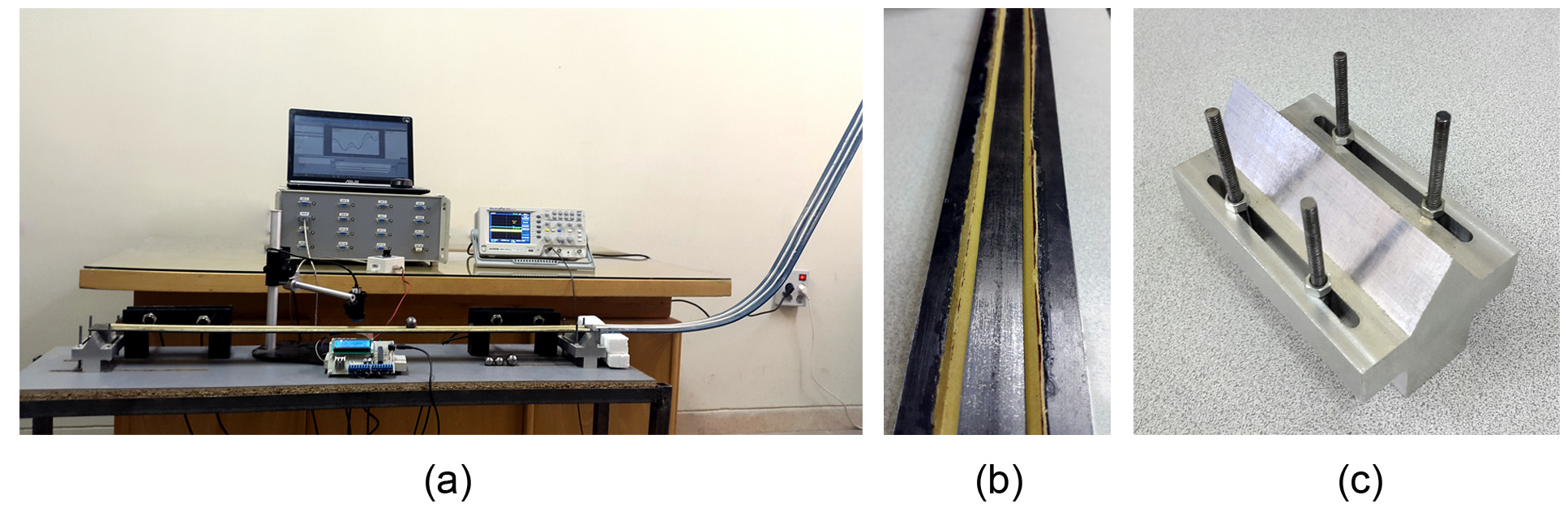
(a) Experimental setup and related devices, (b) rail, and (c) support.
The selected beam used for performing experimental tests with dimensions 1000 mm × 50 mm × 3 mm is made of steel; a rail has been located on the beam to prevent the moving mass from falling off the beam. The rail is made of two triangular prisms with dimension of 2 mm × 2 mm × 1000 mm made of wood in order not to affect the beam stiffness. The three-point-bending experiment for calculating Young’s modulus of the beam had been carried out after the rail was attached to the beam in order to include the rail stiffness effect on the bridge stiffness. Evaluated Young’s modulus of the beam is 215 GPa. The moment of inertia of the rail is neglected in the theoretical analysis. Also the calculated critical speed for the beam is 63.85 m/s which is much higher than the experiment speeds in order to avoid any form of resonance.
The piezoelectric patch which is attached on the beam is a MIDE QP20N model installed on the beam midpoint for maximizing the strains and so the piezoelectric output voltage. Data acquisition processes for experimental tests can be seen in Figure 4. By mass moving along the bridge, its midpoint displacement is acquired using an analog displacement proximity sensor. The signal from this sensor goes directly into an oscilloscope and afterward gets processed on a computer.
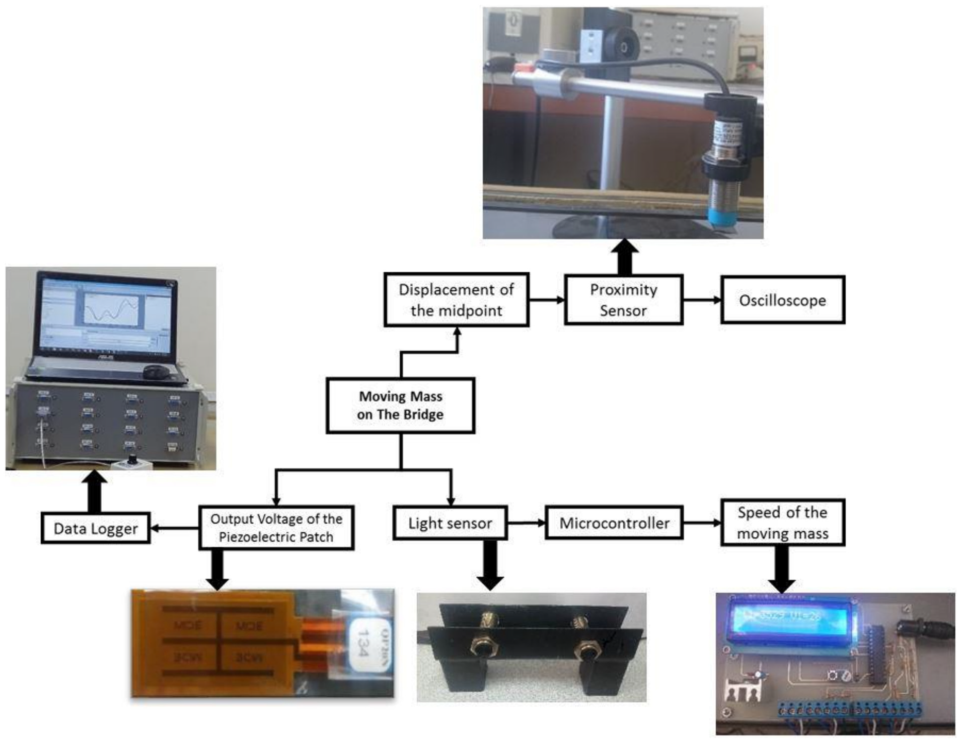
Data acquisition process flowchart.
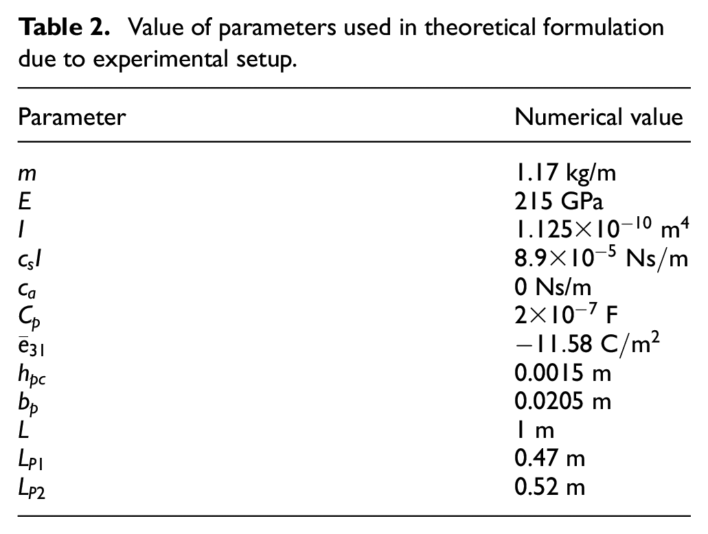
Numerical values of parameters used in experiments are listed in Table 2.
Value of parameters used in theoretical formulation due to experimental setup.
Results
The obtained results for midpoint displacements under moving mass can be seen in Figure 5.
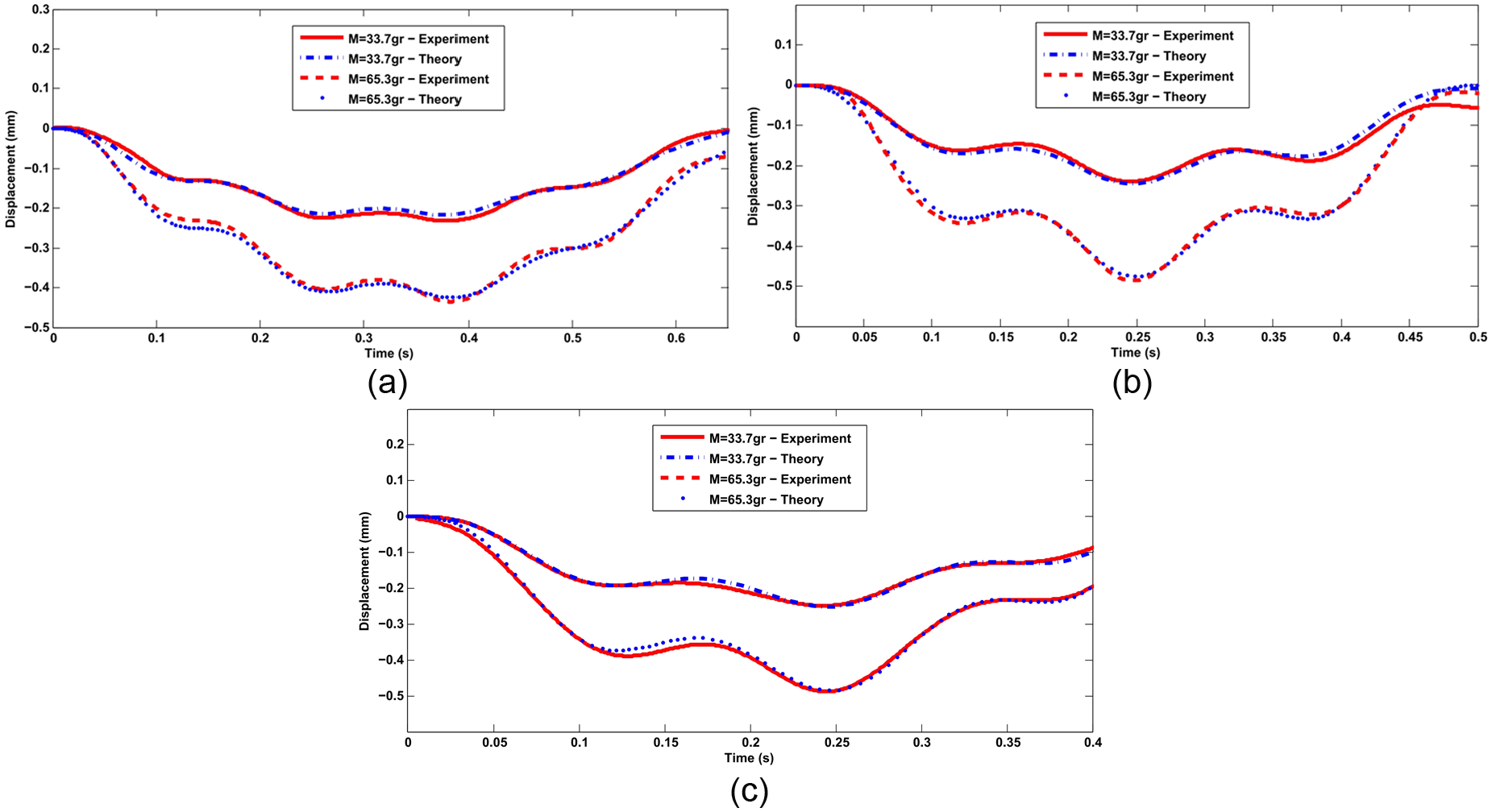
Comparison of experimental and theoretical displacement of beam’s midpoint under 33.7 and 65.3 g moving masses for (a) v = 1.5 m/s, (b) v = 2 m/s, and (c) v = 2.5 m/s.
As can be seen in Figure 5, displacements of middle point obtained from theoretical approach for moving mass are relatively in agreement with the experimental ones. It is noteworthy that the graphs of Figure 5 were also reproduced for the first three modes of the beam. However, the results showed small discrepancy compared to those obtained from the first fundamental mode of the structure. Therefore, it was decided to use only one mode in the afterward calculations.
The piezoelectric patch, which is attached on the beam, is parallel with a resistive load R and a data logger with 1-MΩ resistance. When the resistive load R is omitted from the circuit, data logger is displaying the near open-circuit voltage. The system can be functionalized both for obtaining the open-circuit output voltage and the closed circuit one. Beam vibration will produce a voltage in the piezoelectric patch, but the piezoelectric patch, in general, has a reaction against beam vibration. We performed a test in order to justify the negligibility of the piezoelectric coupling effect on the beam response. In this test, the piezoelectric patch was attached on the beam and then moving mass passed across the beam while once the piezoelectric was in open-circuit mode and the other time it was in short-circuit mode. As can be seen in Figure 6, inconsiderable difference between these two experiments approves the negligibility of the piezoelectric coupling effect.
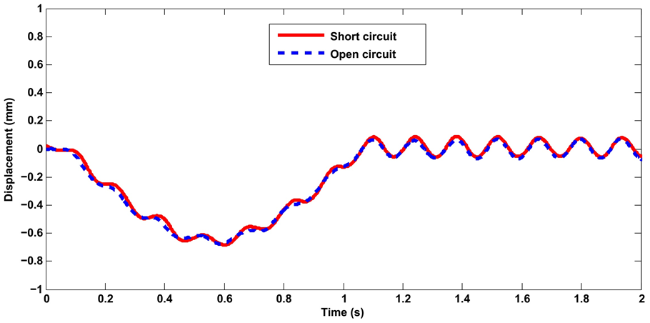
Comparison between beam response for short-circuit and open-circuit mode of piezoelectric.
Figure 7 shows the comparison between near open-circuit voltage gained from the theoretical and the experimental tests.
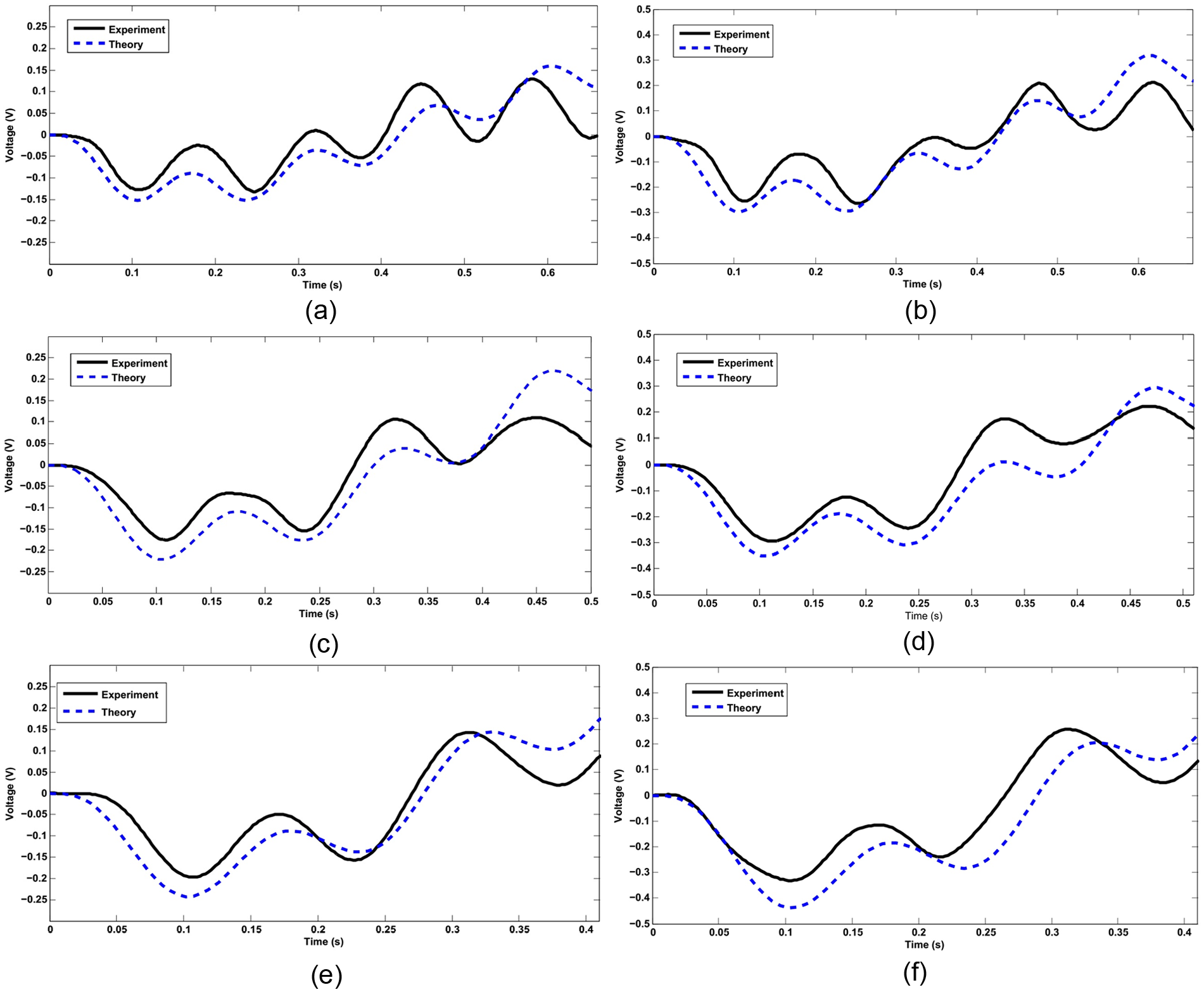
Comparison of theoretical and experimental induced open-circuit voltage for (a) M = 33.7 g, v = 1.5 m/s; (b) M = 65.3 g, v = 1.5 m/s; (c) M = 33.7 g, v = 2 m/s; (d) M = 65.3 g, v = 2 m/s; (e) M = 33.7 g, v = 2.5 m/s; and (f) M = 65.3 g, v = 2.5 m/s.
Figure 7 shows that output voltage rises mainly by increasing mass in a constant moving speed and also enhances with much less rate by increasing the speed. The comparison between theoretical and experimental values of average harvested power from Figure 7 is listed in Table 3, which clearly shows the effects of increasing in the moving mass and moving speed. So, to increase the harvested power, one can increase the moving mass or the moving speed.
Value of average harvested power from presented data in Figure 7.
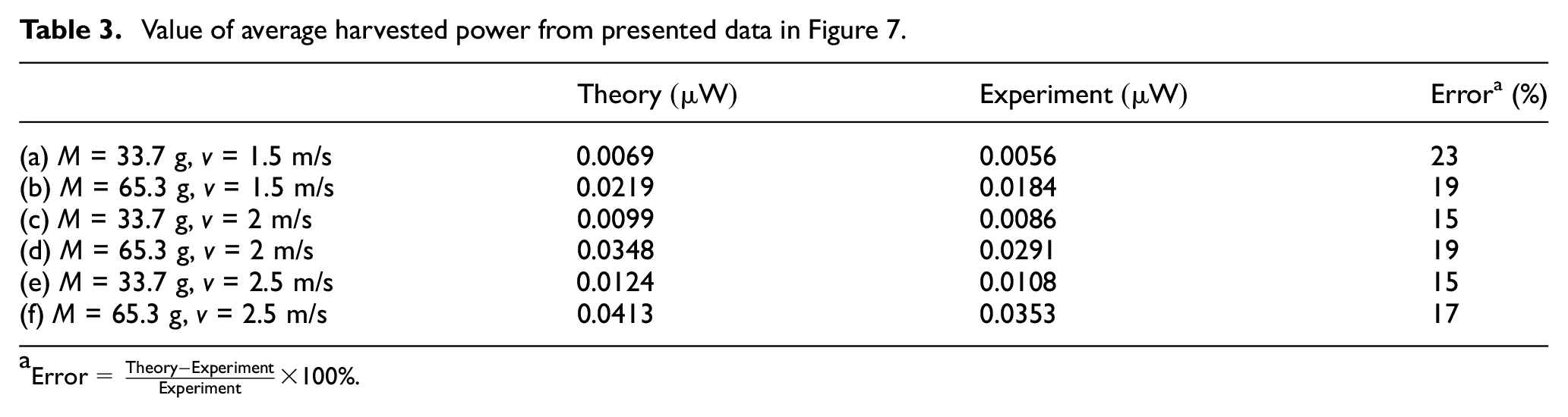
The power displayed in this table is obtained using root mean square of voltage based on equation (10)
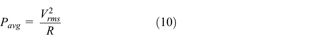
The theoretical power for different values of resistive load (R) can be seen in Figure 8. The power displayed in this figure is obtained using equation (10).
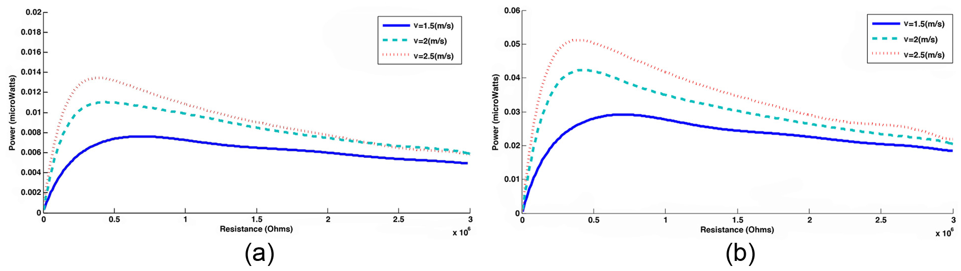
Harvested power at various load resistances (R): (a) M = 33.7 g and (b) M = 65.3 g.
The optimum resistive load that maximizes the harvested power can be obtained from Figure 8. As an instance for M = 65.3 g and v = 2.5 m/s, the optimum power is 0.052 µW which occurs for R = 0.4 MΩ. As seen in this figure, the optimum resistive load
Conclusion
In this study, energy harvesting from a highway bridge was investigated. The highway was modeled with a simply supported beam. The effect of car moving on the highway was represented by a moving mass. A simple formulation based on the first fundamental mode of the beam was presented which is able to calculate the amount of energy harvested from the beam during traveling a moving mass. An experimental setup of the beam and piezoelectric patch was constructed and the piezoelectric power and the beam response during traveling the mass were measured. The results indicate a relatively good agreement between analytical and measured values.
The results indicate that in a constant moving mass speed, the piezoelectric voltage and power were increased by increasing the mass. Also, in a constant mass value, the piezoelectric output was increased by increasing the moving mass speed. This is mainly due to the fact that the beam midpoint deflection and strain increases by increasing the traveling mass value.
Harvested power at various load resistances at a constant mass value was also calculated. It is found that the harvester power versus load resistances starts from zero, reaches a maximum value, and then by further increasing in the resistance it remains almost constant. The optimum value of load resistance for each moving mass and moving mass velocity can be extracted from the corresponding graph. For example, the results specify that for moving load of 65.3 g and moving velocity of 2.5 m/s, the optimum power is 0.052 µW which occurs at a resistance load of 0.4 MΩ.
Footnotes
Declaration of Conflicting Interests
The author(s) declared no potential conflicts of interest with respect to the research, authorship, and/or publication of this article.
Funding
The author(s) received no financial support for the research, authorship, and/or publication of this article.