
Abstract
Shape memory alloys are attractive engineering materials due to their potential application as actuators using the ability to memorize shapes through a thermomechanical loading. This article develops a numerical investigation of different shape memory alloy actuator configurations considering bias and antagonistic arrangements. Numerical simulations are carried out using the finite element method together with a constitutive model for shape memory alloys. Parametric analysis is carried out evaluating the performance of each actuator configuration based on stress and strain. Basically, four representative configurations of general actuators are treated: shape memory alloy wire, linear spring connected to a shape memory alloy wire, two elastic springs connected by a shape memory alloy wire, and two shape memory alloy wires connected by a spring.
Introduction
Shape memory alloys (SMAs) have been used as functional materials or intelligent sensors/actuators in a wide variety of applications in various fields of human knowledge such as medical, civil and mechanical engineering, automotive, aerospace, and communication applications (Andreasen and Hilleman, 1971; Cragg et al., 1983; Desroches and Delemont, 2002; Dong et al., 2008; Kohl et al., 2002; Wilde et al., 2000). Operational characteristics of SMA actuators are related to thermal and/or mechanical loadings that induce phase transformations. Several materials present the general thermomechanical behavior of SMAs and, among them, it is important to highlight the following: NiTi; Cu-based alloys as CuAlNi, CuZnAl; and Fe-based alloys as FeCrNiMnSi, FeMnSiCrNi, and FeCrNiMnSiCo (Bhuniya et al., 2005; Cingolani et al., 1999; Kikuaki et al., 1986; Moriya et al., 1991; Sato et al., 1982). Materials such as thin films, composites, and foams are other possibilities that exhibit SMA properties (Lester et al., 2015).
SMAs have remarkable characteristics that are exploited as actuators, such as shape memory effect (SME), superelasticity, or pseudoelasticity, and stress-assisted two-way memory effect (SATWME). Devices based on SMAs can be related to small forces or displacements as micro-actuators, such as micropumps, microvalves, microgrippers, microswitches, and micropositioners (Choudhary and Kaur, 2016; Hoxhold and Büttgenbach, 2008; Huang et al., 2004; Nespoli et al., 2010), but it is also associated with systems that require great strength or torque actuation (Dong et al., 2008; Jansen et al., 2004; Spaggiari et al., 2012; Strittmatter and Gümpel, 2004; Paik and Wood, 2012; Zhang and Yin, 2012).
Shape memory actuators may present several configuration arrangements, design of which depends on specific application. In general, actuators are developed using shape memory element combined with bias springs or antagonistic elements (Monteiro et al., 2013; Sofla et al., 2008; Strelec and Lagoudas, 2002). SATWME effect is usually employed to obtain actuators with good repetitiveness. In this regard, the analysis of different actuator arrangements is important to improve the device efficiency, defining the best design and potential application range for each specific application.
In this work, different SMA actuator configurations are investigated using a combination of SMA elements and elastic springs. Basically, four representative configurations of general actuators are treated: SMA wire (Wire (W)), bias elastic spring connected to an SMA wire (Spring–Wire (SW)), two elastic springs connected by an SMA wire (Spring–Wire–Spring (SWS)), and two SMA wires connected by an elastic spring (Wire–Spring–Wire (WSW)). Parametric analysis is performed defining different operational conditions to improve the actuator performance. The developed analysis considers installation and actuation stages defined by different thermomechanical loading processes and boundary conditions.
Finite element method (FEM) is employed for numerical simulations using a constitutive equation proposed by Savi and colleagues (Baêta-Neves et al., 2004; Monteiro et al., 2009; Paiva et al., 2005; Savi and Paiva, 2005) to describe the thermomechanical behavior of SMA. This model captures the general thermomechanical behavior of SMAs providing a proper description of different phenomena. Geometrical nonlinearities are also included into the formulation. An iterative numerical procedure based on the operator split technique (Ortiz et al., 1983) is employed in order to deal with the nonlinearities in the constitutive formulation. Newton’s method is used together with the orthogonal projection algorithm in order to deal with both geometrical and constitutive nonlinearities. Commercial code ABAQUS is employed using a user material routine (Bandeira et al., 2006).
Constitutive model
A constitutive model developed by Paiva et al. (2005) is employed to describe the thermomechanical behavior of SMAs. Besides strain,


where σ is the stress, and


where
Numerical simulations
FEM is employed in conjunction with the presented constitutive equations to model SMA actuators. ABAQUS is employed with a user material routine (UMAT) (Bandeira et al., 2006). A two-node element with Lagrange shape functions is employed using the truss elements, T2D2. This is a one-dimensional bar that is deformed only by axial stretching being pin jointed at their nodes.
Model verification
Model verification is now in focus. Material parameters are determined from experimental tests conducted using a NiTi-based SMA wire (54.8% Ni and 45.2% Ti) with 1.71 mm diameter, 200 mm length. Characterization of SMA is performed considering two tests: digital scanning calorimeter (DSC) test and tensile test.
DSC test defines phase transformation temperatures using the NETZSCH 200 F3 Maia. By defining
Experimental results are employed to calibrate numerical model. Parameters employed for numerical simulations are presented in Table 1, being employed in all the simulations, using
Model parameters.
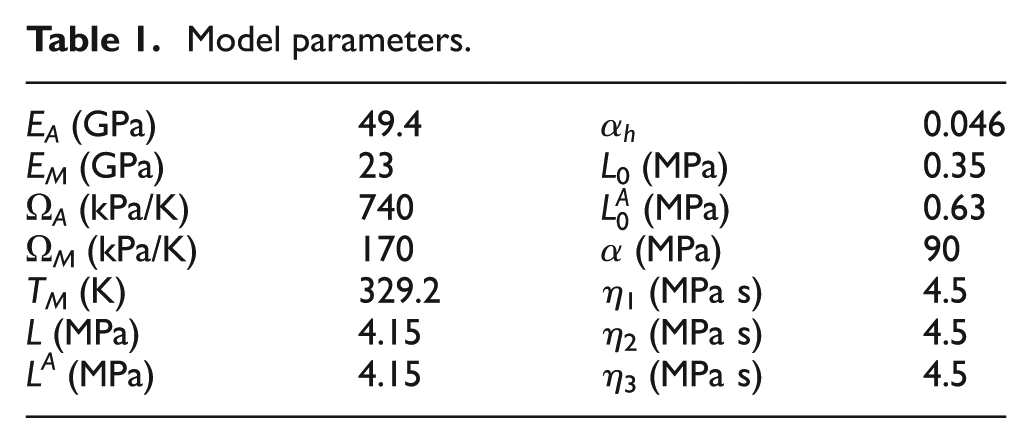
Figure 1 presents results of numerical simulations. Stress–strain curve establishes a comparison between numerical and experimental results obtained as an average of three SMA samples, showing a good agreement. It also presents the volume fraction time history showing phase transformation evolution from twinned to detwinned.
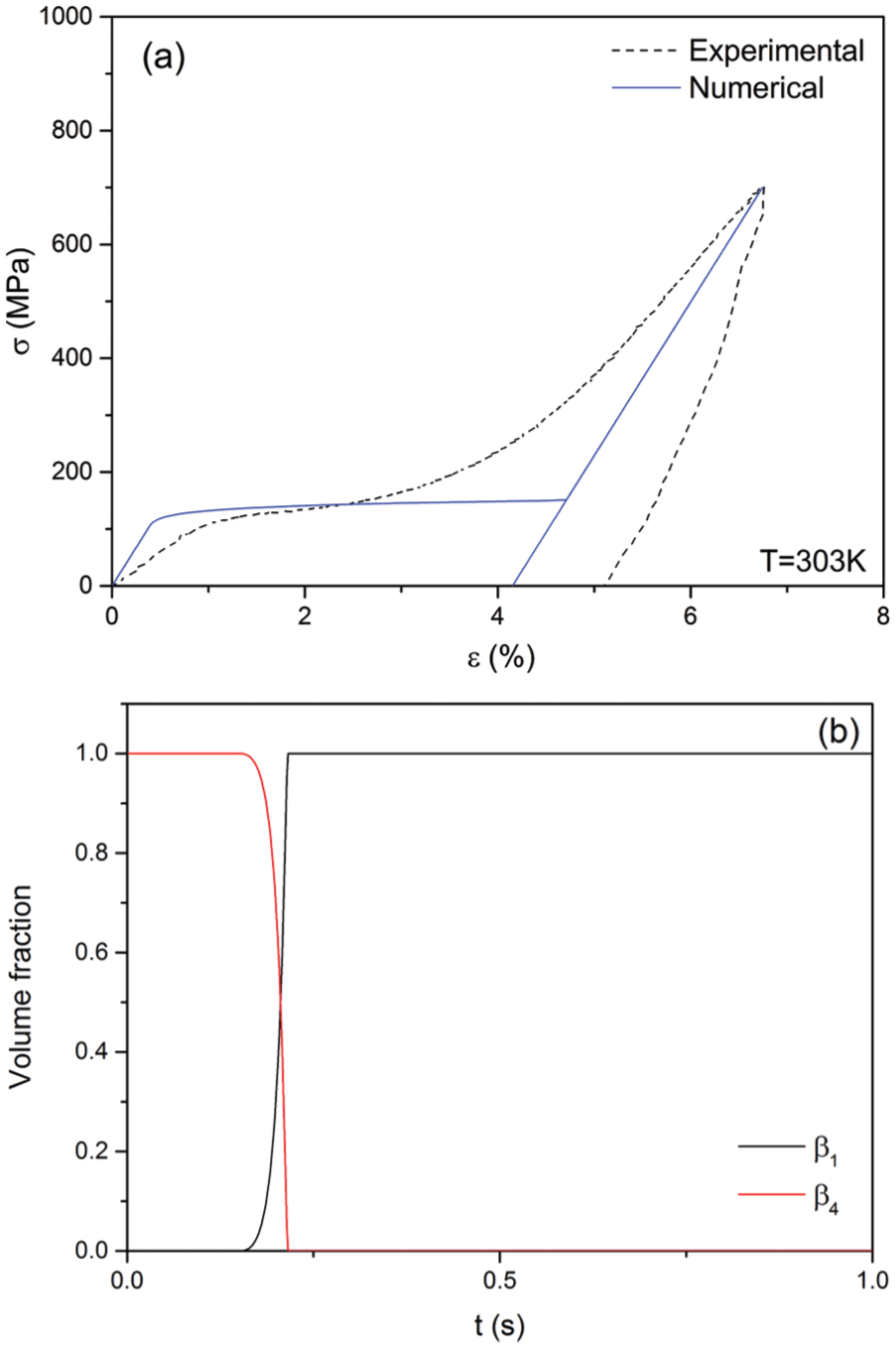
Shape memory effect: (a) stress–strain curve showing a comparison between experimental and numerical results and (b) martensitic volume fraction evolution.
After the model verification, different actuator configurations are investigated. The different actuators have distinct objectives associated with distinct operational functioning conditions. Figure 2 presents the four representative configurations of general actuators that are treated: SMA wire (W), bias elastic spring connected to an SMA wire (SW), an SMA wire between two springs (SWS), and two SMA wires connected by two springs (WSW). The thermomechanical loading process and boundary conditions are defined in order to establish a two-stage procedure: installation and actuation stages. Initially, a mechanical loading of prescribed stress is applied defining the installation stage. Afterward, thermal loading defines the actuation stage. The main characteristics of these stages depend on actuator and will be explained separately. Parametric analysis is performed defining different actuator characteristics, as applied force or spring stiffness, monitoring the actuator performance analysis, usually defined by stress or strain values.
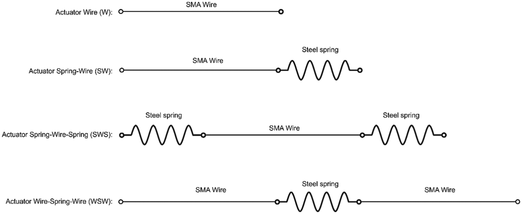
Schematic diagram of the actuator configurations.
SMA wire (actuator W)
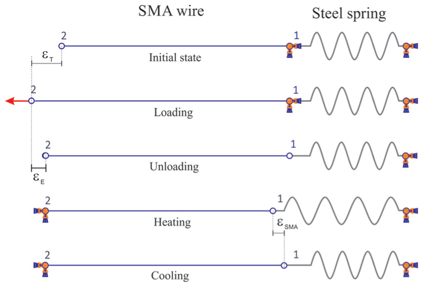
The analysis of SMA actuators starts with a wire. Figure 3 presents the thermomechanical loading process defining typical actuator operational conditions. For the wire actuator, the installation stage is represented by fixing the right end (point 1) and by applying a mechanical load at the left end (point 2). This mechanical loading produces stress-induced reorientation of martensite being incrementally applied from 0 to 700 MPa, where
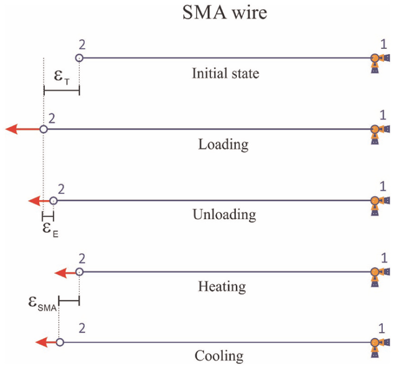
Actuator W: schematic diagram of the simulation performed with a shape memory wire.
Mechanical and thermal loadings employed are shown in Figure 4. Note that if the mechanical load is completely removed, one-way SME is induced. Other cases simulate situations where SMA actuation is against an applied force. All simulations are performed in a similar way, using the sequence: loading–unloading–heating–cooling.
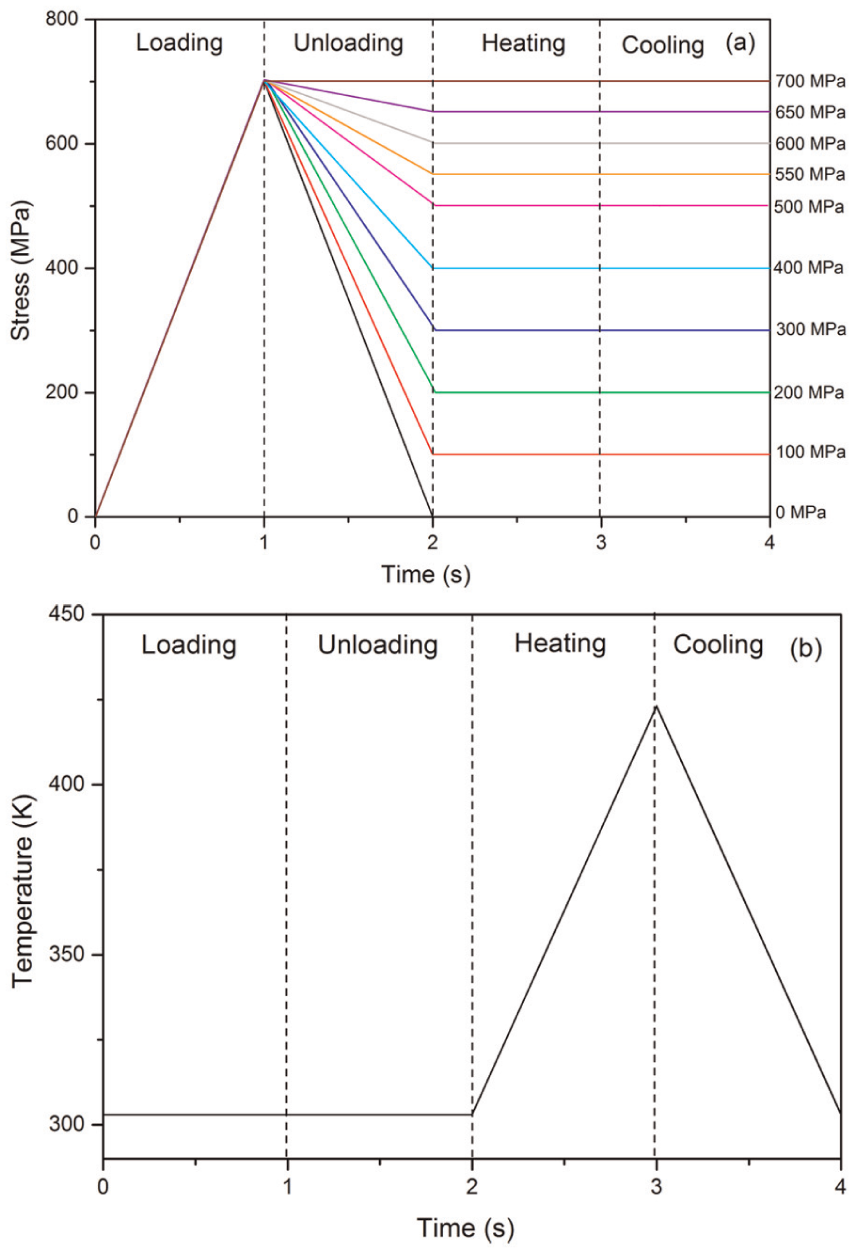
Actuator W: (a) mechanical loading and (b) thermal loading process.
Results related to the actuator W are presented in Figure 5 in the form of strain time history during the thermal loading, actuation stage. The different strain values at the beginning of thermal loading are due to different values of elastic recovery (εE) obtained when the mechanical level is sustained after the end of the mechanical unloading. Figure 5 allows one to determine the actuator effective strain, εSMA, recovered during the thermal cycle. These results show a gradual decrease in the strain restored at the end of the cooling process from a given stress level (SATWME). As expected, the reverse transformation induced by heating the sample in a stress-free state can fully recover the inelastic strain and SMA returns to its original shape of the austenitic phase (SME). It is important to emphasize that the transformation temperature depends on the applied load value. Note that higher values of the applied load lead to higher transformation temperatures required for the activation of the phase transformation, as can be seen in Figure 5. This process can be better observed through the volume fraction time history presented in Figure 6.
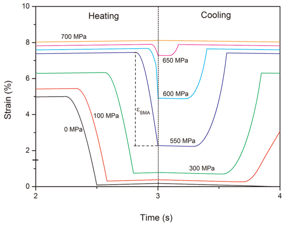
Actuator W: strain evolution during thermal process.
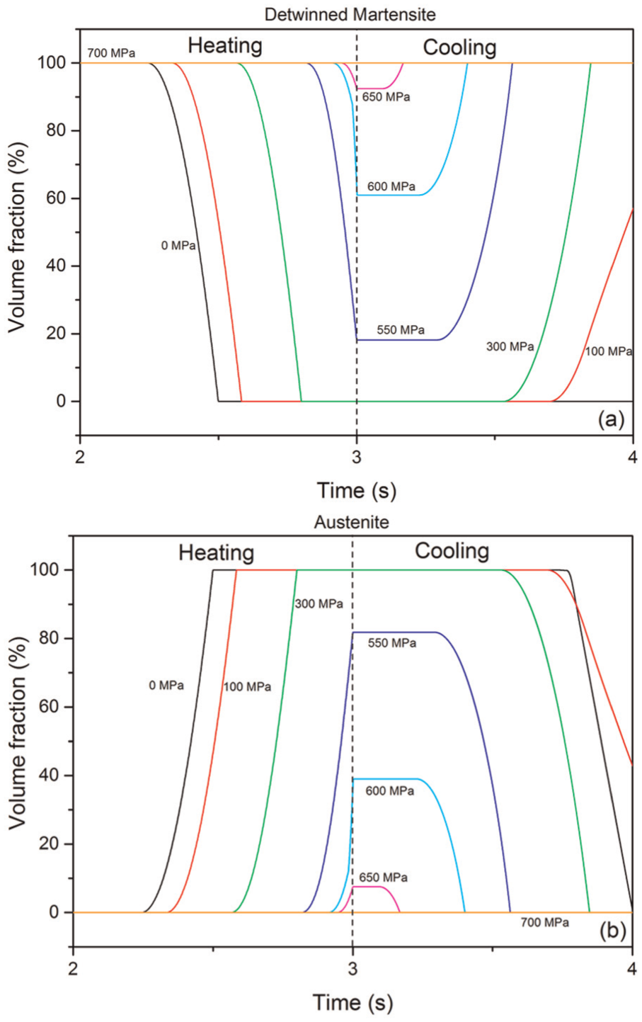
Actuator W: volume fraction evolution during heating/cooling process: (a) detwinned martensite and (b) austenite.
Figure 6 shows that for high stress levels, detwinned martensite transformation to austenite is not completed, resulting in a reduction in the SME. The transformation occurs through the exchange of detwinned martensite by austenite up to the saturation point, which is limited by the stress level. On the other hand, for low stress level (100 MPa), the reverse transformation does not finish either, because there is not enough stress to induce the detwinned martensite, which also tends to decrease the SME for the subsequent cycles.
Figure 7 shows the stress–strain–temperature curves for different applied stress levels, which allow a better comprehension of the phase transformations. Note that after the mechanical loading, the thermal loading induces different hysteresis depending on the applied load level.
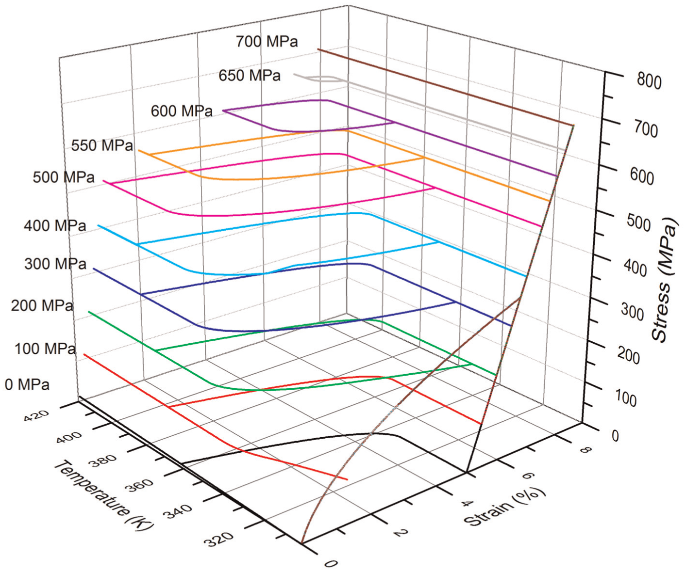
Actuator W: stress–strain–temperature for different applied stress levels.
Actuator characteristics are now evaluated considering the recoverable strain (εSMA) for different applied stress levels (Figure 8). Note a sharp drop of the recovered strain above 500 MPa, which is due to the incomplete phase transformation shown in Figure 6. This curve can be used for actuator design based on its main objective.
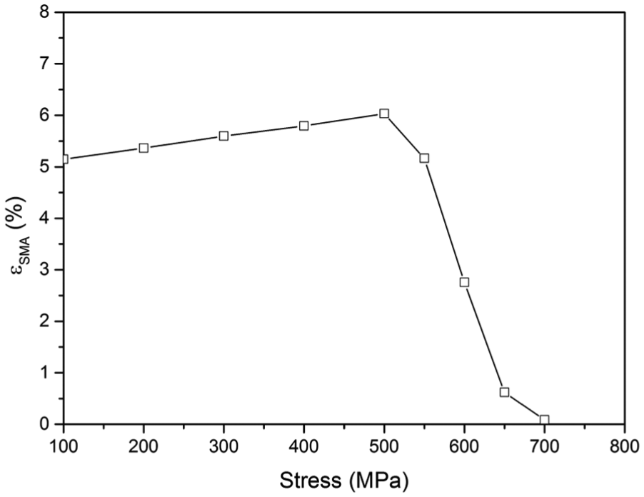
Actuator W: recoverable strain for different applied stress levels.
SMA wire connected to a linear elastic spring (actuator SW)
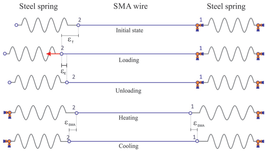
Actuator SW is composed by an SMA wire coupled with a bias linear elastic spring. The actuator design involves the evaluation of different spring stiffness values. Figure 9 shows a sequence of thermomechanical loads as well as the boundary conditions employed for the actuator investigation. Initially, installation stage is represented by a mechanical loading that is incrementally applied on the left wire end (point 1) up to the value of 700 MPa, while the other wire end remains fixed (point 2). Afterward, the fixed boundary condition at the right wire end (point 2) and the mechanical load is completely removed. Then, the left wire end (point 1) is defined as a fixed boundary condition, and the thermal loading process is imposed to the actuator, defining the actuation stage in a similar way of the previous case shown in Figure 4(b).
Actuator SW: schematic diagram of the simulation performed with an SMA wire–spring actuator.
During the actuation stage, the increase in temperature generates a recovery force due to phase transformation, pulling the spring and promoting an energy store. Afterward, when the SMA is cooled, the energy stored in the bias spring is released, deforming the SMA wire back to its initial position. Note that this process depends on the spring stiffness, K, which is essential for the actuator design.
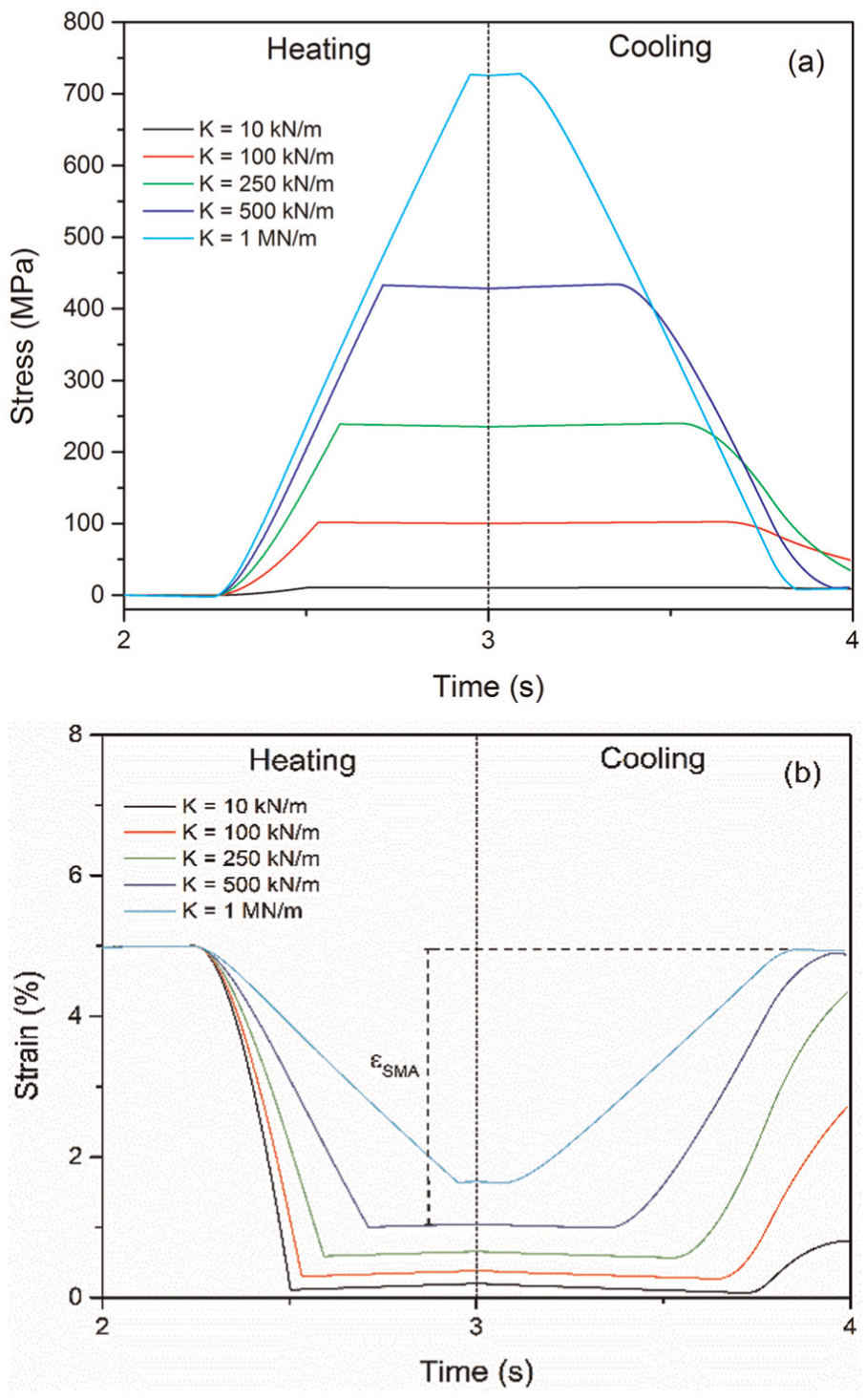
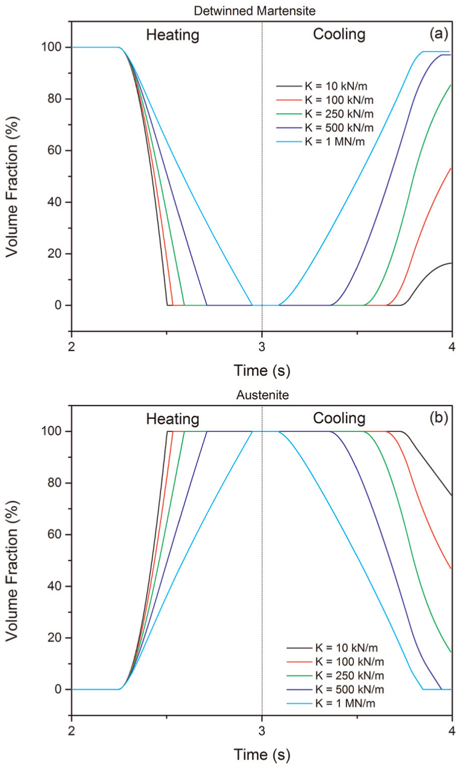
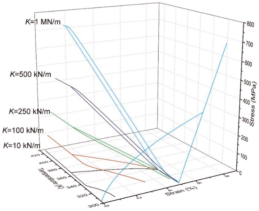
Figure 10 shows the stress and strain time history during the thermal loading. The actuator effective recoverable strain during a thermal cycle is represented by εSMA. Figure 11 shows the volume fraction evolution of detwinned martensite (Figure 11(a)) and austenite (Figure 11(b)). It can be observed that for some configurations, defined by the spring stiffness, phase transformation becomes incomplete. Figure 12 shows the entire process of loading–unloading–heating–cooling in the form of stress–strain–temperature curves as a function of the spring stiffness. Note that stiffness defines a slope of the curve, establishing the level of recoverable strain.
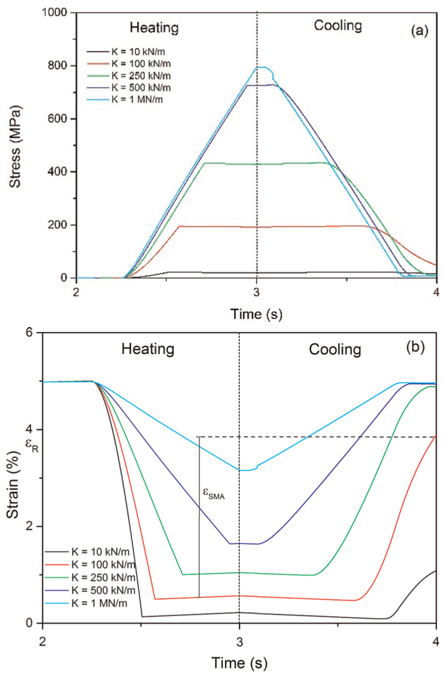
Actuator SW: (a) stress and (b) strain evolution curves for different spring stiffness during thermal process.
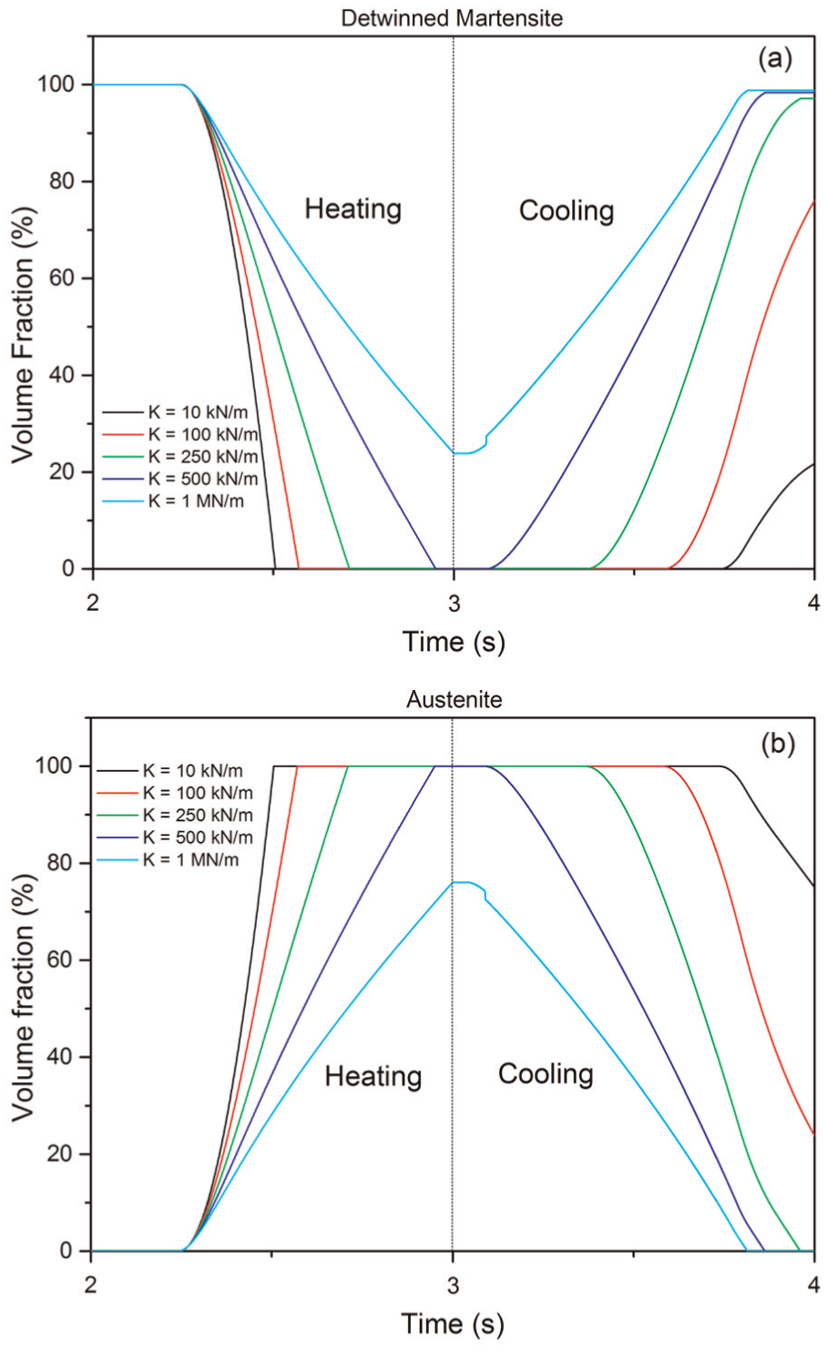
Actuator SW: volume fraction evolution of (a) detwinned martensite and (b) austenite for different spring stiffness during thermal process.
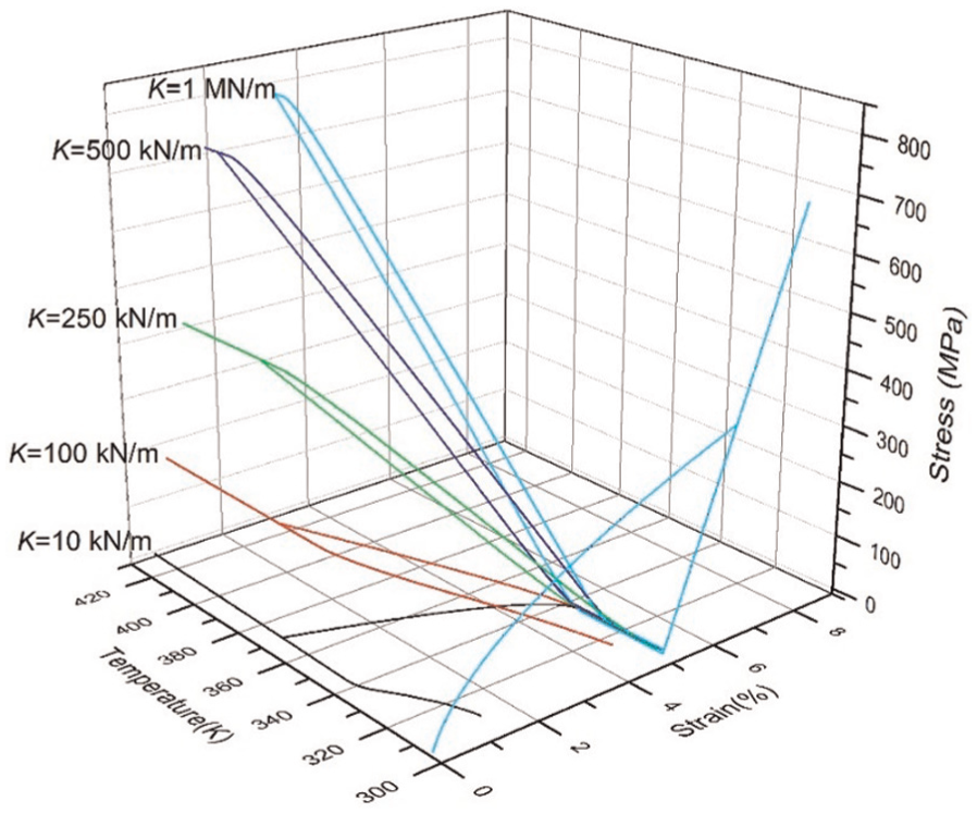
Actuator SW: stress–strain–temperature curves for the whole mechanical–thermal process for different spring stiffness.
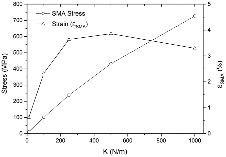
Figure 13 presents the general actuator behavior showing SMA stress and recoverable strain as a function of the spring stiffness (K). Note that the recoverable strain has a maximum value about 4% for stiffness values close to K = 100 kN/m.
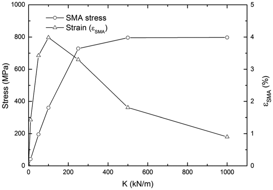
Actuator SW: curves for SMA stress and recoverable strain for different spring stiffness.
Two linear elastic springs connected to an SMA wire (actuator SWS)
A different actuator configuration is now in focus considering a combination of two linear elastic springs connected by an SMA wire, defining actuator SWS. The schematic representation of the actuator and the loading process are shown in Figure 14.
Actuator SW: schematic picture of the simulation performed with a spring–wire–spring actuator.
The loading sequence is carried out as follows: initially, a pre-load up to 700 MPa is applied at point 2 and then unloaded, with point 1 fixed (see Figure 14). This mechanical procedure represents the installation stage. Under this condition, both springs do not develop residual strain after unloading. After this stage, the ends of both springs are fixed, and the fixation of point 1 is removed. Actuation stage represents actuator operational condition that is achieved by the application of thermal loadings (Figure 4(b)) on the SMA wire. Results of this actuator are presented in Figure 15 in the form of SMA stress (Figure 15(a)) and strain (Figure 15(b)) during the heating and cooling cycle. Figure 16 presents the displacement of each end of the wire connected to springs, showing symmetrical displacement behavior.
Actuator SW: (a) stress and (b) strain evolution during thermal process.
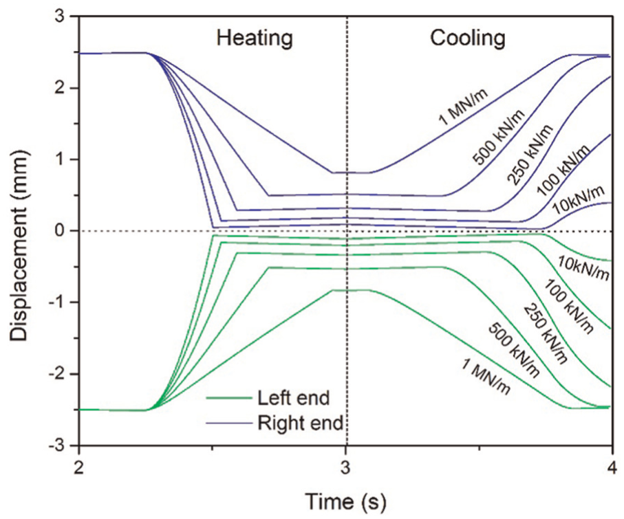
Actuator SW: displacement of both ends of SMA wire during thermal process.
Figure 17 shows volume fraction evolutions for the actuator SWS. Once again, it is observed that for some configurations, defined by the spring stiffness, the phase transformation is not completed, which affects the maximum strain presented by the system, as shown in Figure 15(b).
Actuator SW: volume fraction evolution of (a) detwinned martensite and (b) austenite during thermal process.
Figure 18 presents the whole thermomechanical process for different values of spring stiffness in the form of stress–strain–temperature curves. Note that the slope of the curves is associated with spring stiffness values and defines the recoverable strain.
Actuator SW: stress–strain–temperature curves for different spring stiffness.
Figure 19 shows a comparative analysis of SMA stress and recoverable strain values for different spring stiffness. As expected, actuator stress increases with increase in increasing stiffness. It is noticeable that a recoverable strain drop for spring stiffness values larger than 500 kN/m confirms the efficiency loss.
Actuator SW: curves for SMA stress and recoverable strain for different spring stiffness.
Two SMA wires connected to a linear elastic spring (actuator SW)
A new actuator configuration is now of concern considering two SMA wires connected by a linear elastic spring called actuator SW. Figure 20 presents a schematic picture showing the installation and actuation stages. Once again, the simulation is carried out considering a pre-loading process of the wires without loading the spring, which is simulated by the fixation of points 1 and 3. After the mechanical unloading of the wires, the fixation is changed to points 2 and 4, starting the actuation stage imposing thermal loadings. Basically, both wires are subjected to thermal loadings, defining different actuation procedures. Simulations consider that the heating sequence begins in the left wire, followed by its cooling, and then the right wire is heated and cooled, as shown in Figure 21.
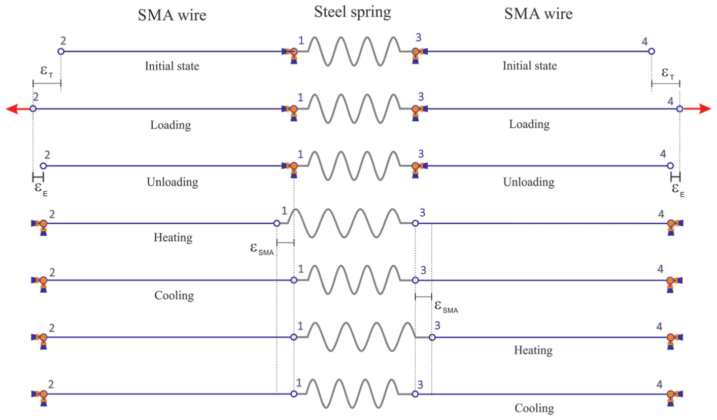
Actuator SW: schematic picture of the simulation performed with an SMA–spring–SMA actuator.
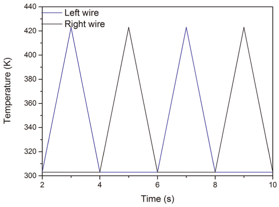
Actuator SW: actuation thermal loading process.
Figure 22 shows the stress evolution during thermal loadings for different spring stiffness. It should be highlighted that both wires have the same stress, since the actuator has a symmetric response.
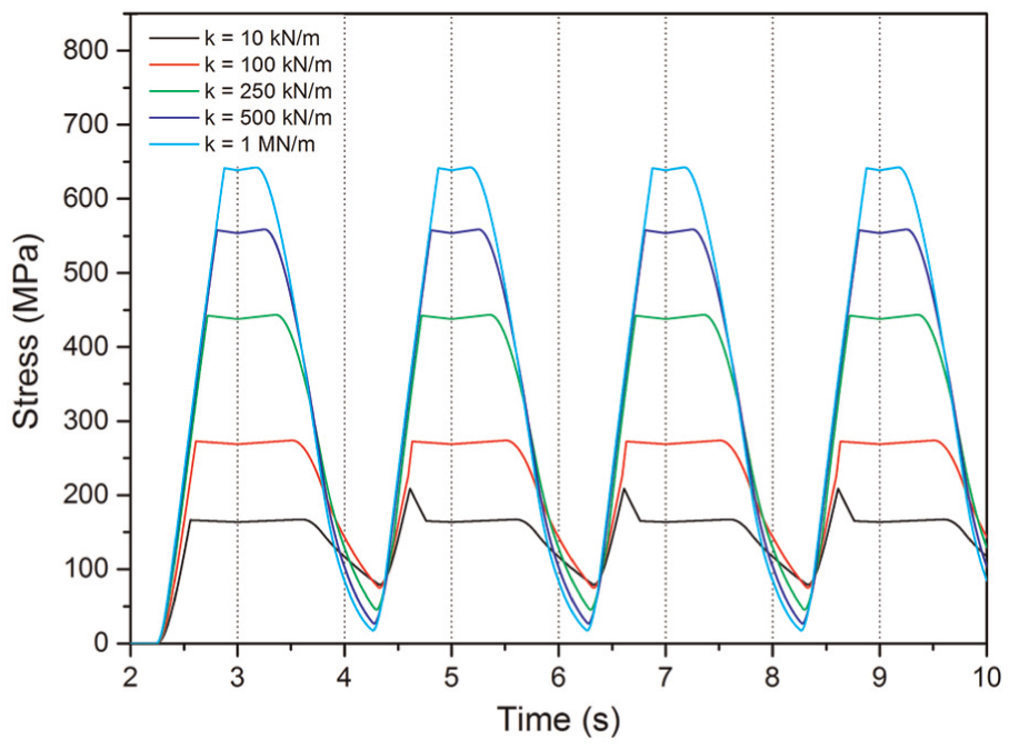
Actuator SW: stress evolution during thermal process for different spring stiffness.
Figure 23 shows the strain evolution for both left (Figure 23(a)) and right (Figure 23(b)) wires and different spring stiffness values. Labels H and C represent regions where heating and cooling of each wire occur, respectively. Note that actuators are promoting movement for left and right sides. The thermomechanical behavior of both wires is equal, since thermal and mechanical loadings are the same. These behaviors are observed with a delay, since they occur in different time instants (Figure 21). Volume fraction evolutions allow one to confirm responses associated with the actuator (Figure 24). Once again, labels H and C represent heating and cooling regions, respectively.
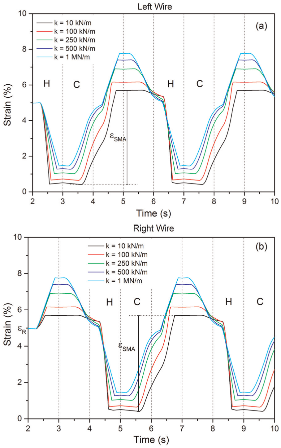
Actuator SW: strain evolution during two cycles of thermal process for (a) left wire and (b) right wire.
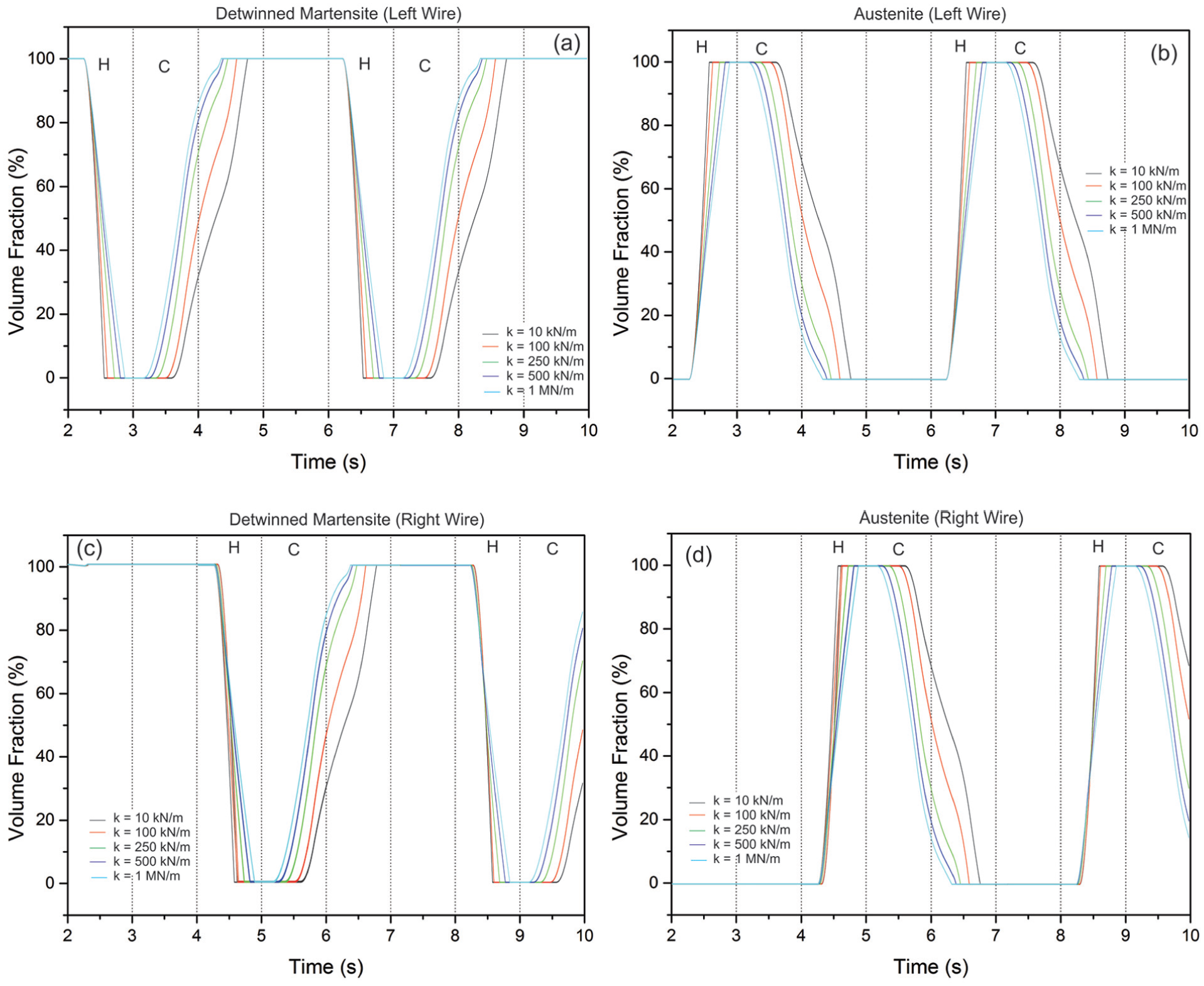
Actuator SW: (a) volume fraction evolution of detwinned martensite, (b) austenite, (c) detwinned martensite, and (d) austenite during heating/cooling process for left wire and right wire, respectively.
Figure 25 shows stress–strain–temperature curves for different spring stiffness. As the spring stiffness increases, the system becomes stiffer and stress–strain slope increases.
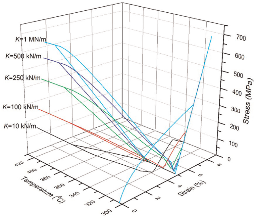
Actuator SW: stress–strain–temperature curves for different spring stiffness.
Analysis of SMA stress and recoverable strain for different values of spring stiffness is shown in Figure 26. Results confirm that the maximum SMA stress generated by the actuator is smaller than the previous cases. On the other hand, recoverable strain has an almost constant behavior for the spring stiffness range analyzed. Note that the use of two wires does not double the recoverable strain values when compared with the actuator WS (Wire–Spring). Based on that it is possible to observe that stiffness variation establishes a competition that defines the system response.
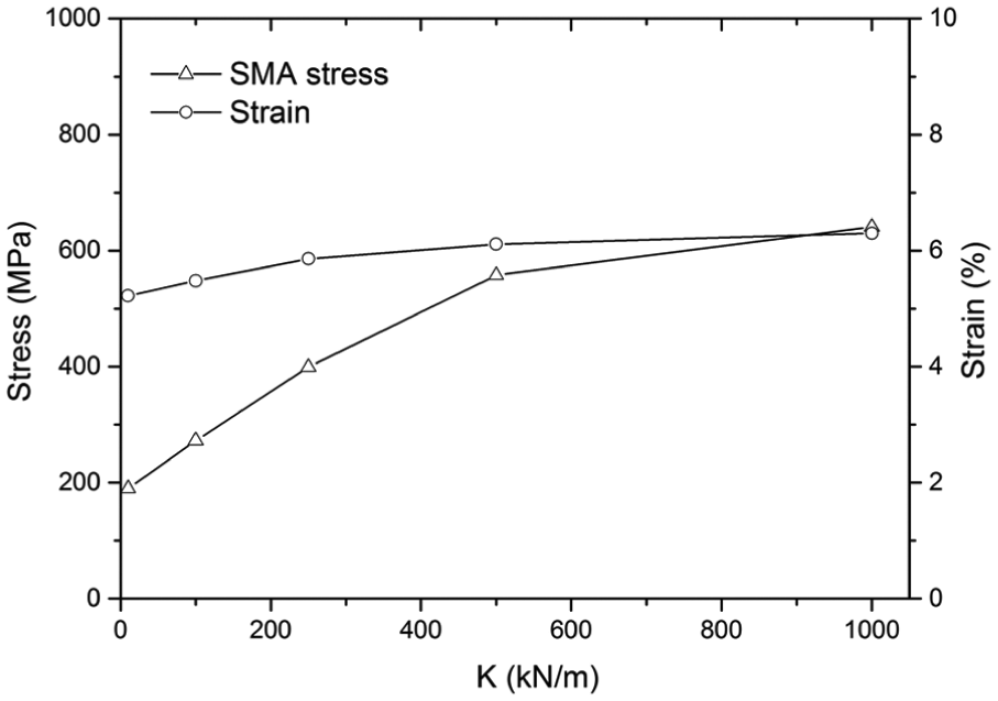
Actuator SW: curves for SMA stress and recoverable strain for different spring stiffness.
Comparison among actuators
A comparative study of different actuator configurations is now conducted. The idea is to analyze the characteristics of each actuator configuration and its performance in terms of stress and strain. Analysis is restricted to actuators built with springs: SW, WSW, and SWS. Initially, the generated force capacity is evaluated by considering the SMA stress of each actuator configuration (Figure 27). The maximum value reached by each actuator configuration is highlighted. In all cases, the maximum SMA stress is reached at the larger stiffness value, K = 1 MN/m. It is also noticed that for this stiffness value, actuators with a single SMA wire (SW and SWS) present a maximum SMA stress larger than the actuator with two wires (WSW). Moreover, there is a stabilization trend for higher values of spring stiffness for actuators SW and WSW.
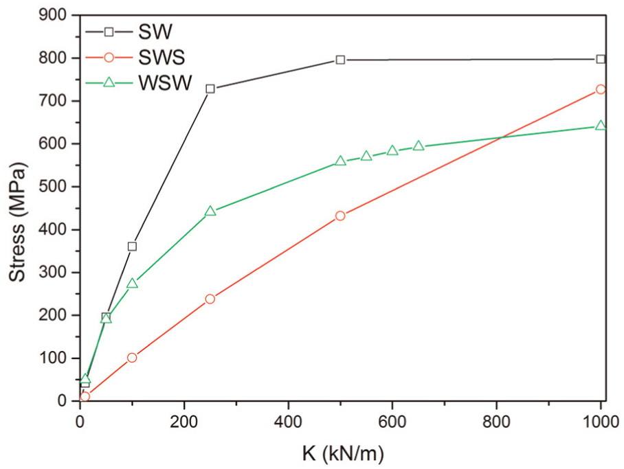
Comparative SMA stress results for different actuator configurations with distinct values of spring stiffness.
A different behavior is observed in terms of strain analysis. Figure 28 presents the recoverable strain curve for different spring stiffness for the actuators. Actuator SW presents recoverable strain that rises up to a maximum value of approximately 8% for a spring stiffness close to K = 100 kN/m and rapidly drops to small values with higher stiffness values. The configuration of two springs (SWS) presents a behavior where the increase in the spring stiffness value causes first a recoverable strain increase followed by a slight drop for the larger stiffness values. The actuator with two shape memory wires (WSW) has a different behavior. A recoverable strain of 5% is observed for the smaller stiffness value. For larger stiffness values, the recoverable strain increases slightly, about 1%, and afterward remains almost constant.
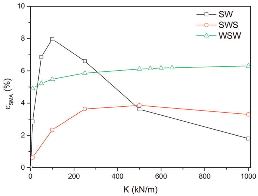
Comparative recoverable strain results for different actuator configurations for different spring stiffness.
Table 2 summarizes the maximum values for the actuator configurations analyzed. Results show that the different configurations have their own characteristics in terms of SMA stress, recoverable strain generated, and their relationship with spring stiffness. Nevertheless, all configurations present a similar behavior of a stress increase associated with the spring stiffness increase. Configuration W has an almost constant strain for low stresses; however, it rapidly loses the displacement efficiency at stress values above 500 MPa. Configuration SW presents a maximum recoverable strain value (3.99%) for a stiffness of about 100 kN/m and rapidly decreases for higher stresses. Configuration SWS is similar to SW and has a maximum recoverable strain value (3.86%) for a stiffness of about 500 kN/m. These two configurations (SWS and SW) provide the highest SMA stresses among the actuators, 796 MPa, corresponding to a force of 1.82 kN. In terms of recoverable strain, the most interesting configuration is the actuator SW that presents an almost constant strain with a variation lower than 1% for the spring stiffness range considered. Nevertheless, it provides the lowest SMA stress value, 640 MPa.
Comparative results for maximum SMA stress and recoverable strain.
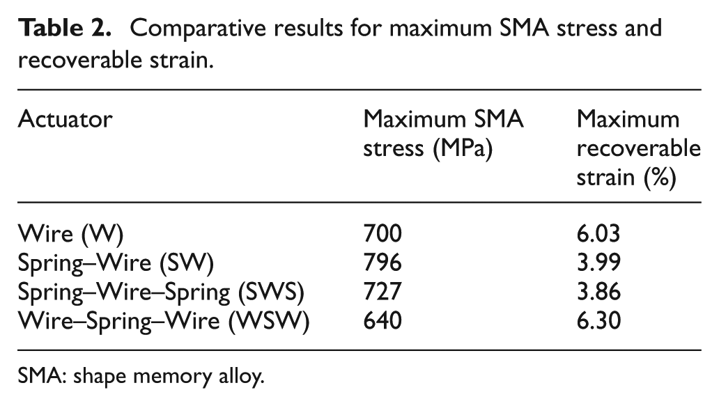
SMA: shape memory alloy.
Conclusion
This article compares different actuator configurations using SMA elements. FEM is employed considering four representative actuator configurations: SMA wire (W), SW, SWS, and WSW. Parametric analysis is performed defining different spring stiffness values or applied force that changes the actuator performance. Numerical simulations allow one to determine the maximum SMA stress and recoverable strain for each configuration. Spring stiffness values can be adjusted to achieve the best actuator performance. The proposed methodology can be employed for design purposes, defining the best configuration and parameters according to the desired actuation conditions.
Footnotes
Acknowledgements
The authors would like to acknowledge the support of the Brazilian Research Agencies CNPq, CAPES, and FAPERJ and through the INCT-EIE (National Institute of Science and Technology–Smart Structures in Engineering) the CNPq and FAPEMIG. The Air Force Office of Scientific Research (AFOSR) is also acknowledged.
Declaration of conflicting interests
The author(s) declared no potential conflicts of interest with respect to the research, authorship, and/or publication of this article.
Funding
The author(s) received no financial support for the research, authorship, and/or publication of this article.