
Abstract
In some energy harvesters, the maximum throw of the seismic mass is limited due to the physical constraints of the device. The shunt load resistance of such a harvester is generally selected based on the allowable throw of the mass when the device is subjected to the maximum level of excitation. However, the energy harvester with this value of shunt resistance does not perform well at lower levels of excitation. In this article, a variable load resistance, scheduled on the excitation level, is introduced to extend the dynamic range of an energy harvester in applications where excitation level varies. This method is applied to the design of an energy harvester, which comprises a sprung mass coupled to an electric motor through a lead screw. The dynamic equation and parameters of the system are introduced and the device is experimentally characterized, by conducting random vibration tests. The harvested power and the relative displacement are then obtained for different sinusoidal base excitation amplitudes when the system is excited at a frequency close to its natural frequency. It is demonstrated that the use of a variable load resistance mechanism can significantly improve the dynamic range and output power of the energy harvester.
Introduction
Over the last decade, the idea of harvesting electrical energy from ambient vibration and moving structures has been the subject of considerable amount of research, as discussed in a number of review papers including Harne and Wang (2013), Saadon and Sidek (2011) and Khaligh et al. (2010). These articles report vibration energy harvesting in a wide range of devices and applications. The majority of research is related to the applications with a vibration frequency of 10–20 kHz, and the power generation in the range of 10 µW–100 mW (Zuo and Tang, 2013). This level of energy is enough to power wireless sensors and low-power electronics. However, in some situations, the vibration can be very large, for example, the vibration of tall buildings (Tang and Zuo, 2011), vehicle systems (Choi et al., 2009), ocean waves (Uihlein and Magagna, 2016) and human motion (Siddique et al., 2015). In these applications, usually the frequency of vibration is less than 10 Hz; but due to the large amplitude of vibrations, the potential for harvesting energy from 1 W to 100 kW or more exists (Zuo and Tang, 2013). Recently, with the elevated concerns on the global energy and environmental issues, harvesting energy from the large-scale vibrations is more attractive and hence it has become one of the important research areas. The common means of converting vibration energy into electricity are electromagnetic (Siddique et al., 2015), piezoelectric (Saadon and Sidek, 2015) and electrostatic (Tao et al., 2015). Electromagnetic-based harvesters are preferred in situations where vibration has a large velocity or amplitude. Therefore, electromagnetic generators are the transducers of choice in the large-scale energy-harvesting applications.
Electromagnetic energy harvesters can be divided into two general groups. A linear energy harvester relies on a proof mass coupled to an electric generator whose relative movement is, directly or indirectly, caused by a reciprocating source of vibration. This type of device is particularly suitable for high-frequency low-amplitude excitations and not so efficient for the other extreme case of low-frequency high-amplitude environment (Hendijanizadeh et al., 2013a). However, in some applications such as harvesting energy from boat vertical motion (Sharkh et al., 2011) or tall building vibrations (Cassidy et al., 2011; Marian and Giaralis, 2015), the frequency of vibration and hence the relative speed of the proof mass is low. Therefore, a direct drive generator can be quite large and expensive relative to the amount of power it produces, that is, the power density of the generator will be very low. This is due to the fact that the size of an electric generator is proportional to its torque (or force in a linear generator) and accordingly the power density is proportional to its speed. Compared to a linear generator, a rotary generator is dimensionally smaller and more cost-effective. Therefore, in some energy-harvesting systems, an intermediate mechanism is utilized to convert a linear low-frequency motion to a high-frequency rotational motion to reduce the size and cost of the device (Cassidy et al., 2011; Hendijanizadeh et al., 2013a; Sharkh et al., 2011). The intermediate part, for instance a lead screw, provides an additional design parameter to the existing ones and hence improves the efficiency of system in ‘constrained applications’. In general, energy harvesters suggested in the literature have two fundamental limitations. First, they are designed to operate at certain frequencies and any difference between the excitation frequency and the natural frequency of the harvester will dramatically reduce the efficiency of the device (Harne and Wang, 2013). Second, due to the physical constraints, the oscillating mass only moves within a specified range (Hendijanizadeh et al., 2013b). In contrast to the first issue, the second has received less attention in the literature and is discussed in this article. Normally, energy harvesters are designed so that the resonance frequency of the device matches the excitation frequency, and it is known that the throw of the mass is attenuated when the excitation frequency deviates from the natural frequency of the device. However, the mass throw is directly proportional to the base excitation amplitude. Hence, controlling the vibration performance of the structure is crucial to avoid jeopardizing the performance of the device when it is subjected to the high amplitude of vibration. The importance of vibration control is highlighted especially in the large-scale systems, as the protection of the mechanical structure and the human passenger or occupants is given priority for these applications (Zuo and Tang, 2013). Therefore, when the energy harvesters are subjected to a variable amplitude excitation, they are designed for their maximum excitation level, in order to achieve a safe and efficient performance. However, when the transducer is excited below its maximum excitation level, it operates in a sub-optimum condition. Recently, a nonlinear cubic electrical damping has been introduced to extend the dynamic range of energy harvesters (Ghandchi-Tehrani and Elliott, 2014). It was shown that a system with shunted cubic damping could harvest more power at resonance compared with a linear harvester, when excited below its maximum excitation level.
A rotational energy harvester, to harvest energy from vertical motion of boats, has been proposed in Hendijanizadeh et al. (2015). However, the manufactured energy harvester reported in Hendijanizadeh et al. (2015) was an over-damped system, which is not desirable in terms of efficiency. This article describes a modified version of the rotational energy harvester in Hendijanizadeh et al. (2015) with reduced mechanical viscous damping and Coulomb friction. The experimental results of testing the modified energy harvester are presented. It will be shown that when the device is subjected to excitation of different amplitudes, the amount of output power of the system can be dramatically increased by employing an intelligently selected variable load resistance.
Device modelling and numerical simulation
Mathematical modelling
It is assumed that the rotational energy harvester, shown in Figure 1, is subjected to an excitation of variable amplitude. The device is designed to harvest energy from vertical motion of a boat or buoy. It comprises a sprung mass coupled to an electrical generator via a ball screw. The boat’s vertical motion causes the mass to oscillate relative to the boat, which in turn drives a generator through the ball screw coupling. Figure 2 shows a schematic of the proposed rotational system in Figure 1, where k is the spring stiffness,
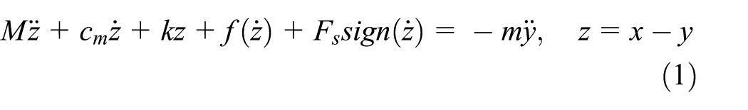
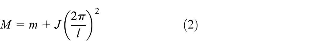
where y is the displacement of the base and x is the displacement of the mass, and the total effective mass is
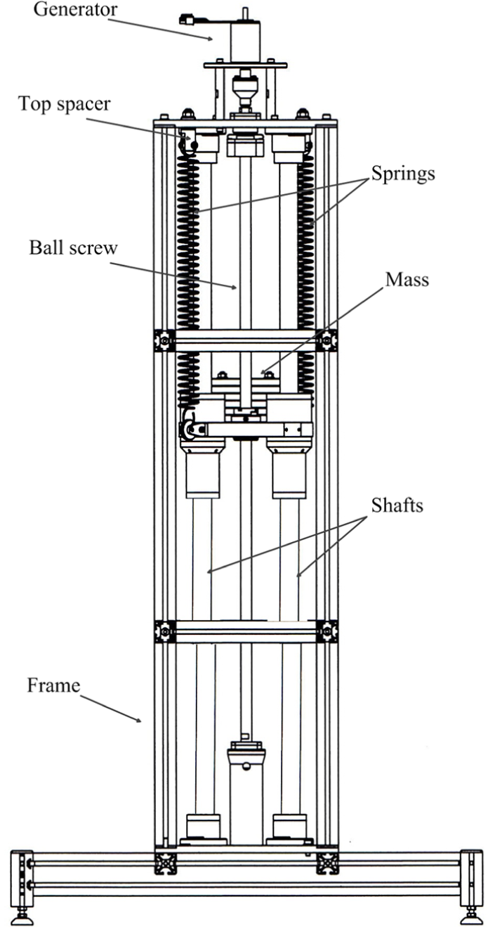
Drawing of the ball screw–based energy harvester (Hendijanizadeh et al., 2015).
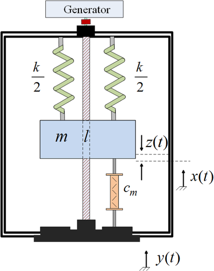
Schematic of the lead screw–based energy harvester (Hendijanizadeh et al., 2015).
Many papers on generating energy from vibrations indicate that the effect of the generator’s internal inductance is negligible. Cammarano et al. (2010) show that even in cases (such as high-frequency applications) where the effect of the internal inductance cannot be ignored, the undesirable effect of the internal impedance can be compensated by adding a capacitor in series with the circuit. Figure 3 shows the equivalent electrical circuit of the energy-harvesting device in which a capacitor is added in series with the load reactance to cancel the effect of the generator’s inductance. The produced voltage by the generator

Equivalent circuit of an electromagnetic generator connected to a resistive load.
Also, it can be shown that if the generator is attached to a linear resistance

where
The natural frequency is
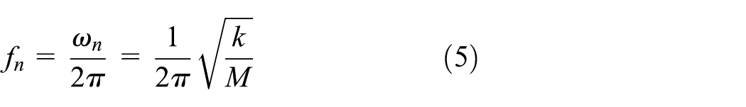
when driven at this natural frequency, the output power supplied to the load is
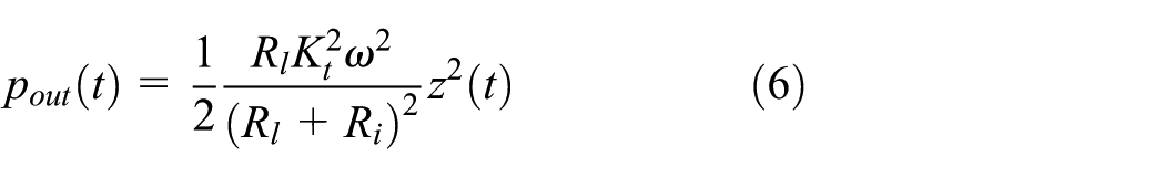
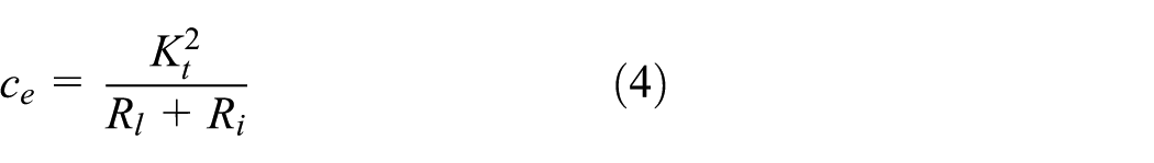
whereby defining
Stephen (2006) has shown that for a linear energy harvester, the maximum electrical power from a resonant system, without constraint on the maximum throw of mass, is obtained when the load resistance is set to be equal to
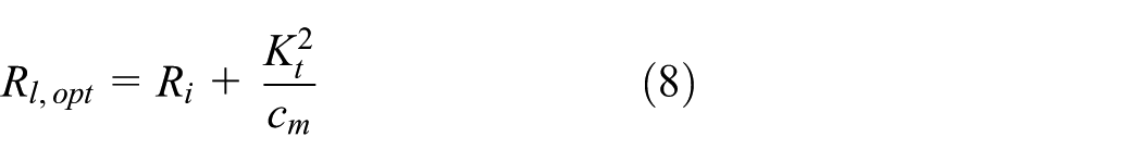
where the parameter
Numerical simulation
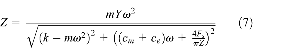
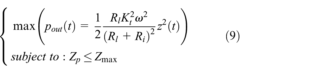
From equation (7), it is known that the relative displacement of the mass depends on the base excitation amplitude and the electrical damping; therefore, when the device is subjected to a variable amplitude excitation, one can select the load resistance so that the mass oscillates within the defined constrained when the base excitation is maximum. However, having a system with constant load resistance results in suboptimal performance when the system is excited at the amplitudes below the maximum excitation level. Therefore, in an ideal energy harvester, an active tuning mechanism should be employed to solve equation (9) for each level of excitation and select the optimum load resistance to maximize the output power with respect to the defined constraint.
To verify this approach, an energy harvester with parameters shown in Table 1 is modelled in Simulink. The Simulink model is solved numerically using a variable-step fourth- and fifth-order Runge–Kutta method and relative tolerance of 0.001. It is assumed that the system is subjected to a base vibration with a frequency that matches the natural frequency of the modelled energy harvester, that is,
Parameters of the lead screw–based energy harvester.
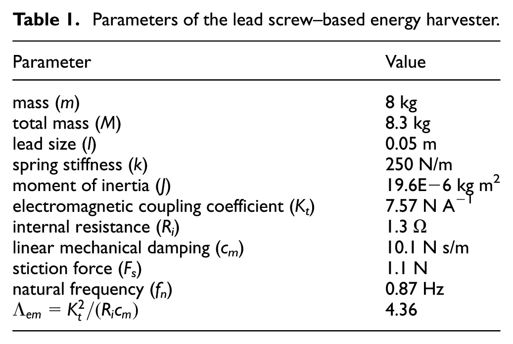
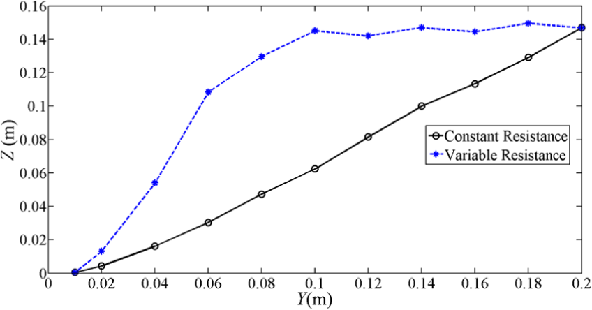
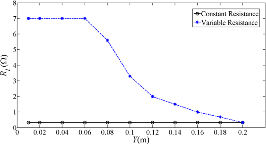
Figure 4 shows the relative displacement of the mass as a function of the input amplitude when driven at resonance, for both the harvester with constant load resistance (black solid line) and harvester with variable load resistance (dashed blue line). The variable load resistance has been chosen to give the same throw as for the maximum excitation amplitude. For the excitation levels below the maximum amplitude, the relative displacement of the system with constant load declines, whereas the system with the variable load resistance can keep the maximum level of throw for a wide range of excitations. In both systems, for excitation level below 0.01, the mass does not have any relative displacement, due to the stiction force. Figure 5 shows the selected load resistances in both conditions. The system with constant load resistance is tuned so that the relative displacement of mass when Y = 0.2 m does not exceed
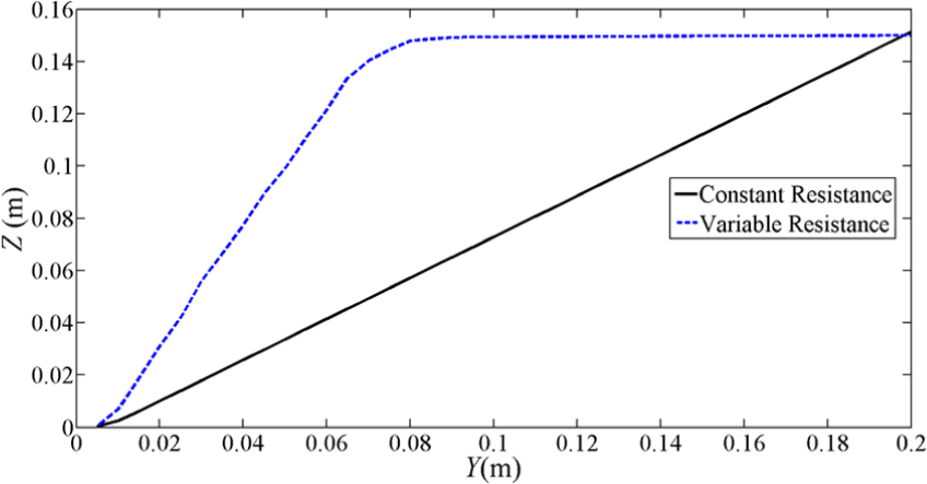
Simulations results presenting the relative displacement of the energy harvester with constant load resistance (solid line) and variable load resistance (dashed line), for different excitation levels when the rotational energy harvester is subjected to the different base excitation amplitudes.
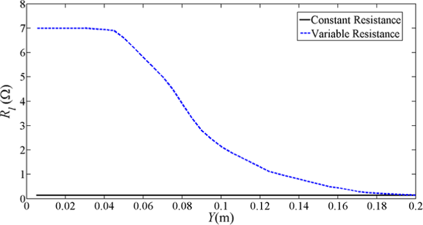
Simulations of the selected load resistance when the rotational energy harvester with constant load resistance (solid line) and variable load resistance (dashed line), is subjected to the different base excitation amplitudes with variable and constant load resistance.
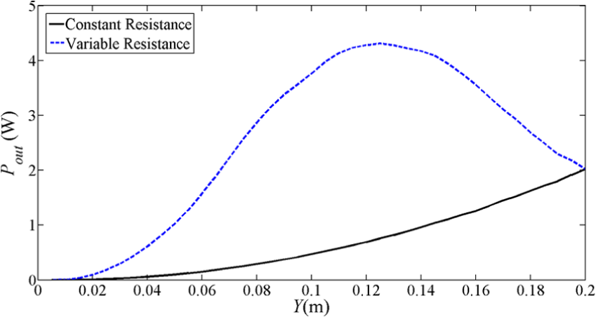
Simulations of the output power of the rotational energy harvester with constant (solid line) and variable (dashed line) load resistance when system is subjected to the variable excitation amplitude with variable and constant load resistance.
Figure 7 illustrates the ratio of the output power of the energy harvester with variable load resistance to that produced by the harvester with constant load resistance, for different levels of excitation. It is seen that utilizing the active mechanism to tune the load resistance can increase the output power by an order of magnitude for the excitation levels between 0.02 and 0.07 m.

The ratio of the output power in the system with variable load resistance over the power of the produced power by the system with constant load resistance for different levels of excitation, obtained from the numerical simulation results.
Experimental procedure
Device parameters
The energy harvester presented in this article is a modified version of the energy harvester described in Hendijanizadeh et al. (2015). The parameters of the current version of the energy harvester are shown in Table 1. The previous rotational energy harvester was an over-damped device. By replacing the ball screw of device with a new lead screw (Drylin, 2015) and with some redesigning to reduce the ball bearing friction, the stiction force and the mechanical damping of device have dramatically been reduced. To estimate the Coulomb friction of the energy harvester, some free vibration tests were performed. The equilibrium positions of the mass in two modes were first marked. In the first mode, the mass was pushed down until the springs were extended to nearly their maximum allowable limit and then released. Considering

In the second mode, the mass is pushed up and then released. The new equilibrium position is different than that of the first mode. Considering

The distance between the equilibrium positions in these two modes is 9 mm. By subtracting equation (11) from equation (10), we have
In order to measure the damping of the system, a small white piece of paper was attached to the oscillating mass of the lead screw–based system. Then, a camera was installed at the distance of 0.70 m away from the harvesters to cover to full range of the motion of the white paper. To obtain a good contrast between the under observation white paper and the other parts of the device, the components near the object point are covered with black tape. The camera in this experiment can catch the motion of device with the speed of 29.7 frames/sec. The physical parameters of the device including its mass, lead size, spring stiffness and total moment of inertia are as those shown in Table 1. Figure 8(a) shows the captured frame of the device at the equilibrium position, and Figure 8(b) shows the mass position at the start of the free oscillation test. In the free oscillating mass test, the position of the mass is plotted as a function of time. Then, by having the other physical parameters of system and solving the dynamic equation of system shown in equation (1) with ode45 algorithm for different values of damping, the best estimation of the damping coefficient of system can be obtained by matching the simulation results with the experimental one.
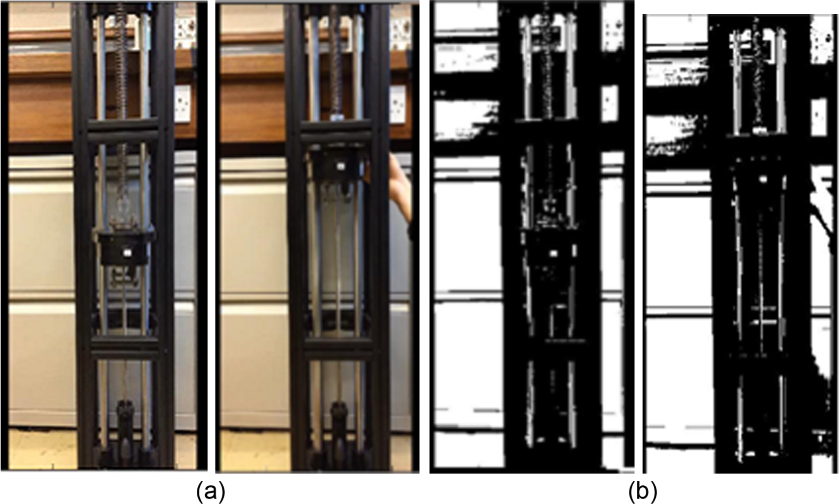
The captured frames at the start and end of the free oscillation test: (a) captured frame and (b) converted frame to black and white format.
The mechanical damping of the system, based on the curve fitting shown in Figure 9, is estimated to be
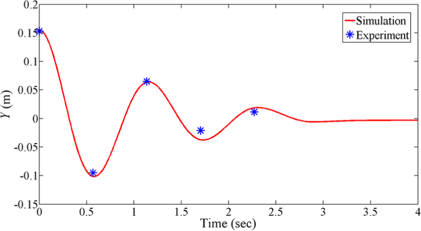
The position of oscillating mass in the free oscillation test of the rotational energy harvester for
In the previous version of device studied in Hendijanizadeh et al. (2015),
Experiment setup and device characterization
A set of experiments are carried out to characterize the modified rotational energy harvester and then to validate the idea of utilizing a variable load resistance to increase the output power of system when it is subjected to variable amplitude excitation. Figure 10 shows the schematic of the experimental setup used to test the manufactured energy harvester. In this setup, the harvester is mounted on a horizontal electro-hydraulic vibrator, and the generator terminals are connected to a variable resistor. Two micro-electro-mechanical system (MEMS) accelerometers, manufactured by Silicon Designs with the sensitivity of 800 mV/g and the dynamic range of ±5 g, are attached to the oscillating mass and the shaker. A voltage sensor is used to measure the voltage across the generator terminals where the load resistance is connected. The movement of the shaker is controlled by an amplifier model FE-376-IPF from Fylde Electronic Laboratories Ltd (2015). The voltage output signal and the accelerations of the mass and the shaker are captured by a data acquisition (DAQ) system from National Instruments (2015), with a sampling rate of 512 Hz. Figure 11 shows the actual implementation of the test rig, including the energy harvester, shaker and the electrical circuit (different load resistances). The acceleration of the shaker is recorded by channel 1 of the DAQ system, and the acceleration of mass is captured by the channel 2 of the DAQ system. The relative acceleration is obtained by subtracting the acceleration of mass from the base acceleration.
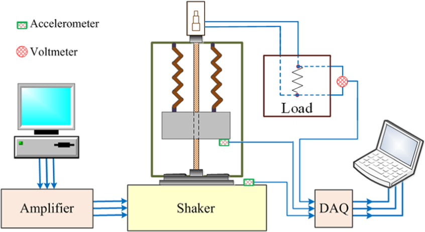
Schematic of the experimental setup.
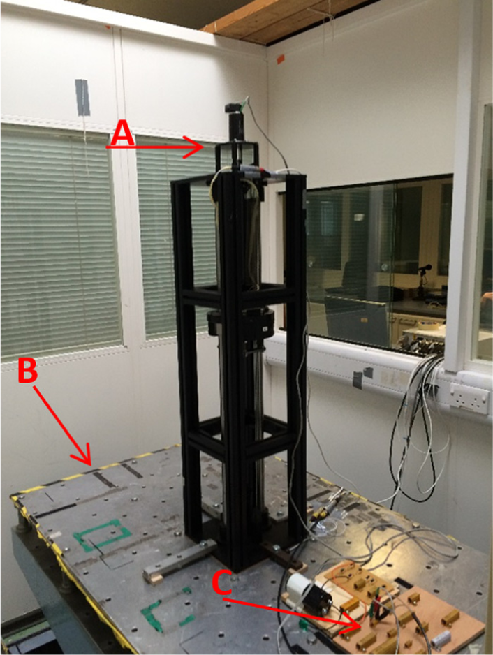
Actual implementation of energy harvester: (A) energy harvester, (B) shaker and (C) electrical circuit.
The first set of experiments is carried out to characterize the modified energy harvester. The energy harvester was subjected to a random signal with bandwidth of 10 Hz for 300 s and the sampling frequency of 512 Hz. The purpose of this experiment is to find the relative response (defined as the relative acceleration over the base acceleration), the resonance frequency and evaluate the effect of load resistance on the dynamic performance of device. Figures 12 and 13 show the amplitude and phase of the relative response, respectively, which is calculated from the ratio of the cross-spectral density (CSD) between the relative acceleration and the base acceleration over the power-spectral density (PSD) of base acceleration of system for open circuit,
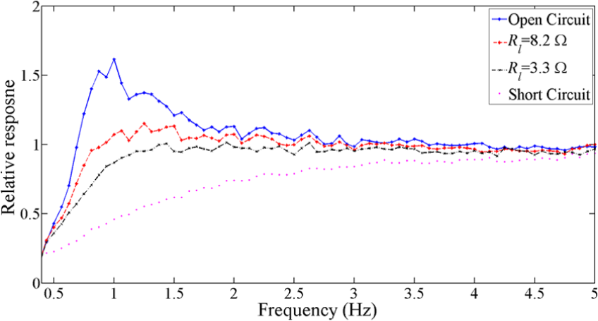
The measured amplitude (m) of the relative response of the rotational energy harvester in four different load conditions, obtained from the experimental results with random excitation test for the conditions of open circuit (-), Rl = 3.3 Ω (–), Rl = 8.2 Ω (-·-·) and short circuit (.).
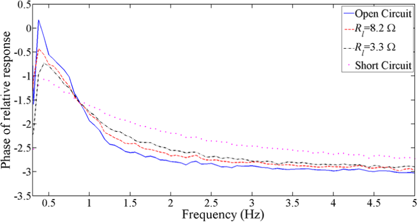
The measured phase (rad) of the relative response of the rotational energy harvester in four different load conditions, achieved from experimental results with random excitation test for the conditions of open circuit (-), Rl = 3.3 Ω (–), Rl = 8.2 Ω (-·-·) and short circuit (.).
The measured coherence between the base acceleration and the relative acceleration of mass for four different conditions is shown in Figure 14. The dynamic behaviour of system seems more linear for lower values of the load resistance. This could be due to the fact that the lower values of load resistance produce a larger linear electrical damping, as in equation (4), which reduces the nonlinear effect of the stiction force in the system.
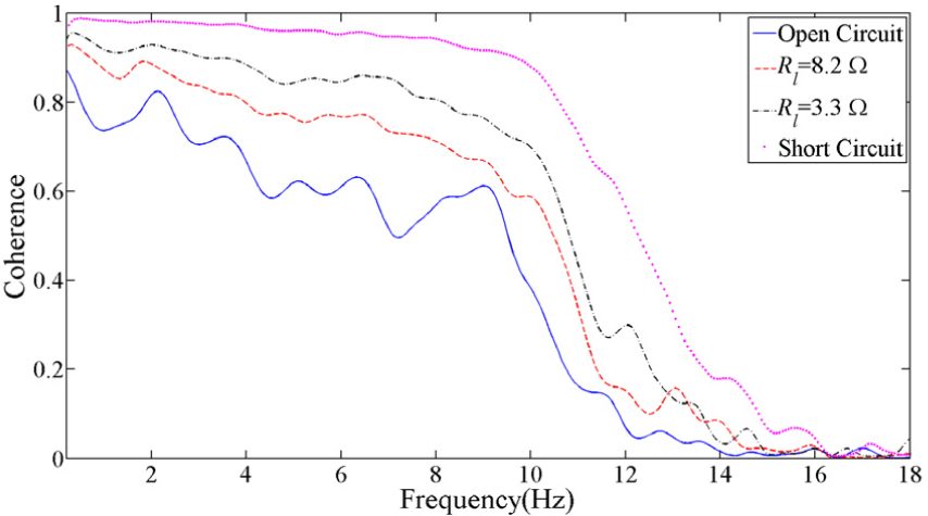
The measured coherence between base acceleration and relative acceleration for four different load conditions achieved from the experimental results with random excitation test for the conditions of open circuit (-), Rl = 3.3 Ω (–), Rl = 8.2 Ω (-·-·) and short circuit (.).
Extending the dynamic range of the energy harvester with variable load resistance
The main aim of this investigation is to demonstrate the idea of utilizing the variable load to extend the dynamic range of the energy harvester. In this experiment, the rotational energy harvester was subjected to a variable amplitude excitation with a frequency of 0.9 Hz, which is close to the natural frequency of the energy harvester, and the shaker excitation level is varied between 0.01 and 0.2 m. Similar to the procedure in the numerical simulation section, the performance of the energy harvester is evaluated in both constant and variable load resistance conditions. For the constant load resistance condition case, the load resistance is selected so that for the maximum excitation level, the relative displacement is close to 0.15 m. In practice, this is achieved when the load resistance is 0.33 Ω. However, for the system with variable load resistance, the load resistance is tuned to harvest the maximum power with respect to the defined constraint for the maximum allowable relative displacement of the mass. In this experiment, it is assumed that the maximum throw of the mass is 0.15 m. Figure 15, shows the experimental result of the relative displacement of the mass for both systems with constant and variable load resistance. It is seen that both systems have the same throw when they are subjected to a base excitation with the maximum amplitude of 0.2 m; however, by reducing the excitation level, the throw of the mass is declined. In contrast, for the system with variable load resistance, the relative displacement remain relatively constant for the excitation level from 0.2 to 0.1 m. Also, for the excitation levels from 0.1 to 0.01 m, the relative displacement of the mass is significantly larger than the system with constant load resistance. Figure 16 shows the selected load resistance for different excitation levels in both cases.
Experimentally obtained relative displacement of mass with variable and constant load resistance for different excitation levels.
Selected load resistance used in the experiments for different levels of excitation to harvest maximum power within the defined constraint.
Figure 17 shows the average harvested output power in both conditions. Similar to the numerical simulation results, it is seen that the system with a variable resistance can produce significantly more power over a wide range of excitation amplitudes. For the sake of comparison in terms of trend and the shape of results, the numerical results shown in Figure 6 are added to Figure 17. Figure 18 shows the ratio of the output power of the harvester with variable load resistance over the system with constant resistance. It is seen that the system with variable load resistance can produce more power compared with the system with constant load resistance. For instance, for the case of Y = 0.06 m, the produced power by the system with variable load resistance is almost 11 times greater than the harvested power from the device with the static resistance. In fact, the high ratio of relative power for the case of Y = 0.06 m is due to the relatively low output power of system for the same amplitude with constant load resistance. Although, the results for Y = 0.04 m appears to be rather lower than expected, due to experimental variability. This result demonstrates the practical advantage of using of an active tuning load resistance mechanism to extend the dynamic range of a constraint energy harvester.
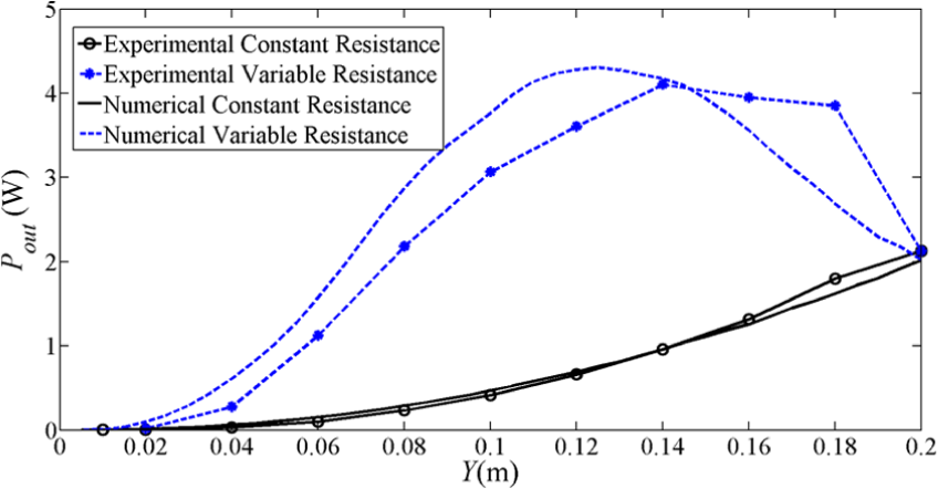
Experimentally and numerically obtained average output power with variable and constant load resistance for different excitation levels.
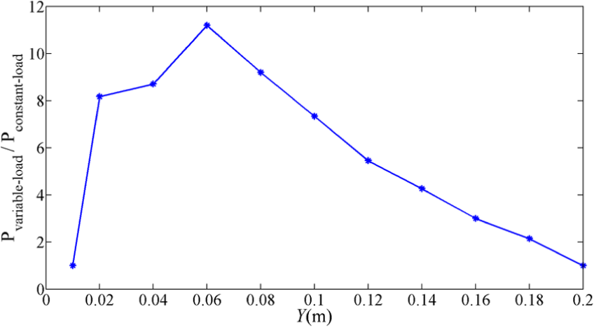
The ratio of the output power in the system with variable load resistance over the power produced by the system with constant load resistance for different levels of excitation in the experiments.
Discussion and conclusion
This article theoretically develops and then experimentally validates the idea of extending the dynamic range of a constrained energy harvester subjected to amplitude-varying excitation by utilizing a variable load resistance. The method described in this article is a crucial step towards designing a complete control solution to overcome a fundamental limitation of vibration energy harvesters when they are subjected to time-varying frequency and amplitude excitation. In the case of the rotational energy harvester presented in this article, the frequency of the device can be actively tuned by changing the moment of inertia of system, as discussed in Hendijanizadeh (2014). It is shown that when an energy harvester is subjected to the maximum level of excitation, the load resistance should be selected so that the mass throw does not exceed the constraint defined by the size of device. However, by reducing the input excitation level, the energy harvester then performs in a sub-optimum condition. To extend the dynamic range of a constraint energy harvester, a variable load resistance is introduced, so that at the lower levels of excitations, the load resistance is increased and the excitation of the harvester rises. When the system is subjected to low level of excitations, it can be treated as an unconstraint system. Its load resistance can then be tuned to match the mechanical damping of the system, which is the condition that guarantees transferring the maximum power to the load. If one selects the load resistance equal to the unconstraint applications, when the excitation level increases, the mass throw may exceed the defined constraint. Therefore, the load resistance should be decreased to increase the applied electrical damping and control the relative displacement of mass.
In order for the electrical load resistance to have a significant effect on the mechanical damping, and hence the throw, of the harvester, a strong electromechanical coupling is required. The nondimensional parameter previously introduced system in Hendijanizadeh et al. (2013a) and Elliott and Zilletti (2014) to characterize the electrical coupling, that is,
Although designing the control system is outside the scope of this article, this research can be continued by implementing a practical variable moment of inertia mechanism, as discussed in Hendijanizadeh et al. (2013a, 2013b), in combination with a variable electrical load control method, discussed in this article, to have a comprehensive system that controls both natural frequency and the throw for an autonomous robust energy harvester. To change the moment of inertia of the system, two-step motors can be employed as movable masses perpendicular to the rotational shaft of the device. Also, it is known that the voltage of the generator is a function of its rotational speed. However, based on equation (7), the rotational speed of the generator is proportional to the excitation amplitude. Hence, to design an autonomous control system, the load resistance can be scheduled on the output voltage of the generator.
Footnotes
Acknowledgements
The authors thank Dr Weidong Gong from the Human Factor Research Unit of Institute of Sound and Vibration Research (ISVR) for his help with conducting experiment.
Declaration of conflicting interests
The author(s) declared no potential conflicts of interest with respect to the research, authorship and/or publication of this article.
Funding
The author(s) disclosed receipt of the following financial support for the research, authorship, and/or publication of this article: This work was supported by the EPSRC through the ‘Engineering Nonlinearity Project’ program (Grant number EP/K003836/1).