
Abstract
Ionic polymer metal composites with a flexible large deformation have been used as biomimetic actuators and sensors in various fields. This work mainly focuses on the validation of the proposed theoretical prediction for various ionic polymer metal composite applications, such as a field needing a large resultant force, large tip deflection, or high response frequency. Such properties can be controlled by the number of layers and the thickness ratio of a multilayered ionic polymer metal composite actuator. Thus, we considered major design factors such as the number of layers and the thickness ratio in analysis of the proposed theoretical model and performed experiments to verify the static and dynamic electromechanical responses of multilayered (multimorph) ionic polymer metal composite structures acting as actuators. The relation between the polymer (Nafion) and electrode or substrate is represented by β. From this theoretical analysis, three properties were analyzed and predicted based on the Euler–Bernoulli beam theory, considering the dynamics of the ionic polymer metal composite, electrode, and bonding layers (substrate layers). The predicted results of a symmetric ionic polymer metal composite multimorph were compared with results of finite element analysis and experiments using ionic polymer metal composite multimorphs with one to five layers. Finally, this work examined how the number of layers and thickness affect the dynamic properties. This can contribute to predicting and optimally designing a multilayered ionic polymer metal composite actuator for satisfying a specific requirement.
Introduction
Although research has continued on conventional actuators such as electronic motors, hydraulic actuators, and pneumatic actuators, these have limited applicability in particular fields. In particular, the structure for small form factor (SFF)–type electromechanical systems imposes some difficulties due to design factors regarding the displacement, resultant force, and response time. Such products have motivated demand for new types of actuators. Alternative technologies as described by Hummers and Offeman (1958) include piezoelectric materials, shape memory alloys, and electroactive polymers. Of these recent advances, electroactive polymers are the least developed as suitable candidates for application to artificial muscles, biomimetics, and robotics according to Kovtyukhova and Gorchinskiy (1999), Ruiz et al. (2014), and Yeom and Oh (2009).
There have been a number of attempts (Asada et al., 1995; Li et al., 2008; Porfiri, 2008; Shahinpoor et al., 1993, 1999; Shahinpoor and Mojarrad, 2000) to gain insight into the actuation mechanisms of electroactive polymers, which are called ionic polymer metal composites (IPMCs). This is because IPMCs have novel potential with their relatively large displacement at a low operational voltage, large force-to-weight ratio, and fast response time-to-displacement ratio. In addition, IPMCs can be shaped and manipulated with ease to form specific actuators for a device depending on the fabrication process. Recently, these advantages have facilitated various feasible applications of IPMCs with other novel qualities such as durability and operation in aquatic and dry environments as stated in Kovtyukhova and Gorchinskiy (1999).
The fundamentals of IPMCs have been well-described (Bhandari et al., 2012; Jo et al., 2013; O’Halloran et al., 1994; Shahinpoor and Kim, 2001b, 2001c, 2005) in review papers for applications in robotic systems, medical devices, biomimetic systems, various actuators, transducers, and so on. The fabrication of IPMC actuators requires a thin Nafion membrane to be electrochemically (Millet et al., 1989; Takenaka et al., 1982) or mechanically (Cilingir and Papila, 2010; Shahinpoor and Kim, 2001a) plated to form an electrode pair. Electroactive polymer composite actuators were realized in the early 1990s by Shahinpoor (1992) and Oguro et al. (1993a, 1993b, 1999). In particular, Oguro et al. (1993a) demonstrated that a polyelectrolyte membrane—electrode composite where both sides of the membrane is plated chemically with platinum—quickly deforms and bends in an aqueous solution with the application of a low voltage. More recently, ongoing research on IPMC actuators has focused on enhancing their dynamic characteristics through the development of theoretical models by Pugal et al. (2008), Balakrisnan et al. (2015) for various applications by Nguyen et al. (2008), Wang et al. (2009), Choi et al. (2009), Kim et al. (2006), Cha et al. (2013), and Yang et al. (2012), Gonzales and Lumia (2015).
However, even though IPMCs are expected to be a powerful solution in various fields of macro- and micro-systems, as discussed above, there exist some significant drawbacks. They can be summarized as follows: (1) poor mechanical properties (a low generative blocking force and low stiffness), (2) short operating time in air, and (3) high cost. Some of the problems related to mechanical properties may be resolved by increasing the thickness of the polymer (Choi et al., 2009), applying an additional coating of metal (Kim et al., 2006; Oguro et al., 1999), using imidazolium-based ionic liquid (IL; Safari et al., 2015), or using IL (Bennett and Leo, 2004). However, we focused on enhancing the mechanical properties by developing a multilayered IPMC.
A multilayered actuator can overcome the inherent limitations of the unimorph IPMC actuator. Thus, optimizing unimorph, bimorph, and multimorph actuators is important to maximize the resultant force or vertical displacement at the end tip. In addition, the number of layers and the thickness ratio between the electrode and layers of the Nafion membrane or bonding layer affect the behavior of the IPMC actuator. We previously proved the optimal number and thickness ratio of piezoelectric materials and structural layers making up a multimorph to maximize the tip deflection and resultant force of the tip (Lee et al., 2005). Based on our previous work, the objective of this study was to develop a novel design guide based on analytical prediction of the end-tip displacement, natural frequency, and resultant force according to the number of structural layers of the IPMC actuator consisting of multimorphs. A theoretical model was derived that includes the dynamics of multimorphs, and it is analytically solved to predict the natural frequency and maximum displacement. In particular, the effect of the thickness ratio β (Tadmor and Kosa, 2003) of a multimorph IPMC actuator was newly analyzed according to various thickness ratios between each layer. The analytical predictions with respect to the behavior of an IPMC multimorph were verified through various experiments. These results will help in the development of new applications to overcome the inherent limitations of IPMC actuators.
Principles of the IPMC actuator
The fundamental mechanism of well-known IPMCs is as follows (O’Halloran et al., 1994; Shahinpoor and Kim, 2001b, 2001c, 2005). If a voltage is induced to the platinum electrodes at the top and bottom surfaces of the Nafion membrane, an electric field is applied across the membrane. Then, sodium ions migrate from the anode to the cathode due to the electrostatic force. When the polymer is hydrated, water travels with these ions. Thus, when one of the electrodes expands, the other electrode contracts. Consequently, a cantilever-type IPMC operates in a bending mode resulting from the applied electrical load. Figures 1 and 2 illustrate the structure and effect of IPMCs, respectively. This study used a unimorph IPMC fabricated by Environmental Robots Inc. (ERI) with dimensions of 5 mm × 30 mm × 0.2 mm.
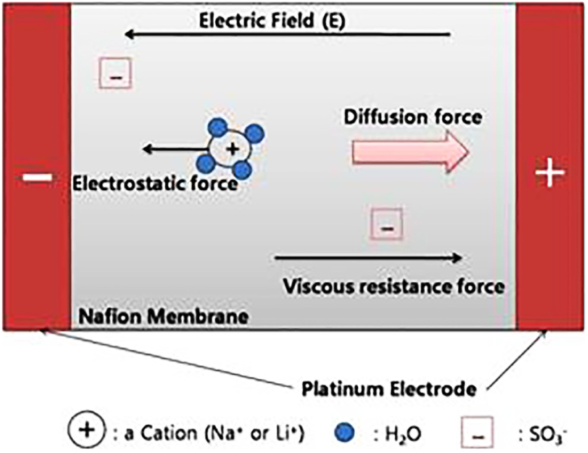
Bending mechanism of IPMC actuators.
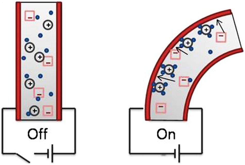
Actuation of IPMC actuators.
Principles of the IPMC actuator
Static analysis of IPMCs
The mechanical characteristics of IPMCs have previously been covered in the literature (Choi et al., 2009) In this study, a multilayered IPMC actuator was considered as an alternative to resolve the limitations of unimorph IPMCs. When an IPMC actuator consists of several unimorph layers, it can amplify both generative force and resonance frequency. However, even if previous works on cantilever-type unimorph IPMC actuators accurately predict their mechanical behavior, these results are not valid for multilayered IPMCs because of the moment generated at each IPMC layer. Thus, based on our work (Choi et al., 2009) on design variables and mechanical characteristics associated with multilayered actuator, in this study, we considered the theoretical modeling and analysis for the development of a multilayered unimorph IPMC actuator.
Figure 3 shows a unimorph IPMC actuator bonded to the top and bottom surfaces of the structure and the proposed multilayered unimorph IPMC with a symmetric structure about xy-plane. The figure does not show the bonding layer between each IPMC actuator, but the total IPMC strain is affected by the bonding layers. This effect was not considered in the previous work (Choi et al., 2009), where the thickness of the bonding layer was assumed to be zero. However, the theoretical model proposed in this work concludes that the layer in the IPMC actuator is more compliant than that of the lead zirconate titanate (PZT) actuator, as indicated in equation (1). Here, the total thickness of the IPMC actuator was assumed to be small enough for slender beam analysis when there is a strain
The plate thickness is much less than the radius of curvature induced by the electrical loading.
The cross section of the layers is constant along the length of the plate.
The xz-plane is the plane of symmetry.
The xy-plane is the neutral surface.
The plane sections remain on the same plane.
Equilibrium requires that the resultant stress distribution over the cross section of the plate be equal to the bending moment.
The stacked IPMC actuator has insulating layers between each opposed unit actuators.
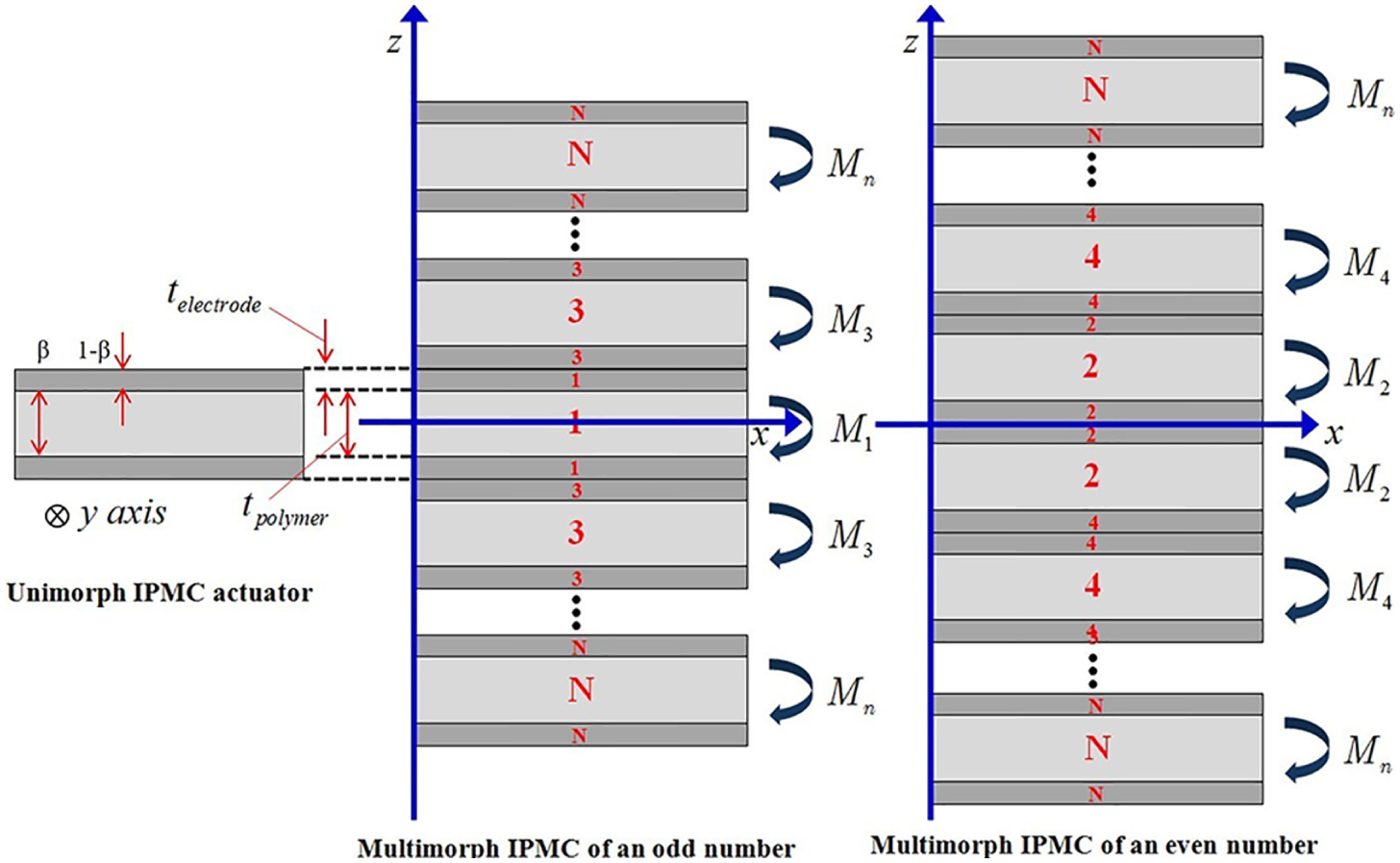
Configuration of a symmetric multilayered IPMC of a cantilevered type.
Also, we assumed that the stacked plate is perfectly bonded so that a linear motion is generated at the interface. Then, the conventional assumptions for the stress and strain distributions can be applied to this analysis as follows. The strain distributions can be expressed by

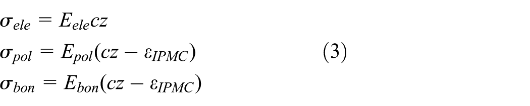
The stress distributions in the structures of a unimorph IPMC comprising an electrode and polymer can be represented by
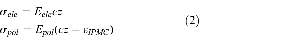
where c represents the curvature of the cantilever beam;
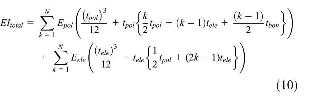
If there are no external forces and bending moments in the axial direction, the internal moment balance with respect to the neutral axis for a multilayered IPMC actuator can usually be described as
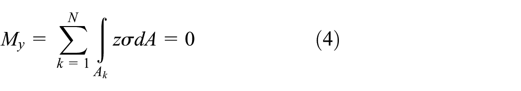
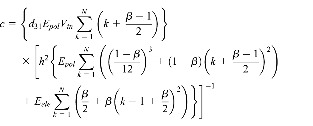
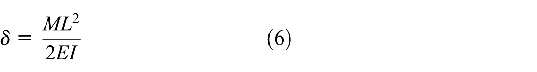
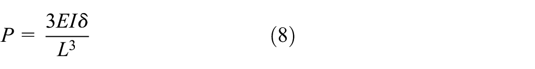
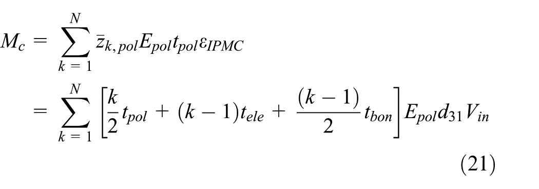
Figure 3 shows the proposed N-layer schematic of a unimorph actuator. When an electric field is applied to each electrode, the IPMC layers above the x-axis expand and the layers on the bottom side contract. The location at x = 0 is fixed, and the right end of the beam is free. Due to the strain in each IPMC layer, the multilayered bimorph actuator bends in the transverse direction. The maximum tip deflection of cantilever beam is derived as equation (6). Lee et al. (2005) have contents of expression of the maximum tip deflection of the cantilever beam using curvature of actuator instead of the momentum, elastic modulus, and inertia. Because the c (curvature), shown in equation (5), is derived with electromechanical coefficient and other mechanical (physical) properties (see equation (5)), we can adopt to IPMC theoretical modeling since IPMC has similar characteristics with piezoactuator in terms of using electromechanical properties like
where
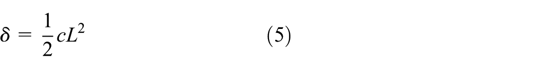
The resultant tip displacement of the IPMC multimorph actuators due to the applied voltage δ is as follows
Here, L and
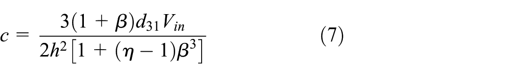
Here, h is the total height of the IPMC actuator; and
where
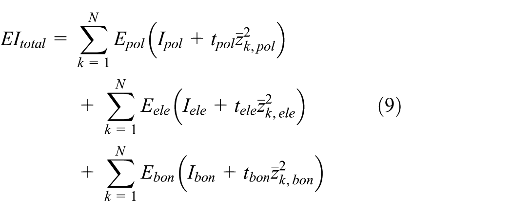
In the case of a unimorph IPMC actuator (N = 1; no bonding layer is needed)
In the case of a multimorph IPMC actuator (N ≥ 2; with bonding layers)
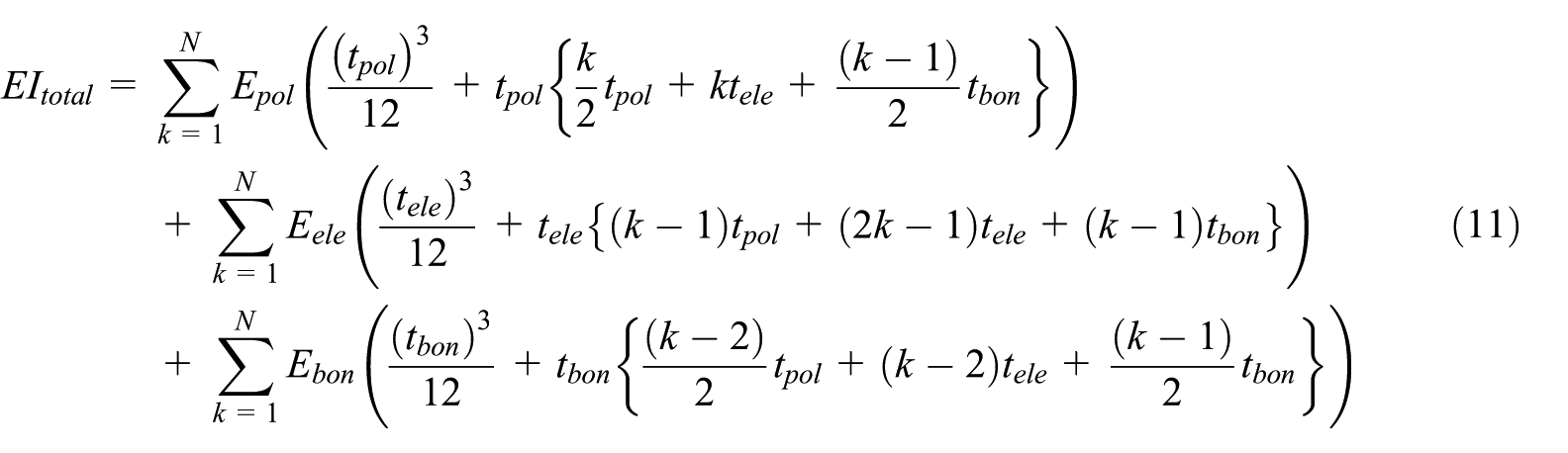
where
Dynamic analysis based on Euler beam theory
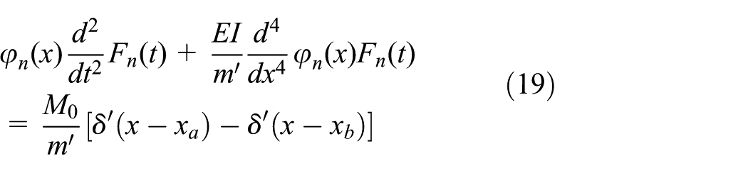
To analytically understand the dynamic properties of the multilayered IPMC actuator, we performed a dynamic analysis on the IPMC model. However, the IPMC actuator is known to have periodic nonlinear properties in general. Thus, we approximated the motion of a beam including the IPMC actuator using an Euler beam model. We also considered the mathematical modeling of a cantilever beam. The equation of motion for a cantilever beam can be represented as follows
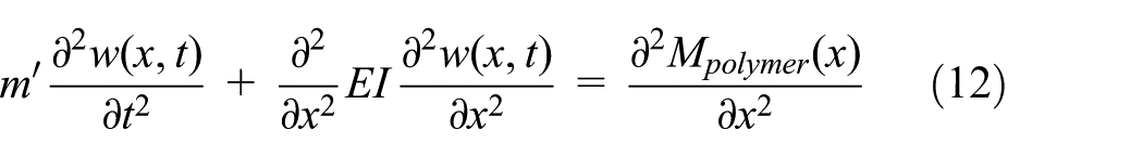
where

where only the IPMC material exists in the region between
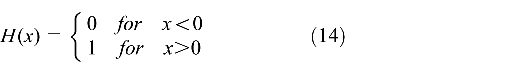
To solve the general equation (12), we represent the right-hand side of equation (12) with equation (13) as follows
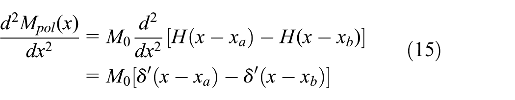
where

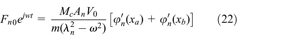
After forced response analysis of a cantilever Euler beam based on oscillating the voltage applied to the actuator, we get the following response
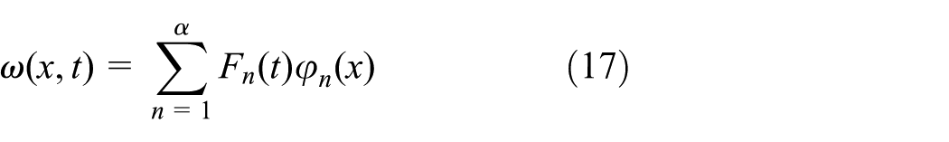
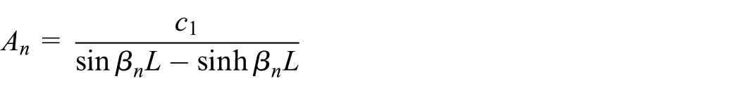
Under a harmonic motion and the applied boundary conditions, the eigenfunctions associated with individual eigenvalues can be expressed as follows
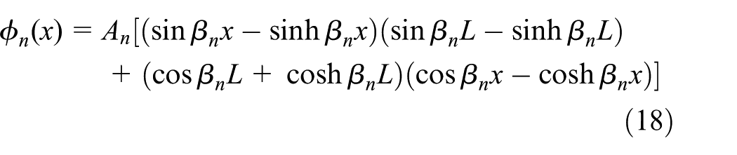
where
Then, equation (12) may be given by
Using the property of normalized mode shapes and the orthogonality of the natural modes with

where
If
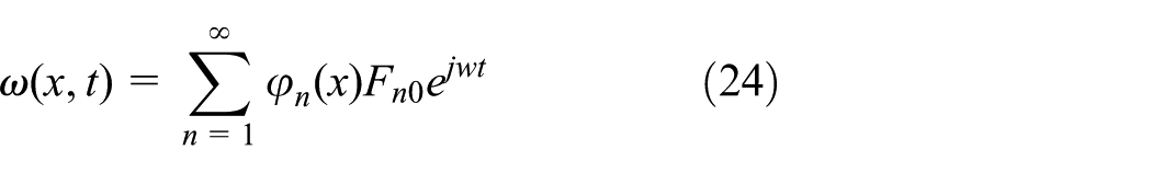
Then, equation (20) can be expressed as

Thus, by substituting equations (17) and (23) into equation (18), the general solution to the dynamic equation for the multimorph bending IPMC actuator becomes
Experimental verification with the analytical model and finite element analysis
Experimental setup
For the design of an IPMC actuator, the main considerations are the maximum displacement, generative force, and natural frequency. In order to validate the analytical results of these parameters derived in section “Principles of the IPMC actuator,” the simulation results from finite element analysis (FEA) were compared with the experimental results. Figure 4 shows a schematic of the experimental setup. The displacement was measured with an LK-H155 laser displacement sensor having a sensitivity of 0.001 µm. LK-H155 is a non-contact measurement system that senses the displacement and velocity. For the measurement, sinusoidal waveform electric fields were applied to the actuator. The measured data were collected and analyzed with a DA (Data Acquisition) board and AVR128 programmable control board. Figure 5 shows the unimorph and multilayered IPMC actuators used in the experiments.
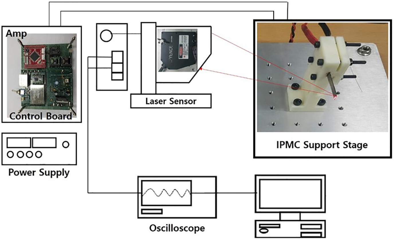
Experimental setup for actuating a cantilevered IPMC actuator (50% RH, 25).
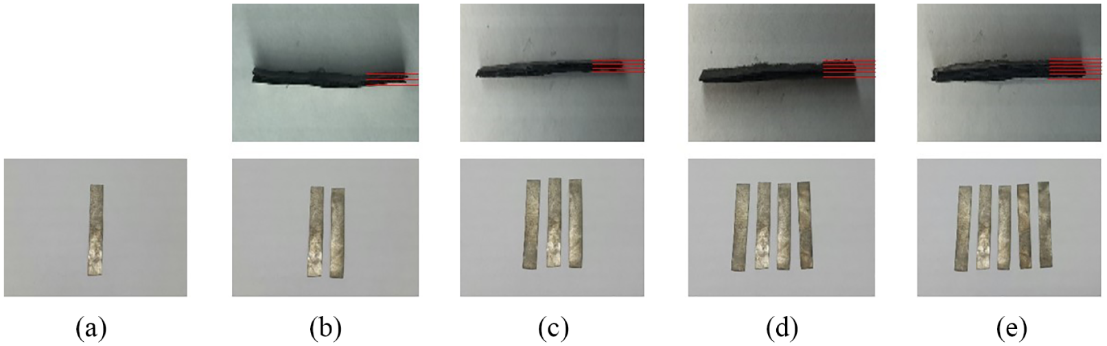
(a) Unimorph, (b) two-layered, (c) three-layered, (d) four-layered, and (e) five-layered IPMC actuators fabricated.
Experimental verification
The behavior of cantilevered IPMC actuators was verified experimentally to validate the analytical approach presented in the above section. In order to calculate the main performance indices such as the transverse displacement, first natural frequency, and output force, the required parameters E,
Parameters of IPMC material and design factor.
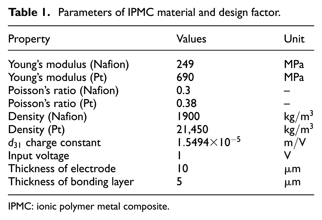
IPMC: ionic polymer metal composite.
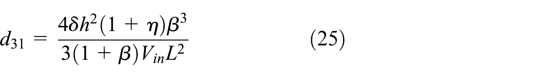
The coefficient
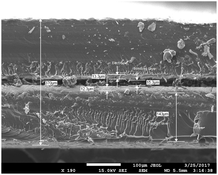
SEM micrograph of the multilayered IPMC’s cross section.
Figure 7 shows the transverse displacement of the unimorph as a function of the voltage applied across the IPMC thickness. The displacement generally increased with the applied electric field and showed a hysteretic motion. The hysteretic curve in Figure 7 is acquired when a periodic input with a voltage between −2.5 and 2.5 V was applied to the unimorph IPMC. The displacement when the applied voltage was decreased from 0 to −2.5 V was somewhat larger than when the voltage is increased from −2.5 to 0 V. The maximum displacement at the tip of the actuator was measured to be
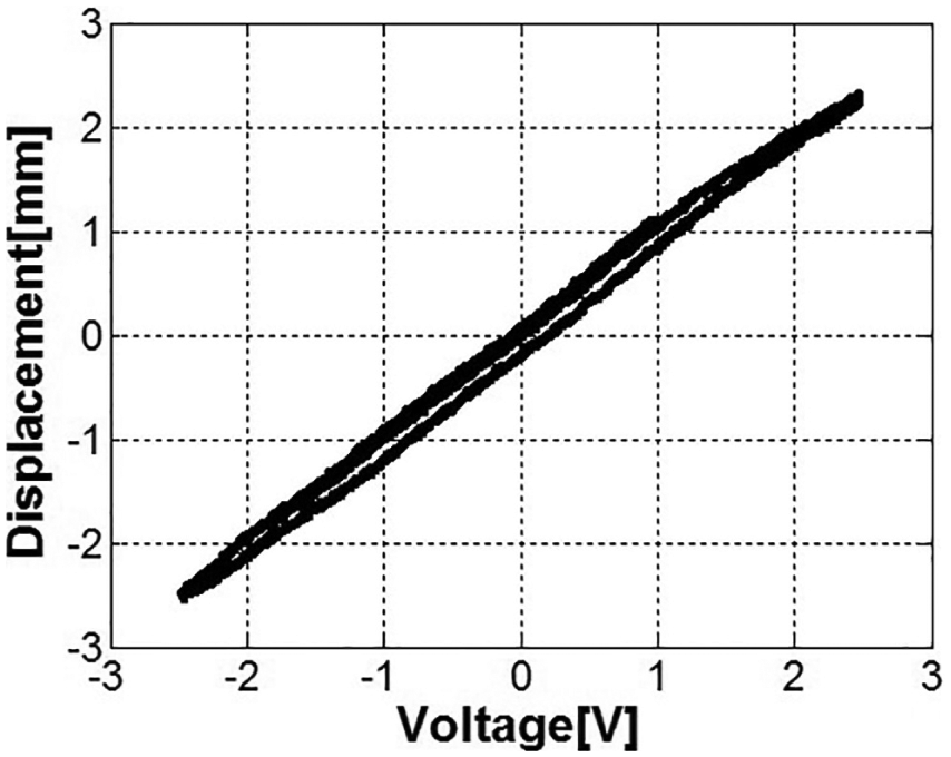
Hysteresis of the IPMCs by an electric field.
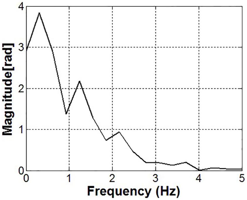
Impulse spectrum graph of the fabricated unimorph IPMC.
A perfect bonding contact (glue function) condition was applied between layered materials. Each layer was illustrated in Table 1. The solid elements are SOLID5 and SOLID45 for polymer and electrode, respectively. An auto uniform (mapped) mesh and the fixed-free boundary condition was applied to the structure of multilayered IPMC actuators. Electromechanical analysis have implemented with harmonic analysis type and its under the driving voltage of 1 V. From the results of Figures 9 and 10, the tip displacement and first natural frequency are numerically analyzed. The following three properties were used in the simulation: the compliance, IPMC coupling, and relative permittivity.
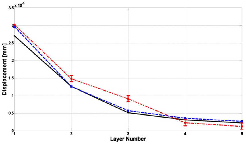
Comparison of analytical (black solid line), FEA (blue dash-dotted line), and experimental (red dash line) results on maximum displacement of multilayered IPMCs.
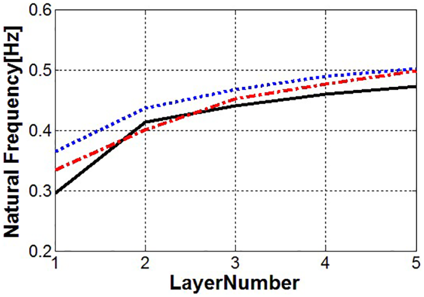
Comparison of analytical (black solid line), FEA (red dash-dotted line), and experimental (blue dotted line) results on the first natural frequency of multilayered.
Based on this, the maximum transverse displacement and natural frequency of the one- to five-layered multimorph IPMC actuators were analytically predicted and compared with the FEA and experimental results with the IPMCs (see Figure 5), as shown in Figures 9 and 10. Even though the comparison between Figures 9 and 10 indicated a valuable correlation, there was an allowable discrepancy between three results. This was due to many of factors, such as the changing boundary conditions in the experiment, inaccurate material properties, modeling-induced error, and simulation truncation error. Because the theoretical prediction agreed with the experimental results, the correlation ensured that the theoretical prediction can be employed as a design guideline for the multilayered IPMC actuator at the required number of layers (McDaid et al., 2010).
Design for various applications of IPMC multimorph
The main performance indices such as the maximum displacement, output force, and first natural frequency were optimized using the analytical approach. In total, 20 layers were used, and each unimorph actuator was 200-µm thick.
The focus of this study is understanding effect and trend from change of design parameters, such as the thickness ratio, number of layers, and thickness of each layer. So, we concentrate upon the fact description about physical movement trends as below.
Figure 11 shows the profiles of the maximum displacement at the tip, the resultant force, and the first natural frequency when the thickness of each unimorph IPMC actuator was constant at 200 µm and the total thickness of the multilayered actuator increased with the number of layers. There was no upper restriction to the resultant force as the number of layers increased. If there is no limit to the size of the actuators, the desired tip force can be obtained with multilayered IPMC actuators. However, in many cases, applications usually have dimensional restrictions. Thus, we analyzed actuators with a constant total thickness for the multilayered IPMC actuators. With a large number of layers, the tip displacement generally decreased, and the resultant force and first natural frequency increased. This agrees with our previous work (Choi et al., 2009).
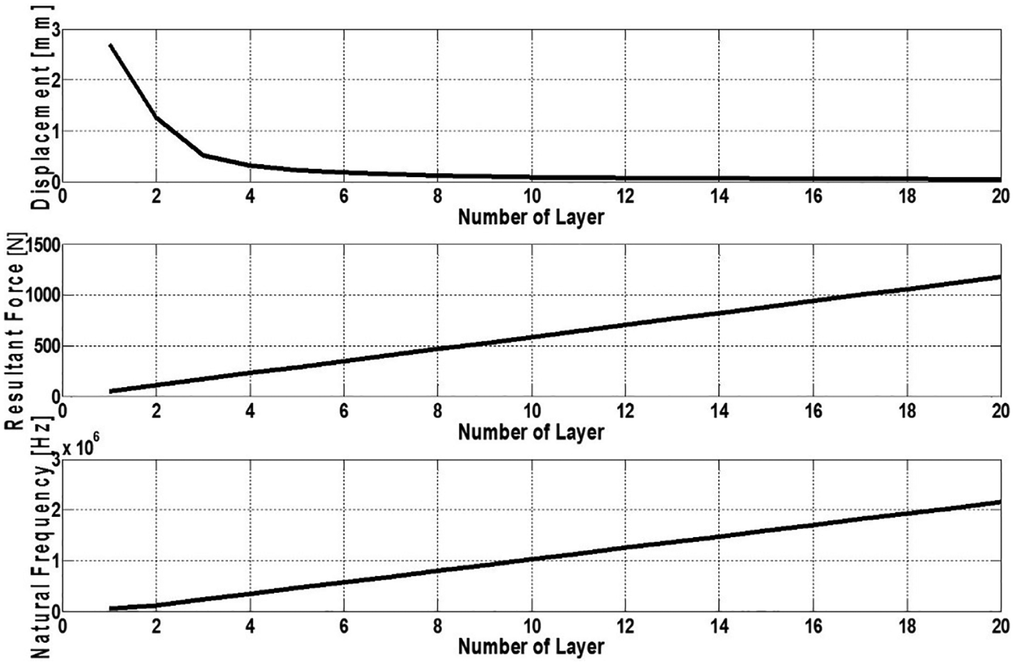
Maximum displacement, resultant force, and first natural frequency with increasing layer number and total thickness.
In contrast to Figure 11, Figure 12 shows that the tip displacement also increased with the resultant force and first natural frequency. Figure 12 shows a constant total thickness of 0.2 mm as the number of layers was increased. The thickness of the polymer layer decreased with a larger number of layers. When the thickness ratio of the bonding and electrode layers decreased, the total moment of the polymer layer had a larger effect than when the total thickness increased. This means that whether or not the thickness ratio of each constructed layer and the total thickness is constant is a significant factor for some applications in specific areas. However, the resultant force converged toward 60 Pa in this case. If there are other constructions of the IPMC actuator with a constant total thickness, the resultant force would converge to a specific value; as the number of layers increases, the total thickness of the substrate layer would be large. This is an internal constraint; both the polymer thickness and the resultant force would be small. Thus, when using a multilayered IPMC actuator with a constant total thickness, the two-layered IPMC actuator is the best choice because it dramatically improves the resultant force compared to the single-layered actuator. Hence, this should be considered for the actuator design in applications with a constant total thickness.
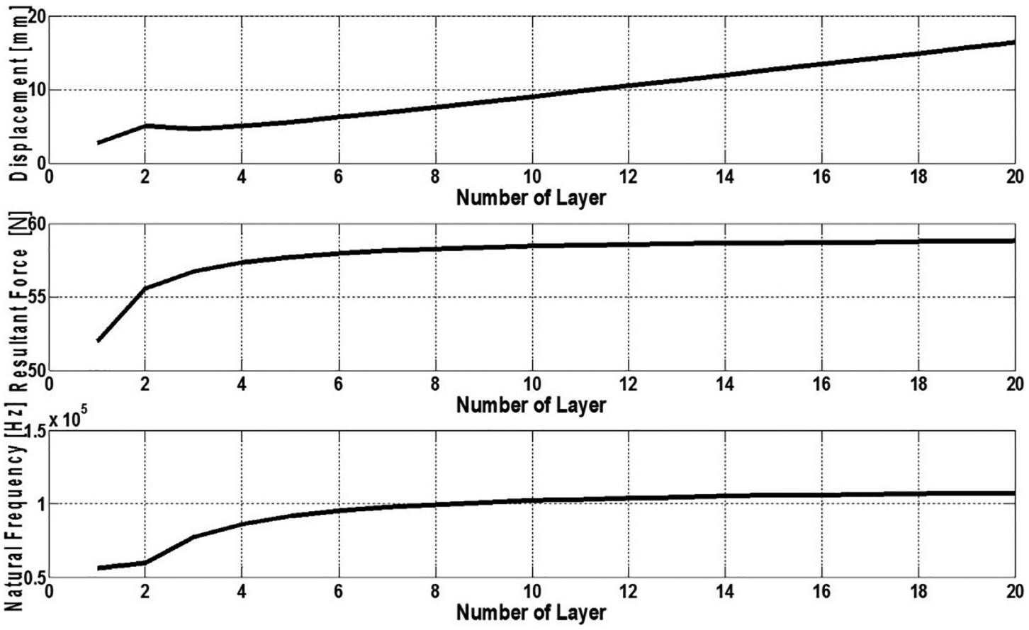
Maximum displacement, resultant force, and first natural frequency with increasing layer number and constant total thickness.
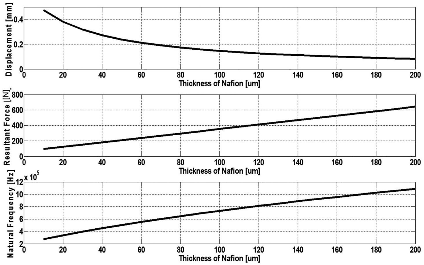
Figure 13 shows different trends of the tip displacement from the first natural frequency and the resultant force as thickness ratio of the polymer layer is increasing. When the polymer thickness is 20 µm, the tip displacement is dramatically increased against 10 µm. In this case, the total moment of the IPMC actuator by the polymer cannot overcome the stiffness of electrode since the polymer thickness is identical with the thickness of electrode. But the total moment of the IPMC actuator increased monotonously as increasing the polymer thickness ratio so that the resultant force is also increased and the first natural frequency is increased with total inertia of actuator. On the contrary, the increase in total inertia causes decrease in tip displacement.
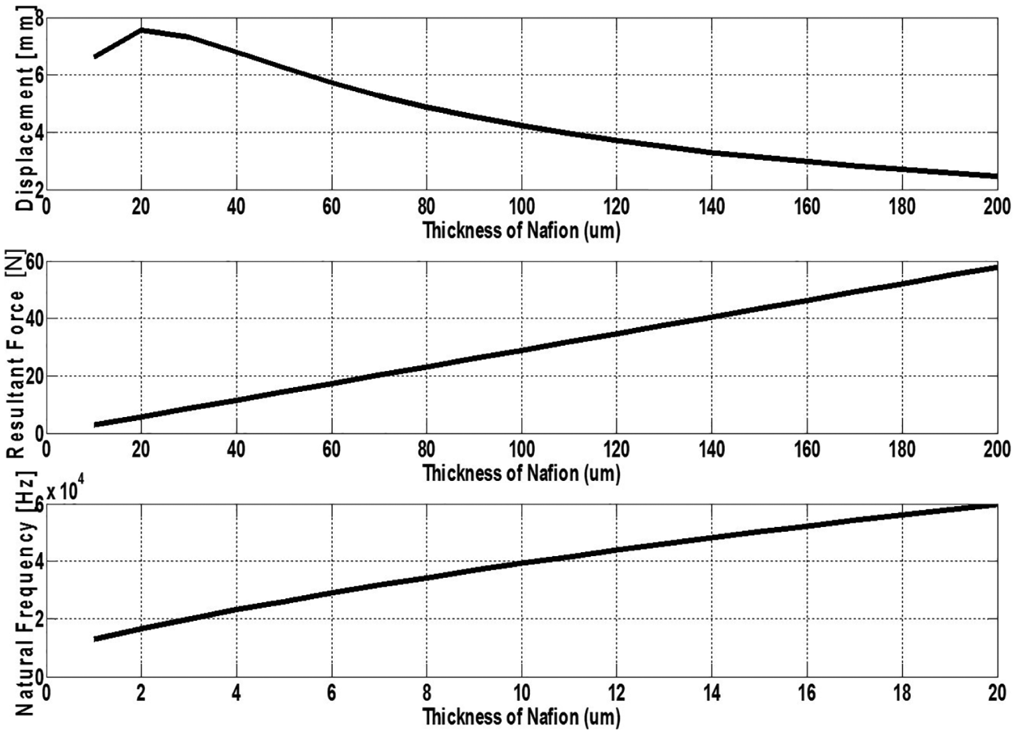
Maximum displacement, resultant force, and first natural frequency with increasing ratio of Nafion thickness.
In contrast to Figure 13, the tip displacements shown in Figures 14 and 15 decreased starting from a polymer thickness of 10 µm. Figures 14 and 15 show 10- and 20-layered IPMC actuators, respectively. Because those actuators provide a sufficient moment, they can overcome the stiffness of the electrode even when the polymer thickness is 10 µm, unlike the actuator shown in Figure 13. Even though the tip displacement was reduced because of the effect of inertia with increasing polymer thickness, adequately determining the polymer thickness when using the multilayered IPMC actuator is important below a certain substrate layer thickness because the increased margin of the tip displacement is large depending on the increase in polymer thickness with an increasing resultant force and natural frequency. From the experimental results in this study, a polymer with the same thickness as the electrode is the most appropriate. However, the trade-off between the resultant force and tip displacement must be considered in applications where the resultant force is important.
Maximum displacement, resultant force, and first natural frequency with increasing ratio of Nafion thickness when the number of layers is 10.
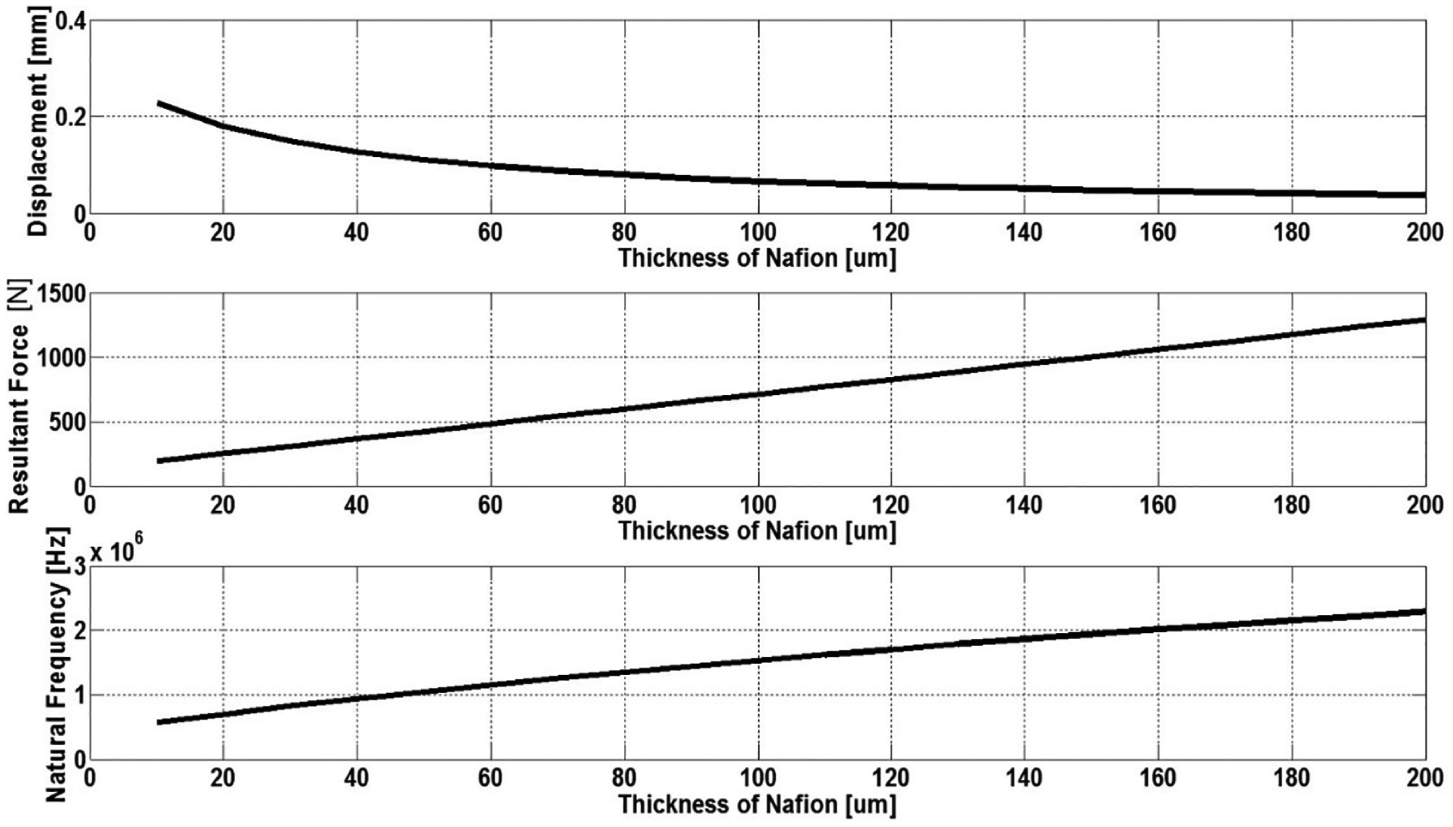
Maximum displacement, resultant force, and first natural frequency with increasing ratio of Nafion thickness when the number of layers is 20.
In contrast with the results in Figure 13, the tendency can be determined using a different electrode thickness at the same polymer thickness. When the total thickness of IPMC is not constant, the driving behavior of the actuator in the case of a variable thickness for a particular layer is identified, as shown in Figures 16 and 17. Figure 18 shows the variation in the dynamic properties according to the ratio of polymer to electrode when the total thickness was constant. As defined in section “Principles of the IPMC actuator,” the thickness ratio of the two materials was defined as β and adjusted from 0.1 to 0.9 (β was considered within the range between 0.1 and 0.9 because it is impossible to have an IPMC actuator configuration with values of 0 or 1). As shown in Figure 12, when the total thickness is constant, the driving displacement and driving force increased with the polymer ratio (β= 0.9), while the first natural frequency increased with the electrode ratio (β = 0.1), which decreased the driving displacement and driving force. Moreover, for a multilayered IPMC with more than two layers, the driving tendencies of the IPMC actuator can be identified according to the thickness of the bonding layer (Figure 17). The correlation between the theoretical and experimental results confirmed that theoretical predictions of the natural frequency, maximum displacement, and resultant force at the tip can be employed as design guidelines for the fabrication of a multilayered IPMC actuator at a specific number of layers, thickness, and thickness ratio.
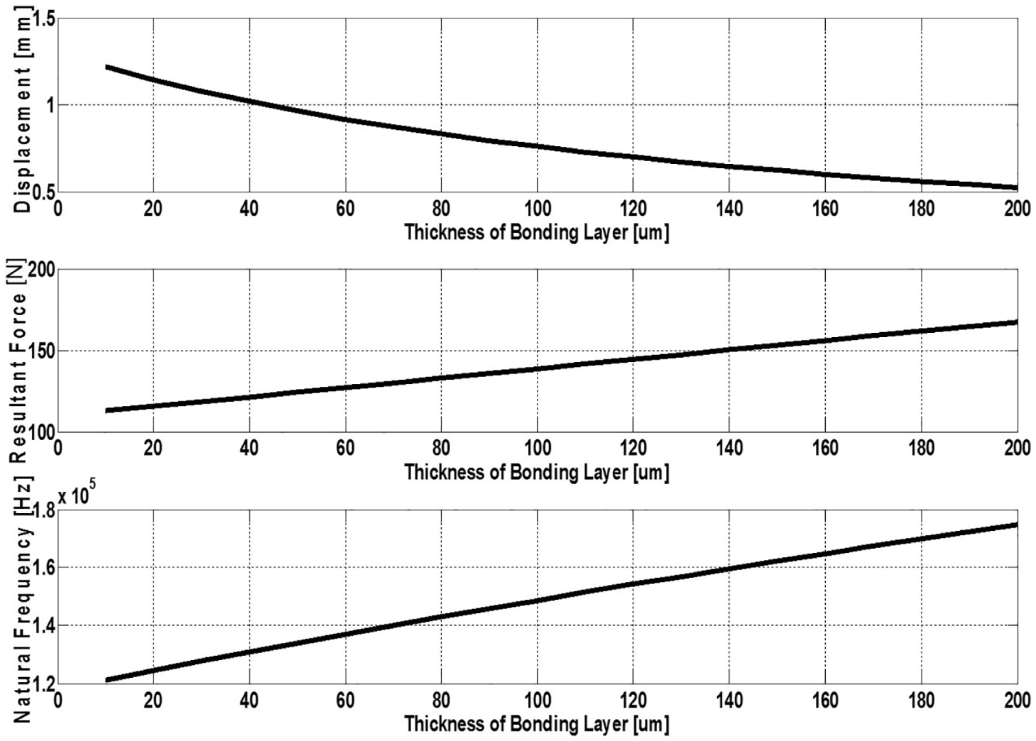
Maximum displacement, resultant force, and first natural frequency with increasing ratio of bonding layer thickness when the number of layers is two.
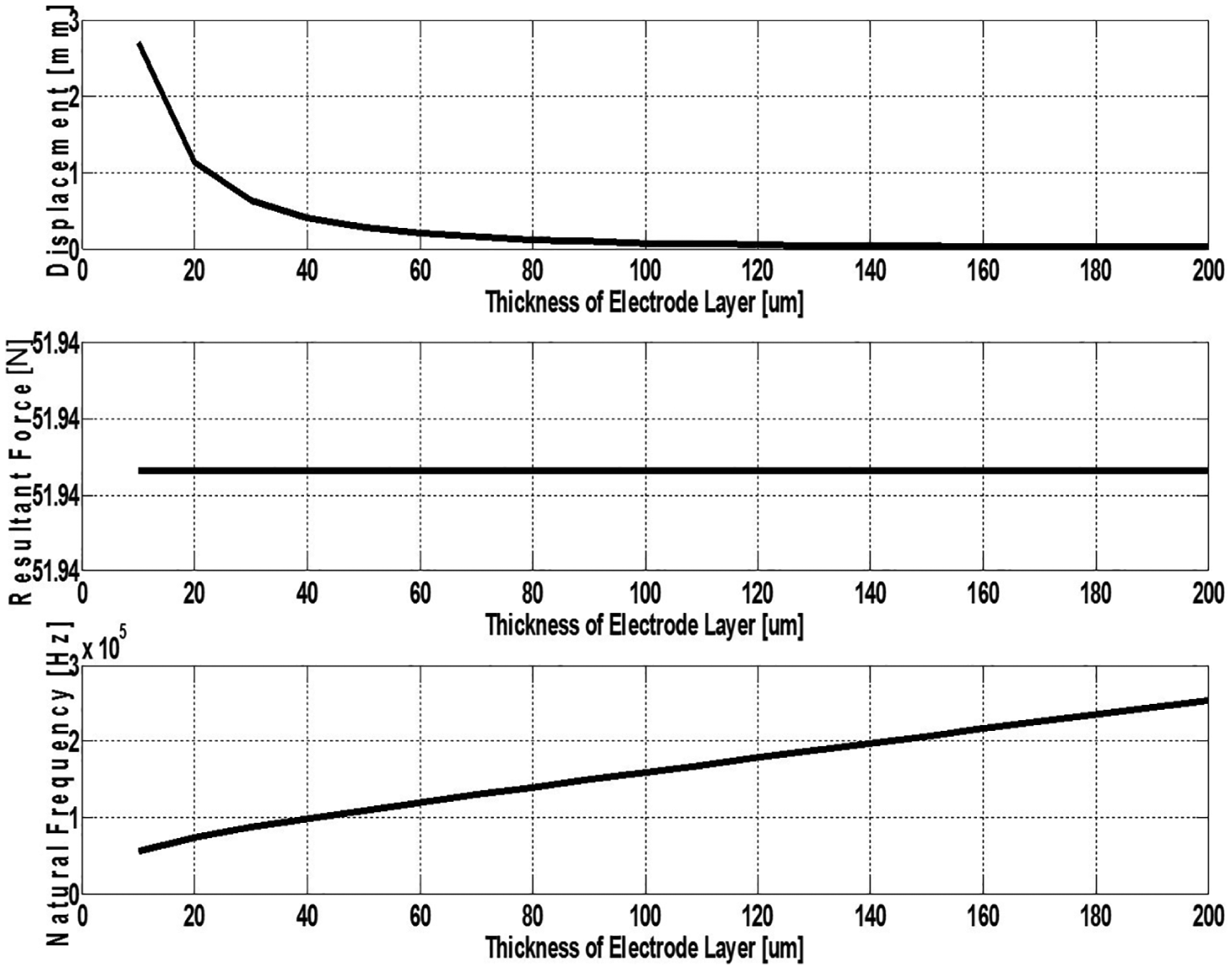
Maximum displacement, resultant force, and first natural frequency with increasing ratio of electrode layer thickness (unimorph IPMC).
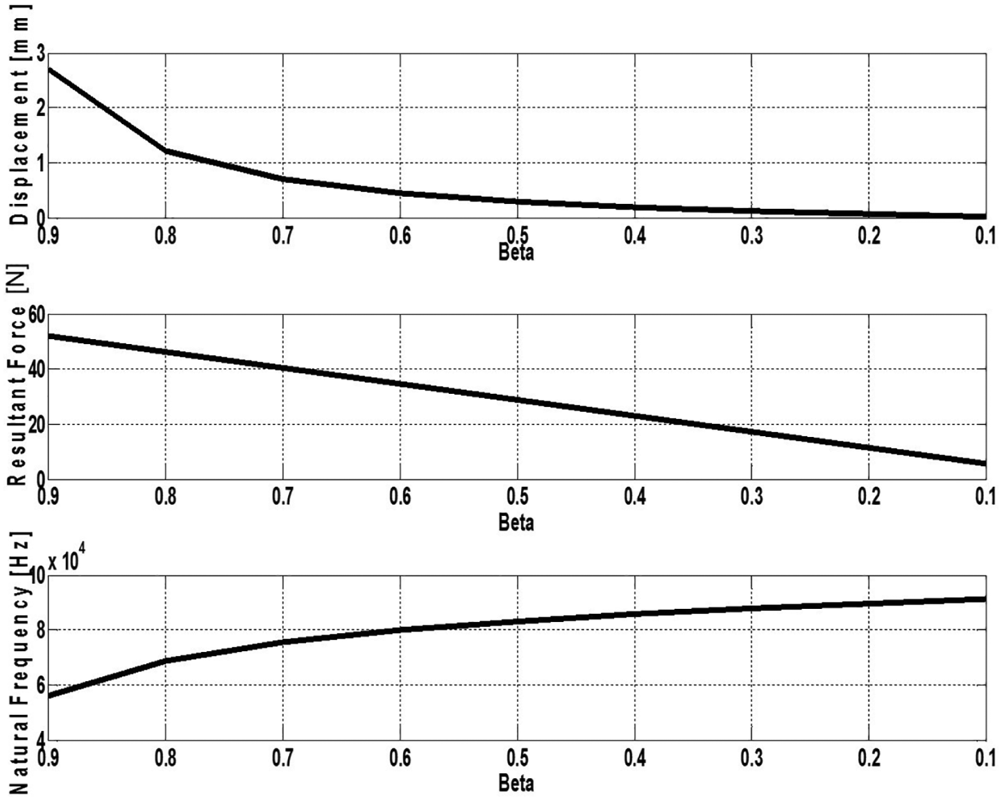
Maximum displacement, resultant force, and first natural frequency with change of thickness ratio, beta (unimorph IPMC).
Conclusion
IPMC actuators have many advantages compared with EAP (Electro Active Polymer) or other actuator types, such as a low input voltage, flexible body, and large deflection versus input voltage. However, their application is limited because of the low resultant force at the tip of single-layered IPMC actuators. In this study, the number of layers, thickness of each layer, and thickness ratio of each layer (polymer, electrode, and bonding layer) were used as major design factors for a theoretical model of a multilayered IPMC actuator. The theoretical model of the multilayered IPMC includes the dynamics of the polymer and substrate materials, and it is analytically solved to predict the first natural frequency, resultant force, and maximum displacement. Experimental results verified the analytical predictions of this theoretical model. With this, we can understand the dynamic properties depending on the number of layers, thickness, and thickness ratio of the layered materials. Thus, by controlling these design parameters, a multimorph IPMC actuator can be optimized to satisfy design requirements for new types of applications. In other words, we can calibrate the IPMC actuator properties by changing the design parameters since many application fields need various actuators and various properties for their specific needs. For various applications, the multilayered actuator makes it possible to customize the dynamic properties of IPMC actuators through controlling various design factors such as layered number, β, geometric parameters, and so on.
Footnotes
Declaration of conflicting interests
The author(s) declared no potential conflicts of interest with respect to the research, authorship, and/or publication of this article.
Funding
The author(s) disclosed receipt of the following financial support for the research, authorship, and/or publication of this article: This research was supported by the Basic Science Research Program through the National Research Foundation of Korea (NRF) funded by the Ministry of Education (2017R1A2B3010336) and by the Research Grant of Kwangwoon University in 2016.