
Abstract
This article investigates the efficiency of a new generation smart isolation system, namely shape memory alloy wire-based lead rubber bearing, for the seismic response control of long-span cable-stayed bridge systems under near-fault ground motions. The constitutive model of shape memory alloy wire-based lead rubber bearings is coded and implemented into OpenSees as a new user element. This user element can accurately predict the re-centering capability and energy dissipation capacity of shape memory alloy wire-based lead rubber bearing under different excitations. The Sutong cable-stayed bridge in China, with a main span of 1088 m, is taken as an example. Results reveal that implementing shape memory alloy wires into lead rubber bearings can effectively increase the self-centering property and, as a result, reduce the residual deformation in shape memory alloy wire-based lead rubber bearings under near-fault ground motions. Shape memory alloy wires lead to an increase in the horizontal stiffness and energy dissipation capacity of shape memory alloy wire-based lead rubber bearings. The deck displacement is restricted effectively, and a superior structural performance is achieved in terms of the deck acceleration. Shape memory alloy wire-based lead rubber bearings can effectively reduce the base shear and base moment of the towers. However, it is observed that an increase in the shape memory alloy wire diameter may have negligible effect on the deck acceleration, tower base shear and moment, and in some cases, on the pier base shear and moment.
Keywords
Introduction
In the last few decades, cable-stayed bridges have become popular structures throughout the world, due to their appealing aesthetics, full and efficient use of structural materials, fast construction, and increased stiffness compared to suspension bridges (Casciati et al., 2008; Ren and Obata, 1999). The design and construction technologies of cable-stayed bridges are also making rapid progresses. The central span of cable-stayed bridges, such as the Sutong cable-stayed bridge (SCB; 1088 m) in China and Russky Island cable-stayed bridge (1104 m) in Russia, has exceeded 1000 m. These bridges are critical lifeline facilities of local and national transportation systems. Some of them have been built in high seismic zones, and the seismic safety of such huge structures is of great concern (Chang et al., 2004).
A number of studies have focused on the seismic behavior of cable-stayed bridges under extreme dynamic loads (Ali and Abdel-Ghaffar, 1994; Li et al., 2011; Martínez-Rodrigo and Filiatrault, 2015; Shrestha, 2015; Wang et al., 2015). These studies have shown that the performance of a cable-stayed bridge depends on the mechanism by which the deck is connected to the towers. If the main deck is restrained longitudinally to the tower, it will result in reduced movement under earthquakes but will cause a significant increase in the demands on the towers in terms of bending moment and shear force. On the other hand, if the deck can move freely at the towers location, the induced seismic forces at the base of the tower will decrease significantly, but an unacceptable sliding of the deck will be seen. Therefore, some sort of relative movement between the deck and towers is beneficial to decrease the overall forces transmitted between the superstructure and the substructure. Considering the long fundamental period, large flexibility, light weight, and little structural damping characteristics, this type of structure may be quite vulnerable to vibration under severe ground motions (Martínez-Rodrigo and Filiatrault, 2015; Sharabash and Andrawes, 2009). Elastic supports are often used to restrain the displacement of main deck due to earthquake. They do not have the ability to dissipate any energy induced by the earthquake. Hence, supplementary damping devices should be introduced to improve the seismic performance of bridge system. Considering the poor energy-dissipating capacity of elastic supports, supplementary damping devices are often used to add the damping to improve the seismic performance of cable-stayed bridges. The earthquake engineering community faces new challenges to seek and develop new damping technologies that could control the seismic response of cable-stayed bridges.
In recent years, there have been significant studies on developing effective and reliable dynamic control devices including passive, semi-active, and active control systems for long-span cable-stayed bridges (Achkire and Preumont, 1996; Iemura and Pradono, 2002; Ingham et al., 1997; Shen et al., 2015; Soneji and Jangid, 2011; Warnitchai et al., 1993; Yang and Giannopoulos, 1979). Seismic base isolation is the simplest way and one of the most popular techniques used in bridge systems. There are various types of bridge isolators, such as high damping rubber bearing (HDRB), lead rubber bearing (LRB), friction pendulum bearing (FPB), and steel plate dampers, that have been developed, tested, and used all over the world (Alam et al., 2012; Bhuiyan and Alam, 2012; Ghobarah and Ali, 2011; Warn and Whittaker, 2004). Due to the known limitations of these devices, such as aging and durability (e.g. rubber-based dampers), maintenance (e.g. viscous fluid dampers), long-term reliability (e.g. friction dampers), temperature-dependent mechanical performance (e.g. rubber-based dampers, viscoelastic dampers), instability due to large deformations (e.g. rubber-based dampers), and geometry restoration after a strong earthquake (for most dampers) (Hedayati Dezfuli and Alam, 2013b, 2014), several researchers have proposed different types of smart isolation devices equipped with shape memory alloy (SMA). SMAs have been used in the form of bar (Alam et al., 2012; Bhuiyan and Alam, 2012; Desroches and Delemont, 2002; Wilde et al., 2000), wire (Attanasi et al., 2009; Bhuiyan and Alam, 2013; Choi et al., 2005; Hedayati Dezfuli and Alam, 2013a, 2013b, 2014, 2015; Mishra et al., 2015; Ozbulut and Hurlebaus, 2010a, 2010b; Xue and Li, 2007), strand (Liu et al., 2008), or spring (Attanasi and Auricchio, 2011) to overcome several of these problems. The effectiveness of these devices has been validated through numerical analyses. In recent studies, Hedayati Dezfuli and Alam (2013b, 2015) performed numerical analyses on SMA-based elastomeric isolators considering different arrangements of SMA wires. Considering the importance of implementing SMA-based isolators in bridge systems, Hedayati Dezfuli and Alam (2015) developed a constitutive model for SMA-LRBs having double cross wires. They showed that the constitutive model is capable of accurately predicting the shear hysteretic response of SMA-LRBs for unidirectional cases. However, the seismic performance of bridges isolated by such SMA-LRBs has not been investigated based on the developed constitutive model. Therefore, it is of great interest to implement the proposed hysteresis model and evaluate the seismic response of isolated bridge structures. Extensive research work is necessary to be done on the effectiveness of using SMA-based smart elastomeric isolators to systematically provide technical data on the performance of such devices.
Near-fault ground motions possess some distinct characteristics that can have notable consequences on the structural response, especially for long-period structures (Bray and Rodriguez-Marek, 2004; Iervolino et al., 2012; Mortezaei and Ronagh, 2013; Psycharis et al., 2013; Sehhati et al., 2011). Unlike far-field ground motions, the structure can dissipate the energy in few large displacement excursions under near-fault records. This is because most of the seismic energy in near-fault records arrives in a long-period velocity pulse associated with forward-directivity effect or fling-step effect (Liossatou and Fardis, 2016; Somerville et al., 1997). It is important to note that the near-fault ground motion with pulse-type effects can contain long-period pulse-like velocity waveform and high peak ground velocities. The pulse periods of such records are very close to the periods of long-span cable-stayed bridges, for example, the pulse period of TCU068 (Chi-Chi earthquake, 1999) exceeds 12 s, and the fundamental period of SCB, used in this study, is about 16 s; it is understood that the near-fault records like TCU068 will have a significant influence on the seismic response of SCB. This kind of records can result in a seismic response of long-period structures which is significantly greater than that due to a typical far-field record or a near-fault record with non-pulse components (Ghahari et al., 2010; Sehhati et al., 2011; Vafaei and Eskandari, 2015; Zhang and Wang, 2013). There is limited works on the use of seismic isolation on cable-stayed bridges considering near-fault effect. Wesolowsky and Wilson (2003) evaluated the efficacy of using lead rubber bearing seismic isolators to influence the performance of cable-stayed bridges subjected to near-field earthquake ground motions. This study showed that seismic isolation is beneficial in reducing seismic accelerations and forces, but a large residual deformation may occur under strong earthquakes. The recent work of Ismail and Casas (2014) investigated the seismic performance of a roll-n-cage (RNC) isolator, considering the cable-stayed Bill Emerson Memorial Bridge in Missouri. The results revealed that RNC isolator is a convenient isolation system for protection of cable-stayed bridges against near-fault earthquakes, but this system may have difficulty in manufacturing and maintenance. Considering the importance of long-period lifeline structures, it is necessary to conduct extensive research on developing new damping technologies (e.g. SMA-LRB) and evaluating the performance of seismic isolation implemented in long-span cable-stayed bridge systems.
Recently, Hedayati Dezfuli and Alam (2017a, 2016) assessed the seismic fragility of a highway steel-girder bridge equipped with different steel-reinforced elastomeric isolators and SMA wire-based smart elastomeric isolators. The reliability of SMA wire-based rubber bearings in isolating highway bridges has been thoroughly investigated. However, the hysteretic behavior of such bearings was idealized using a bilinear model, which cannot fully represent the self-centering characteristics of SMA-LRBs. Hence, in this study, SMA-LRBs with a double cross configuration of wires (DCSMA-LRBs), proposed by Hedayati Dezfuli and Alam (2015), are designed and installed between towers (piers) and deck on a long-span cable-stayed bridge to reduce structural responses under near-fault ground motions. First, the constitutive model developed by Hedayati Dezfuli and Alam (2015) is coded and implemented in the finite element (FE)-based structural software, OpenSees. Then, four FE models of the SCB, which is the second-longest cable-stayed bridge in the world with a main span of 1088 m, as a case study, are generated in OpenSees by considering different connection mechanisms between pier/tower and deck. The models include rigid system (RS), floating system (FS), bridge equipped with LRBs (LRBS), and bridge equipped with SMA-LRBs (SMA-LRBS). Finally, the efficiency of SMA-LRB is investigated for the longitudinal seismic response control of the bridge in terms of (1) peak deck displacements and absolute accelerations, (2) bearing residual deformation, (3) performance improvement in the SMA-LRB compared to the LRB, and (4) internal forces in the bridge towers and piers.
SMA-LRB
Considering advantages of SMA-based smart rubber bearings such as stability, re-centering capability, high-energy dissipation capacity, and long service life (Hedayati Dezfuli and Alam, 2014), it is of great interest to implement such isolators in bridge structures. In the present study, a new generation of smart elastomeric isolators, SMA-LRB (see Figure 1), proposed by Hedayati Dezfuli and Alam (2015), is implemented in a cable-stayed bridge. The isolation system consists of two parts: LRB and double cross configuration of SMA wires (DC-SMAW). Based on the superposition method, a constitutive model for SMA-LRBs was proposed. In the model, the behavior of LRB was idealized using the bilinear model with the kinematic hardening law characterized by initial stiffness, K0, yield force, Fy, and post-yield hardening ratio, r. Note that in reality, SMA wires may experience plastic deformation at the connection of steel hook due to stress concentration. In order to reduce the stress level, a pulley within steel hook (see Figure 1) is designed and used. The pulley can turn around the steel hooks freely. The SMA wires, passed through the pulley, can avoid plastic deformation or failure.
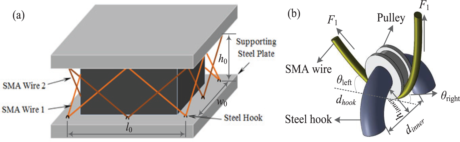
a) Lead rubber bearing equipped with double cross SMA wires (SMA-LRB), and b) SMA wire running over pulley and passing through steel hook.
As illustrated in Figure 2, the constitutive model of DC-SMAW has zero residual deformation and is characterized using three stiffnesses: primary or initial (K0,w), secondary or intermediate (Ki), and tertiary or re-centering. This model, which represents the variation of shear force versus shear deformation in the horizontal direction, is different from the flag-shaped hysteresis of SMA wire. It is because of the resultant forces of SMA material transferred to the bearing by considering the symmetric double cross configuration of wires. The stiffnesses, i.e. K0,w, Ki, and Kr, are calculated from the geometry of the bearing (length, width, and height of the laminated pad), and diameter, and material properties of SMA wires listed in Table 1. More details can be found in Hedayati Dezfuli and Alam (2015).
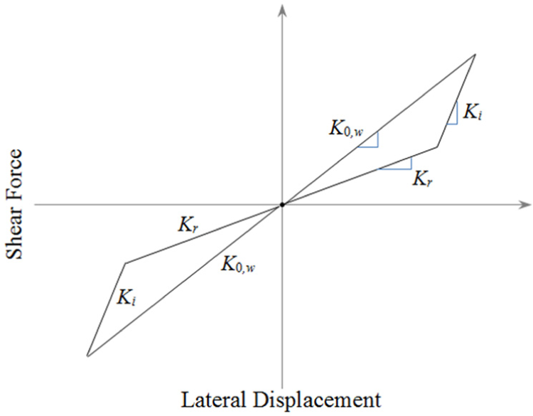
Typical hysteresis model of DC-SMAW (adapted from Hedayati Dezfuli and Alam (2015)).
Properties of the LRB and SMA wire.
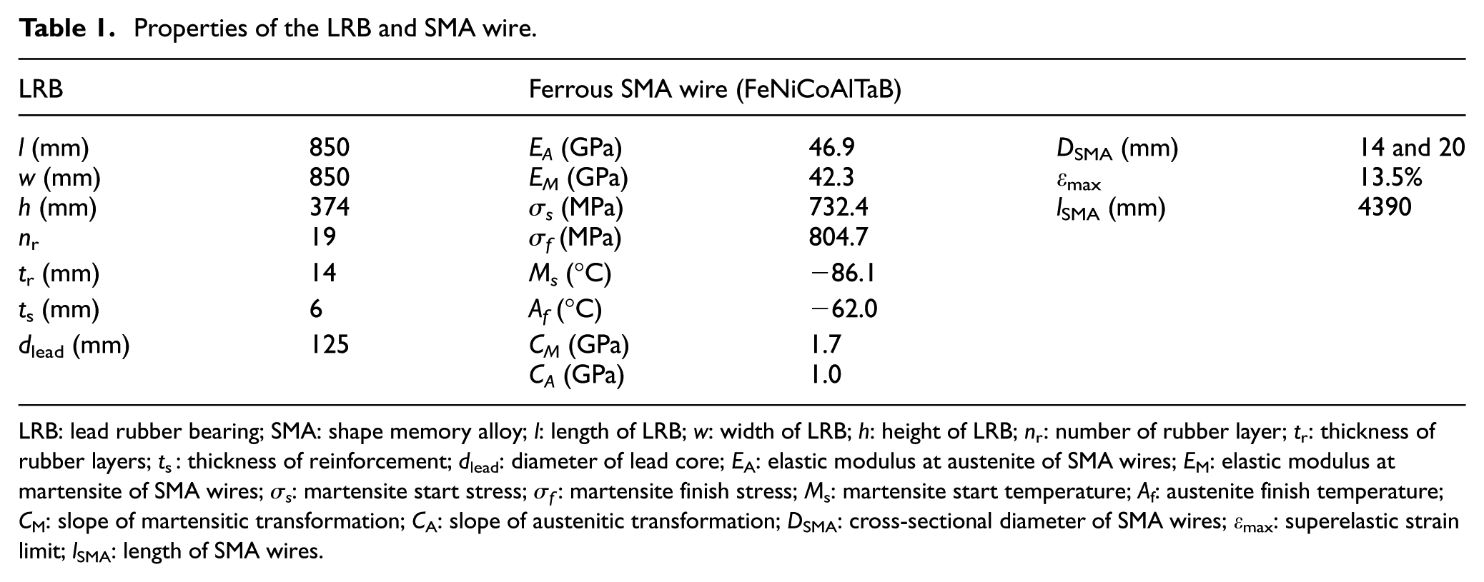
LRB: lead rubber bearing; SMA: shape memory alloy; l: length of LRB; w: width of LRB; h: height of LRB; nr: number of rubber layer; tr: thickness of rubber layers; ts: thickness of reinforcement; dlead: diameter of lead core; EA: elastic modulus at austenite of SMA wires; EM: elastic modulus at martensite of SMA wires; σs: martensite start stress; σf: martensite finish stress; Ms: martensite start temperature; Af: austenite finish temperature; CM: slope of martensitic transformation; CA: slope of austenitic transformation; DSMA: cross-sectional diameter of SMA wires; εmax: superelastic strain limit; lSMA: length of SMA wires.
Here, it should be mentioned that the model of DC-SMAW has been derived based on the idealized stress–strain model of SMA proposed by Auricchio (2001). The fatigue behavior of SMA is not taken into account in the model. The fatigue behavior of SMA wires used in base isolation systems is an important property, and several factors including alloy composition, temperature, and surface quality affect this behavior. According to the studies of Alam et al. (2007), Dolce and Cardone (2001), and Soong and Dargush (1997), superelastic SMAs have excellent fatigue resistance and are used in a wide range of seismic applications. Also, due to the excellent superelastic behavior of SMA which makes it different from other alloys, the effect of creep is neglected and it is assumed that the SMA wires are always under tension. Since SMA materials have thermo-mechanical behavior, the change of temperature affects the response of SMAs. Here, the idealized stress–strain curve of FeNiCoAlTaB, as a ferrous SMA material, at room temperature is used (Tanaka et al., 2010). In this study, the austenite finish temperature of such SMA is −62°C (as listed in Table 1). Since the working temperature is considered above this limit, it is assumed that the temperature change in SMA wires has negligible effect on its superelastic response. The detailed procedure can be found in the reference (Hedayati Dezfuli and Alam, 2015).
Due to the lack of a constitutive model in structural finite element software such as SAP2000 (SAP2000, 2000), Seismostruct (v6.5; SeismoSoft, Inc., 2014), or OpenSees (McKenna et al., 2000) which can accurately capture the actual shear hysteretic response of SMA-LRBs under seismic loading, it is necessary to develop a new user element which can work on a FE platform. Therefore, in this study, the constitutive model of SMA-LRB developed by Hedayati Dezfuli and Alam (2015) is implemented in OpenSees as two separate user elements for LRB and DC-SMAW.
To ensure that the new elements are working properly in any condition, the results, which are attained from the OpenSees, are compared with those obtained by Hedayati Dezfuli and Alam (2015) for various excitations such as ramp, step, sinusoidal, and a combination of them with different peak amplitudes. Hedayati Dezfuli and Alam (2015) attained the results from a developed computer code written in MATLAB (MathWorks, Inc., n.d.) and also verified the results in FE software ANSYS. In this study, the same code has been rewritten in C++ in order to implement it in OpenSees and use the constitutive model in seismic performance evaluation of a bridge structure. Three excitations (E1, E2, and E3) are chosen as input displacements and plotted in Figure 3. Note that the selected excitations are same as those used by Hedayati Dezfuli and Alam (2015). The geometric and material properties of LRB and SMA wires (Ferrous SMA, FeNiCoAlTaB, with a cross-sectional diameter of 5.0 mm) are the same as those used by Hedayati Dezfuli and Alam (2015). The comparison in Figure 4 shows a good agreement between the two approaches and reveals that the new elements developed in OpenSees are capable of accurately predicting the re-centering property and energy dissipation capacity of SMA-LRB under different excitations.
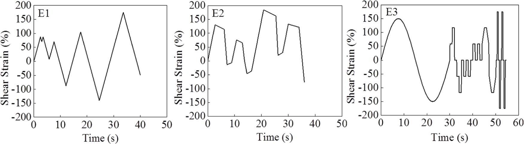
Normalized input displacement.
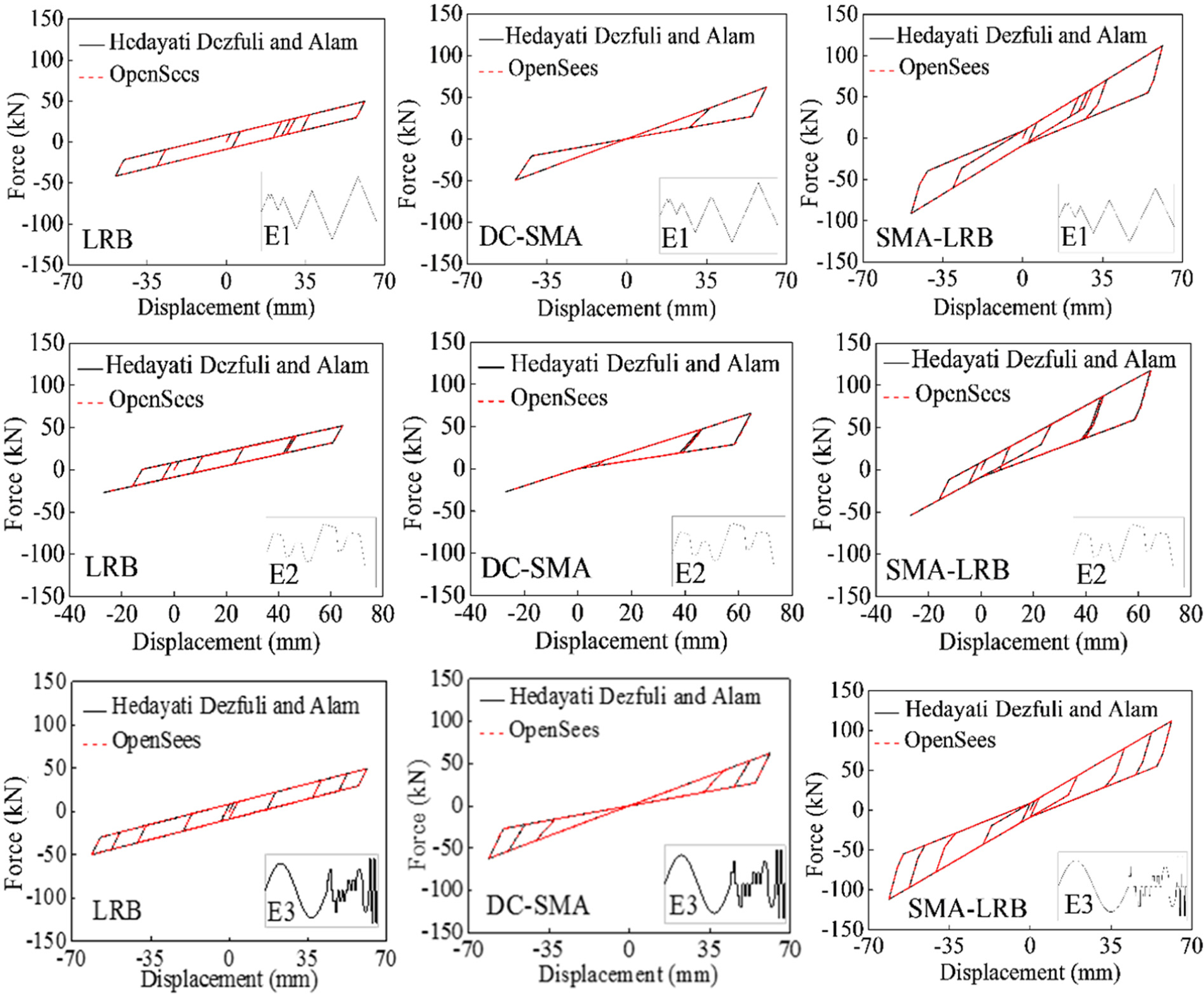
Comparison between responses of LRB and DC-SMA obtained by Hedayati Dezfuli and Alam (2015) and those obtained from OpenSees.
Cable-stayed bridge
Bridge description
The bridge model used in this study is the SCB connecting Suzhou and Nantong Cities in China. This bridge is the second-longest cable-stayed bridge in the world, with a central span of 1088 m. The bridge consists of two inverted-Y pylons with a height of 300.4 m, double plane fan configuration cables (totally 272 cable members), a streamlined flat steel box girder having a width of 41.0 m, and one transition pier and two auxiliary piers in each side span. The cable members are spaced at 2 m at the upper part of the tower and equally spaced at 16 m at the deck level on the side as well as main spans. The configuration of the bridge is presented schematically in Figure 5.
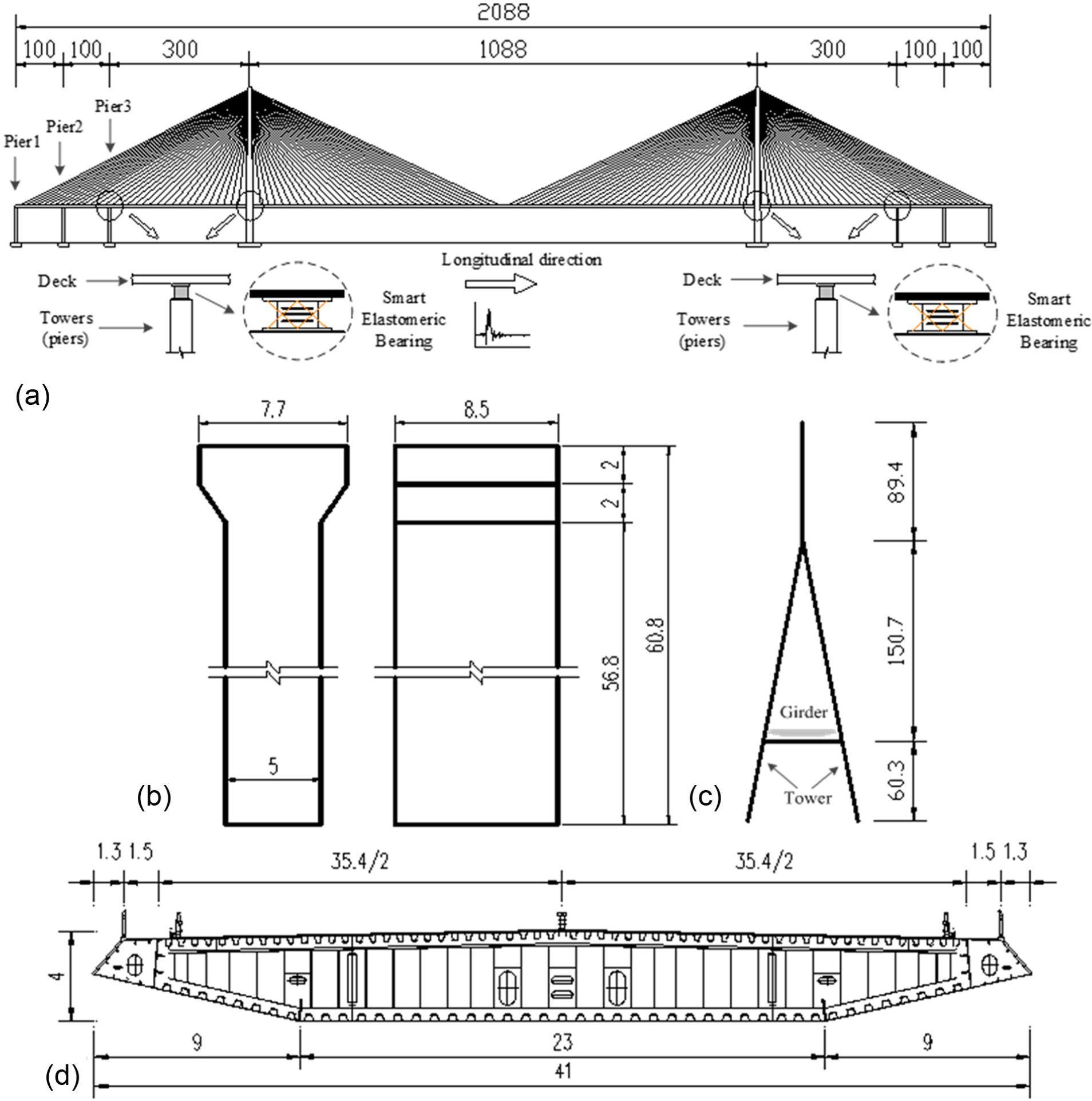
Detailed configuration of the SCB (meters): (a) longitudinal view of the bridge, (b) longitudinal and transverse views of the piers, (c) transverse views of the towers, and (d) transverse section of the deck.
The objective of this study is to verify the effectiveness of the new smart isolation bearing for cable-stayed bridge system. Hence, the existed isolated system in the as-built bridge is not considered in this study. The new isolated system, that is, LRB and SMA-LRB, is designed and used in the case study. Two types of seismic isolators are installed in this bridge, namely LRBs and SMA-LRBs. In order to design the LRBs for SCB, a design code for LRB is used based on the recommendation from American Association of State Highways and Transportation Officials (AASHTO, 2014) and Earthquake Engineering Handbook (Scawthorn and Chen, 2003). The LRBs are designed by the following step-by-step procedure: (1) the design shear strain and effective damping ratio for the bearings and the design period for the isolated structure are selected; (2) the effective horizontal stiffness and maximum horizontal displacement of the bearing are calculated using the static analysis; (3) the height of rubber layers can be calculated according to the design displacement and shear strain; (4) the design cross-sectional area and diameter of lead core can be determined based on the short-term yield force and yield force of the lead plug; (5) the design cross-sectional area of individual layers is determined. In this step, the design cross-sectional area is the maximum among three effective cross-sectional areas, that is, A0 is calculated based on the allowable axial stress, A1 is determined from the shear strain due to the vertical load, and A2 is calculated according to the shear failure of the bearing; (6) the thickness of individual rubber layer and the number of rubber layers are determined based on the shape factor of the rubber layer; (7) the steel place thickness is determined; (8) the shear strain condition for normal load case and stability of the bearings are checked.
A total of 54 isolators are arranged along the longitudinal direction, including three and nine isolators at each pier and tower location, respectively. To simplify the design procedure, the bearings installed in piers and towers are considered to be the same (see Figure 6).
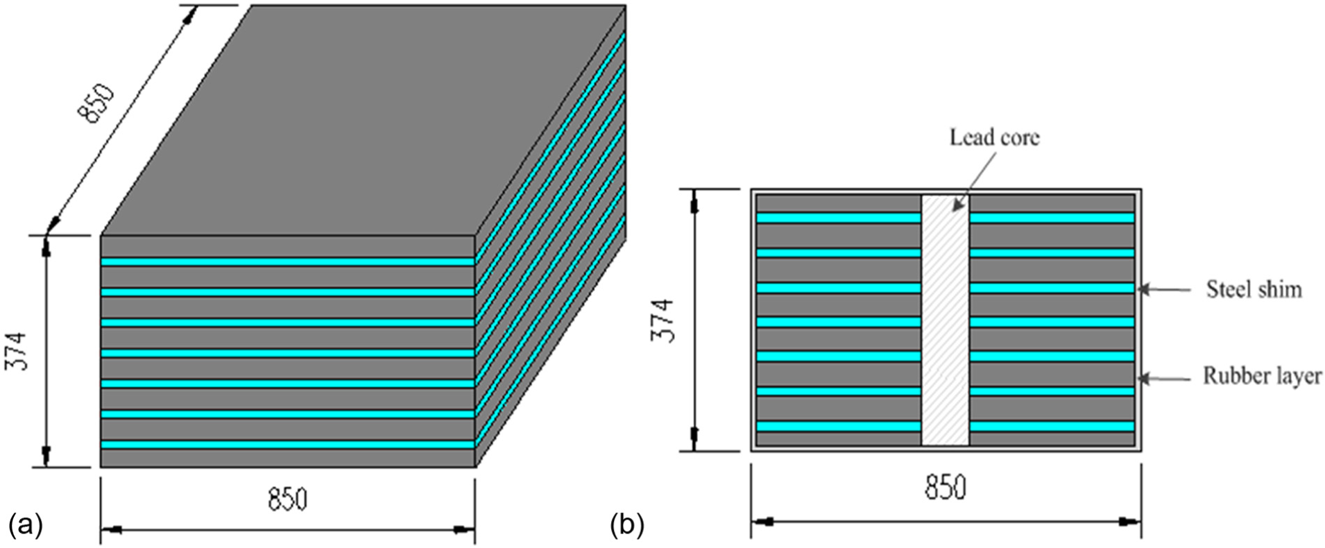
Schematic view of the LRB used in the SCB (dimensions are in millimeter): (a) LRB and (b) elevation view of LRB.
In the case of SMA-LRBS, the dimension of LRBs is same with that of LRBS. An important point for designing the SMA-LRBs is that under a cyclic excitation, if the generated resultant force in SMA wires is smaller than the maximum shear force of LRB, the superelastic property (flag-shape hysteresis) of SMA cannot noticeably affect the hysteretic response of bearing toward a performance improvement, and as a result, SMA wires will not be beneficial. Therefore, in order to make the SMA wire effective, the SMA-LRB should be properly designed by determining an appropriate dimension for the wires. The following procedure is used to determine the diameter of SMA wires (see Figure 7). An initial diameter (D0 = 2 mm) is chosen and the shear force–displacement curve of SMA-LRB is obtained under a given excitation (e.g. E3). Then, the diameter of SMA wires increases from the initial diameter until the generated force in SMA wires is nearly same as the peak shear force of LRB. Finally, the diameter of SMA wires is chosen as 14 mm. In this study, a larger diameter of SMA wire (20 mm) is also selected in order to assess the effect of wire’s dimension on the seismic performance of SMA-LRB. It should be noted that the length of wire in actual design of the SMA-LRB can be calculated from equation (1). Here, the same authors (Hedayati Dezfuli and Alam, 2017b) have proposed two different ways to install SMA wires to LRB: (1) first, SMA wires are wrapped around the LRB by passing through the steel hooks mounted on the steel end plates. Then, they are post-tensioned to avoid the slack condition of SMA wires due to the dead load of the superstructure. An adjustable mechanism for fixing the SMA wires is used to apply the force. The detail of the device can be found in Hedayati Dezfuli and Alam (2014). Finally, the SMA-LRB is placed and fixed in the required location. (2) First, the LRB is placed and fixed in the required location. Then, the SMA wires are mounted on the bearing. Ends of the SMA wires are also fixed by the adjustable mechanism. In the second approach, the SMA wires are non-pre-strained since they are mounted on the bearing after the LRB is being placed. The physical and material properties of the LRB and SMA wire are listed in Table 1.
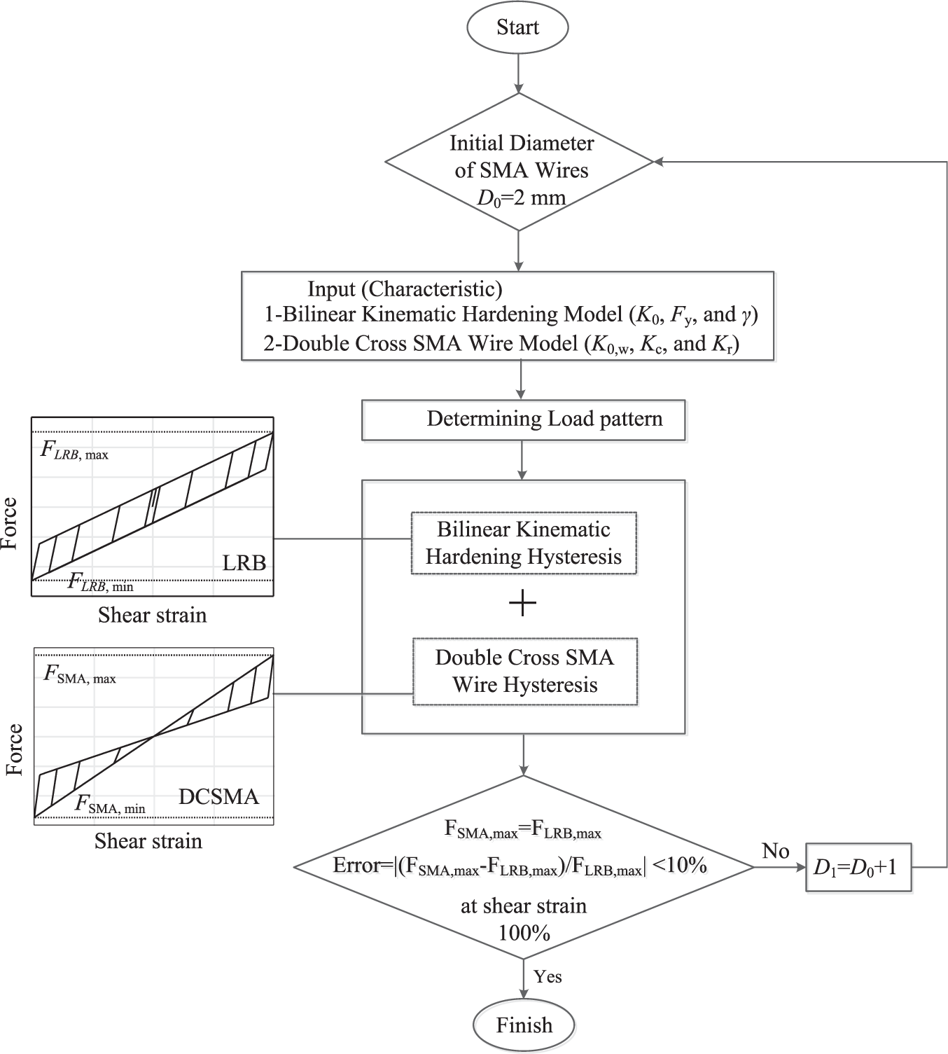
Design flow chart of determining the diameter of SMA wires.
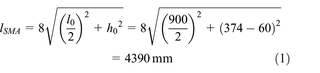
The geometry and dimension of the steel hooks with pulley (see Figure 1) are designed such that it can significantly reduce stress concentration in the SMA wires. The inner diameter, dinner, and height, hinner, of the steel hooks are assumed as 40 and 30 mm, respectively. The center-to-center distance, l0, of steel hooks (Figure 1(a)) is equal to 900 mm and the height between the pulleys, h0 is equal to 314 mm. The length of one single SMA wire, lSMA, can be calculated based on the configuration of the steel hooks as follows
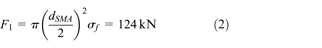
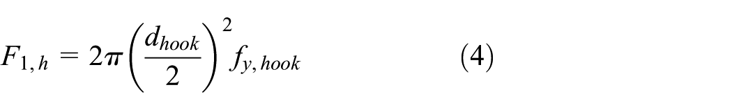
The maximum axial force, F1, of SMA wires with 14 mm diameter can be calculated as per equation (2) at limit shear deformation, that is, SMA wires reach to a maximum axial strain (15%). According to the special configuration of the wires, the corresponding shear deformation of SMA-LRB is 370 mm. The resultant force F1,h of SMA wires applied to the steel hook in the horizontal direction can be calculated as per equation (3). The yield strength of steel hook, fy,hook, is assumed as 345 MPa. Finally, the diameter, dhook, is determined as 13 mm according to equation (4). In actual design, the dimension of the pulley should be determined according to the SMA wires and steel hooks. Since the pulley can turn around the steel hook freely, the inner diameter of the pulley should be a little larger than that of the steel hook dimension (dhook). The dimension of the pulley’s groove should be larger than the diameter of the SMA wires

The LRB isolated bridge was designed as per seismic standards. Later SMA wires were installed in the LRB. Here, the intent of this study is to observe that the improvement in seismic response of the SMA-LRB isolated bridge compared to that of the LRB isolated one. In order to evaluate the performance of SMA wires in the SMA-LRB isolated bridge system, the SMA wires were designed according to the flow chart shown in Figure 7 and by considering the mechanical behavior of the LRB designed in the first case (LRB isolated bridge).
By considering the influence of connection mechanism between the tower/pier and the girder on seismic responses of a cable-stayed bridge, four different configurations are adopted in this study. (1) RS in which the deck is rigidly connected to the towers, but free at the pier locations (Figure 8(a)); (2) FS in which the deck can move freely at the towers and piers locations longitudinally (Figure 8(b)); (3) system isolated by LRB (LRBS) in which bearings are installed between the towers (piers) and the girder (Figure 8(c)); (4) system isolated by SMA-LRB (SMA-LRBS) in which SMA-based isolators are used rather than LRB (Figure 8(d)). Since the girder cannot move in the transverse direction at tower and pier locations according to the original design, the translational degrees of piers and girders are coupled in the vertical and transverse directions, and the girders are coupled with the towers in lateral degrees of freedom in the above four systems. In FS, the translational degrees of the piers and girders, and towers and girders are released in the longitudinal direction, whereas, in RS, the girders are coupled with the towers in longitudinal degrees of freedom. In LRBS and SMA-LRBS, the new elements implemented in OpenSees are used to connect the girders with the piers and towers, which act in the longitudinal direction. It should be noted that FS is a reasonable design case for an actual bridge. In the past, the main approach to control the seismically excited cable-stayed bridges was to support the bridge deck only by the cables, that is, the FS (Ali and Abdel-Ghaffar, 1995). Several as-built bridges are designed as FS, such as Yakohama Bay cable-stayed bridge (Japan) (Siringoringo et al., 2014), SCB (China) (Xing et al., 2013).
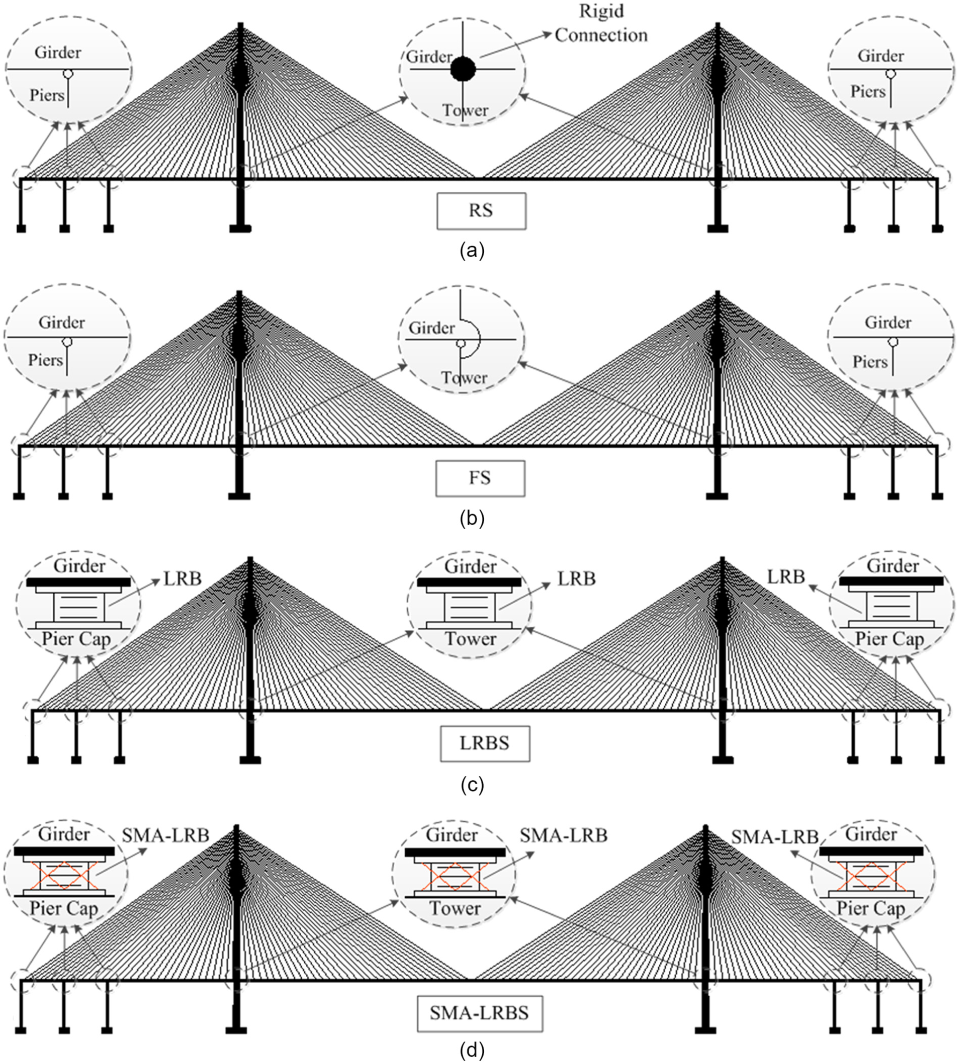
Configurations of different bridge systems: (a) floating system, (b) rigid system, (c) LRB system, and (d) SMA-LRB system.
FE model and dynamic characteristics
A three-dimensional FE model of SCB is generated in OpenSees to represent the full bridge system. The 3D model of the bridge without isolators is developed using 1883 joints and 2661 elements. This super-span bridge is a critical life-line facility which should remain functional without any damage after an earthquake in order to facilitate the rescue and relief operations. Therefore, the bridge is supposed to remain in elastic stage under earthquakes. The steel girders, transverse diaphragms, towers, and piers are modeled using elastic beam–column elements. The girder is discretized based on the suspended points of the stayed cables. 3D tension-only truss elements are used to model the cables, and the influence of sag on the stay-cables is neglected because it is much smaller than the oscillation under the seismic loads (Li et al., 2011). Girders are divided into a number of small discrete segments. The mass of each segment is assumed to be equally distributed between two adjacent nodes in the form of point mass. Newmark algorithm (Newmark, 1959) is used to integrate the nonlinear system of dynamic. The damping ratio is assumed to 2% according to the Guidelines for Seismic Design of Highway Bridges (JTG/T B02-01-2008, 2008).
The translational degrees of the towers (piers) and transverse diaphragms are coupled in the transverse direction, and the girder can move freely at the pier locations in the longitudinal direction for all four systems. In these FE models, both the towers and piers are considered to be fixed to their foundations. Following differences between four considered systems can be distinguished: (1) for RS, constrains are applied to restrict the girder and tower elements in both transverse and longitudinal directions (i.e. they are rigidly connected); (2) for FS, the girder is unrestricted with the towers and can move freely in the longitudinal direction; (3) for LRBS and SMA-LRBS, the isolation bearings are installed at the pier and tower locations.
Zero-length elements are used to model the bearings in which the SMA model and the LRB model are acting in parallel. The mechanical properties of LRB, which is idealized as a bilinear model, as well as the DC-SMAW model, are given in Table 2.
Mechanical properties of the LRB and DC-SMA wire.
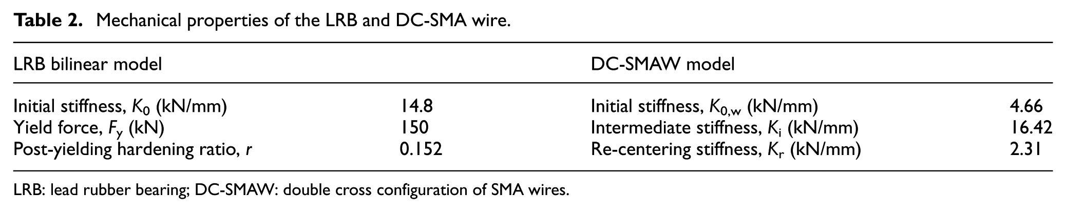
LRB: lead rubber bearing; DC-SMAW: double cross configuration of SMA wires.
Based on the FE models, the modal analysis of the bridge with and without isolators, using the block Lanczos method, is conducted in order to specify the natural periods of bridge structures. The austenitic or martensitic natural frequencies are not measured. However, austenitic SMA wires are used in the SMA-LRB isolated bridge. Table 3 lists the fundamental natural frequency and period of different systems. The natural period of the FS is about 3.7 times the ones for RS. The bridge with regular and smart isolators is in between FS and RS. The first five natural frequencies of FS are 0.061, 0.102, 0.187, 0.229, and 0.292 Hz (i.e. the corresponding periods are 16.3, 9.8, 5.3, 4.4, and 3.4 s) and the first mode is the longitudinal floating vibration. The dynamic characteristics are very close to those of previous results presented by other researchers (Xing et al., 2013). Compared to LRBS, SMA-LRBS (I and II) have lower periods because SMA wires increase the stiffness of isolation systems and as a result decrease their flexibility.
Natural frequencies and periods.
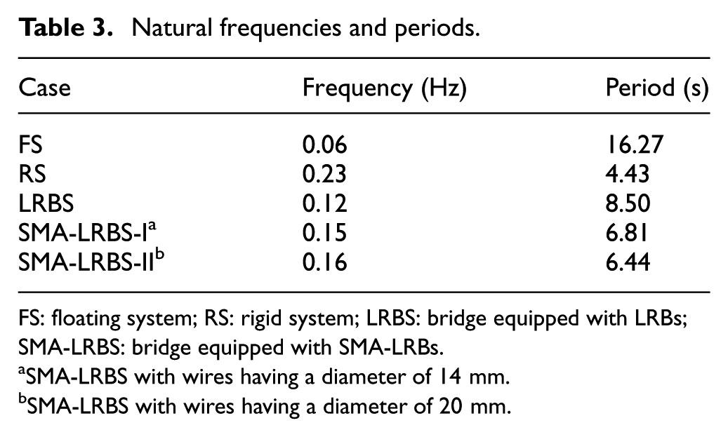
FS: floating system; RS: rigid system; LRBS: bridge equipped with LRBs; SMA-LRBS: bridge equipped with SMA-LRBs.
SMA-LRBS with wires having a diameter of 14 mm.
SMA-LRBS with wires having a diameter of 20 mm.
Near-fault ground motions
Based on Pacific Earthquake Engineering Research Center (PEER) strong motion database (PEER, n.d.), a total of 20 near-fault pulse-type and non-pulse ground motions from a variety of tectonic environments are chosen as the input. These records cover a range of frequency contents and pulse periods, with PGA values from 0.4g to 1.58g at a closest fault distance of 0.5 to 11.5 km. Table 4 lists the basic properties of the ground motions such as the closest distance to fault rupture, Rrup, peak ground acceleration (PGA), peak ground velocity (PGV), and pulse period, Tp. In order to avoid the interference to the nature of near-fault ground motions, original records without scaling are used in the dynamic time history analyses.
Description of the near-fault ground motions used in the analysis.
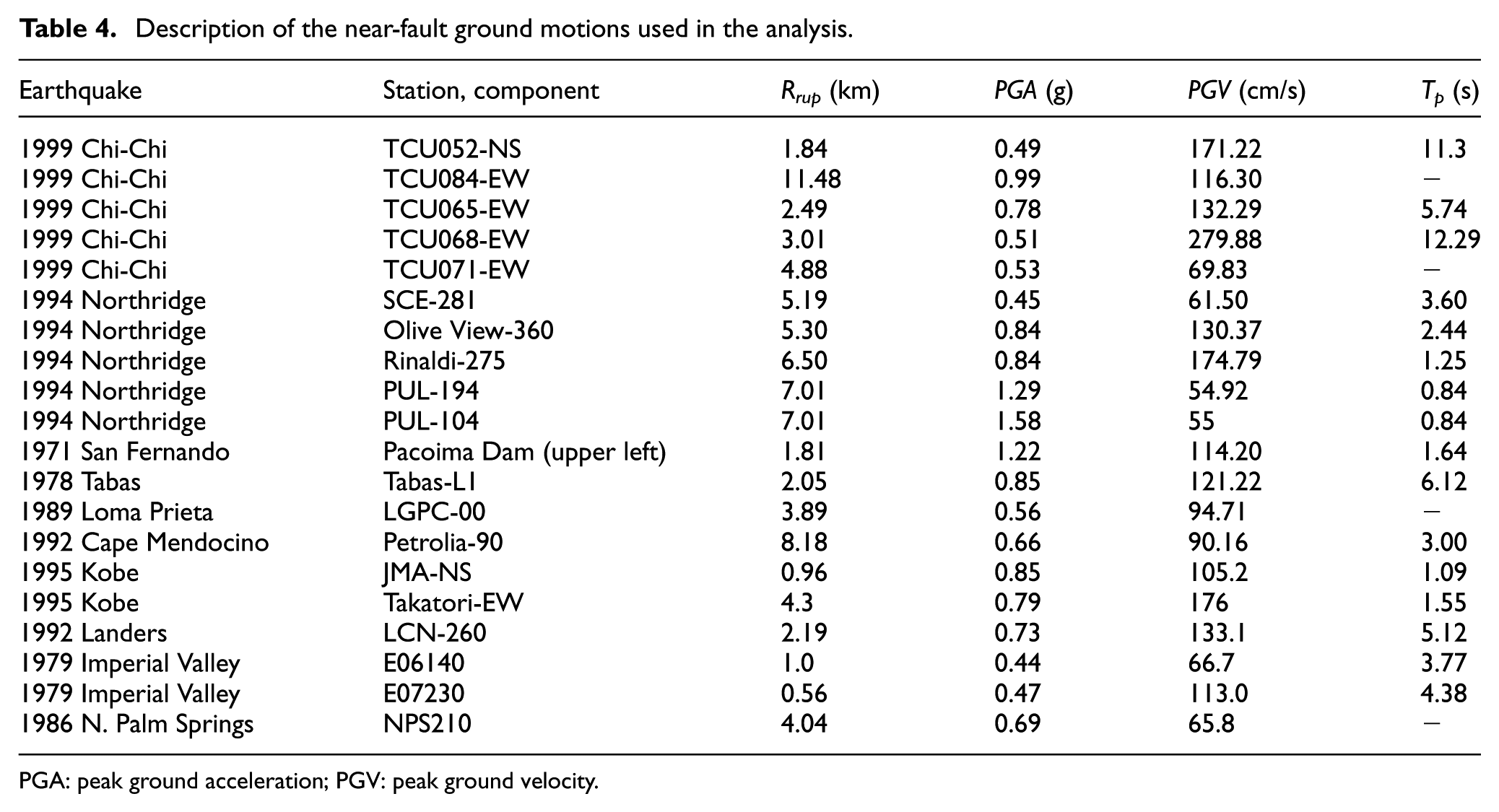
PGA: peak ground acceleration; PGV: peak ground velocity.
To explicitly investigate the effects of near-fault ground motions on the bridge, the selected ground motion records are applied in the longitudinal direction. The wave-passage effect and soil–structure interaction effect are ignored.
The 2% damped pseudo-acceleration spectra of 20 near-fault ground motions are plotted along with their mean amplitude in Figure 9. It shows that these records have large spectral values at long period.
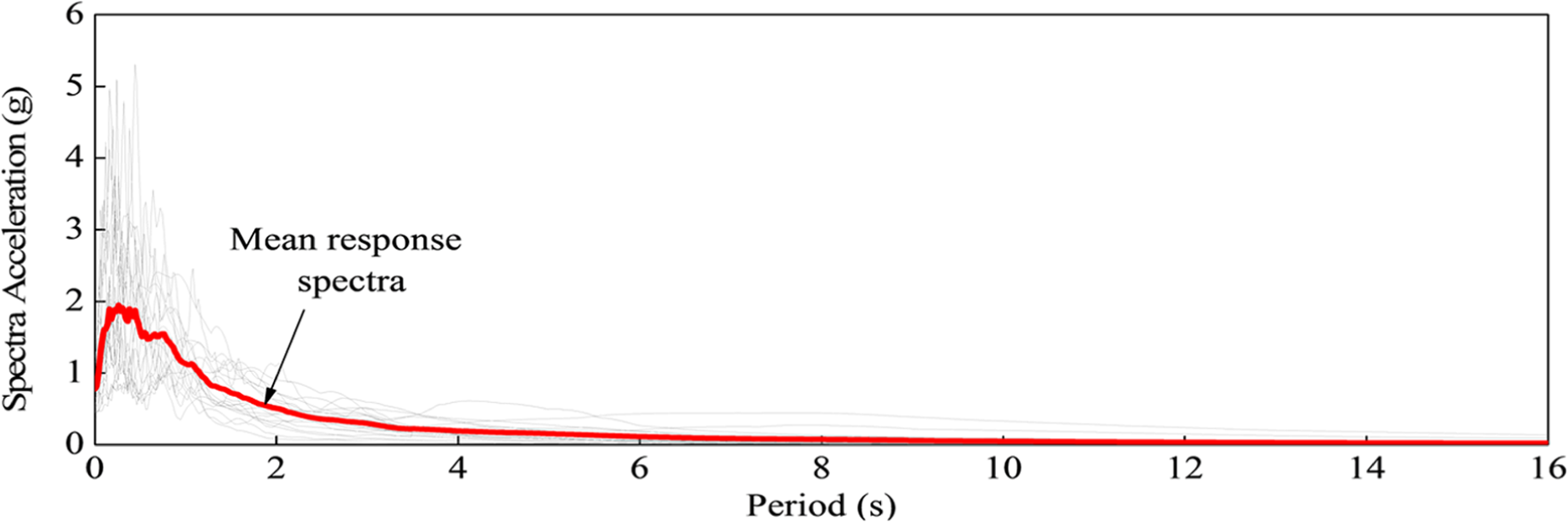
Spectra acceleration versus time period for 20 near-fault ground motions.
Governing equation of motion
The governing equations for a structural system under earthquake excitations can be derived by considering the equilibrium of all forces acting on it according to D’Alermbert’s principle. Different algorithms are used for isolated and non-isolated bridge system, for example, the restoring forces of LRB and SMA wires are considered in SMA-LRBs case. The general equations of motion of a bridge system can be written as
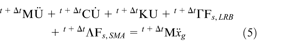
where M and C are the mass and damping matrices of the bridge system, respectively; t+ΔtK is the tangent stiffness matrix at time t + Δt; U,
Numerical results and discussion
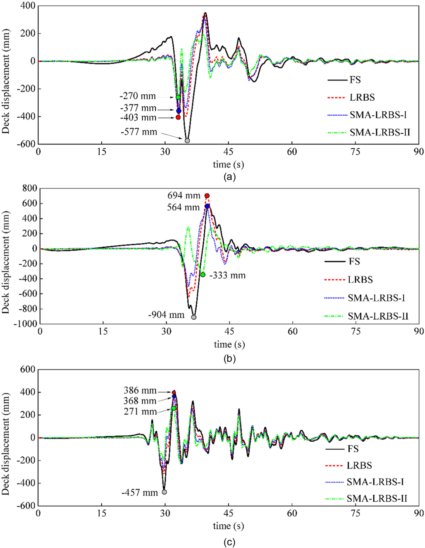
In order to evaluate the efficiency of LRBs and SMA-LRBs for the seismic response control of the SCB under near-fault ground motions, the seismic responses of the bridge equipped with these rubber bearings are compared with those of the reference bridge without isolators. The internal forces such as base shear and bending moment along the tower under earthquake excitations have been analyzed. Findings showed that the maximum forces of the tower occur at the base tower for this bridge. For simplicity, the displacement and acceleration of the deck and the base shear and bending moment of the left tower and the transition pier (pier 1) are obtained and compared with the reference bridge (RS and FS). To quantitatively compare the results, the peak responses subjected to 20 ground motions are obtained from dynamic time history analysis, and the average of 20 peak values is calculated and listed in a tabular format. The mean operational characteristics of LRBs and SMA-LRBs installed at different locations are also listed, including the effective horizontal stiffness, KH,eff, the equivalent viscous damping, β, the self-centering percentage, SCP, the dissipated energy, E, the maximum shear strain, γmax, and the residual deformation of the bearings, DResidual.
The effective horizontal stiffness of the bearings (KH,eff) is defined according to equation (6) under a specific shear strain amplitude (Naeim and Kelly, 1999)
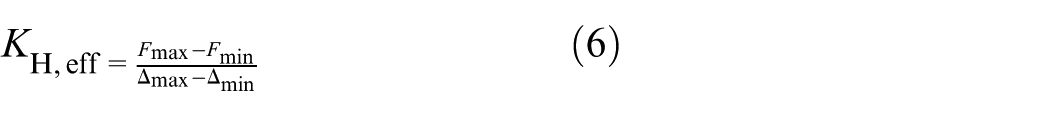
where Fmax and Fmax respectively denote the maximum and minimum shear forces in the horizontal direction under earthquakes; Δmax and Δmin are the maximum and minimum lateral displacements, respectively. The equivalent viscous damping β is defined as follows
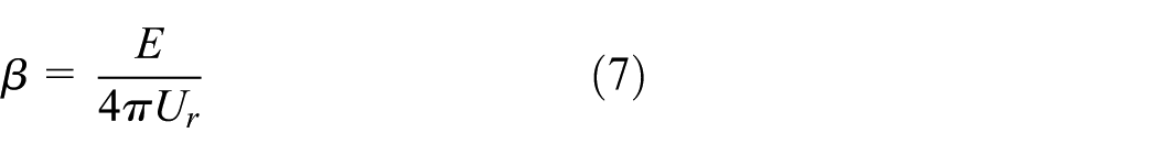
where E is the dissipated energy per cycle and equals to the area inside the hysteresis loops, which can be calculated as follows
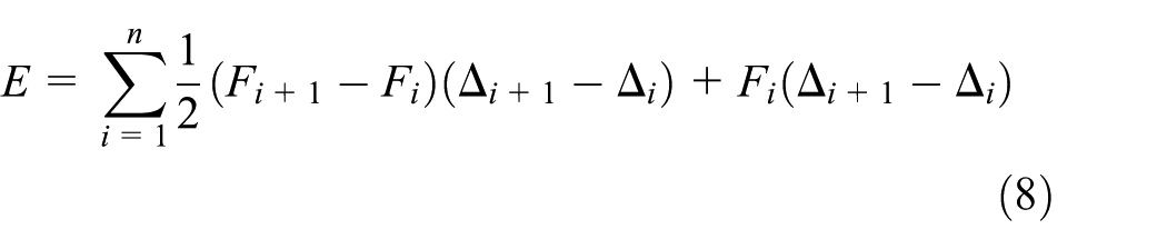
in which
Ur is the energy restored by the isolators, which can be calculated as follows (Toopchi-Nezhad et al., 2008)
in which
The SCP of the bearings is a representative of the re-centering capability of the isolator and defined as the ratio of the horizontal displacement at which the shear force in the isolator becomes zero during unloading phase in the last cycle (Δdis.zero), to the maximum displacement Δmax
The residual deformation of the bearings (DResidual) is the deformation that remains in the bearing at the end of the excitation. Since the objective of this study is to evaluate the effectiveness of the smart bearing in seismic control of a cable-stayed bridge, the influences of the pulse-type parameters such as pulse period, pulse type, and pulse amplitude are not considered.
Elastomeric bearings responses
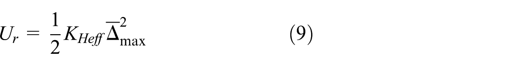
The bearing displacements are obtained from the relative displacements between the tower/pier and deck. For simplicity, the variation of shear strain (i.e. ratio of the lateral displacement to the total thickness of rubber layers in the isolator) and hysteresis curves of the bearings at pier 1 under three typical earthquake records are shown in Figures 10 and 11, respectively. The operational characteristics of the bearings under 20 near-fault records are obtained from dynamic history analysis, and then, the average value of each parameter is calculated and listed in Table 5. Due to the increase of horizontal stiffness, the peak shear strain of SMA-LRBs is much smaller than that of LRB (as listed in Table 5). The mean values for SMA-LRBs with 14 and 20 mm SMA wires at pier 1 are decreased by 20.9% and 48.3%, respectively, compared to those of LRB. Similar trends can be observed for the bearings at piers 2 and 3. Note that the peak shear strain of LRB under TCU068-EW is higher than 150% (see Figure 10(a)). Instability in elastomeric bearings results from a reduction in the horizontal stiffness under increasing axial load and increasing lateral displacement (Sanchez et al., 2012). Since the lateral displacement of LRB is much higher than that of SMA-LRB, it means that the possibility of LRB’s instability is higher than that of SMA-LRB. The instability of elastomeric bearings can be conservatively evaluated using the reduced-area formulation (Buckle and Liu, 1994). Since SMA wires can noticeably reduce the shear strain demand (see Figure 10(a)), the over-displacement is prevented and as a result, the instability will not occur. However, the mean peak displacements of the bearings at tower locations in cases of LRB and SMA-LRBs are very close to each other. This phenomenon may be attributed to the fact that the ratio of the LRB’s horizontal stiffness to the tower’s stiffness is almost same as the ratio of the SMA-LRBs’ horizontal stiffness to the tower’s stiffness. It is because the stiffness of the tower with a super dimension is much higher than the stiffnesses of either LRB or SMA-LRBs. Therefore, the increase of the SMA’s diameter can decrease the relative deformation of the bearings at piers having a relatively small stiffness, but has a negligible influence on the relative deformation of the bearings located at towers.
Time variation of lateral displacement of LRBS, SMA-LRBS-I, and SMA-LRBS-II at pier 1 under (a) TCU068-EW, Chi-Chi; (b) TCU065-EW, Chi-Chi; and (c) Pacoima Dam (upper left), San Fernando.
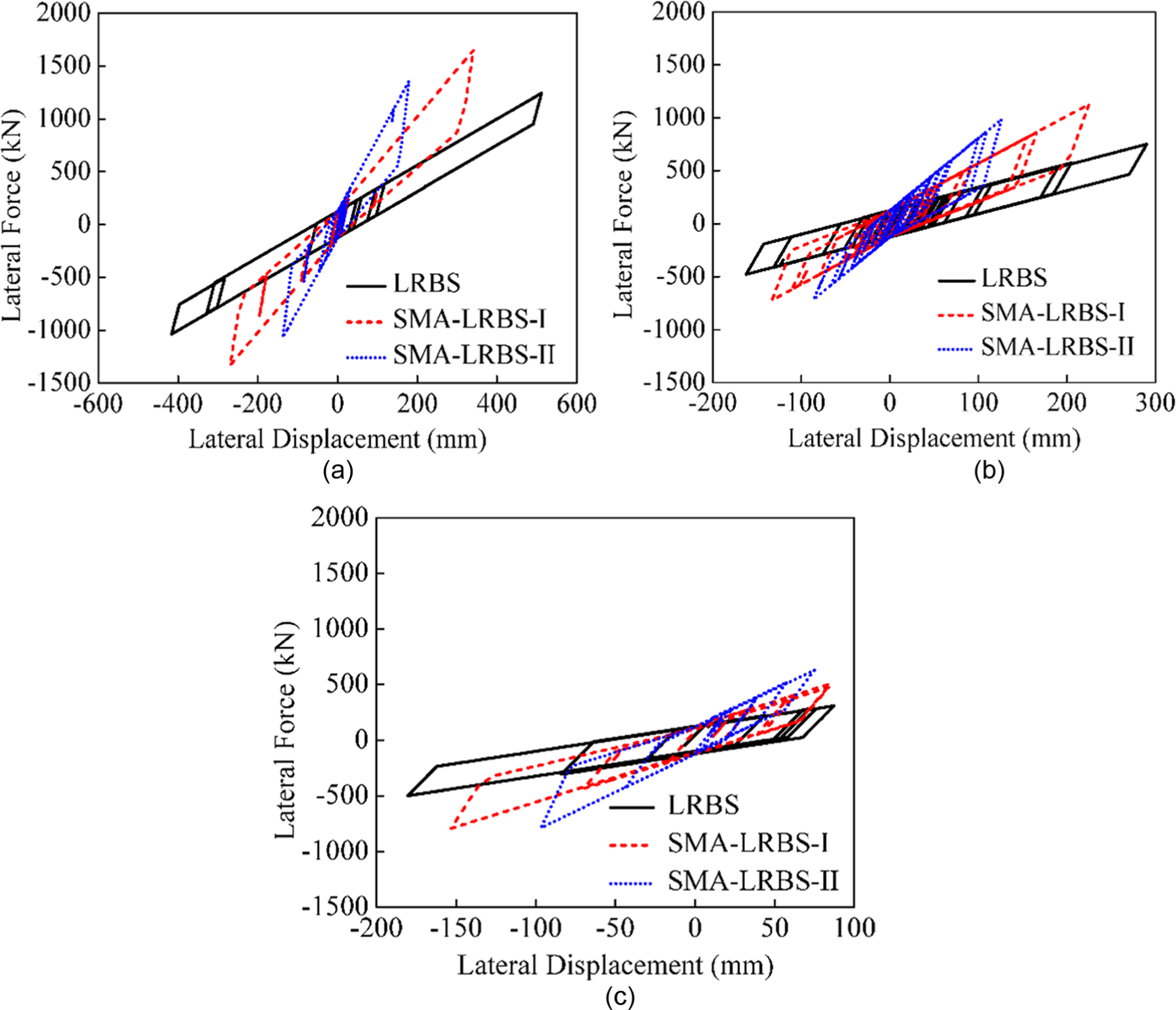
Shear force–displacement curves of LRBS, SMA-LRBS-I, and SMA-LRBS-II installed at pier 1, under (a) TCU068-EW, Chi-Chi; (b) TCU065-EW, Chi-Chi; and (c) Pacoima Dam (upper left), San Fernando.
Mean operational characteristics of LRB and SMA-LRBs installed at different locations.
LRB: lead rubber bearing; SMA-LRB: shape memory alloy wire-based lead rubber bearing; SCP: self-centering percentage.
It can be seen from Figure 11 that the horizontal stiffness of SMA-LRBs is much higher than that of LRB. The average values of the stiffness of SMA-LRB-I (DSMA = 14 mm) and SMA-LRB-II (DSMA = 20 mm) at pier 1 are respectively 77.9% and 171.9% higher than that of LRB. Therefore, it is understood that SMA-LRBs transfer a higher amount of shear force to the superstructure due to a higher stiffness. Another point is that reducing the residual deformation of the LRB by implementing SMA wires shows the superior self-centering capability of SMA-LRBs (see Figure 11). It should be mentioned that the residual deformation is obtained from the stable absolute values of the time history of the bearings’ lateral deformation at the last 5 s (see Figure 10). Compared to the LRB, SMA wires with 14 and 20 mm diameters can reduce the residual displacement of the LRB by 47.8% and 56.1%, respectively. The reduction in the SCP of SMA-LRBs (I and II) at pier 1 are 36.7% and 43.6%, respectively. It was also found that SMA wires have excellent capability in controlling the residual deformation of the LRB at tower location (more than 94% reduction). It can be concluded that larger SMA wires are more effective in enhancing the re-centering property of elastomeric isolators.
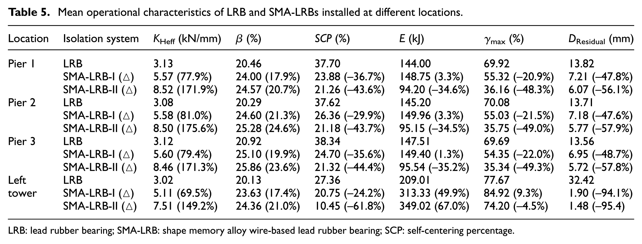
Another important characteristic of bearings is the energy dissipation capacity. The energy dissipated (E) by LRB, SMA-LRB-I and SMA-LRB-II are evaluated and presented in Table 5. It is expected to observe an enhancement in the energy dissipation capacity of SMA-LRBs compared to LRB because of the SMA wires. However, since these supplementary elements (wires) decrease the shear displacement of the bearings at piers, SMA-LRBs may have lower or higher energy dissipation capacity than LRBs depending on the level of displacement reduction. When SMA-LRBs located at piers are compared, it is observed that SMA-LRB-II (with larger wires and as a result, lower shear strain demand) has a lower energy dissipation capacity. According to the results listed in Table 5, the dissipated energies of LRB and SMA-LRBs with 14 and 20 mm diameters installed at pier 1 is 144, 148.75, and 94.20 kJ, respectively. It should be noted that if the maximum lateral displacement is the same for SMA-LRB and LRB, the dissipated energy of the smart isolator is significantly higher than that of the regular bearing (LRB). SMA-LRB-I and SMA-LRB-II installed at towers can noticeably increase the dissipated energy up to 49.9% and 67.0%, respectively, compared to LRB. This fact reveals that SMA-LRB has a superior damping property (see Figure 12). From the dissipated energy as estimated for LRBs and SMA-LRBs, the damping ratio of each bearing can also be determined, as shown in Table 5. As expected, SMA wires can increase the equivalent viscous damping, for example, the damping increases by 17.9% and 20.7%, respectively, for SMA-LRB-I and SMA-LRB-II at pier 1 compared to LRBs.
Shear force–displacement curves of LRBS, SMA-LRBS-I, and SMA-LRBS-II installed at the left tower, under (a) TCU068-EW, Chi-Chi; (b) TCU065-EW, Chi-Chi; and (c) Pacoima Dam (upper left), San Fernando.
Deck responses
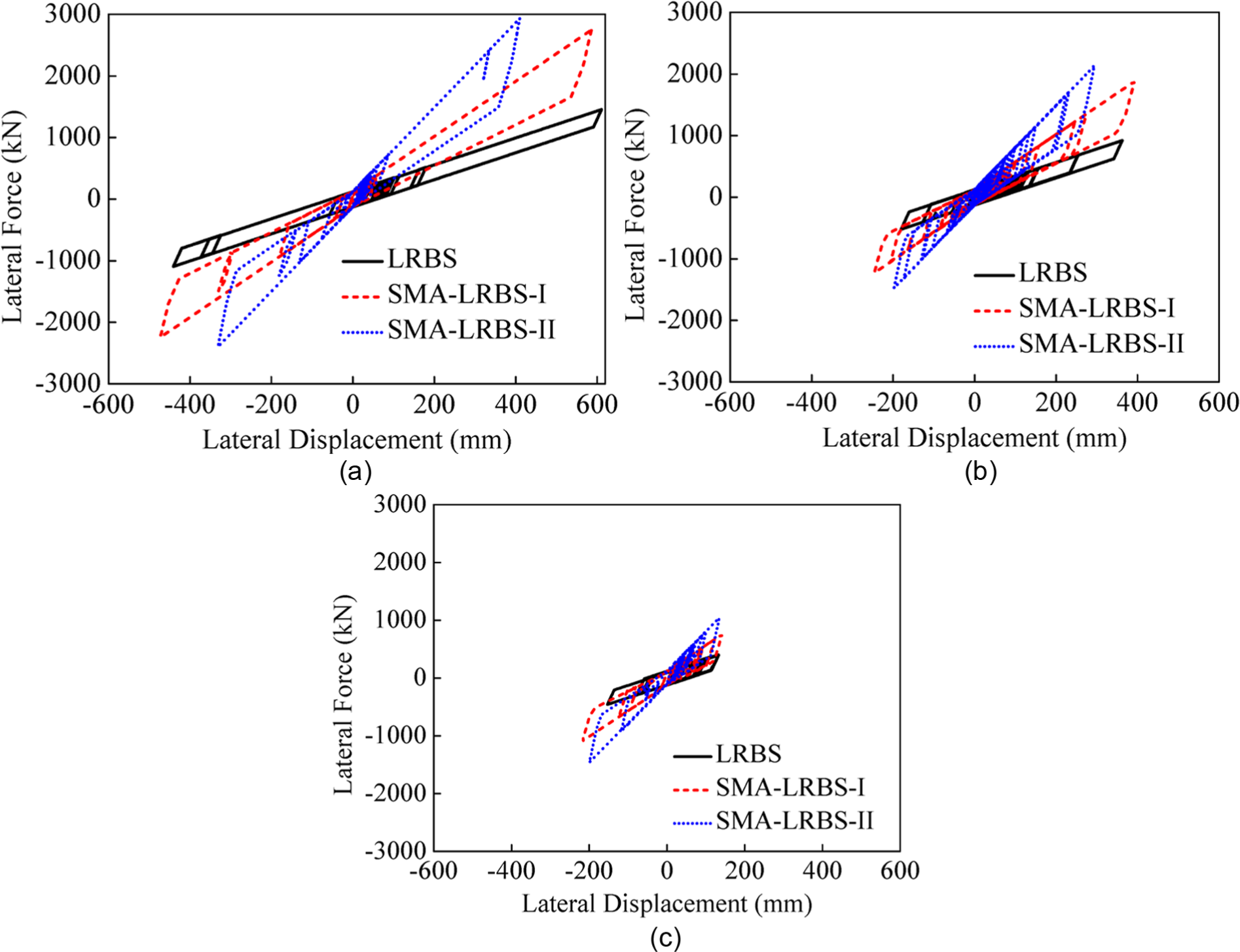
The connection configuration of the tower to the deck is critical to the seismic response of a cable-stayed bridge. For FS, the induced seismic forces in the towers will have a minimum value, whereas the deck displacement will be kept at a maximum value. On contrast, in the case of RS, a minimum deck displacement will be obtained, which causes a significant increase in the bending moment and shear force demands of towers. Therefore, it is of great interest to reduce the longitudinal deck displacement for FS and the induced seismic forces in the towers for RS. In this regard, the time history curves of the longitudinal deck displacements of the mid-span point for FS, and the systems fitted with LRB and SMA-LRBs (LRBS, SMA-LRBS) subjected to three most destructive earthquake records are plotted in Figure 13.
Time history of the longitudinal deck displacement: (a) TCU052-NS, Chi-Chi, (b) TCU068-EW, Chi-Chi, and (c) TCU065-EW, Chi-Chi.
Since the elastomeric rubber bearings isolate the bridge deck from piers, the deck acceleration has a direct effect on the internal forces of the piers. In this regard, it is critical to study the effect of bearings on the deck acceleration. The RS is taken as the reference bridge. The time history curves of the deck accelerations measured in mid-span point for RS, LRBS, and SMA-LRBS subjected to three most destructive earthquake records are presented in Figure 14.
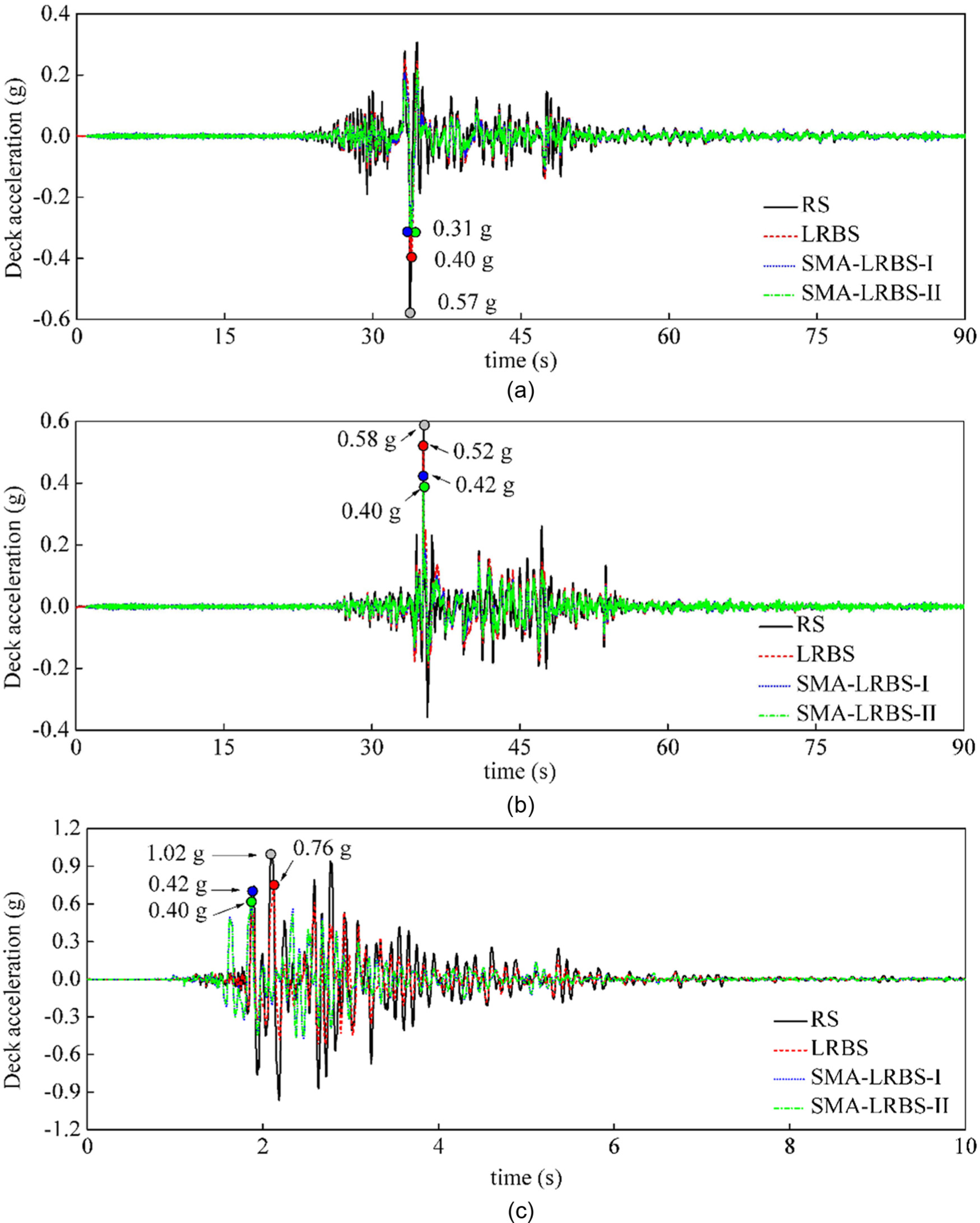
Time history of the deck acceleration: (a) TCU052-NS, Chi-Chi, (b) TCU068-EW, Chi-Chi, and (c) JMA-NS, Kobe.
It can be observed from Figure 13 that the bridge without seismic isolation (FS) experiences a larger deck displacement compared to LRBS, SMA-LRBS-I, and SMA-LRBS-II. Due to the increase of horizontal stiffness, both LRB and SMA-LRB can effectively restrict the deck displacement. Among the isolated systems, the SMA-LRBS-II has the smallest deck displacement, while LRBS has the maximum value. Compared to the reference case (FS), the maximum values of deck displacement for LRBS, SMA-LRBS-I, and SMA-LRBS-II decrease by 11.76%, 16.20%, and 28.27%, respectively. Similar trend is also observed for the deck acceleration in Figure 14. The bridges fitted with LRB and SMA-LRBs I and II experience smaller deck accelerations compared to RS. This fact reveals that the isolators used in the bridge can reduce the induced forces of the piers, which will be also validated in the next section. SMA-LRBs cause smaller deck accelerations than LRB, and the deck acceleration in the case of SMA-LRB-II is a little smaller than that in the case of SMA-LRB-I. In fact, in addition to the stiffness, the energy dissipation capacity of the isolation system has a direct effect on the deck acceleration and, as a result, on the base shear. According to energy-based design method, the seismic energy formulations of isolated bridge structures can be expressed as

where EK, Eξ, EA, and EI denote the kinetic energy, damping energy, elastic strain energy, and input energy, respectively. Having an isolation system with a higher energy dissipation capacity (i.e. SMA-LRB) increases the damping energy Eξ, and considering the fact that EI (input energy) is constant, the kinetic energy and the elastic strain energy (EK + EA) should decrease. The kinetic energy is a function of mass and velocity, and the elastic strain energy is a function of stiffness, and displacement. Since the stiffness of the bridge column is constant, and the stiffness of isolation system increases as a result of using SMA wire, the displacement has to reduce in order to have lower elastic strain energy in total. The relationship between the displacement and the base shear is in equation (13)
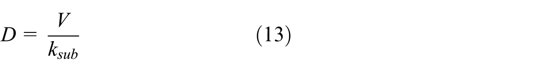
where D is the displacement of the top of the column; V is the base shear at the support; and ksub is the stiffness of the substructure (column), which is a constant value.
As can be seen in equation (13), the displacement has a proportional relationship with the shear force. Therefore, when the displacement decreases, the base shear of bridge columns equipped with SMA-LRB will decrease. Considering the bridge pier as a single-degree-of-freedom system, a lower displacement in the column equipped with SMA-LRB (case I) compared to the column equipped with the LRB (case II) shows that a lower amount of shear force is transmitted from the superstructure to the substructure in case I. Hence, the deck acceleration should be smaller for the bridge isolated by SMA-LRB. Similarly, Jangid (2004) discussed that the isolation system with a high-energy dissipation capacity can reduce both the deck acceleration and base shear of the piers.
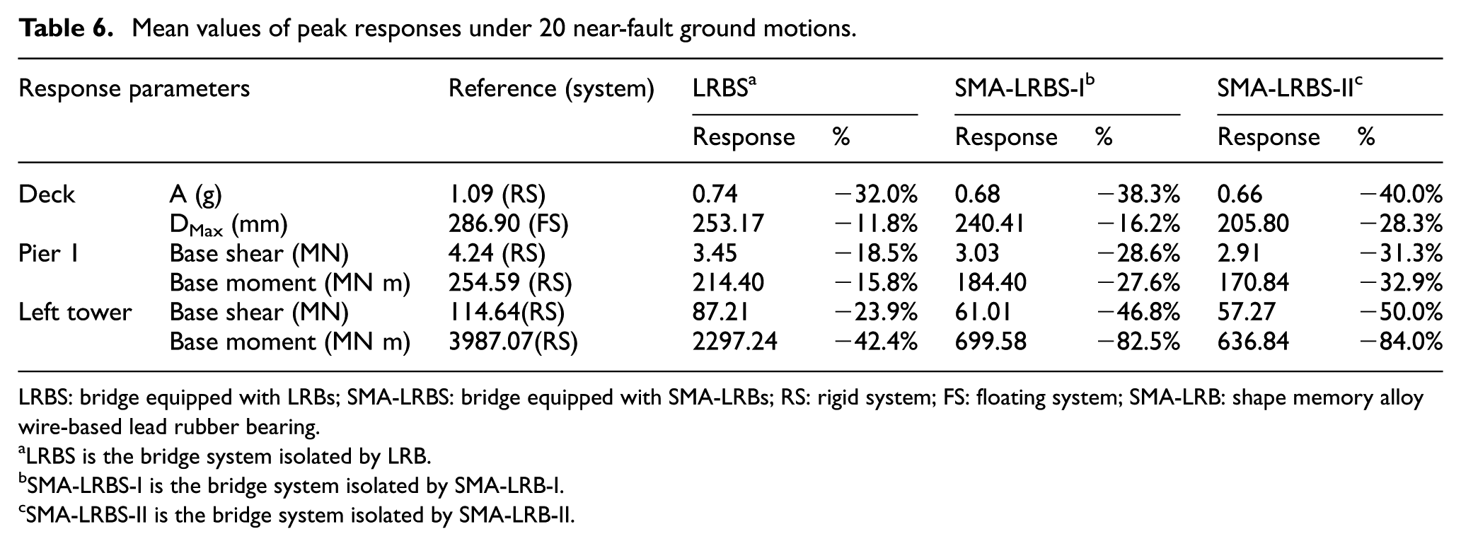
As listed in Table 6, LRB, SMA-LRB-I, and SMA-LRB-II could reduce the peak deck acceleration of RS by 31.98%, 36.96%, and 38.62%, respectively. However, under some seismic excitations, the deck acceleration in the case of SMA-LRB-II may be higher than or equal to that in the case of SMA-LRB-I (e.g. the case shown in Figure 14(a)). This phenomenon can be attributed to the difference of records’ frequency content. Note that the frequency content of the input ground motions has direct influence on the responses of structures.
Mean values of peak responses under 20 near-fault ground motions.
LRBS: bridge equipped with LRBs; SMA-LRBS: bridge equipped with SMA-LRBs; RS: rigid system; FS: floating system; SMA-LRB: shape memory alloy wire-based lead rubber bearing.
LRBS is the bridge system isolated by LRB.
SMA-LRBS-I is the bridge system isolated by SMA-LRB-I.
SMA-LRBS-II is the bridge system isolated by SMA-LRB-II.
Tower responses
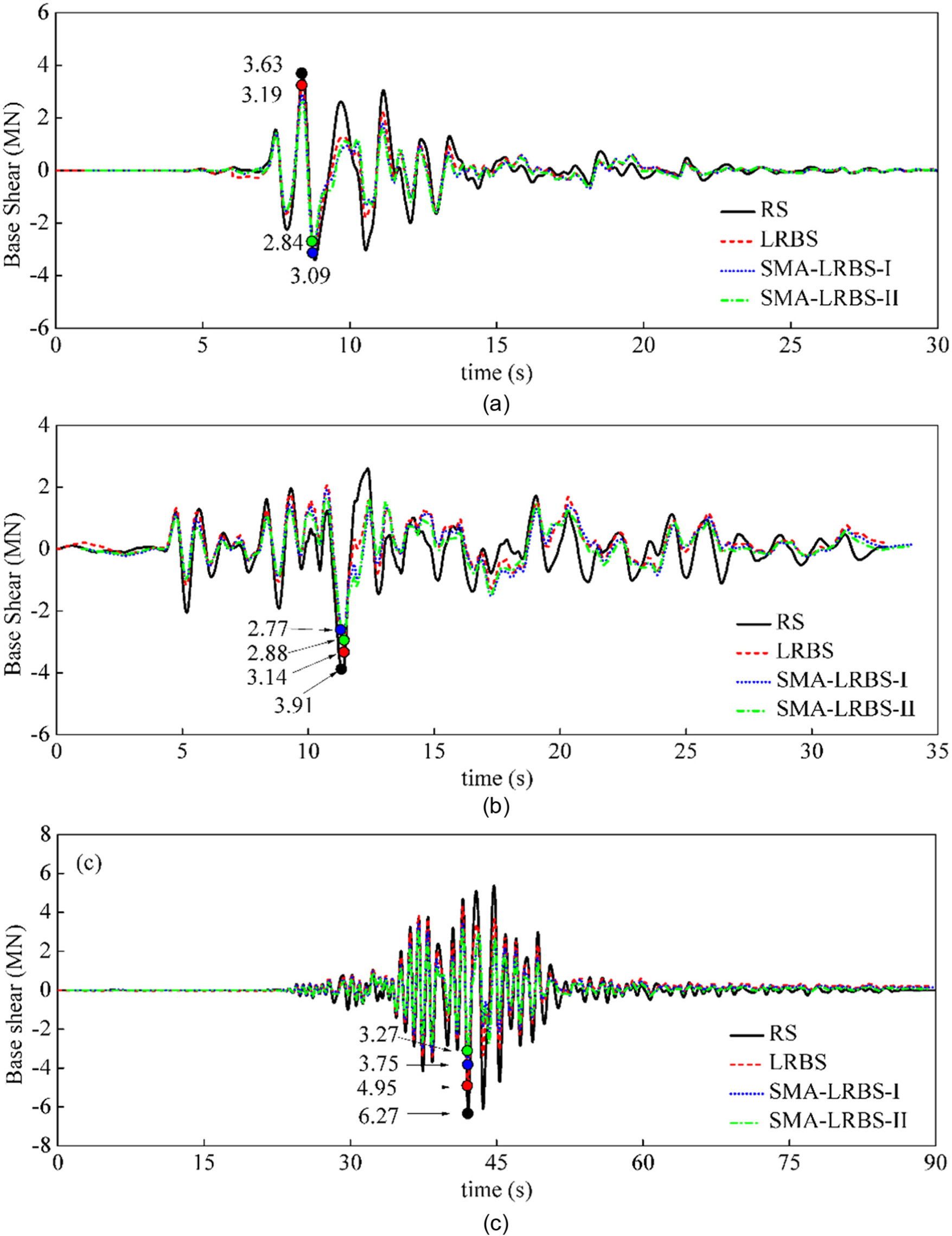
In a cable-stayed bridge system, the tower, which supports the cable system and transfers forces to the foundation, is a key component. Considering a huge repair cost, tower should remain elastic without damage after an earthquake. In this section, the internal forces of the towers are obtained to validate the efficiency of the isolators used in cable-stayed bridge. Results of time history of the base shear and bending moment at the tower base under three most destructive seismic events are presented in Figures 15 and 16. The bridge with rigid connection (RS) is taken as reference. The results obtained with and without isolators are plotted in the same figures for comparison. It can be observed from Figure 15 that all isolators can significantly reduce the base shear. Due to the energy dissipation of the bearings, the induced seismic forces transferred to towers are reduced and as a result, the internal forces of the towers decrease. SMA-LRBs show a better performance in terms of base shear reduction compared to LRB. The mean values of the peak base shear are reduced by 23.93%, 46.78%, and 50.04%, when LRB, SMA-LRB-I, and SMA-LRB-II are used at towers, respectively. A similar trend can be observed in Figure 16 where LRBs and SMA-LRBs could noticeably decrease the bending moment. In Table 6, the mean values of the peak bending moment for LRBS, SMA-LRBS-I, and SMA-LRBS-II encounter 42.38%, 82.45%, and 84.03% decrease, respectively, compared to the RS. This fact indicates that SMA-LRB-I and SMA-LRB-II can decrease the internal force more efficiently compared to LRBs. The smaller deck acceleration, the smaller inertia force will be transmitted from the deck to the tower or pier. Hence, the deck acceleration will have a trend similar to the base shear.
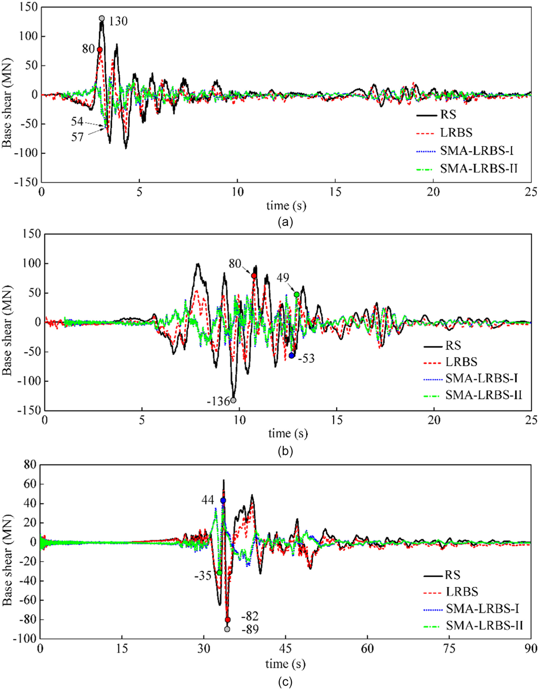
Time history of the base shear in the towers subjected to (a) Petrolia-90, Cape Mendocino; (b) LGPC-00, Loma Prieta; and (c) TCU052-NS, Chi-Chi.
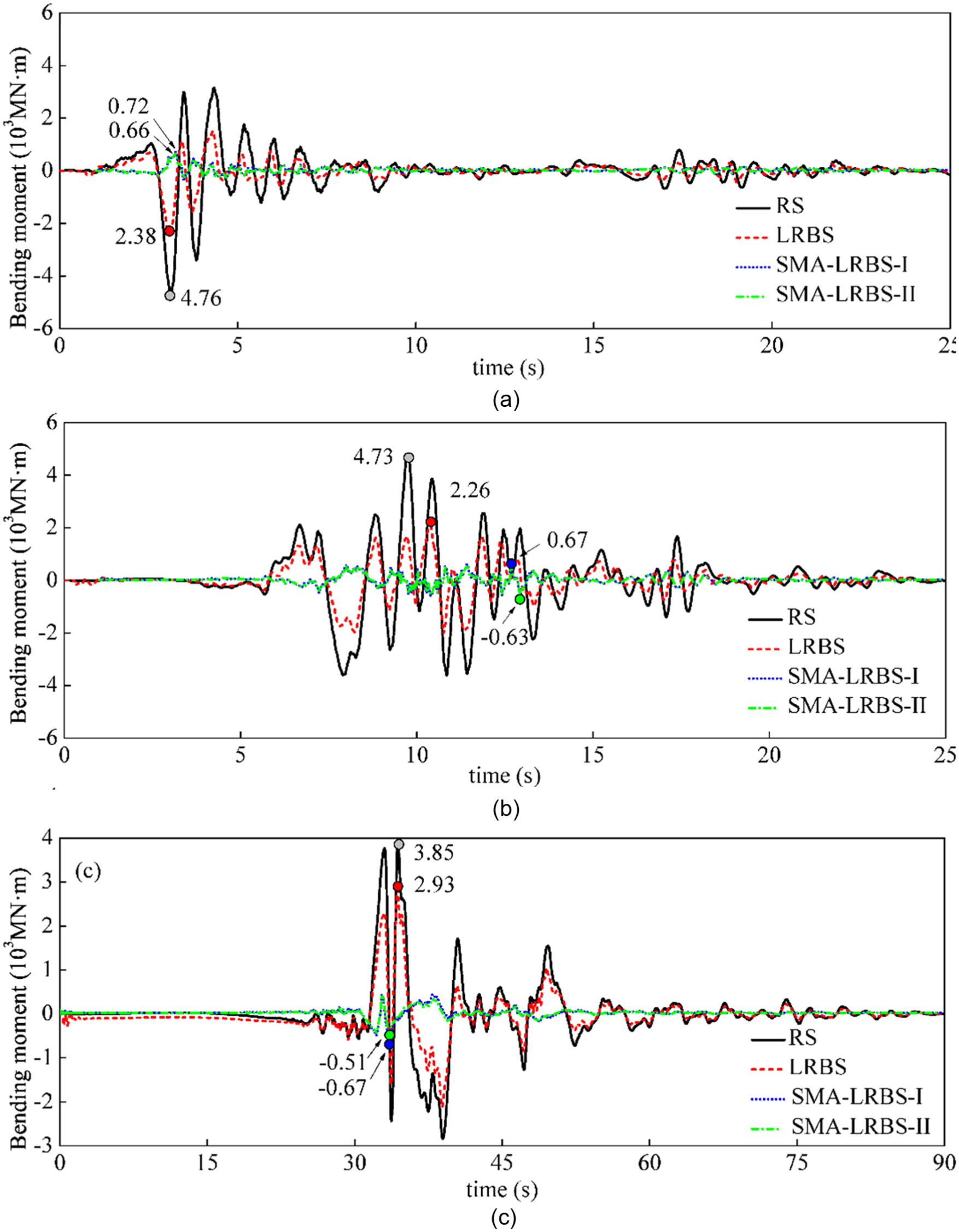
Time history of the bending moment in the towers subjected to (a) Petrolia-90, Cape Mendocino; (b) LGPC-00, Loma Prieta; and (c) TCU052-NS, Chi-Chi.
It should be mentioned that the influence of wires’ dimension on the bending moment and the base shear responses is not significant because the deck acceleration in SMA-LRBS-I and SMA-LRBS-II are very close to each other.
The maximum base shear and bending moment of the towers for RS under 20 near-fault records are 136 MN (see Figure 16(b)) and 4.7×10³ MN m (see Figure 16(a)), respectively. A 3D FE model of SCB considering the nonlinear behavior of the towers was generated by Zhang (2016). The yielding forces of the base shear and bending moment are about 180 MN and 5.1×10³ MN m, respectively. Additionally, when LRB, SMA-LRB-I, and SMA-LRB-II are used at towers, the internal forces of the towers are noticeably reduced. Hence, the assumption that the towers remain elastic under earthquake excitations can be verified, and the numerical model used in this study is appropriate.
Pier responses
Time histories of the base shear and bending moment at the pier base under three most destructive earthquake records are illustrated in Figures 17 and 18. It is observed that the isolators can decrease the internal forces of the piers effectively compared to the non-isolated bridge (RS). When LRB or SMA-LRBs are used to isolate the deck from the pier, the displacement of the deck is not completely transferred to the pier and accordingly, the internal force of the piers is reduced. Peak base shears of the piers in cases of SMA-LRBS-I and SMA-LRBS-II are very close to each other. In fact, increasing the dimension of SMA wires, which increases the horizontal stiffness of the isolation system, is not beneficial for the force condition of piers, and in some cases, it may amplify the internal forces. For example, the internal forces of the piers equipped with SMA-LRB-II are a little higher than those of the piers equipped with SMA-LRB-I under Tabas record, as shown in Figures 17(b) and 18(b). As listed in Table 6, LRB and SMA-LRBs I and II could reduce the peak base shear of the piers by 18.51%, 28.58%, and 31.28%, respectively, compared to the non-isolated bridge. Meanwhile, the mean values of maximum bending moment for LRBS, SMA-LRBS-I, and SMA-LRBS-II decrease by 15.79%, 27.57%, and 32.90%, respectively.
Time history of the base shear of the piers: (a) JMA-NS, Kobe; (b) Tabas-L1, Tabas; and (c) TCU084-EW, Chi-Chi.
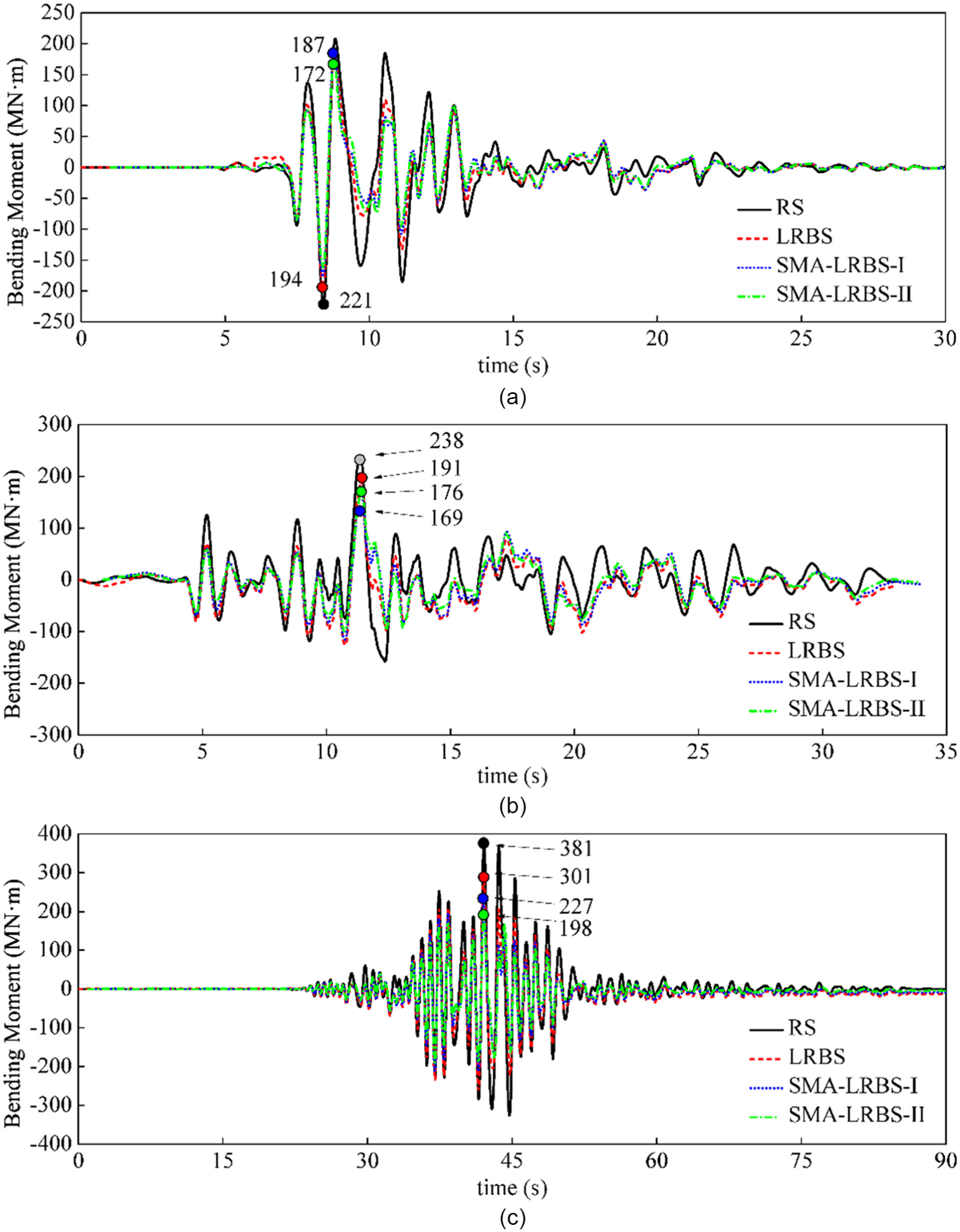
Time history of the bending moment of the piers: (a) JMA-NS, Kobe; (b) Tabas-L1, Tabas; and (c) TCU084-EW, Chi-Chi.
Conclusion
The objective of this study was to assess the efficiency of a new generation smart elastomeric isolator (i.e. SMA-LRB) with superior re-centering property and energy dissipation capacity in controlling the seismic response of a long-span cable-stayed bridge system under severe earthquakes. For this purpose, a newly developed constitutive model of SMA wire-based rubber bearings was implemented in OpenSees and numerical FE simulations were conducted based on this model. SCB, with a main span of 1088 m, was modeled. Considering the importance of the connection configuration between the tower and deck, four different FE models of the bridge were developed, including RS, FS, LRBS, and SMA-LRBS. The structural responses were obtained from dynamic time history analyses for a set of 20 near-fault ground motions containing non-pulse records and impulsive records. The seismic performance of the bridge equipped with different isolators was evaluated and conclusions are summarized as follows:
Comparing the results of OpenSees with the real shear hysteretic response of SMA-LRBs under different excitations shows that this FE-based structural software (OpenSees) is capable of correctly capturing the nonlinear behavior of SMA-LRBs.
Using double cross SMA wires made of iron-based alloys (FeNiCoAlTaB) with around 13.5% superelastic strain limit could reduce the shear strain demand in SMA-LRBs by increasing the effective stiffness of elastomeric isolator. This characteristic of SMA wires can prevent the bearings from over-displacement and, as a result, improve their stability. Using SMA wires could effectively enhance the self-centering capability and reduce the residual deformation under near-fault ground motions. By increasing the dimension of the SMA wire, the peak shear strain of SMA-LRBs at pier locations was decreased, but it has a negligible influence on the relative deformation of the bearings located at towers. Another finding was that the flag-shaped hysteresis of SMA with zero residual deformation could increase the energy dissipation capacity of LRB.
In terms of the deck displacement, the constraints could effectively control the deck response. In this regard, SMA-LRB with larger wires is a better option. A superior performance was achieved in terms of the deck acceleration for the bridges fitted with SMA-LRBs. It is due to the fact that both stiffness and energy dissipation capacity of isolation system directly affect the deck acceleration.
SMA-LRBs considerably reduced the internal forces of the towers and could safely protect towers from damage under near-fault ground motions by decreasing the acceleration of the bridge deck. As an example, SMA-LRB-I (DSMA = 14 mm) was able to reduce the towers base shear and base moment by 47% and 83%, respectively, compared to the reference bridge with rigid connection (RS).
SMA-LRBs could improve the seismic performance of the piers in terms of the base shear and base moment. As an example, SMA-LRB-I (DSMA = 14 mm) could reduce the mean of peak base shear and base moment of the piers by 28.6% and 27.6%, respectively, compared to the non-isolated bridge. It should be mentioned that a larger diameter of SMA wires may be unbeneficial for the performance of piers due to the increase of the horizontal stiffness.
Here, SMA wires were installed on the designed LRB for bridge isolation. Future research works are needed to determine the design procedure for bridges isolated with SMA-LRB. Thus, the performance comparison of the LRB and SMA-LRB isolation systems should be based on two distinct design methods for the two isolated bridges. Here, an idealized rate-independent constitutive model is used to represent the SMA where the proposed hysteresis model developed by the authors is independent of the strain rate effect. The influence of strain rate and thermo-mechanical effects on the hysteresis of SMA wire-based rubber bearing will be studied in future works. Besides, the transverse seismic responses of the bridge and material nonlinearity of the towers are not considered in the current study. In a future study, the seismic vulnerability of cable-stayed bridge system (considering the material nonlinearity) equipped with SMA-LRBs will be evaluated under bi-directional excitations.
Footnotes
Declaration of conflicting interests
The author(s) declared no potential conflicts of interest with respect to the research, authorship, and/or publication of this article.
Funding
The author(s) disclosed receipt of the following financial support for the research, authorship, and/or publication of this article: This study was supported by Natural Sciences and Engineering Research Council (NSERC) of Canada through Discovery Grant, UBC Faculty of Applied Science, and National Natural Science Foundation of China (grant no. 51378110), Scientific Research Foundation of Graduate School of Southeast University (grant no.YBJJ1611), Graduate Student Research Innovation Project of Jiangsu Province (grant no. KYLX15_0086), and Priority Academic Program Development of Jiangsu Higher Education Institutions (grant no. CE02-2-6). The financial supports are greatly appreciated.