
Abstract
Constraining a piezoelectric material from freely expanding causes a reduction in capacitance. This reduction in capacitance has implications in energy harvesting, active vibration control, and ultrasonic sensing. This article investigates the reduction in capacitance when a thin piezoelectric disk is embedded in an isotropic host material. Both simplified (one-dimensional axisymmetric) and computational (finite element two-dimensional axisymmetric) analyses have been presented and used to calculate the expected reduction in capacitance of thin embedded piezoelectric disks for a number of ceramic-based piezoelectric materials. The analyses show that there is a non-linear relationship between the capacitance and the elastic modulus of the host material; with increasing host modulus, capacitance initially decreases rapidly but then asymptotically converges to the fully constrained case. A simplified equivalent spring axisymmetric model has been derived from the finite element model and has been used to explain some of the key geometric and material properties that effect the reduction in embedded capacitance. Preliminary experimental results show some agreement with the derived models; however, substantial further validation is required. Some implications of the derived results for energy harvesting are also discussed.
Introduction
Most research in piezoelectric-based smart materials has focused on energy harvesting, vibration control, or structural health monitoring. The majority of research has used surface-mounted transducers in which the piezoelectric material is bonded to the surface of the host structure. Surface mounting is generally an easy and reliable procedure that can be used for both new and existing structures. Due to the increased complexity and the possibility of damaging either the sensor or associated electrical wiring during manufacturing, comparatively less research work has been done on embedded piezoelectrics (i.e. the transducer is placed below the surface of the host structure). There have also been some concerns that the embedding weakens the host structure and that embedded transducers are difficult to replace or repair when damaged. Currently, piezoelectric transducers have only been embedded into cast structures (such as concrete and resin-based composites). However, with the rapid improvements in additive manufacturing, it is feasible that piezoelectric transducers can also be included into other host materials (even metals). Embedded piezoelectric transducers in composites have been studied by a number of researchers including Lin and Chang (2002), Paget and Levin (1999), Sala and Olivier (2004), Mall and Coleman (1998), Arellano et al. (2012), Crawley et al. (1988), Ma and Ghasemi-Nejhad (2004), Ghasemi-Nejhad et al. (2005), Su et al. (2006a), Su et al. (2006b), Winkelmann et al. (2011), Senderos and Elvin (2013), and Shin et al. (2016). Piezoelectric transducers have also been embedded into concrete by Gu et al. (2006), Dumoulin et al. (2012), Song et al. (2007), Qin and Li (2008), Hu et al. (2013), Wen et al. (2007), Laskar et al. (2009) among others. Embedding appears to have the advantages of protecting the piezoelectric transducer (Mall and Coleman, 1998; Shin et al., 2016) without appearing to degrade the overall strength of the composite (Mall and Coleman, 1998; Lin and Chang, 2002; Shin et al., 2016). Furthermore, there is strong evidence that embedded piezoelectric transducers have better mechanical coupling to the host material as compared to surface mounting (Shin et al., 2016).
A piezoelectric transducer when embedded within a host structure (or surface mounted on a structure), undergoes a change in capacitance from the stress-free state. This change in capacitance can be relatively large and depends on the relative stiffnesses of the host structure and the piezoelectric material itself. Giurgiutiu and Zagrai (2000) and Liang et al. (1994) developed analytical models for the dynamic electrical impedance of surface-bonded piezoelectric elements, though little work exists for the case when the piezoelectric transducer is embedded within a host structure. This reduction in capacitance for surface-mounted transducers has been studied for impedance-based structural health monitoring but has not been studied extensively for energy harvesting applications in which the change in capacitance can have a profound effect.
Consider, for example, the implication of the reduction in capacitance for weakly coupled piezoelectric energy harvesting far from resonance as would be the case for strain-rate-based energy harvesters (e.g. Erturk and Inman, 2011). In this case, the simple 1-degree-of-freedom model of a piezoelectric generator coupled to a resistive load is given by

where u is the 1-degree-of-freedom displacement and v is the generated voltage; θ is the piezoelectric electromechanical coupling, C is the capacitance of the piezoelectric transducer, and R is the electrical resistance of the attached circuit. The over-dots represent differentiation with respect to time.
The voltage–displacement transfer function is then given by

where ω is the operating frequency. The generated electrical power is given by

For maximal generated power of a weakly coupled piezoelectric transducer (or a transducer operating at a frequency far from resonance), the optimal resistance is

which gives an optimal power output of

The decrease in capacitance (i.e. C in the denominator of equation (5)) can thus have a profound effect on the generated power.
Blocked capacitance
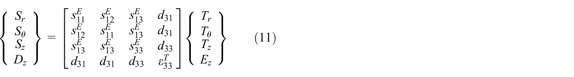
The constitutive equations for piezoceramics (such as lead zirconium titanate (PZT)) which have symmetry about the 3-axis and with electrodes covering the faces parallel to the 1–2 plane and poled through the 3-direction are given by
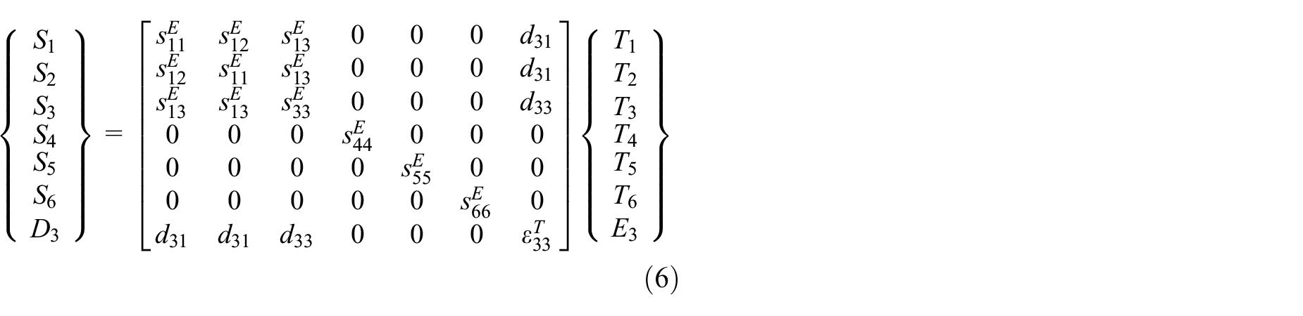
where Si are the strain components, Ti denote stress components, D3 denotes electric displacement, E3 denotes electric field, sij denote elements of the compliance matrix, dij denote the electromechanical coupling terms, and ε33 is the dielectric constant. The superscript E denotes that the terms are evaluated at constant electric field and the superscript T denotes that the term is evaluated at constant stress (i.e. stress-free state).
Equation (6) can be written in matrix notation as

Here, the t superscript is the matrix transpose operation.
After some manipulation, these equations can be rewritten as
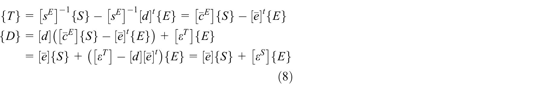
where

The percentage decrease in capacitance from the free to the blocked cases is then given by
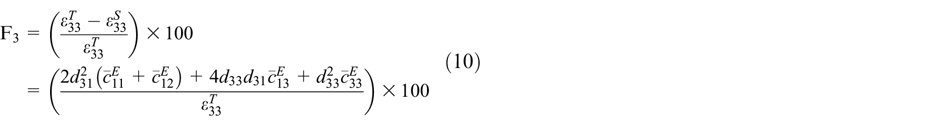
The material properties and the percentage decrease in capacitance (F3) for various fully blocked ceramic piezoelectric materials are given in Table 1. Note that plastic-based piezoelectric materials (such as polyvinylidene difluoride (PVDF)) are not considered since these materials tend to have relatively low electromechanical coupling and thus their blocked capacitance will not be significantly different from their free capacitance. As an example, using the PVDF properties provided by Odegard (2004), the reduction in capacitance for fully blocked PVDF is less than 2%.
Properties for various ceramic-based piezoelectric materials taken from Erturk and Inman (2011)a, Cao et al. (2004)b and Zhang et al. (2008)c and the associated percent reduction in capacitance between the free and blocked cases for the 3D case F3.
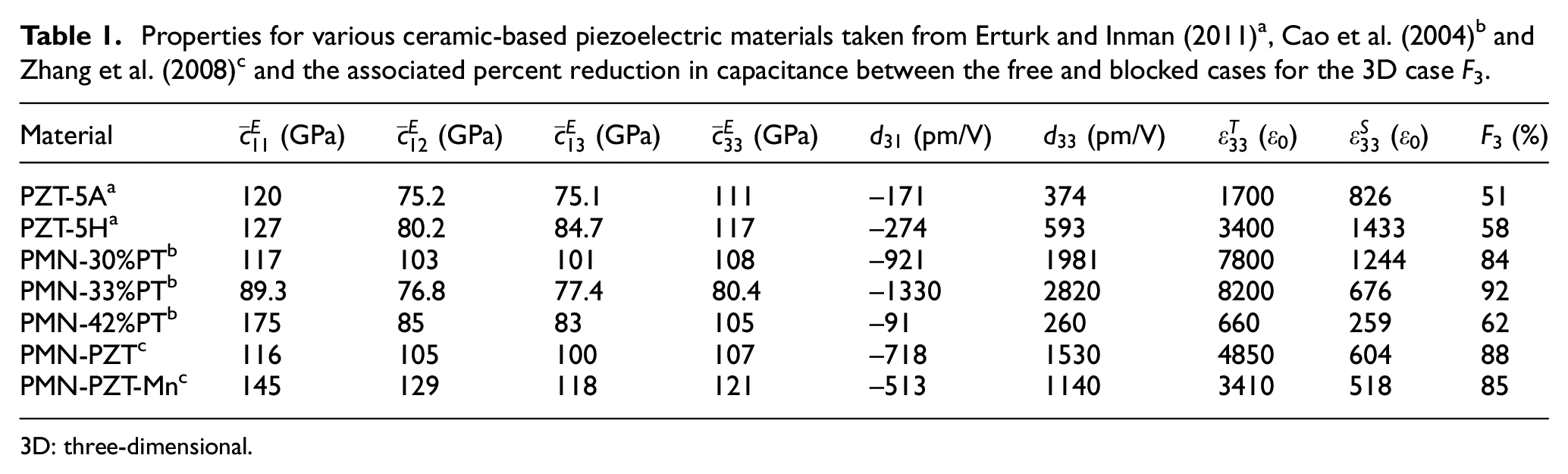
3D: three-dimensional.
The analysis is greatly simplified if the case of a thin embedded piezoelectric disk is considered. The constitutive equation (6) reduces to
where r, θ, and z are the radial, tangential, and thickness coordinates, respectively.
The plane-stress case (i.e. assuming that Tz = 0) further reduces the constitutive equation (11) to
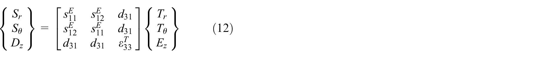
For this case, the percentage decrease in capacitance from the free to the blocked cases is given by
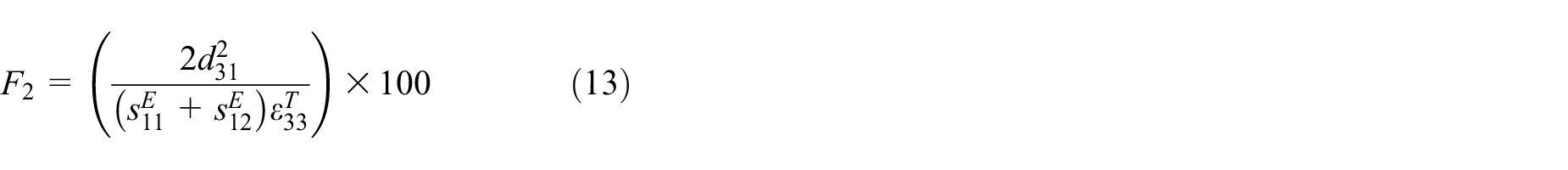
This two-dimensional (2D) percentage decrease in capacitance from the free to the fully blocked case (F2) is directly related to the planar coupling coefficient (kp) as defined by the IEEE standards on piezoelectricity, that is,
The reduction in capacitance for a thin disk that is fully constrained in the radial direction for several ceramic-based piezoelectric materials is shown in Table 2.
Properties for various ceramic-based piezoelectric materials taken from Erturk and Inman (2011)a, Cao et al. (2004)b, and Zhang et al. (2008)c and the associated percent reduction in capacitance between the free and blocked cases for the 2D case F2.
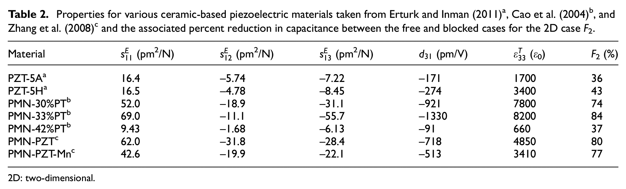
2D: two-dimensional.
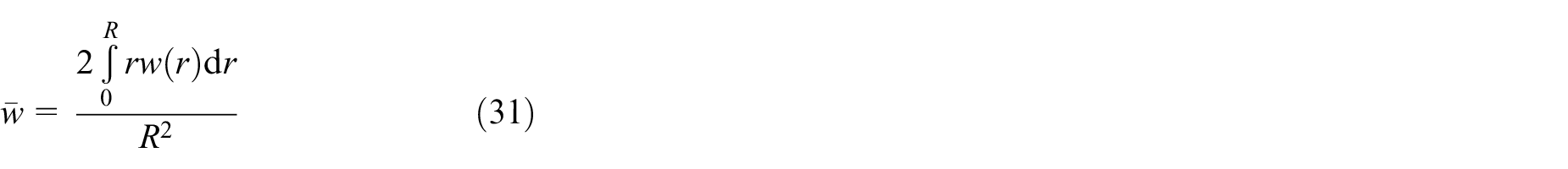
Piezoelectric disk embedded in an isotropic host matrix
Consider a piezoelectric disk as shown in Figure 1. The axisymmetric strain–displacement relationships are given by

where u and w are the radial and thickness displacements, respectively.
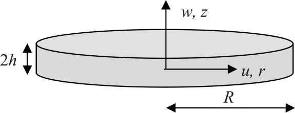
Piezoelectric disk with associated displacements, dimensions and coordinates.
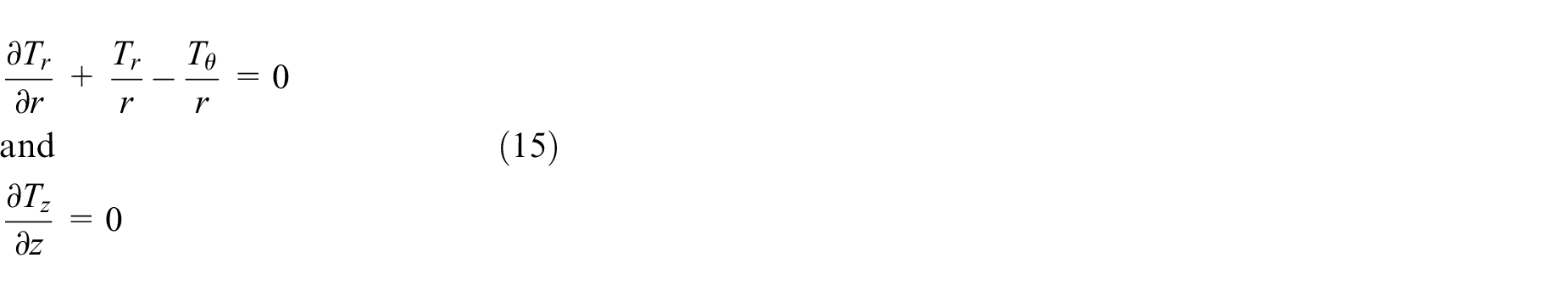
Equilibrium of a differential element in the r and z-directions, assuming no body forces, gives
Using the constitutive equations and the strain–displacement relationships gives
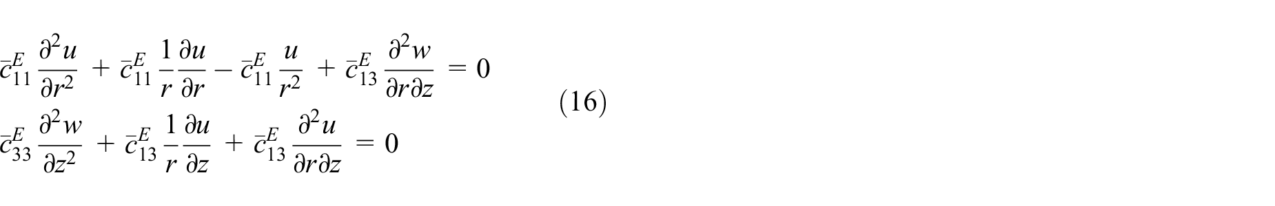
In the case when we assume that the radial displacement u is only a function of r and the thickness displacement w is only a function of z, equation (16) can be simplified to
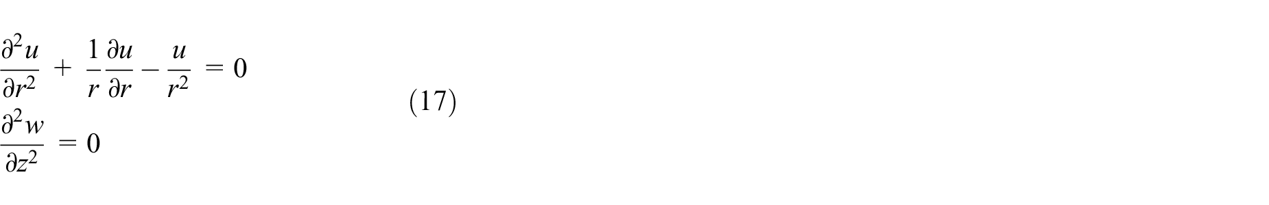
The solution of equation (17) is


where the A and B constants are determined from boundary conditions.
2D plane-stress case
Consider a piezoelectric disk embedded in a two-dimensional (2D) infinite isotropic host material with elastic modulus Ym and Poisson ratio ν as shown in Figure 2.

Piezoelectric disk embedded in a 2D axisymmetric host structure.
Using equation 18(a) for the piezoelectric, integration constant A2 must be zero since the displacements must be finite within the disk

where the subscript p denotes piezoelectric. For the matrix material, A1 must be zero since the displacements must be zero as

where the subscript m denotes host material.
At the interface between the piezoelectric and host, that is, r = R, the displacements must be equal so

Substituting equations (20) and (21) into the displacement–strain relationship and the plane–stress constitutive equation for the piezoelectric disk gives

The non-piezoelectric equation for the host material gives

The radial stresses at the piezoelectric–host interface must be in equilibrium giving

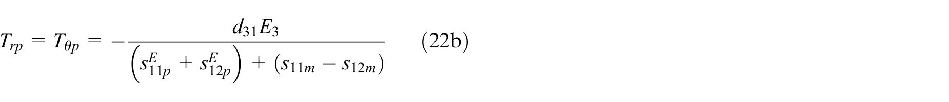
The electric displacement is then obtained as
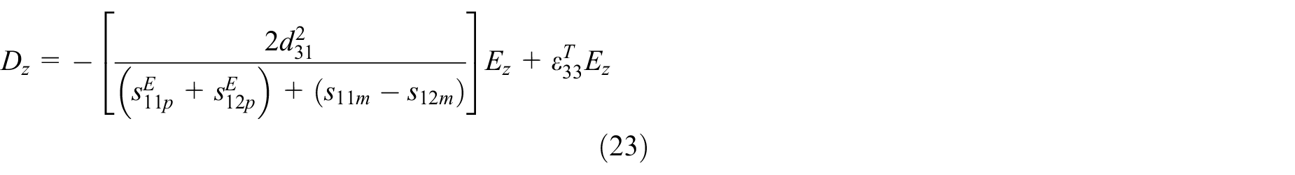
where the term in the square bracket is the reduction in free capacitance due to the constraint provided by the host material. The percent reduction in capacitance
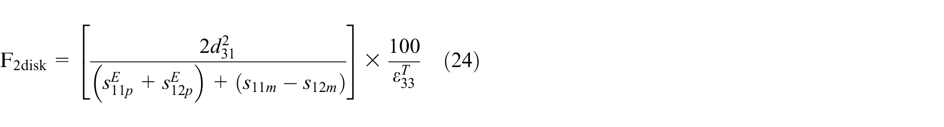
For an isotropic host material

As the shear modulus Gm of the host material increases to infinity, it is readily shown that the reduction in free capacitance (equation (25)) is equivalent to the fully blocked piezoelectric capacitance (i.e. equation (13)). The percent decrease in capacitance
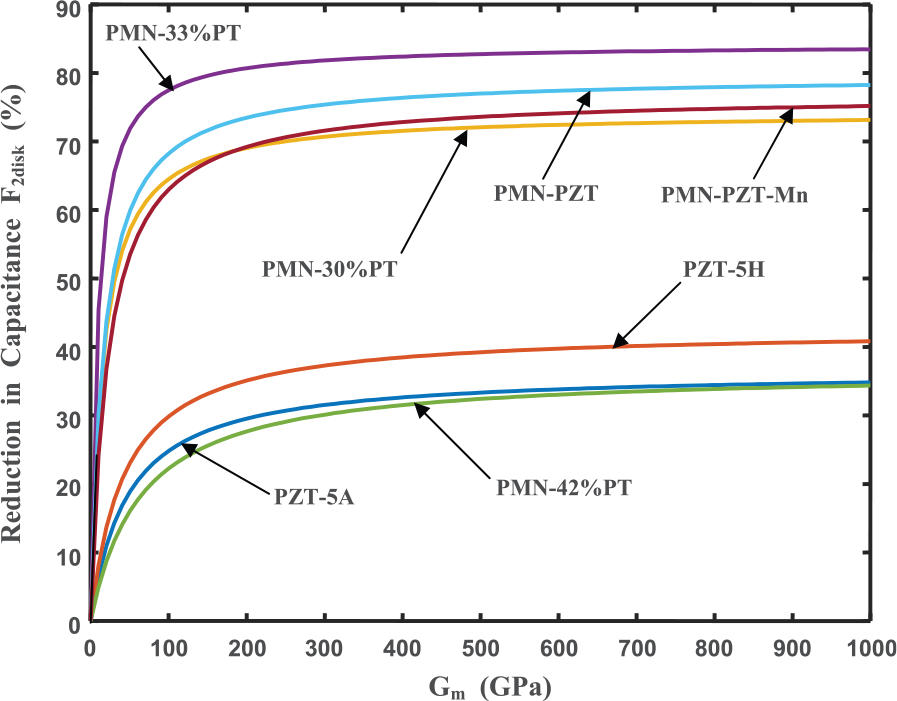
Reduction of free capacitance as a function of host material’s shear modulus for various piezoceramics for a plane-stress axisymmetrically confined disk.
3D axisymmetric case
Consider a piezoelectric disk embedded in an isotropic host material of infinite extent with elastic modulus Ym and Poisson ratio ν as shown schematically in Figure 4.
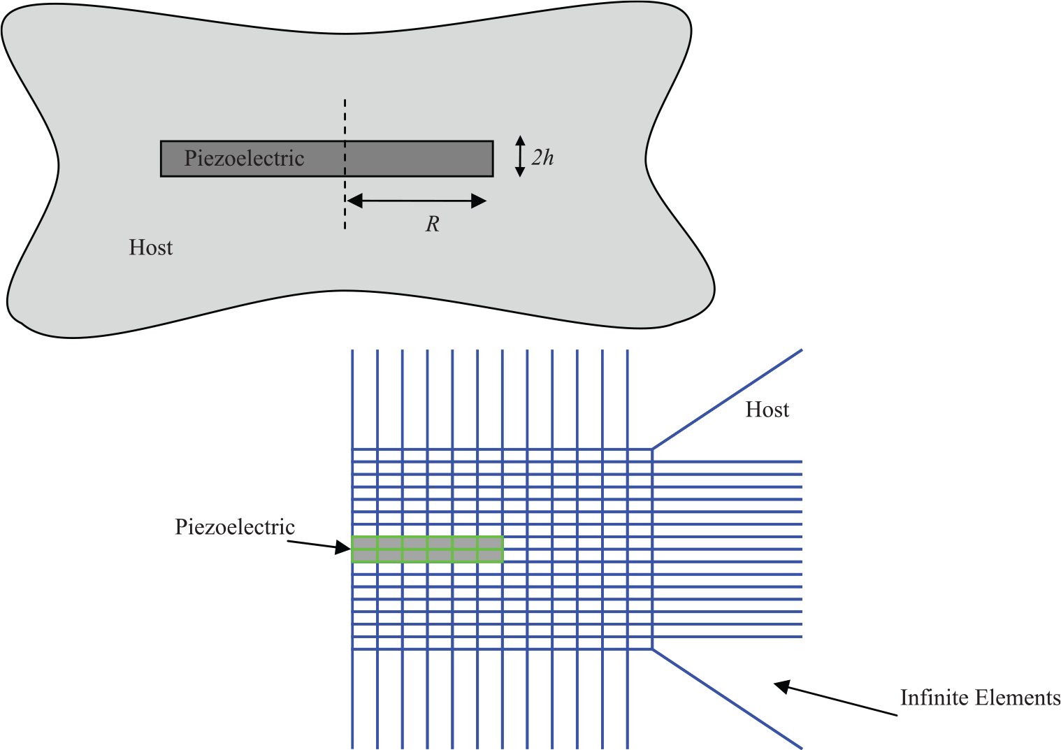
A piezoelectric disk embedded in an infinite host material (top) and the schematic axisymmetric finite element mesh with infinite elements (bottom).
The axisymmetric stress distributions for an embedded piezoelectric disk were calculated using a finite element model (FEM) with infinite elements on the boundaries as shown in Figure 4: quadrilateral, axisymmetric elements were used throughout the model. The model was implemented in ABAQUS (ver. 6.11; Dassault Systemes) using linear four-node elements for the piezoelectric material, host material, and the infinite elements. The top and bottom surfaces of the piezoelectric were constrained to have the same electric potential with a V = 1 V potential difference applied between the top and bottom electrodes. The piezoelectric disk was assumed to have a diameter of 2R = 6 mm and thickness of 2h = 0.2 mm.
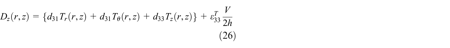
The calculated induced stresses (Tr, Tθ, and Tz) in the piezoelectric material were then substituted into equation (6) to give
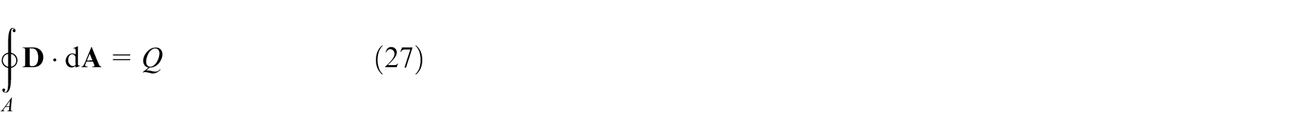
For a parallel plate capacitor, the charge is related to the electric field using Gauss’ law applied to one of the electrodes
where
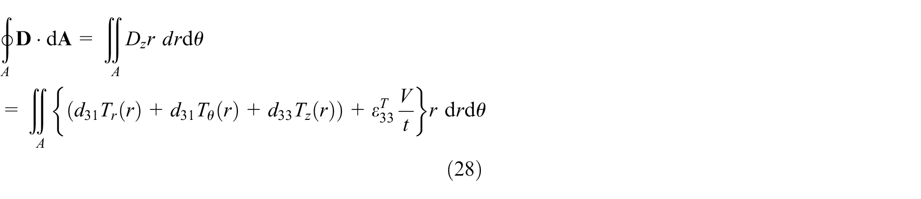
The capacitance for an axisymmetric piezoelectric disk is then
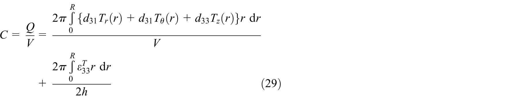
Here, the second integral represents the free capacitance, while the first integral represents the effect of the constraint on the capacitance. To calculate this integral, the stresses (Tr, Tθ, and Tz) as calculated by the finite element computation were extrapolated to the surface nodes of the piezoelectric material, and a numerical integration method (trapezoidal rule) was used to calculate the first integral.
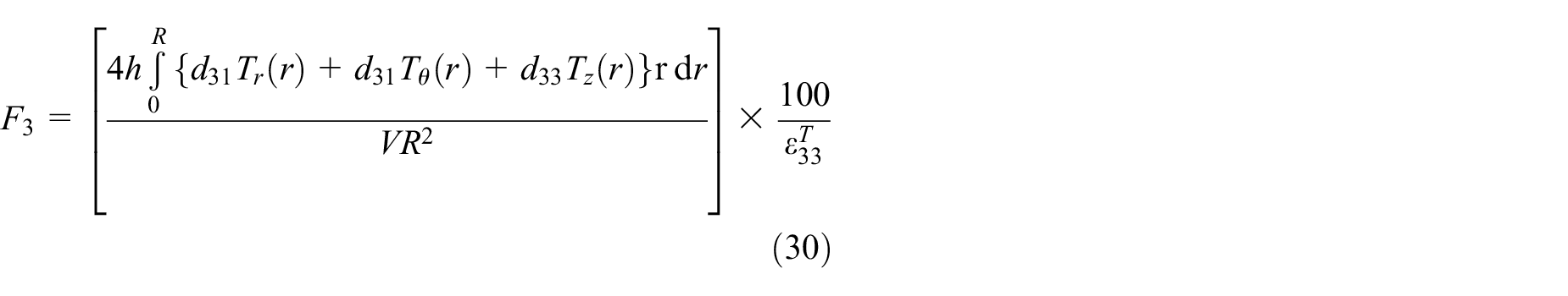
The piezoelectric material properties for the seven piezoceramics studied in this article can be found in Tables 1 and 2. The elastic modulus of the isotropic host material was varied between Ym = 0.1 and 1000 GPa, while the Poisson ration ν was kept at 0.3. Convergence of the finite element results was checked by increasing the mesh density until no significant change (less than 0.5%) was found in the reduction in stress-free capacitance (F3), that is
The reduction in stress-free capacitance for the fully embedded piezoelectric disk in an isotropic matrix with increasing elastic modulus for all piezoelectric materials in Table 1, as calculated by the finite element method, are shown in Figure 5. As expected, for all cases as the host structure’s modulus increased, the decrease in capacitance approached the fully blocked (strain-free) capacitance values as calculated in Table 1.
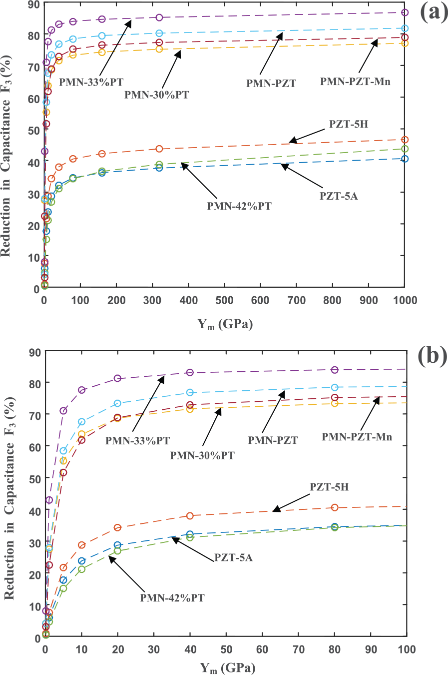
(a) Reduction of free capacitance of 3D embedded piezoceramic disks as a function of host material’s elastic modulus and (b) detailed view of the same data.
It should be noted that the integral in the reduction in stress-free capacitance (F3 in equation (30)) is the sum of the average induced stresses (
Figure 6 shows the stresses (
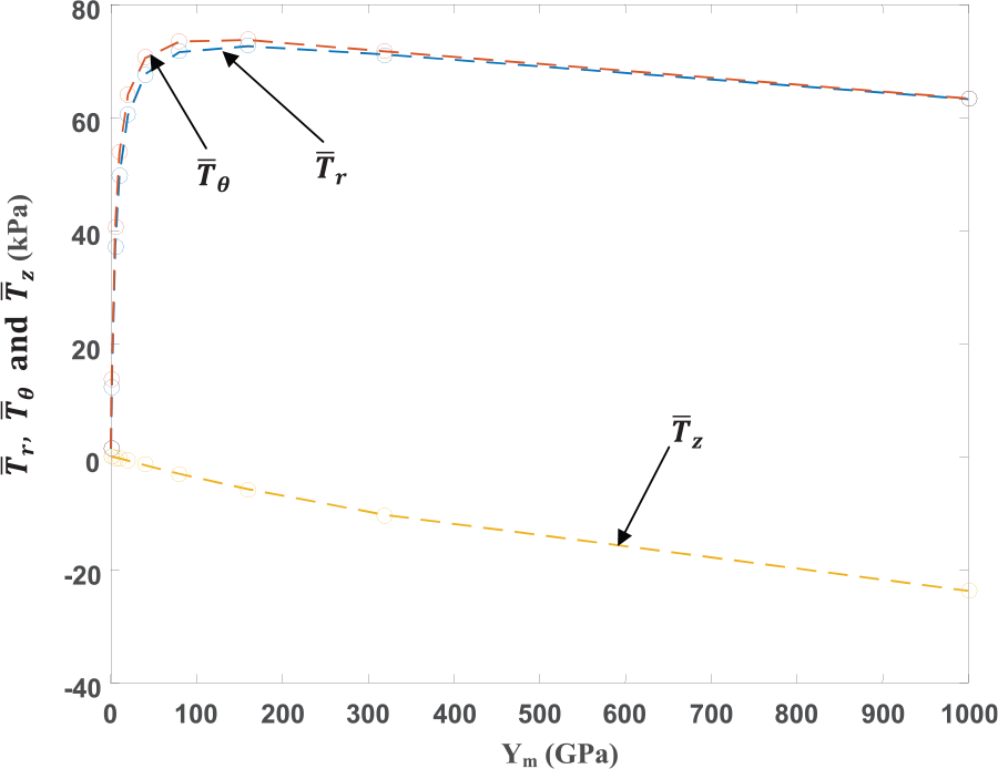
Average surface piezoelectric stresses (
For all seven piezoelectric materials, the reduction in free capacitance (F3) converges to the fully blocked capacitance (as given in Table 1). The initial decrease in free capacitance (for relatively low host material elastic moduli) is very rapid but reduces at a significantly slower rate for higher elastic moduli of the host.
Equivalent spring model
Giurgiutiu and Zagrai (2000) used radial springs to model the effect of the bonding layer for a piezoelectric disk surface mounted to a host structure. Here, we propose to extend the equivalent spring model to include not only the radial spring (kr) but also the vertical spring (kz) for an embedded piezoelectric disk (as shown in Figure 7). The stiffness of the infinite domain in the radial and thickness directions are modeled as single springs. The approach adopted in this article is similar to the calculation of the stiffness of “soil springs” used in foundation engineering (Gazetas, 1991) in which the semi-infinite soil domain is modeled as a set of translational springs. The equivalent stiffness of the embedding material is found from the finite element method and is dependent on the material property of the isotropic host material as well as the dimensions of the piezoelectric disk.
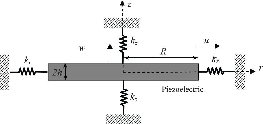
Equivalent spring model for an embedded piezoelectric disk.
Vertical spring stiffness
The vertical spring stiffness (kz) was calculated by applying a uniform vertical pressure (qz) to the axisymmetric FEM of the cavity representing the piezoelectric disk in an infinite domain as shown schematically in Figure 8(a). In this model, the half height of the cavity (h) is assumed to be significantly smaller than the cavity radius (R), that is h < R/6. The vertical displacement of the top of the cavity w(r) was then extracted from the FEM. The average displacement of the top of the cavity was calculated numerically from the following integral
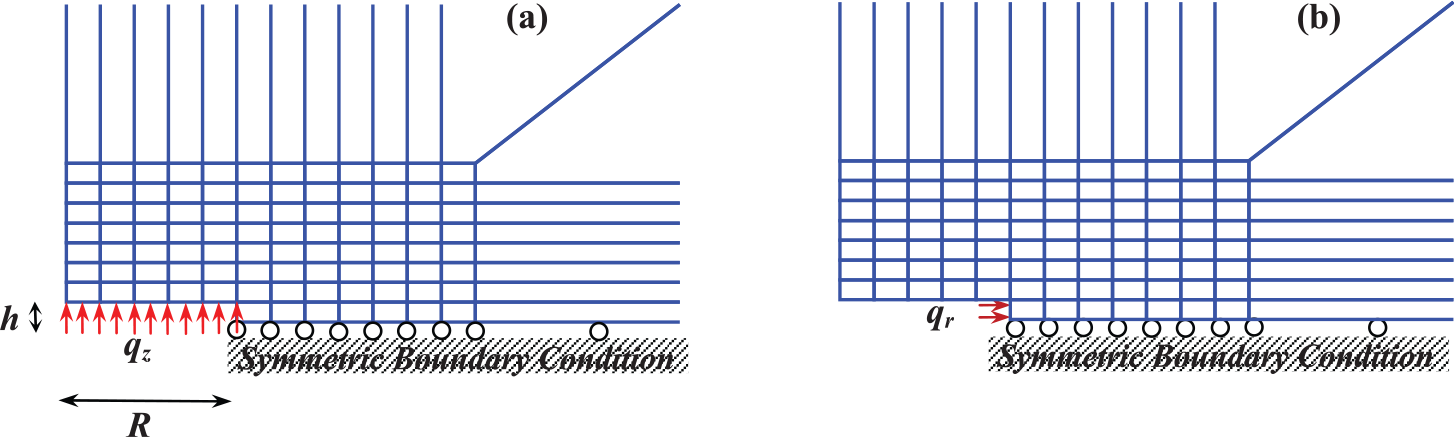
(a) Schematic of the FEM used to calculate the vertical equivalent spring stiffness and (b) the radial equivalent spring stiffness.
The simulation was performed over a range of cavity radii (R from 2 to 5 mm), cavity half heights (h from 0.1 to 0.3 mm), and several Poisson ratio (ν = 0.2, 0.3, and 0.45).
These simulations showed that the average vertical displacement

The average displacement is almost independent of the height of the cavity. The vertical displacement when h = 0 is equivalent to the well-known elasticity solution of the pressurized penny-shaped crack (Sneddon, 1946) given by
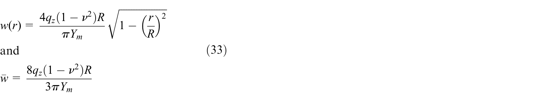
Thus, the average displacement of the penny-shaped pressurized crack is almost exactly the same as calculated from the FEM (equation (32)).
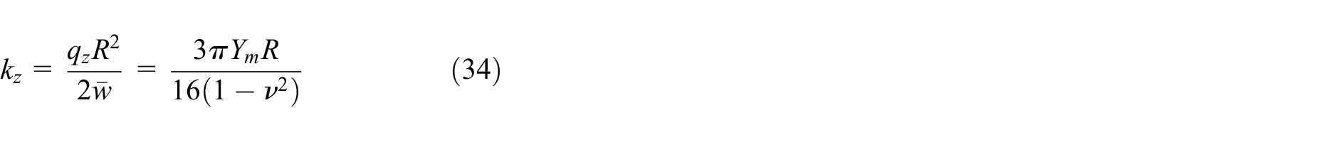
The equivalent vertical spring stiffness (kz) acting over an axisymmetric angle of 1 radian is then given by
Horizontal spring stiffness
The radial spring stiffness (kr) was calculated by applying a uniform radial pressure (qr) to the FEM as shown in Figure 8(b). Again the half height of the cavity (h) is assumed to be significantly smaller than the cavity radius (R). The average radial displacement (
Again, the simulations were performed over a range of cavity radii (R from 2 to 5 mm), cavity half heights (h from 0.1 to 0.3 mm), and Poisson ratios (ν = 0.2, 0.3, and 0.45).
These simulations showed that the average radial displacement

The equivalent radial spring stiffness (kr) acting over an axisymmetric angle of 1 radian is then given by

Equivalent spring model equilibrium
The equilibrium of a 1 radian segment of the equivalent spring model (as shown in Figure 7) is considered now. Equilibrium in the radial direction requires that at r = R

and

From equations (17) and (19),
Equilibrium in the z-direction requires that at z = h

and

Equations (37) and (38) are then solved simultaneously to obtain the unknown coefficients A1p and B1p. The equivalent spring stiffnesses (kz and kr) are taken from equations (34) and (36), respectively. These coefficients can then be substituted into equations (37) and (38) to find the stresses Tr and Tz.
The comparison of the average radial and z-stresses (
Piezoelectric stresses (
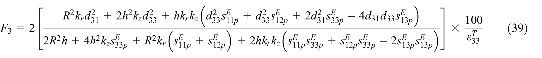
The system of linear equations given by equations (37) and (38) can be solved analytically. After algebraic manipulation, the reduction in capacitance of the embedded piezoelectric disk (F3) due to the radial (kr) and thickness (kz)-equivalent spring stiffnesses is given by the following closed-form expression
A comparison of the reduction in the stress-free capacitance (F3) as calculated by the finite element computation and by the equivalent spring model (i.e. equation (39)) is shown for PZT-5A, lead magnesium niobate (PMN)-PZT, and PMN-33%PT in Figure 10. (For clarity, the other piezoelectric materials are omitted.)
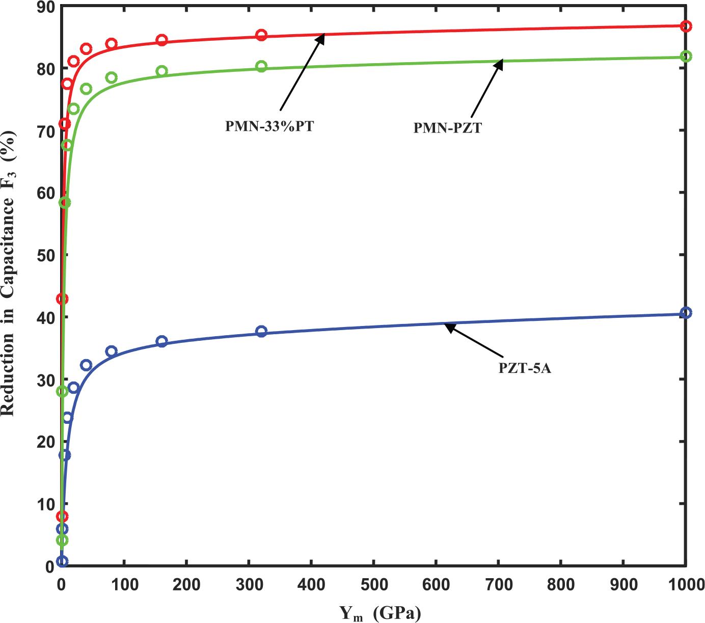
Reduction in free capacitance as a function of host material’s elastic modulus for various piezoceramics for a 3D embedded disk. The circles represent the finite element results and the lines represent the results of the equivalent spring model.
The equivalent spring model shows good agreement with the FEM for predicting the reduction in stress-free capacitance (F3) for a wide range of elastic moduli of the host material and for a wide range of piezoelectric properties.
Implications of the finite element and equivalent spring model
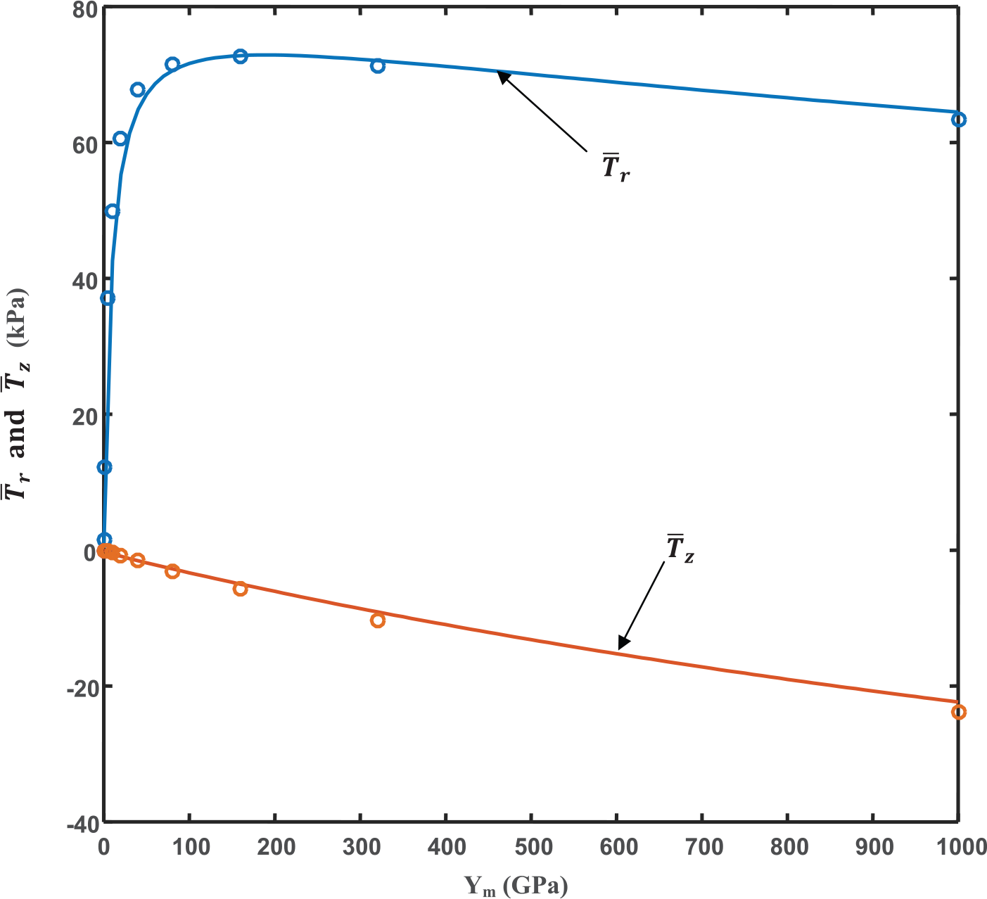
The results from the FEM (Figure 9) clearly shows that for relatively low values of the host materials’ elastic modulus, the thickness direction (i.e. z-direction) stresses are significantly smaller than the radial and circumferential stresses (i.e.
(a) Piezoelectric stresses (
In this case, equation (39) reduces to
Further inspection of equation (39) shows that the approximation of the reduction in embedded capacitance given by equation (40) is due to the assumption that h≪R (for example, 2h < 0.1R, that is, a thin disk) and thus all terms in h (except for the R2h term in the denominator) in equation (39) are small. The R2h term is relatively large since it is not multiplied by either the electromechanical coupling terms (dij) or by the piezoelectric compliance terms (sp) which tend to be very small. It is clear that all the neglected terms in h are coupled with kz in equation (39) and thus explain why kz = 0 for the simplified spring stiffness model. This assumption would break down for thicker piezoelectric disks or when the electromechanical coupling or piezoelectric compliance terms are large. The simplified model also breaks down for larger values of kr and kz. This explains why the simplified model with kz = 0 begins to break down at higher values of host material’s elastic modulus as shown in Figure 11(b).
Initial experimental results
Electrical wires were soldered to both surface electrodes of square piezoelectric patches (PZT-5A with dimensions of 7.5×7.5×0.126 mm, poled through the thickness from Piezo Systems Inc.). One patch was embedded in an epoxy resin cylinder (EPON 828 from Momentive Inc.) approximately 100 mm in diameter and 40 mm in height. A second piezoelectric patch was placed within a machined indentation on the surface of a 300×25×6.4 mm aluminum beam. The indentation was created by milling a volume of approximately 7.4×7.4×0.126 mm and then sequentially increasing the width and breadth of the slot in increments of 25 µm until the piezoelectric patch could just fit the machined area. Since the piezoelectric ceramic is a brittle material, special care was taken not to force the patch into the machined indentation. Small 1 mm holes were milled into the four corners of the machined area in order to relieve stress concentrations in the piezoelectric patch and to allow for access of the electrical cables. A small amount of EPON 828 epoxy was used to fill any gap between the metal and ceramic patch and to ensure that there was no electrical shorting between the electrodes of the piezoelectric. A third piezoelectric patch was embedded into a steel beam using the same procedure as for the aluminum beam.
During curing of the epoxy (which typically lasts 24 h for initial curing and 7 days for full curing), the capacitance of the piezoelectric transducer was measured using a capacitance meter (Keithley 2110), and the data were collected using a data acquisition system (NI-PXI from National Instruments) acquiring data at one sample every 2 s. The schematic of the experimental setup is shown in Figure 12.
Experimental setup for measuring the capacitance of an embedded piezoelectric transducer.
It should be noted that square patches were used in the experiments because of their availability in the relatively thin dimensions (approximately 0.1 mm thickness) required in this work.
The mechanical properties of the epoxy were measured by casting ASTM standard Type-I tensile test coupons and the elastic modulus was measured to lie between 3 and 3.8 GPa (which is as expected for epoxy resins). The material properties for the specimens and piezoelectric patch taken from the literature are given in Table 3.
Mechanical properties for the materials used in the experiments taken from Erturk and Inman (2011)a, Piezo Systems Inc. (2017)b, and Giurgiutiu et al. (1995) and O’Brien et al. (2007)c.
The rest of the values are commonly used elastic properties for aluminum and steel.
The curing histories of the normalized capacitance (i.e. current capacitance/initial capacitance—C/Co) of the three cases are shown in Figure 13.
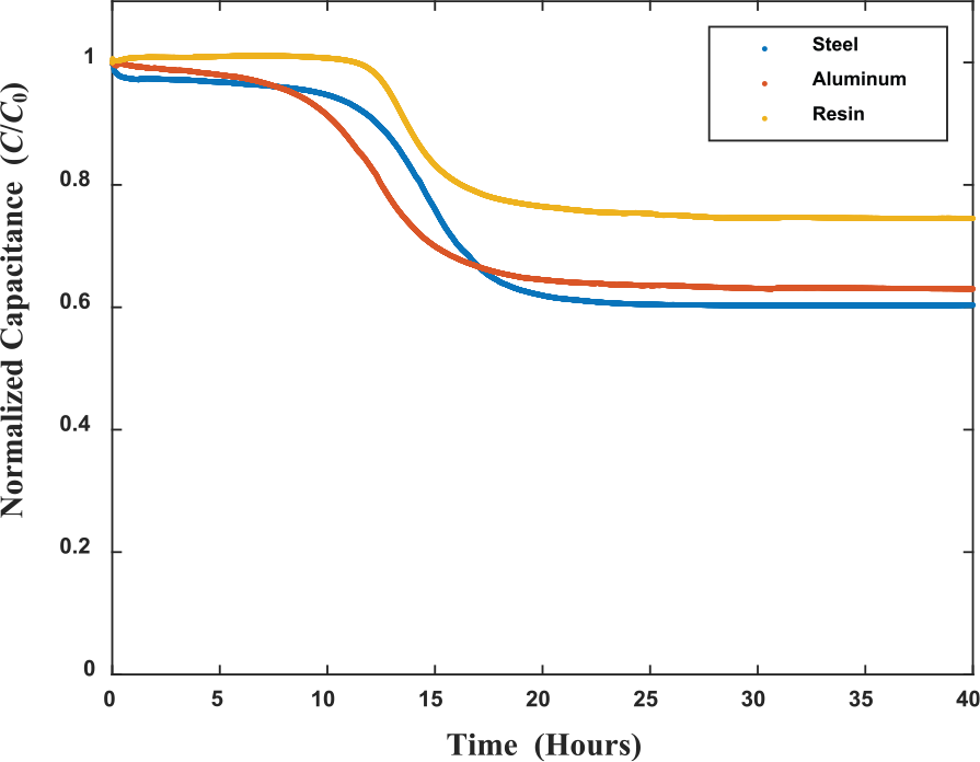
Reduction in normalized capacitance due to curing of epoxy of the three experimental cases.
The piezoelectric material patch properties and dimensions were used to find the reduction in capacitance using the derived 2D and 3D equivalent spring models for various values of host modulus (Ym). The Poisson’s ratio of the matrix was assumed to be 0.33 (the average value of the experimental host materials).
The initial experimental results cannot be compared directly to the predicted values for the following reasons: (1) the use of square patches in the experiment and the disk shape assumption used in the derivation; (2) for the aluminum and steel experimental cases, the piezoelectric is neither strictly embedded in 2D nor in 3D; (3) the model does not take into account the epoxy used to fill the gaps between the piezoelectric and the metals; and (4) the holes required for stress relief and electrical wire access.
For all three experimental cases, axisymmetric finite element analyses were performed. The piezoelectric disk was assumed to have a radius of 4 mm and a thickness of 0.126 mm. It was embedded in an infinite domain (for the epoxy) and embedded just below the surface in a 12.5 mm radius by 6.4-mm-thick ring for the aluminum and steel cases. The reduction in the capacitance values was calculated using both the finite element procedure described above and the equivalent 2D and 3D spring models. The results are compared to the experimentally measured values in Figure 14.
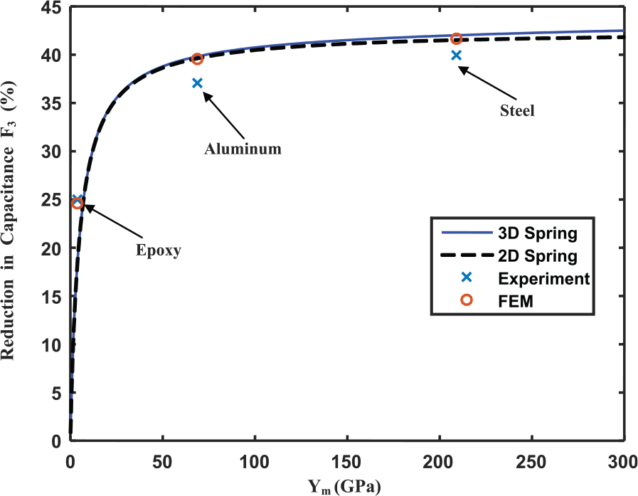
Comparison of the reduction in capacitance with increasing elastic modulus between the experiment, spring models, and the finite element model (FEM).
The experimental and computational results show relatively good agreement. The 2D and 3D spring models predict nearly the same reduction in capacitance over the entire modulus range. Furthermore, the FEM results show little variation between a piezoelectric disk embedded just under the surface and one fully embedded within an infinite medium. There is a larger variation between the FEM and experimental results for the aluminum and steel cases than for the epoxy case which is probably due to the presence of the small glue layer between the metal matrix and the piezoelectric material.
Since in practice the piezoelectric material is never embedded into a structure of infinite extent, one major question is to study the effect of the structural far boundaries on the reduction in capacitance. Piezoelectric elements are likely to be embedded into relatively large but thin structure (such as beams and plates); the effect of reducing the thickness of the host structure on reduced capacitance is discussed next. A similar finite-element disk model as presented previously for the metal experiments (i.e. with initial host dimensions of 12.5 mm radius by 6.4 mm thickness, PZT-5A properties given in Tables 1 and 3, and PZT dimensions of 4 mm radius and 0.126 mm thickness) and with the piezoelectric embedded at mid-thickness is used. The thickness of the host disk (H) was progressively reduced from 6.4 to 0.42 mm. The calculated reduced capacitances (F3) versus the material disk height (H) normalized by the thickness of the piezoelectric (2h) are shown in Figure 15. The dashed lines show the reduced capacitance for the PZT disk embedded in three different materials of infinite extent.
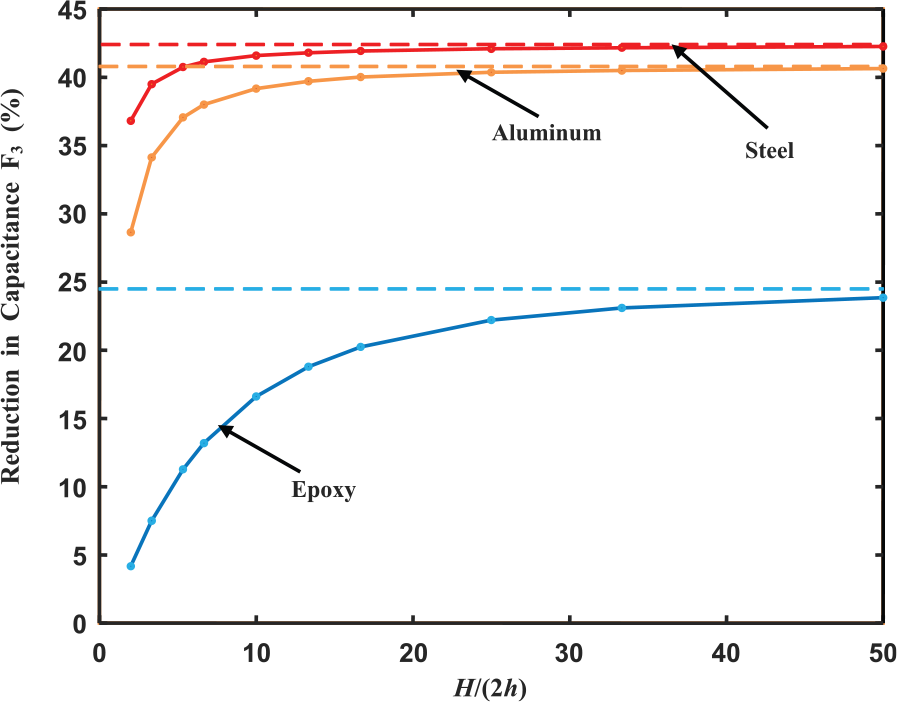
Calculated reduction in capacitance for a PZT-5A disk embedded in a finite disk as a function of disk thickness (H) for three materials (epoxy, aluminum, and steel). The dashed lines indicate the reduction in capacitance assuming infinite boundaries.
Figure 15 clearly shows that the far-boundary effect is dependent on the elastic modulus of the host material and that a stiffer host material can have a closer far boundary and still be considered infinite as compared with a softer material. To satisfy the thin disk assumption assumed in this work, 2h < 10H should be a reasonable limit for stiffer materials (such as aluminum and steel) but could be as small as 2h < 40H for softer materials (such as epoxy).
Conclusion
Constrained piezoelectric materials experience a decrease in capacitance when embedded within a host material. This decrease is dependent on a number of factors including the dielectric constant of the material, the electromechanical coupling of the piezoelectric, the stiffness of the piezoelectric material, the stiffness of the host material, and the geometry of the piezoelectric transducer. In general, the decrease in capacitance (as a percentage of the original capacitance) is strongly dependent on the electromechanical coupling coefficient (approximately to
Relatively accurate predictions of the decrease in capacitance of a piezoelectric disk embedded in an isotropic elastic medium can be obtained using an equivalent spring model. In this model, springs are placed in the radial and thickness directions of the disk to take into account the assumed infinite extent of the host material. Finite element simulations have shown that the radial spring stiffness (kr) and thickness spring stiffness (kz) are functions of the piezoelectric material disk geometry (i.e. radius R and height h) as well as the elastic modulus (Ym) of the host material. The stiffness of both these springs is only slightly affected by the Poisson ratio (ν) of the host material. The equivalent spring stiffness approach not only provides a relatively simple and accurate approximation of the reduction of capacitance of a piezoelectric embedded in a host matrix, but also provides some valuable insight into the overall behavior of the system. For example, the equivalent spring stiffness shows that for piezoelectric disks embedded in soft host materials, the effect of the radial springs dominates over the effect of the thickness springs for thin disks.
Preliminary experimental results show good agreement with the developed theory. There are of course some major differences between the experiments and the theoretical/computational models which include the following: (1) square piezoelectric materials were used in the experiments instead of the disk shapes used in the theoretical derivation; (2) in two of the experimental cases (aluminum and steel), the piezoelectrics were not fully embedded in the host material but were embedded just below the surface; and (3) in two experimental cases, a small gap was left between the piezoelectric and the host structure that was filled with a much softer epoxy resin. Though more detailed experimental validation is required in future work, the experiments do serve to highlight some important practical issues when embedding piezoelectric materials. At present, the most practical method of embedding piezoelectric materials is by casting (as done for polymer and cement-based composites). True embedding within metallic or ceramic hosts poses severe challenges in protecting the piezoelectric material both from extreme temperatures and from possible damage during production. (This issue might become less of a problem in the future with new advances in additive manufacturing techniques). In all embedding, it is difficult to ensure that voids do not form around the transducer during manufacturing. These voids would reduce the average effective modulus of the surrounding host as likely to have occurred in the embedding of the transducers in the present metallic experiments. A related problem is the routing of the electrical wires from the transducer to external electrical circuits. Not only must the wires be protected during manufacturing and in service, but the presence of these wires changes the constraint of the host on the piezoelectric element. The finite element results showed that there is only a small reduction of capacitance between a piezoelectric transducer that is fully embedded and one that is embedded just below the surface of the host material.
It must be emphasized that when the host’s elastic modulus is greater than 50 GPa, the simulations predict more than an 80% reduction in embedded capacitance for certain single-crystal piezoelectrics (PMN-33%PT). Though the same piezoelectric material shows a reduction greater than 90% for fully blocked capacitance (as presented in Table 1), such a high value would be difficult to achieve with practical host materials for which elastic modulus would have to be greater than 1000 GPa. Such large decreases in capacitance would result in approximately one order of magnitude increase in generated power. Future work should concentrate on experimental confirmation of these results.
Footnotes
Declaration of conflicting interests
The author(s) declared no potential conflicts of interest with respect to the research, authorship, and/or publication of this article.
Funding
The author(s) disclosed receipt of the following financial support for the research, authorship, and/or publication of this article: The work described in this paper was supported by the PSC-CUNY award program.