
Abstract
A biomimetic vibration sensor to sense external vibrations was designed based on the hair receptor of insects similar to the water strider. Platinum core piezoelectric ceramic fiber body was prepared by squeeze and press method. This was followed by high-temperature sintering, surface electrode coating, and polarizing to fabricate the symmetric coated metal core piezoelectric fiber vibration sensor. A cantilever beam structure with two surface electrodes was designed as the theoretical sensor model. The fiber was fixed on a matrix structure. Experiments were performed to verify sensing characteristics under impact vibration and simple harmonic excitation. Results showed that the symmetric coated metal core piezoelectric fiber was able to sense amplitude and direction of impact vibration along with frequency, amplitude, and direction under simple harmonic excitation. Such a biomimetic vibration sensor can be effectively used to sense vibration amplitude and direction for a wide range of applications.
Introduction
Many animals use vibration to communicate or sense conditions in their surrounding environment. Insects such as sawflies that live on plants can communicate with each other based on vibrations generated by tapping on the plant stem (Hill, 2001). However, other insects use vibration to detect position of predators and preys (Cokl and Doberlet, 2003). Insects such as water strider and drum beetle make use of fluctuations along the water surface to communicate. Moreover, using vibrations generated over the surface, they can locate both direction and position of predators and prey (Son et al., 2014). A hair sensor is usually used in insects to sense vibrations (McConney et al., 2009). The structure of hair sensor typically consists of one straight and the other setaceous end. The latter stretches out of the body of the insect with the other end fixed on the cuticular membrane. This structure passes through the cuticular membrane and connects to a nerve cell. These hair-like structures are known as seta and as a whole form a cantilever beam-like structure (Perez Goodwyn et al., 2009). A surface wave passing the insect causes a bending deformation of the seta located on its body. This deformation is transferred to the nerve cell, which in turn produces a stimulation signal. These stimulations are then communicated to the brain, which interprets the signals (Han and Jablonski, 2010).
Artificial cilia sensors to sense vibration in the surrounding environment are currently being investigated (Tao and Yu, 2012) and development has been achieved by imitating the hair-like sensors in insects (Droogendijk et al., 2014). The fundamental structure of the artificial cilia sensor is similar to the structure of the hair-like sensor in insects. For the artificial cilia sensor, a thin cantilever beam is fixed at the base; vibration from external environment acts as external stimuli, which results in bending deformation of the cantilever beam. An energy transduction component changes this deformation into a sensing signal. The sensing signal is measured and analyzed to characterize the external environmental vibrations (Tao and Yu, 2012). Based on different positions of the sensing component on a cantilever beam, the artificial cilia sensor can be divided into two categories. The first has the sensing component installed at the base of cantilever beam. In this case, the cantilever beam does not have any sensing capabilities. However, vibration at the base results in the cantilever beam bending and deformation of the sensing component at the base. By measuring deformation of the sensing component, vibration signal at the base can be interpreted. The other sensor type employs different sensing materials in the fabrication of the cantilever beam. Vibration at the base results in bending deformation of the cantilever beam. This bending deformation is directly measured by the sensing components, subsequently allowing vibration parameters to be obtained.
Typically, capacitors and piezoresistive elements installed at the base of the cantilever beam can serve as sensing components. The capacitance-based method employs a miniature variable capacitor typically connected to the base of the beam. External vibrations are inferred by monitoring change in capacitance (Dijkstra et al., 2005). For the piezoresistive method, piezoresistive components are attached to the base of the vibratory transduction beam. Mechanical deformation at the base can be measured from the change in the resistance of the piezoresistive sensor (Engel et al., 2006; Liu, 2007). Several piezoresistive components can be installed surrounding the connection position of the cantilever beam and the base. Magnitude and direction of the vibration can be calculated from resistance change of several piezoresistive components (Chen et al., 2007; Zhang et al., 2008).
Piezoelectric materials have direct electromechanical transformation property (Jung and Roh, 1998). Typically, they can be used as energy transduction elements of the vibration sensor. If piezoelectric materials are used in artificial hair sensors, deformation of the cantilever beam can be directly measured, allowing external vibration information to be obtained (Zhou et al., 2015). In general, piezoelectric ceramics are used as the piezoelectric materials in artificial hair sensors. Structure of the hair-like piezoelectric ceramics sensor can be divided into the following two categories: with and without a core. Structure of the hair-like core type piezoelectric ceramics sensor consists of a layer of piezoelectric ceramics coated evenly around a circular metal core with a thin metal film on the surface of the piezoelectric ceramic. The metal core and the surface metal film can be used as two electrodes. Such a sensor can then be used to sense deformation along the length direction. This metal core piezoelectric ceramic fiber sensor was fabricated by the squeezing (Sebald et al., 2005; Takagi et al., 2006) and pressing method, using the multi-dip-coating process (Dolay et al., 2014) and the hydrothermal method (Lin and Sodano, 2009; Shimojo et al., 2007). Semi-electrode metal core piezoelectric fibers can be prepared by jet plating electrode along the half longitudinal surface of the metal core piezoelectric ceramic fiber (Qiu et al., 2010).
After sputtering a metal such as silver (Ag) on the surface of the cylinder-shaped coreless PZT (lead-based lanthanum-doped zirconate titanates) fiber, followed by photo etching, two longitudinal symmetrical surface electrodes were fabricated. This cantilevered PZT fiber could work as a displacement sensor, with an apparent direction sensing property (Tao et al., 2013). Due to the brittleness of the piezoelectric ceramic materials, the use of the PZT fiber is limited (Askari et al., 2006; Sato and Nagamine, 2005). In order to improve the mechanical strength of the fibers, metal core piezoelectric ceramic fibers were designed and manufactured (Sato et al., 2004). The metal core can enhance the mechanical strength and durability of the PZT fiber, thus expanding the application area of the fiber and increasing its life (Askari et al., 2006).
Based on previous studies reported in the literature (Bian et al., 2009; Bian and Qiu, 2011), in this article, the squeezing and pressing method to prepare metal core piezoelectric fiber (MPF) was discussed. Jet plating of the two electrodes was carried out to symmetrically coat the ceramic surface for fabricating a symmetric electrode metal core piezoelectric fiber (SMPF). Two surface electrodes and a metal core were used as the electrode to apply an electric field for partial polarization of the PZT. After polarization, connection mode of electrode was changed, and the two surface electrodes of SMPF cantilever beam structure were used as sensing electrodes. In this way, a single SMPF can be used as a vibration sensor. One SMPF was fixed on a matrix, so vibration amplitude and frequency of the matrix could be measured along with the vibration direction of the matrix. A theoretical model of this vibration sensor was established. Experimental results verified the sensing property of the SMPF.
Design and fabrication of an SMPF
Structure of the SMPF is shown in Figure 1. A metal core with a circular cross section was located in the middle. A piezoelectric ceramic material with uniform thickness surrounded the metal core. Cross section of the piezoelectric ceramic was circular plate-shaped, and the whole fiber was cylinder shaped. Two conductive layers (conductive Ag paste YH-A001) were coated symmetrically along the longitudinal surface of the fiber for use as surface electrodes. When an electric field was applied to polarize the piezoelectric ceramic, the two surface electrodes functioned as a single electrode and the metal core was used as the other electrode. Connection mode of the polarized circuit is shown in the left half of Figure 2. For the circular plate-shaped piezoelectric ceramics shown in Figure 1(b), the two fan-shaped piezoelectric ceramic regions with the surface electrodes were excited by a radial electric field to allow convenience of analysis. When the electric field was applied, the two regions of the piezoelectric ceramic resulted in the generation of piezoelectricity with polarization in the radial direction. Remainder of the piezoelectric ceramic without the electrode was not polarized and did not generate piezoelectricity. In a hair sensor based on piezoceramic fiber (Tao et al., 2013), the direction of polarization was found to be from one surface electrode to another surface electrode, which is different from the polarization direction of SMPF.
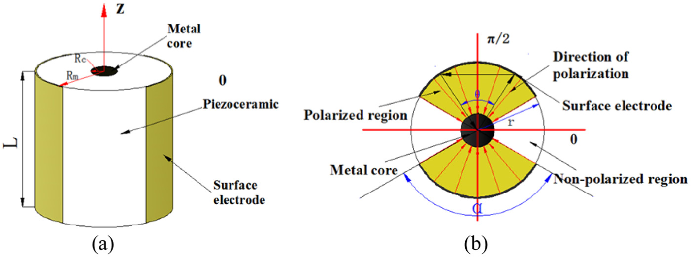
Structure of SMPF: (a) integral structure and (b) polarization and polarization direction on the cross section.
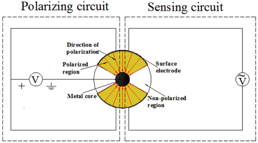
Polarizing circuit and electrode connection for the sensing circuit.
In the preparation stages, pretreated PZT powder and the metal core are put together into the mold as shown in Figure 3. A manual tablet press (FW-4 model; Tianjin Tianguang Optical Instruments Co Ltd) was used to extrude the ceramic body of the SMPF.
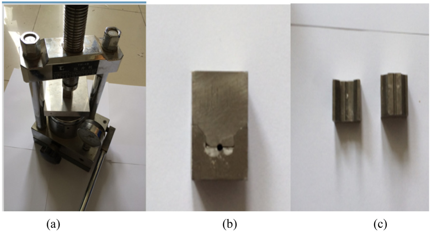
(a) The tablet press used to fabricate piezoelectric fiber and (b) the picture of the integral setup, and (c) the picture of the separated mold setup.
The preparation process using this molding method was relatively simple. No binding component or plasticizing agent was added to the ceramic powder. The compacted piezoelectric fiber body layer was placed flat wise in the corundum crucible, with PbTiO3 powder (weight ratio of PbTiO3 powder to volume of the crucible was 2.5 g L−1). Gap between the crucible and the cover was sealed with a ZrO2 plug. In the high-temperature sintering process, PbTiO3 powder produces a protective atmosphere in order to reduce volatilization of PbO in the body element. This crucible was then placed in an electric furnace. In the initial stage, the crucible was exposed to slow burning. After the temperature reached 600°C, fast firing glazes were applied. This method reduced volatilization of PbO in the sintering process and ensured that composition of the piezoelectric ceramic fiber was retained. After the temperature of the furnace reached 1200°C, this temperature was maintained for 2 h. This was followed by a cool down by switching off the power to the furnace. After the furnace cooled down to the room temperature, the PZT mold was removed from the furnace. As the sintering temperature was high, heat-resistant platinum was selected as the metal core. Figure 4(a) shows the scanning electron microscope (SEM) image of the fiber after sintering, indicating that the piezoelectric ceramic is annular and the platinum core is located in the center of the fiber.
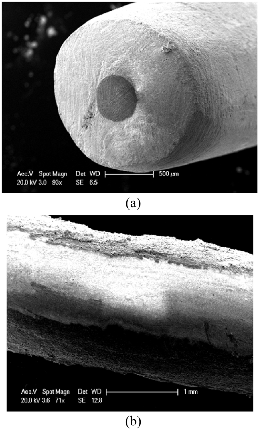
Prepared SMPF: (a) sintered fiber and (b) symmetrically coated two conducting layers on the longitudinal surface.
The conductive silver paste is symmetrically coated on the longitudinal surface of the piezoelectric ceramic fiber. After heating curing, the surface electrodes were formed and are shown in Figure 4(b). The fiber was immersed in silicone oil for polarization. The oil temperature was maintained constant at 120°C. From the left half of Figure 2, it can be seen that the connection mode of the polarized circuit was added with an applied voltage. This polarizing voltage was slowly increased to 2 kV mm−1. The voltage was kept constant for 30 min. Then, power to the silicone oil heater was turned off and polarizing voltage was kept constant. After the fiber in the silicone oil cooled down to room temperature, the polarizing power was turned off, and the polarization process was completed.
SMPF vibration sensor model
Herein, one end of the SMPF was fixed to the matrix and the other end was free, forming a cantilever beam structure. When the matrix is subjected to impact vibration or simple harmonic vibration, the SMPF can be used as a vibration sensor to sense vibration of the matrix as shown in Figure 5(a).
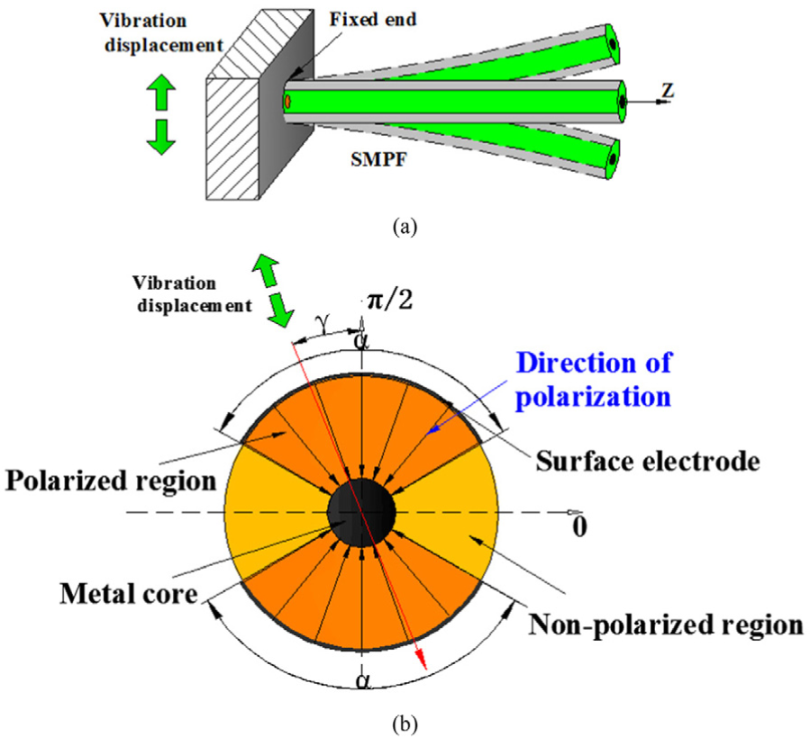
An SMPF used as the vibration sensor: (a) SMPF fixed on the matrix and (b) vibration direction.
If the matrix undergoes impact vibration, displacement is u(t) = U0(1 − e−τt)cos γ. Stress in the cantilever beam is equivalent to a uniformly distributed load, acting in a direction perpendicular to the length direction. This can be given as, F = τ2U0e−τt cos γ, where U0 is initial amplitude, τ is time constant, and included angle of γ as the shock excitation direction and the y-axis in the cross section as shown in Figure 5(b).
Electric charge is produced on the electrode surface due to piezoelectric effect. In the SMPF, piezoelectric equation in circular cylindrical coordinates for the polarization part of the circular piezoelectric ceramic can be expressed as follows


where S is strain, T is stress, D is electric displacement, E is electric field strength, sE is elastic compliance coefficient for a constant electric field, d is piezoelectric constant, and εT is dielectric constant for constant stress (Bian et al., 2009).
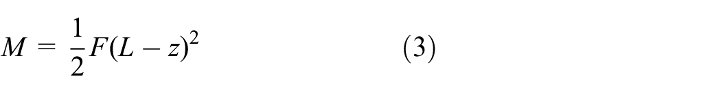
When the SMPF surface of the cantilever beam structure is subjected to a uniformly distributed load F, bending moment M produced is given as follows
To simplify calculations, it was assumed that SMPF could lengthen and shorten freely along the diameter direction. Length of SMPF was usually significantly larger than the diameter; therefore, stresses in the peripheral and tangential directions could be ignored. After the uniformly distributed load was applied, SMPF strain and boundary conditions of the electric displacement can be expressed as follows


where Dθ, Dz are the electric displacement, and Er is the electric field (Bian et al., 2009). The subscript notation for the strain S indicates the direction of polarization (first subscript) and direction of strain (second subscript).
By substituting equations (4) to (6) into equations (1) and (2)
where
As length of SMPF was significantly larger than the diameter, bend can be considered to be same as the radius of curvature (κ) for parts of SMPF along the axial direction and is given as follows
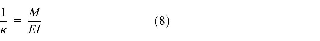
In the above-mentioned equation, E is elasticity modulus of the fiber, and I is moment of inertia of the fiber; EI is the flexural rigidity of cantilevered SMPF, which reflects the ability of the cantilever beam to resist the bending deformation, and
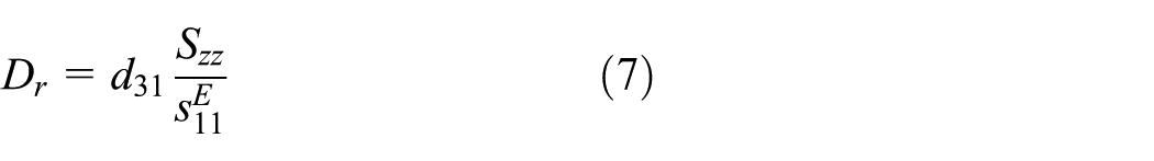
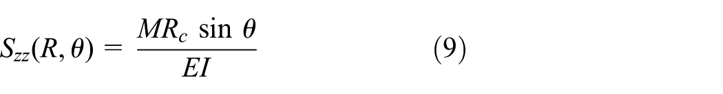
At the surface electrode, with Rc and θ of SMPF known, strain is given as
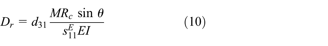
Equation (9) is substituted into equation (7) to obtain electric displacement
Electric charge on the surface electrode of the fiber is given as follows
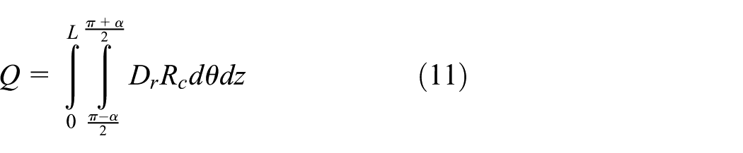
Substituting electric displacement in equation (10) into equation (11)
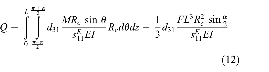
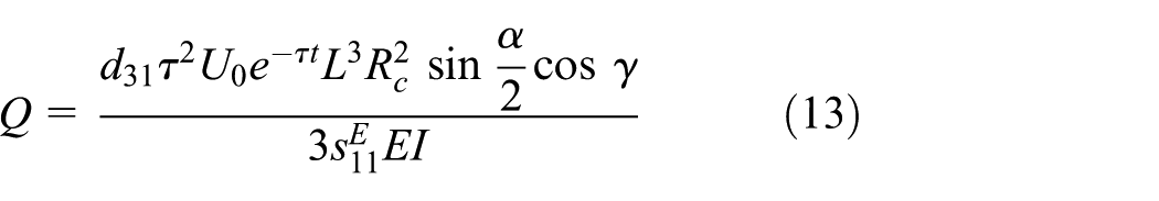
F = τ2U0e−τt cos γ is substituted into equation (12) to obtain impact vibration that the matrix undergoes. This is proportional to the electric charge produced at the surface electrode of SMPF
If the matrix undergoes simple harmonic excitation with a displacement, u(t) = U0 sin(ωt)cos(γ), SMPF is subjected to an equivalent force given as F =U0ω2 sin(ωt)cos(γ) (Jung and Roh, 1998), which is a dynamic and uniformly distributed load. F is substituted into equation (12) to obtain electric charge produced by the SMPF
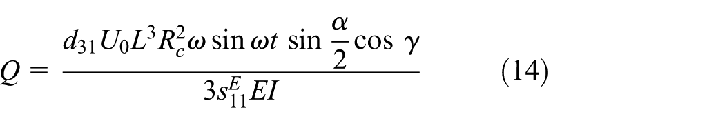
It can be observed from equation (13) that when the matrix undergoes impact vibration, SMPF produces an electric charge response. Magnitude of this electric charge was found to be proportional to the impact strength U0 of the matrix and has a cosine relationship with the angle γ. It can be observed from equation (14) that electric charge response of SMPF is a simple harmonic signal when the matrix undergoes simple harmonic vibration. In this case, frequency and vibration frequency of the matrix were the same. Amplitude of the electric charge was proportional to the amplitude of vibration U0 and has a cosine relationship with the angle γ.
The flexural resonance frequency of cantilevered SMPF, f, is defined as (Smits and Ballato, 1994: 480)
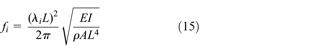
where λiL is flexural vibration characteristic value of the second order i of cantilevered SMPF, ρ is the equivalent density of SMPF, A is the cross-sectional area, and L is the length of SMPF. By substituting related parameters into equation (15), the flexural resonance frequency of cantilevered SMPF, fS, can be obtained as follows
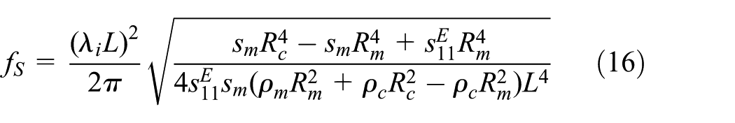
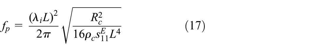
where ρm is the density of metal core and ρc is the density of piezoceramic. According to the literature report (Tao et al., 2013), the flexural resonance frequency of cantilevered PZT fiber, fp, can be obtained as follows
The density and the elasticity modulus of PZT are lower than those of platinum. Therefore, the flexural resonance frequency of cantilevered SMPF is lower than that of a cantilevered PZT fiber.
As the two surface electrodes on the SMPF were symmetrical, when the matrix underwent excitation, SMPF was subjected to symmetrical bending and deformation forces. This is due to electric charges produced on the two surface electrodes being equivalent to each other, but opposite in direction. The two surface electrodes were connected to a data acquisition card (PLCD-8710 WIRING TERMINAL BOARD REV.A1 01-3), and circuit connections were shown in Figure 2. The measured electric charge value was two times the electric charge on a single electrode. This circuit is simple, and the sensing signal is amplified and the sensitivity of the sensor is improved.
Results and discussion
In order to verify impact vibration sensing capabilities of SMPF, the fiber was glued and connected to one end of the beam of constant strength using an epoxy resin. Displacement was measured using a laser displacement sensor. The experimental setup is shown in Figure 6(a). Application of impact vibration to the whole beam was achieved by dropping a small iron pellet at a fixed location on the beam of constant strength. An electric charge signal produced by the SMPF passed through the charge amplifier, and the displacement signal was collected in real time using the data acquisition card.
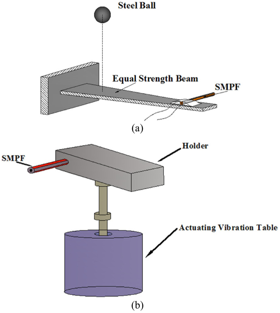
Experimental setup for SMPF vibration sensing for (a) impact vibration and (b) simple harmonic vibration.
When a small iron pellet is dropped from a fixed height onto the beam of constant strength, the beam undergoes impact vibration and causes impact deformation. The fixed end of the SMPF reaches maximum displacement within a very short time, as shown in Figure 7. After the impact, free vibration is observed for the beam. The vibration amplitude undergoes damping and displacement decreases with time. After a certain time, the beam returns to equilibrium position. SMPF on the beam senses this impact vibration and the output electric charge value reaches a maximum instantaneously with the vibration reducing over time until it returns to zero. Variation in the SMPF electric charge signal and displacement signal was found to be the same.
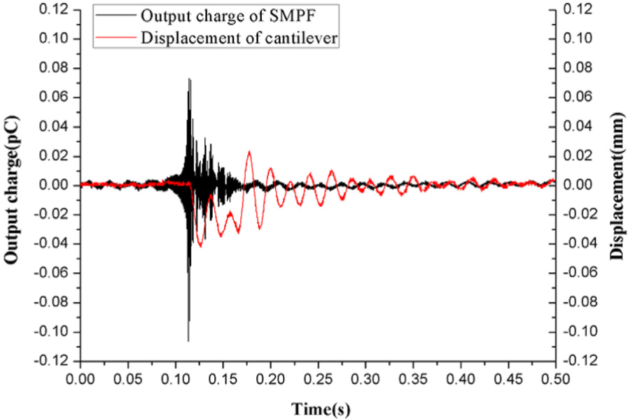
Electric charge response signal for SMPF impact vibration.
Experiments were conducted with the γ value remained unchanged. Change in the height from which the iron pellet was dropped resulted in changes in U0 in equation (13). Maximum displacement values of the beam for each impact and output maximum positive charge value of SMPF were measured and are shown in Figure 8. As height was increased, a gradual increase in the output charge of SMPF was observed. Output charge of SMPF and displacement of the beam show a linear relationship as shown in Figure 8. The sensitivity of this sensor is 0.115 pC mm−1. This verified the linear relationship between electric charge Q in equation (13) and the amplitude U0.
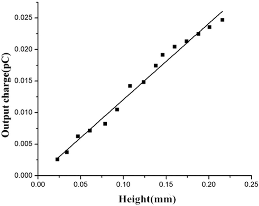
Relationship between SMPF electric charge and falling height of iron pellet.
Next, for each impact, height and position of the iron pellet were kept constant and γ value was changed. This caused maximum output charge of SMPF to vary. If γ value was changed by π/6 each time, charge response of SMPF exhibited variation as shown in Figure 9. In the impact process, displacement caused by the beam is a charge-flipping oscillatory displacement and SMPF also caused charge-flipping oscillating charge. Electric charge value shown in Figure 9 is the maximum positive electric charge value produced by SMPF in each impact process. It can be observed that the maximum output charge value of SMPF has a cosine relationship with the γ value.
Relationship between SMPF electric charge signal and included angle γ.
In another experiment to test sensing property of the simple harmonic vibration, one end of SMPF was fixed on the excitation head of the vibration exciter as shown in Figure 6(b). Displacement of the fixed end of SMPF was measured using a laser displacement sensor. Both generated output charge of the SMPF and displacement signals were measured (shown in Figure 10(a) and (b)). While maintaining the same impact amplitude and the same excitation frequency of 8.3 Hz, we changed the installation angle (γ) of the SMPF in the vibration experiment. Periodic signals of the SMPF in each vibration were intercepted and integrated into a picture. Figure10(c) exhibits that upon changing the angle, the generated output charges of SMPF change gradually. The peak value of the charge decreases from its maximum to zero and further to the negative maximum value.
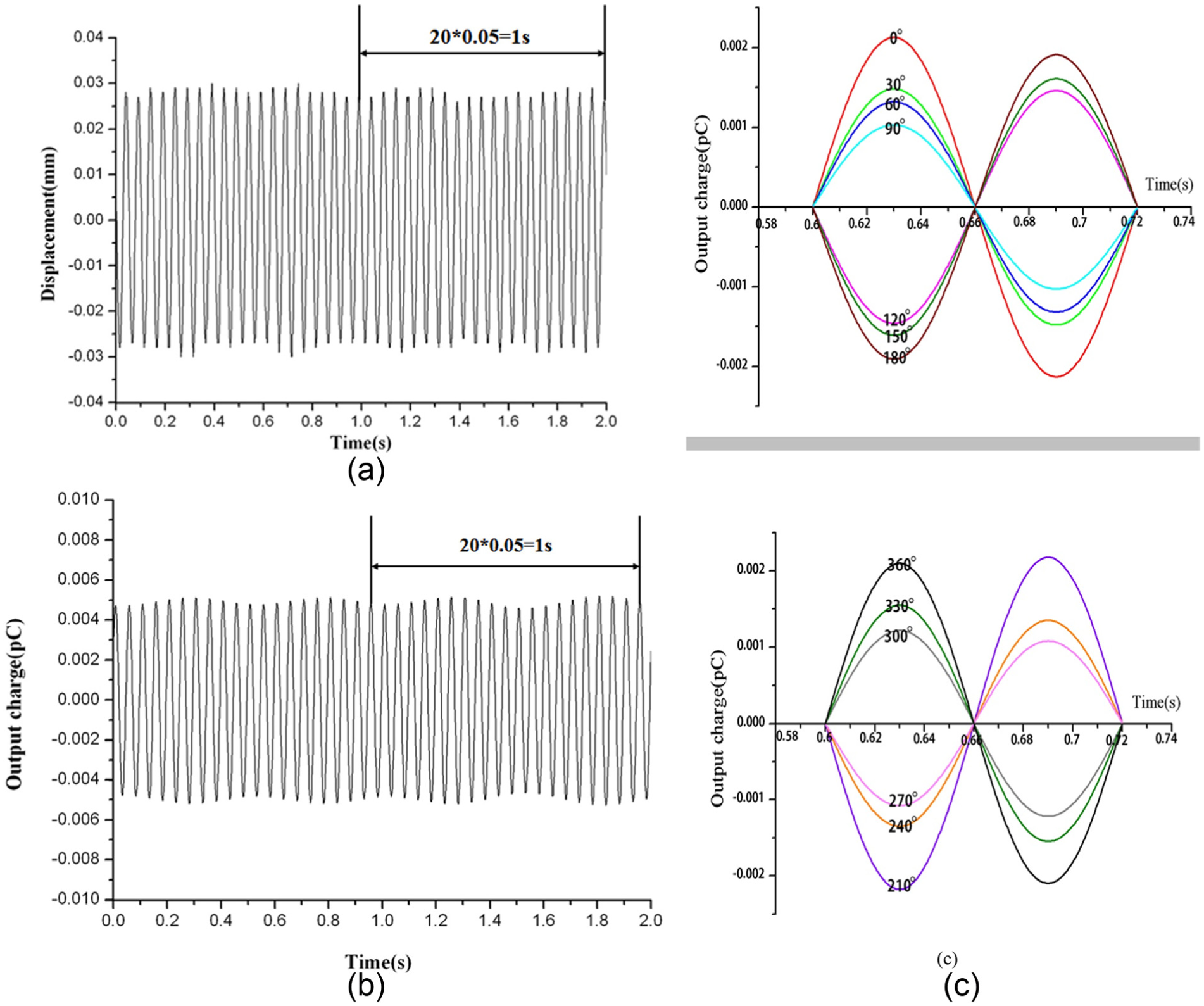
Electric charge signal of the SMPF simple harmonic vibration: (a) excitation head displacement, (b) electric charge signal of SMPF, and (c) electric charge signal of SMPF after rotation angle.
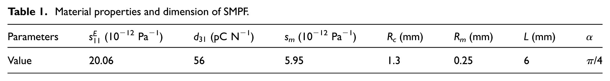
Displacement of the fixed end of SMPF is shown in Figure 10(a) and the response electric charge of SMPF is shown in Figure 10(b) for an excitation frequency of 20 Hz. It can be seen from the figure that when the fixed end undergoes a simple harmonic excitation, the response electric charge of SMPF is simple harmonic charge. In this case, both frequency and excitation frequency were the same. For an excitation frequency of 20 Hz, vibration amplitude of the exciter was changed. Amplitude of the SMPF output cosine charge signal is shown in Figure 11. Clearly, a linear relationship exists between the electric charge amplitude and excitation vibration amplitude. The sensitivity of this sensor is 0.127 pC mm−1. This verifies that electric charge Q in equation (14) has a linear relationship with excitation amplitude U0. The theoretical value was also calculated using equation (14), and the corresponding parameters are listed in Table 1. It can be seen that the experimental value is lower than the theoretical value, and this may be attributed to the low piezoelectric constant on the surface of piezoceramic. When a SMPF was polarized, the electric field intensity distribution was not uniform in the piezoceramic part due to the sector structure. The low electric field strength of the surface led to a lower piezoelectric constant.
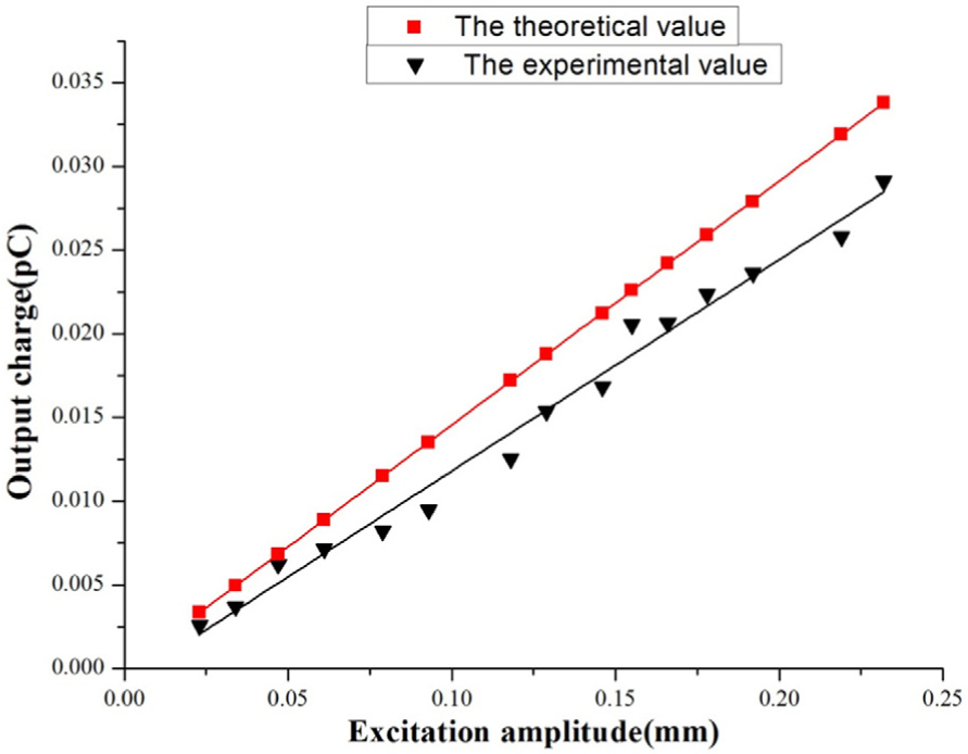
Electric charge amplitude of SMPF for different vibration amplitudes with a fixed vibration frequency of 20 Hz.
Material properties and dimension of SMPF.
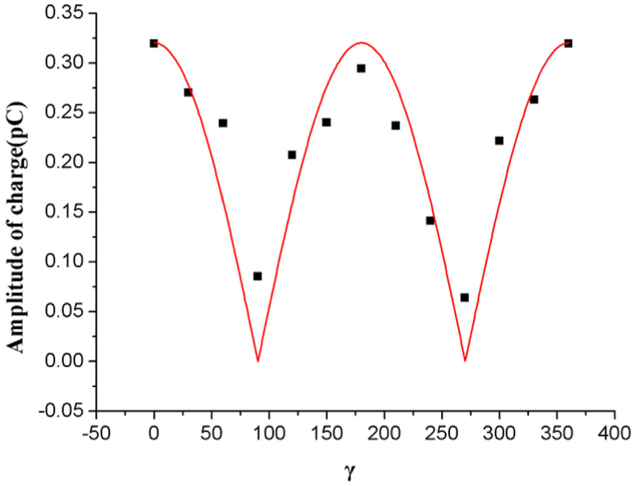
Next, excitation frequency was kept constant at 20 Hz, and amplitude of the vibration exciter was fixed. The γ angle value was changed and output charge amplitude of SMPF was measured, which is shown in Figure 12(a). It can be observed from equation (14) that the electric charge value Q and the angle γ are in cosine relationship with each other. Since electric charge value changes as a cosine curve, relationship between the electric charge Q and cosine absolute value of the angle γ can be obtained from equation (14). Figure 12 verifies this relationship. In the figure, the electric charge and the angle basically form the letter “W.” The relationship between angle and output signal is expressed using polar coordinates as shown in Figure 12(b). It reveals a figure of “8.” The impact angle experiment confirmed that the SMPF exhibited the ability to sense the direction of vibration.
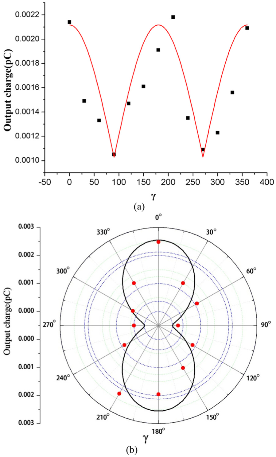
(a) Relationship between electric charge amplitude of SMPF and γ (Cartesian coordinate system) and (b) relationship between electric charge amplitude of SMPF and γ (polar coordinate system).
The experimental results show that the SMPF sensor can precisely measure the impact vibration and simple harmonic vibration of the matrix. When matrix materials undergo impact vibration, SMPF response electric charge reflects amplitude of the impact and time response. Moreover, the SMPF can sense direction of the impact vibration. When matrix materials undergo simple harmonic excitation, the SMPF allows accurate measurement of the excitation frequency and amplitude along with excitation direction. If errors in fabrication of the SMPF, such as position of the metal core, size of the surface electrode and locations, uneven distribution of the electric field, can be ignored, the experimental observation is consistent with the trend predicted by the theoretical model.
Conclusion
In this study, design and fabrication of vibration sensors based on the hair sensors of insects similar to the water strider, which has the ability to sense fluctuation on the water surface, was proposed. Platinum core piezoelectric ceramic fiber body was prepared by squeeze and press method. A cantilever beam structure with two surface electrodes was used as the sensor in the theoretical model. Experiments were performed to verify sensing property of the sensor under impact vibration and simple harmonic excitation. Result showed that the SMPF could sense impact vibration amplitude and direction along with frequency, amplitude, and direction under simple harmonic excitation. Such an artificial biomimetic fiber has wide application prospects due to its impact vibration and mechanical vibration sensing properties.
Footnotes
Declaration of conflicting Interests
The author(s) declared no potential conflicts of interest with respect to the research, authorship, and/or publication of this article.
Funding
The author(s) disclosed receipt of the following financial support for the research, authorship, and/or publication of this article: This research was supported by the National Natural Science Foundation of China (Grant No. 51275447 and 51775483) and Yangzhou city–Yangzhou University Cooperation Project (Grant No. 2014-11).