
Abstract
This study investigates a newly developed positioning system based on a rotary magnetorheological damper with power generation capability, comprising an electromagnetic power generator (energy extractor) generating electrical power, an magnetorheological damper which alters the damping characteristics of the system and an electrical interface, connected in between the coil of the generator and the damper control coil, which conditions the voltage output from the generator. Structural configurations of the damper and the generator are outlined, and the results of their testing and the testing done on the entire system are summarised, covering the tests conducted with and without the interface, under the idle run and under load in the assumed velocity range. The objective of the work is to examine the performance of the proposed positioning system through experiments. Results of the system testing in the uncontrolled case (passive system) and in the controlled one (semi-active system) in a purpose-built test rig are compared and discussed. Three design options of the electrical system controlling the damper are explored. In the first option, the damper is assumed to be controlled starting from the initial moment of the motor shaft’s motion, and in the second option, the control action begins at the instant when the motor shaft assumes the present position. The third variant is similar to the first one except that an additional condenser is connected behind the Graetz bridge. The results confirm the adequacy of the developed positioning system and demonstrate an improvement in control of the system’s dynamic behaviour.
Introduction
Positioning systems have received a great deal of researchers’ attention. These systems are implemented to control tool movements (during drilling, milling, cutting, boring operations) or point-to-point motion of the entire machines (such as robot welding tool). They are also incorporated in various pick-place machines (Yihuan et al., 2011). In position control systems, the main objective is to minimise the time required for reaching the predetermined position and the same eliminating the vibration of an object whose position is to be controlled. That the object oscillates around the preset position can be attributed to insufficiently rigid connections between the driving components and the object itself and to clearances or friction in mechanical components. Variable load is a major determinant of the positioning system’s performance, which is of particular importance in drilling machines.
One of the strategies adopted to eliminate these undesirable phenomena involves the modification of the controller’s structural design and of algorithms for control of the component inducing the object’s motion (an electric motor in most cases). For example, Wahyudi and Albagul (2005) and Mohd and Aminudin (2011) demonstrated that when a nominal characteristic trajectory following controller is incorporated in the system for controlling the position of a 2 degree-of-freedom (DOF) object, and tuned accordingly in the open-loop system, the overshoot and control time are significantly reduced. To reduce the object’s vibrations around the target position, Verscheure et al. (2006) suggested that a regulator H∞ be incorporated in the position control system, thus reducing the time and amplitude of the object’s oscillations. Such solutions can be effective as long as the algorithm of motor control can be varied at any moment. It is often so, however, that modification of the control algorithm is not feasible. In such case, adaptive control systems are good solutions because the controller settings are adjusted by on-line identification when the system is operated. Alongside conventional controllers and feedback loops, adaptive control systems are equipped with filters allowing the unit’s resonance frequencies to be detected. These filters are usually installed ahead of the torque controller which uses the signal of current taken up by the motor (variations of the current level correspond to variations of the motor loading moment). Adequacy of such solutions was confirmed in works by Bong and Chung (2002) and Miyazaki and Ozaki (2005).
Vibrations of the object to be position-controlled can be reduced by incorporating actuators (dampers) based on smart materials, such as piezoelectric materials or magnetorheological (MR)/electrorheological (ER) fluids. Applications of MR/ER actuators in vibration control systems were explored in works of Sun and Thomas (2011), Weber et al. (2013), Gołdasz and Dzierżek (2016), Rosół and Martynowicz (2016), Abdeljaber et al. (2016), Sun et al. (2016) and Naito et al. (2009).
As regards MR dampers in such applications, Jolly (1999) revealed that a liner damper supporting a pneumatic cylinder led to reduction of the object’s oscillation around the preset position. Yadmellat et al. (2014) and Fernández and Chang (2016) suggested that the robot arm control system should incorporate a cylindrical MR clutch with permanent magnets. Thus, the robot grip can be safely manoeuvred into its target position using just one direct current (DC) motor. Yang et al. (2012) showed that providing MR dampers in manipulator joints led to reduction of the jitters effect during the positioning of the robot arm.
Bai et al. (2011) demonstrated the application of an MR damper in the motor speed control system. Another most undesirable phenomena frequently occurring in rotating machinery and impairing the position control are torsional vibrations and vibrations occurring at critical speeds. Test results showed that damping torque control of a rotary damper leads to reduction of torsional vibration amplitudes (Pręgowska et al., 2013) and of vibrations at critical speed (Wang and Meng, 2005). Rotary MR dampers are widely used in manipulators to improve the accuracy of position control and to reduce vibration. Altering the variable viscosity coefficient and variable impedance control through MR damper control leads to improvement of dynamic properties of an artificial muscle manipulator (Nagai et al., 2011; Tomori et al., 2013). Shin et al. (2013) demonstrated that incorporating a rotary MR damper in a pneumatic manipulator interacting with a DC motor results in improvement of the manipulator’s operation precision and efficiency.
Other noteworthy actuators that can be used in such applications are MR dampers which do not require an external power source and can be controlled using energy harvested from vibrations (Cho et al., 2007; Li et al., 2013; Sapinski, 2011, 2014; Snamina and Sapinski, 2011; Wang and Wang, 2010). Moreover, some newly developed MR dampers have also self-sensing capability as for example that is proposed in the work of Hu et al. (2017).
The position control system proposed in this study incorporates a rotary MR damper power supplied with energy harvested from vibrations through the use of an electromagnetic generator. Key components of the position control system include an alternating current (AC) motor, a rotary MR damper and a power generator. The motor, connected to the controlled object via an elastic element (elastic shaft), acts upon the object to be positioned to move it to the target position. As soon as the shaft covers a specified distance, it stops. Once the movements of the motor shaft cease, the object will for some time oscillate around the preset position. To improve the dynamic features of the system, new elements are incorporated: an MR damper, a generator and a conditioning system connected between the damper coil and that in the generator. Thus, the object’s position can be controlled through altering the anti-torque in the MR damper using the energy harvested from the object’s vibration.
This work is organised as follows. Sections ‘MR damper’ and ‘Generator’ summarise the design structure of the MR damper and the power generator and provide the experimental characteristics. Section ‘MR damper–generator system’ investigates the MR damper–generator system by way of experimental testing. Section ‘Test rig’ focuses on the test rig and the measurement and control equipment used in the experiments. Tests results of a proposed MR damper–based positioning system are discussed in section ‘Experimental tests’, demonstrating its adequacy and improvement of control of the system’s dynamics. Final conclusions are given in section ‘Summary’.
MR damper
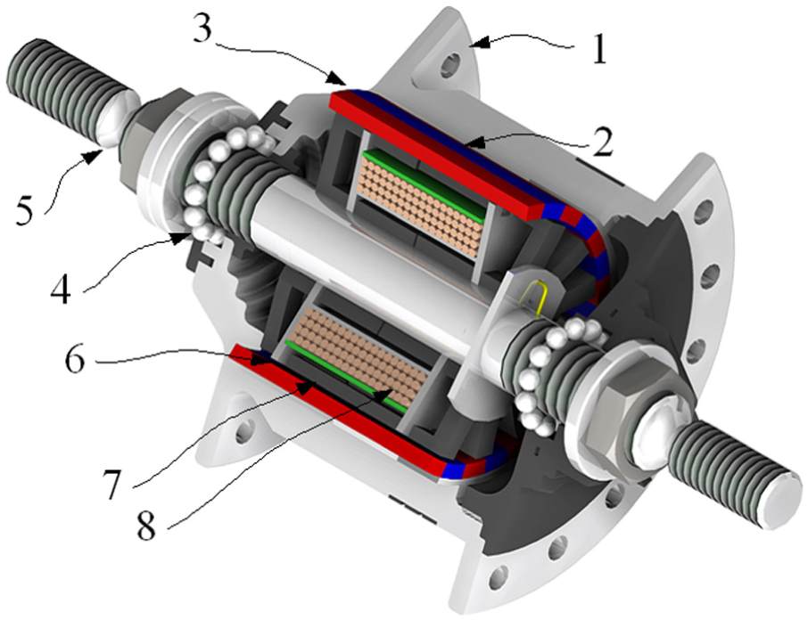
The damper assembly is depicted in Figure 1. The damper comprises a double-ended shaft (1) made of non-magnetic steel, mounted in a sectional housing (2) on rolling bearings. The housing (2) is made of magnetic steel. On the shaft there are four discs (4) moving between three immobile discs (5) mounted in the damper housing. Both moving and immobile discs are made of magnetic steel, and the space between the discs is filled with a MR fluid. Rubber seals (6) protect the system from fluid leakage. Discs and MR fluid are inside the carcass (7) of the control coil (8) having 306 turns of windings of wire 0.04 mm in diameter. Inductance of the control coil Ld = 0.810 H, resistance Rd = 15.32 Ω. Figure 2 shows geometry of the damper, whereas dimensions of its major components are summarised in Table 1.
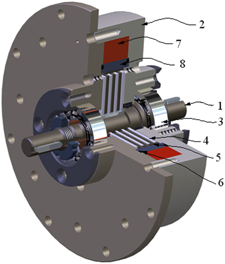
Damper assembly cut-out view.
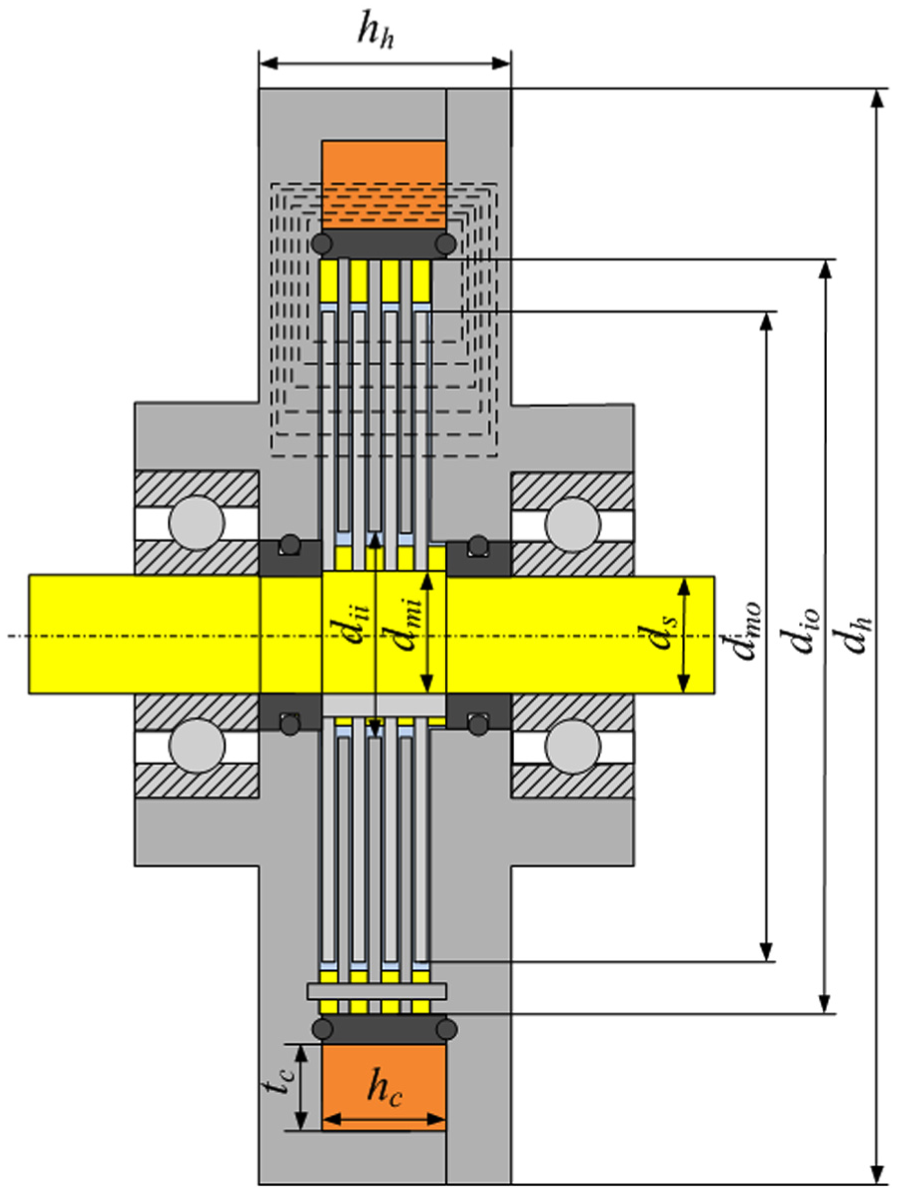
Geometry of the damper.
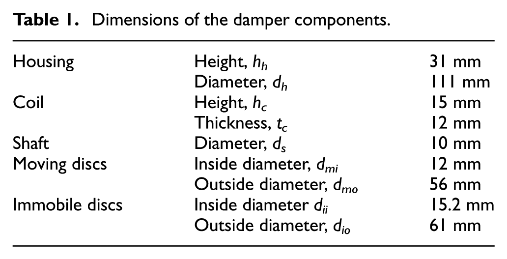
Dimensions of the damper components.
In Figures 3 to 6, we present selected characteristics of the damper which were obtained under the sinusoidally varying input φ = Asin(2πft) and for constant current levels I in the control coil: 0, 0.1, 0.2, 0.3, 0.4 A. The amplitude of the applied input was A = 0.36 rad, and its frequency fell in the range (1, 12) Hz with step of 1 Hz. Figure 3 illustrates the dependence of damping torque on displacement Td(φ), and Figure 4 shows plots of the damping torque versus velocity Td(ω) relationship for frequencies 1 and 10 Hz. Figures 5 and 6 plot the relationships rms damping torque Td and between rms energy dissipated by the damper Edh and rms velocity and current.
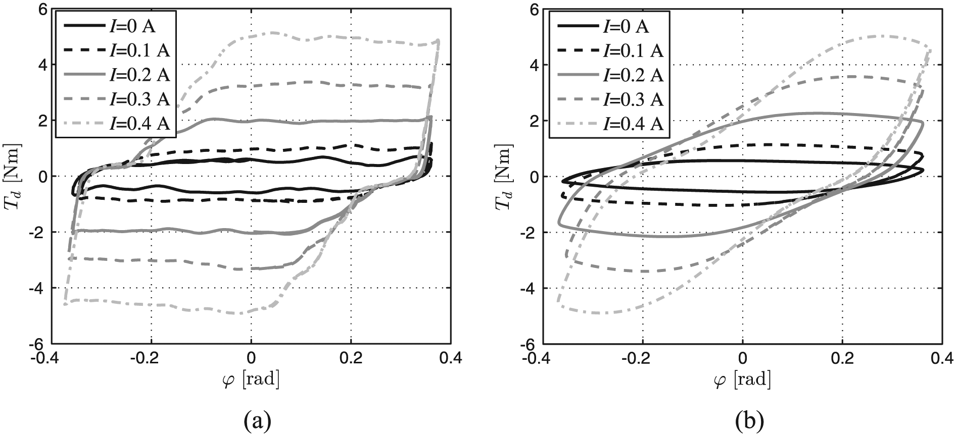
Torque Td versus position φ: (a) 1 Hz and (b) 10 Hz.
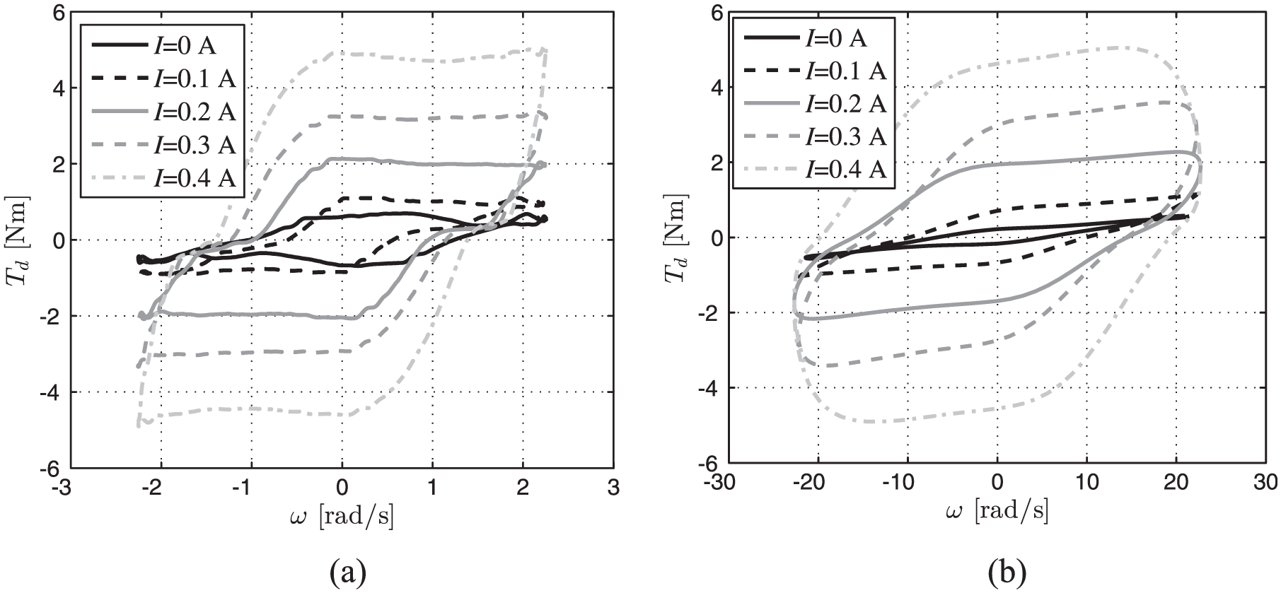
Torque Td versus velocity ω: (a) 1 Hz and (b) 10 Hz.
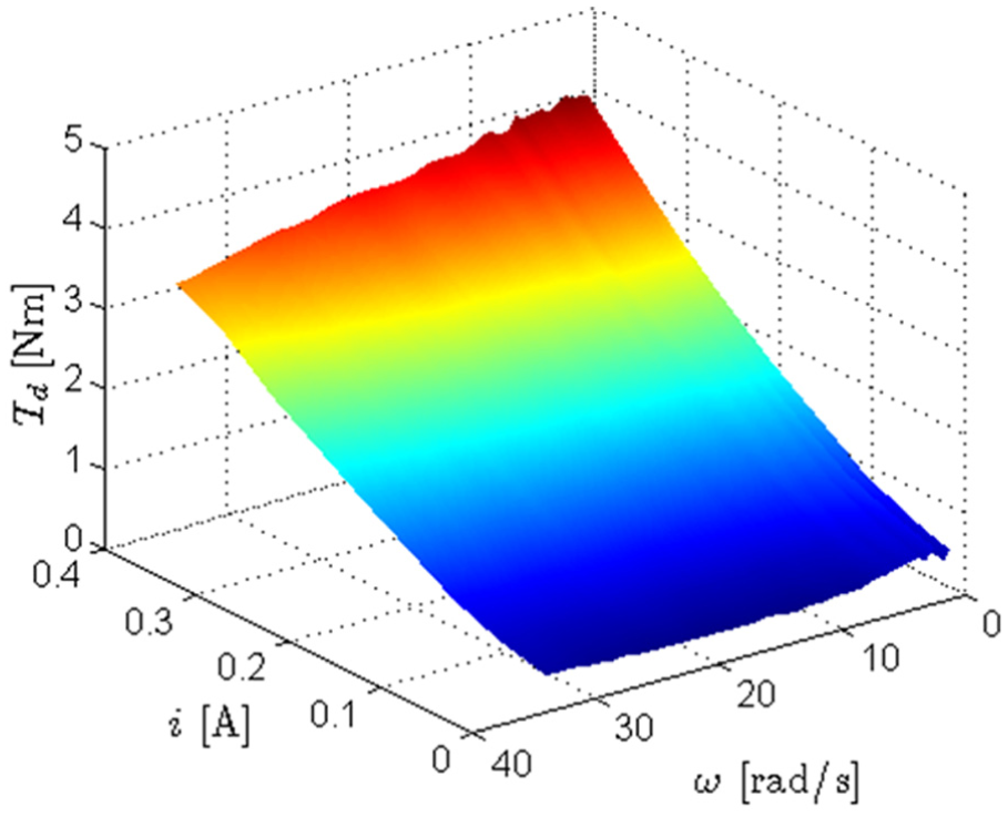
rms values of torque Td versus rms values of velocity ω and current i.
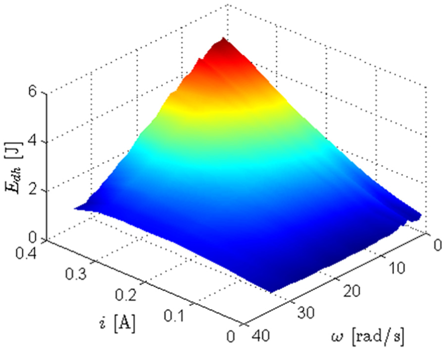
rms values of dissipated energy Edh versus rms values of velocity ω and current i.
Apparently, Td(φ) and Td(ω) plots reveal a hysteresis. The damping torque value tends to increase with increasing current level (for I = 0 A, Td = 0.5 N m, for I = 0.4 A, Td = 5 N m). The actual pattern of Td(φ) and Td(ω) plots changes with increasing frequency, which is manifested by reduction of energy dissipated by the damper and the maximal rms Edh = 4.75 J.
Generator
The structure of the generator is shown in Figure 7. A cylindrical rotor (1) is made of non-magnetic material and embedded on its inside wall is a thin-walled cylinder (2) made of ferromagnetic metal plate with 28 permanent magnets (3) uniformly distributed over its circumference. The magnets are configured into 14 pairs of magnetic poles. The rotor is mounted on ball bearings (4) and set on the shaft (5) to which the stator (6) is attached. The stator comprises 14 pairs of rectangular frames (7) (to match the number of pairs of magnetic poles), made of ferromagnetic steel plates. Frames are arranged radially on the shaft and attached to the carcass made of an electro-insulating material. Each frame consists of two half-sections connected inside the coil (8) and shaped such that each half-section corresponds to one magnetic pole (the frames being shifted with respect to one another by about 13°). Inside the frames there is a coil (306 turns of windings of wire 0.2 mm in diameter), wound upon the carcass in the direction normal to the frames. Inductance of the generator coil is Lg = 0.031 H and its resistance Rg = 2.7 Ω. The coil core is made from frame sections inside the coil being in contact with the shaft.
Generator assembly cut-out view.
Selected characteristics of the generator obtained under the idle run are shown in Figures 8 and 9; those obtained under load (the load being the control coil in the MR damper) are given in Figures 10 and 11. Figure 8 plots the emf e versus relative time for various values of rotational velocity, and the relationship between the rms value of electromotive force and velocity ω is shown in Figure 9. For rotational velocity ω = 6.28 rad/s, the emf frequency is about 14 Hz (which is the consequence of 14 pairs of magnetic poles), and the value of rms e increases linearly with increasing ω (przy ω = 50 rad/s; e = 48.54 V). Figure 10 plots the voltage u and current i versus time, for ω = 31.42 rad/s, and the dependence between rms u and rms i on velocity ω is illustrated in Figure 11, revealing a phase shift between the voltage and current plots approaching 50.35°. The values of rms u and i tend to increase with increasing velocity (for ω = 50 rad/s rms u = 37.95 V, rms i = 0.27 A).
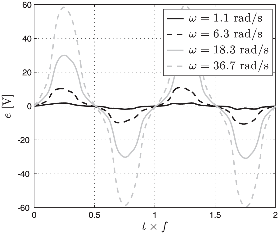
Time history of emf e.
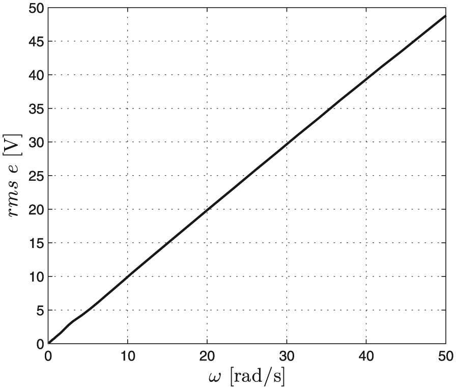
rms values of emf e versus velocity ω.
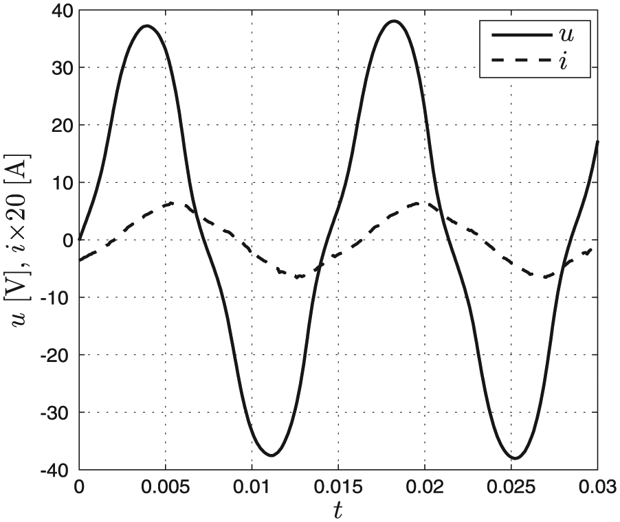
Time histories of voltage u and current i.
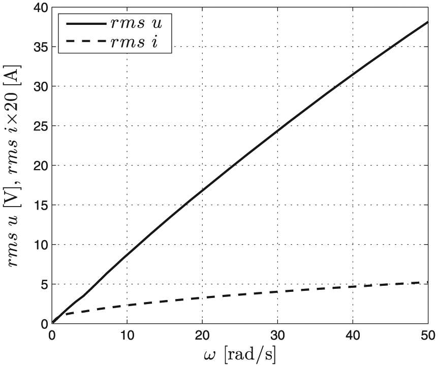
rms values of voltage u and current i versus velocity ω.
MR damper–generator system
The next stage testing was done on the MR damper and generator system mounted on a joint shaft having high stiffness. The following system configurations were considered: when the damper coil and the generator coil were not connected (NS), when the damper coil was directly connected to the generator coil (DS) and when the damper coil was connected to a generator coil via a Graetz bridge (GS). Tests were conducted in two stages. In the first stage, the input was applied with the time constant velocity (ω = const) which varied in the range (0.1, 50) rad/s. The damping torque Tdg dependence on velocity ω in the steady state conditions is illustrated in Figure 12, revealing that at the same rotational velocity, the damping torque value in the case DS would slightly increase in relation to NS. For ω = 50 rad/s, this increase is the most significant, approaching 0.22 N m. In the configuration GS, the rms value of Tdg increased (for ω = 50 rad/s rms Tdg = 2.9 N m) when compared to NS and DS. In the second stage, harmonic input was applied φ = Asin(2πft) with the amplitude A = 0.36 rad and frequency f varying in the range (1, 15) Hz, and again the cases NS, DS and GS were considered. Figure 13 shows the damping torque versus displacement plot Tdg(φ) while the relationship between the damping torque and velocity Tdg(ω) at 1 and 10 Hz is shown in Figure 14. Figures 15 and 16 plot the energy supplied to the control coil in the damper Egd and energy dissipated in the damper Edh. It appears that at frequency 1 Hz, the values of damping torque Tdg are similar in each of the three cases: NS, DS, GS. Apparently, the presence of the Graetz bridge in the GS configuration is the major determinant of the actual Tdg level. Both Egd and Ehd tend to increase with increasing velocity. At ω = 23.4 rad/s, energy dissipated in the damper reaches the value Egd = 0.24 J, which accounts for 5.9% of Edh.
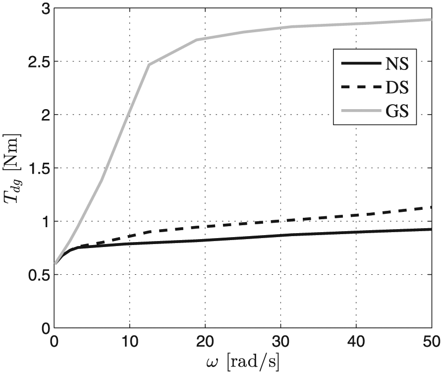
rms value of torque Tdg versus velocity ω.
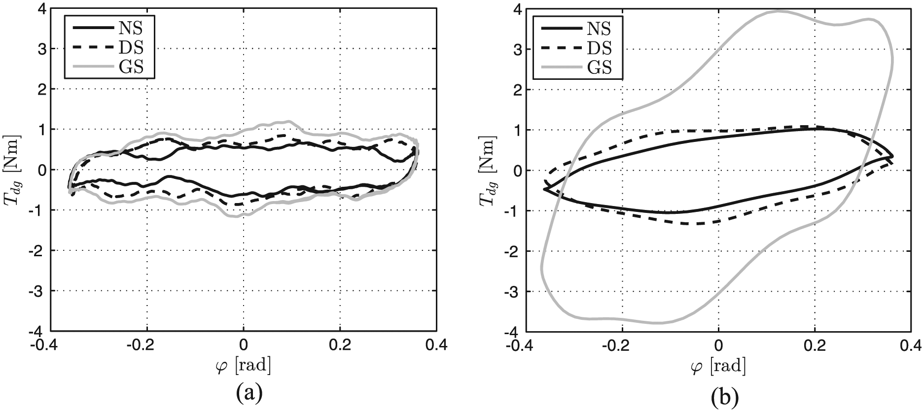
Torque Tdg versus position φ: (a) 1 Hz and (b) 10 Hz.
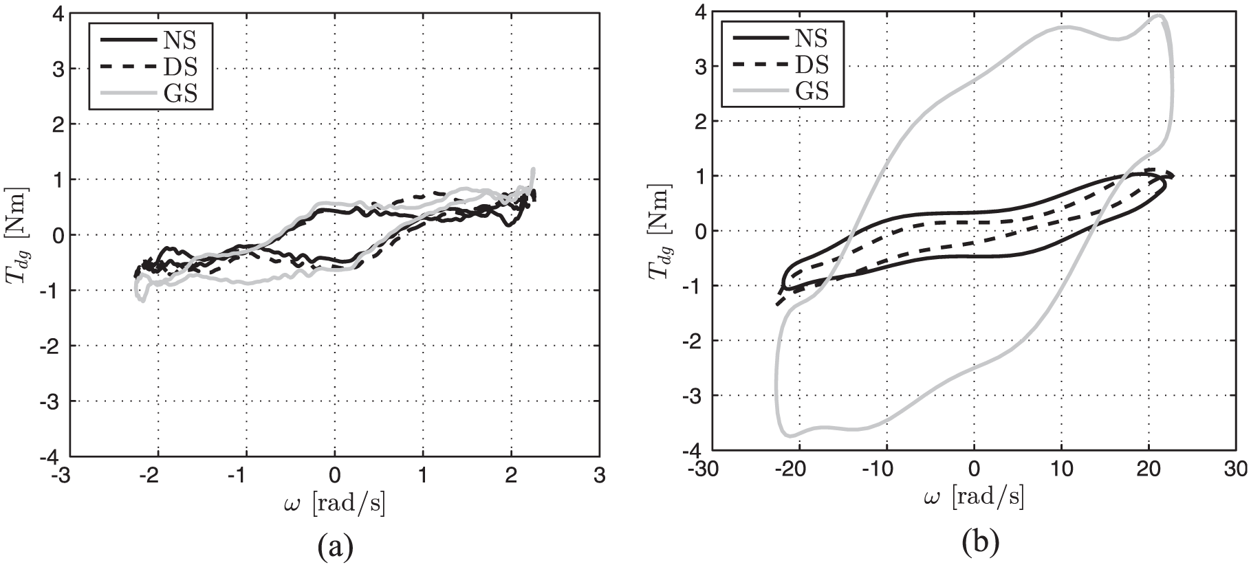
Torque Tdg versus velocity ω: (a) 1 Hz and (b) 10 Hz.
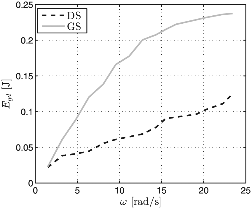
Energy provided to the control coil Egd versus velocity ω.
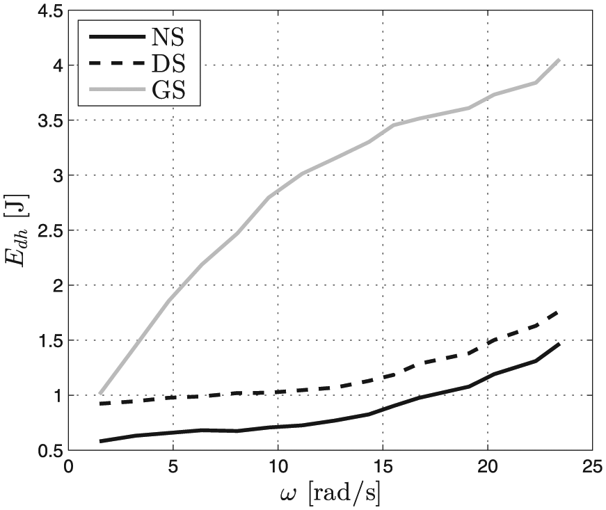
Energy dissipated Edh versus velocity ω.
The scheme of the considered positioning system incorporating an MR damper and a generator is shown in Figure 17. The equation of motion can be written as
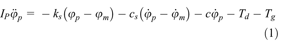
where Td is damping torque in the damper, Tg is damping torque in the generator, Ip is mass moment of inertia of an object to be positioned, cs is material damping and c is equivalent damping ratio of the remaining elements of the system.
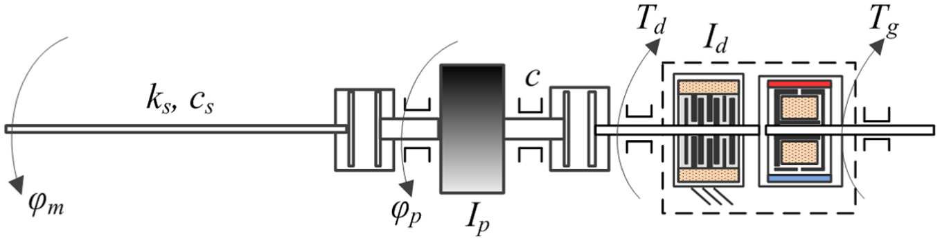
Scheme of the positioning system.
It is apparent that damping torques Td and Tg counteract the object’s motions (energy dissipation). The input to the system is the angular displacement φm, and the output parameter is angular displacement φp of the object whose position is controlled. The system considered in this study has the following elements: a source of mechanical energy (an electric motor), a potential energy accumulator (elastic shaft), an accumulator of kinetic energy (the object to be positioned), an energy-dissipating element (MR damper) and a device that converts kinetic energy of the object being positioned into electric power (generator).
Test rig
The main components of the experimental setup include a synchronous motor interacting with a controller, the object to be positioned, an MR damper and a generator. A general view of the test rig is shown in Figure 18. Inside the motor housing (on the shaft) there is an encoder 1. The object whose position is controlled is connected to the motor via an elastic shaft. The object’s displacement is measured with the encoder having the resolution of 1024 impulses per rotation. An MR damper and a generator are connected to the object via a clutch. The mass moment of inertia of the positioned object equals Ip = 25 × 10−4 kg m2. Elasticity modulus of the shaft is ks = 15.66 N m/rad. The mass moment of inertia Ip of the elastic shaft is neglected as it is rather small in relation to that of the controlled object. The resultant mass moment of inertia of other components in the setup (clutches, discs in the MR damper, discs in the encoder 2) is equal to Id = 6 × 10⁻⁴ kg m2. Sub-assemblies giving rise to Id are fitted between the motor and the MR damper and connected with one another by rigid elements.
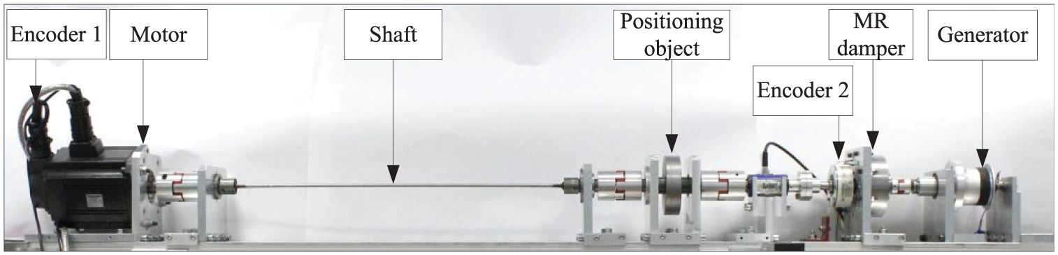
Positioning system – general view.
The measurement and control module (see Figure 19) being a part of the positioning system comprises a motor control block, a purpose-built energy management block used for data acquisition and control of the MR damper. The synchronous motor operates in the step/direction mode with position and torque controllers implemented inside the drive system being in the ‘on’ position. The input to the motor control block is position φset. The motor is operated in the open-loop control system wherein the number of impulses corresponds to the shaft’s angular path, and their frequency corresponds to angular velocity. The number of impulses per one rotation is 1024. The motor control program, developed in LabVIEW, generates two impulse sequences using the I/O board. The first sequence determines the modulus absolute value for the subsequent step (0 or 1), the other determines the direction. The impulses are fed to the controller/drive input. Using the cascade of position and torque regulators, it controls the motor such that the preset position φset should be implemented.
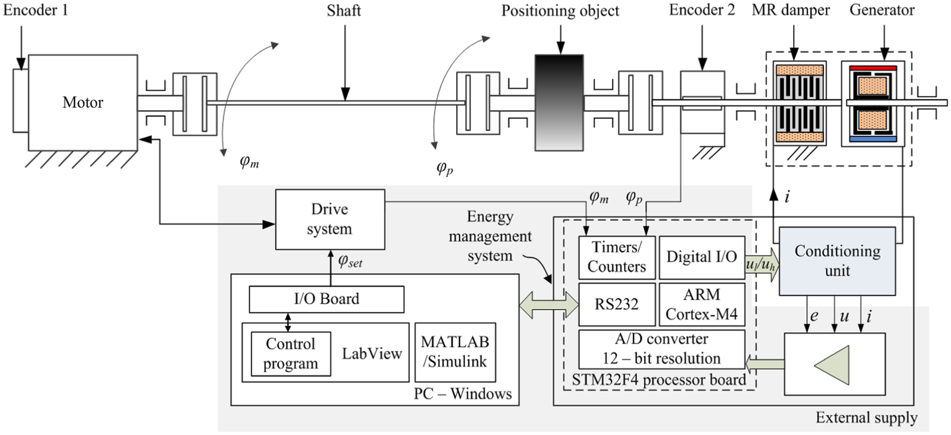
Diagram of the measurement and control module.
The energy management block incorporates two integrated parts: a conditioning unit and a measurement and control unit complete with an electronic analogue signal conditioning system and a STM32F4 processor board. The measurement block uses high-precision instrumentation amplifiers. The STM32F4 (STM Microelectronics, 2013) processor boards is based on a 32-bit processor ARM Cortex-M4 (a float point operation unit). The control unit incorporates an analogue-to-digital (A/D) converter to measure analogue quantities from the energy-conditioning system. Instantaneous positions (the distances covered by the motor shaft φm and by the object φp) are measured with the time–counter systems converting the sequences of impulses from encoders into instantaneous values of the angular positions, with the movement direction detection functionality. Detection of the movement direction is necessary when the positioned object tends to oscillate. Relays K are controlled using pulse width modulation (PWM) signals. Communication between PC and the STM32F4 processor board is effected via a serial port universal asynchronous receiver/transmitter (UART). Because of engineering constraints and the value of induced voltage in the generator operated under the idle run, the value of velocity considered in the tests was 21 rad/s. The sampling frequency in signal measurements was 0.5 Hz.
Experimental tests
The performance of the positioning system was tested in two operation modes: the passive mode – absence of control (NE – when the damper is not powered, DG – when a Graetz bridge is provided in between the damper coil and the generator coil) and in the semi-active mode (the damper control in accordance with the selected control algorithm). In both cases, the set value of angular position was φset = 6.28 rad.
Figure 20 shows the diagram of the system operated in the semi-active mode. The value of current ic derived by the control algorithm is compared to the instantaneous current level i in the circuit, measured via a voltage drop on resistor RS(Texas Instruments, 2015). The resultant control error εi determines whether the relay K is on or off. The relay switches on when voltage u1 = 0 V is applied to its control terminal, and it is off when voltage becomes uh = 3.3 V. Since the system is capable of handling voltages up to 100 V (it is reasonable to anticipate high instantaneous voltage levels associated with inductance at the instant when the current suddenly ceases in the circuit), the system AQV255 (Panasonic Industrial Devices, 2017) will act as the relay. A diode D0 is provided to implement quick discharge of energy accumulated in the coil.
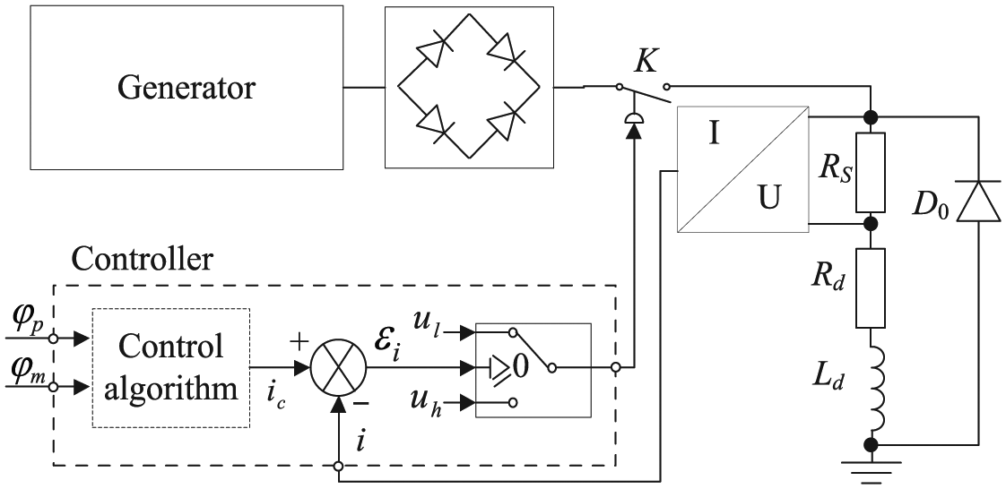
Diagram of the energy management block.
The conceptual design of the positioning system is shown in Figure 21. Energy recovered from the object’s oscillations while it is positioned is converted in the conditioning system and then utilised to power (control) the MR damper.
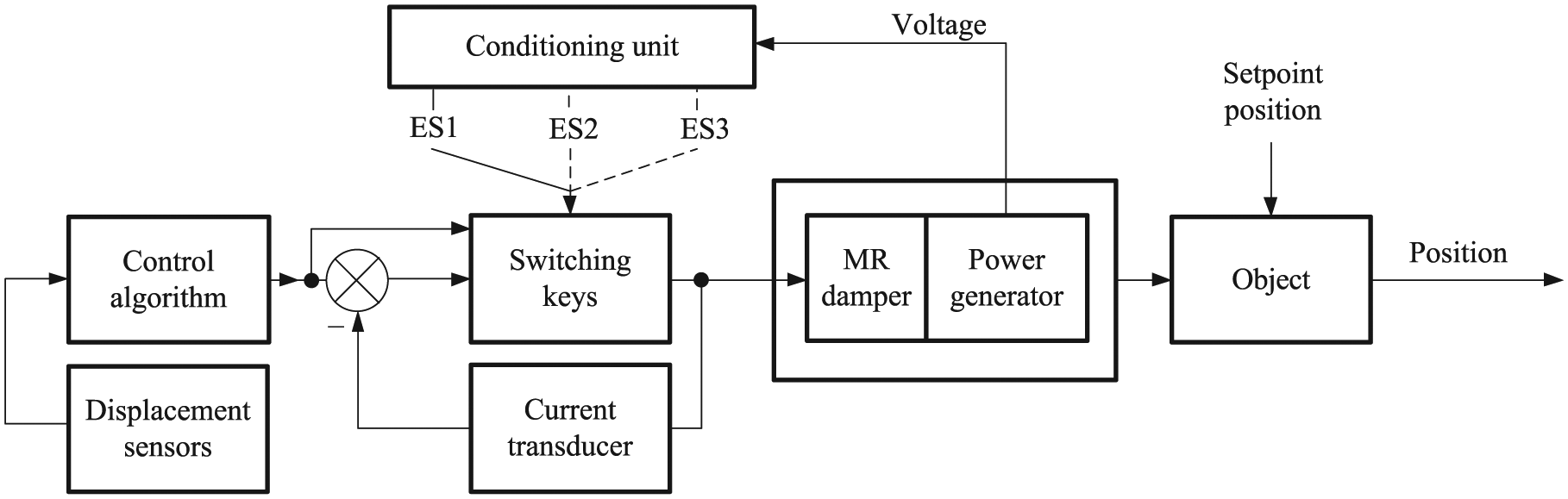
Diagram of the positioning system.
Figure 22 illustrates three configurations of the conditioning system (ES1, ES2, ES3) during the positioning system testing. In the case of ES1 configuration, it is assumed that the damper control begins from initial moment of the motor shaft’s movement. In the case of ES2, the control is assumed to be switched on at the instant when the shaft assumed its preset position (φm = φset). In the ES3 configuration, a condenser is provided behind the Graetz bridge, and damper control begins at the initial moment of the movement (unlike the ES1 structure).
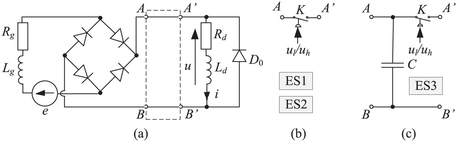
Structures of the conditioning unit: (a) ES1, (b) ES2 and (c) ES3.
To determine how the presence of a damper and a generator should affect the accuracy of position control, the plots of position φp versus time were obtained for the following cases (see Figure 23):
The damper and generator are absent, not connected to the object (Case M);
The damper is connected to the object, yet it is not powered (Case TO);
The damper and generator are present though their coils are not inter-connected (Case NE).
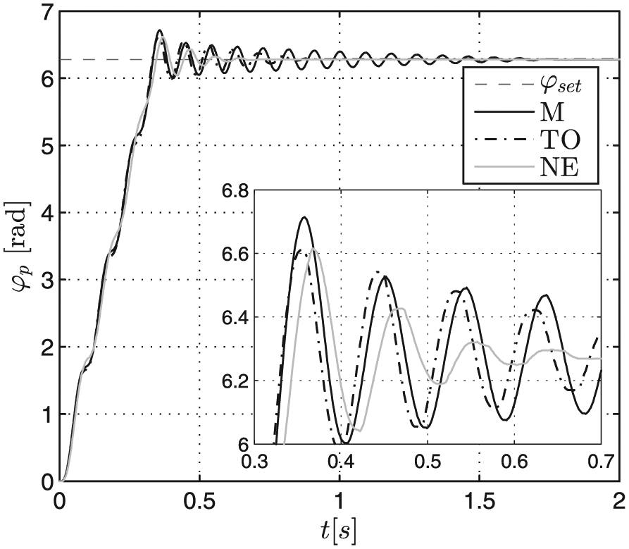
Time history of the object position φp.
Evaluation and comparison of the positioning system’s performance rely on two indicators: time tu, after which the object’s vibration should not exceed ±1% of the preset position φset (starting from the initial moment of the movement) and the absolute overshoot φpmax. Plots in Figure 23 indicate that the time tu and overshoot φpmax become 1.33 s, 0.434 rad (Case M); 0.72 s, 0.331 rad (Case TO); and 0.52 s, 0.335 rad (Case NE). Damping provided by connecting a damper and a generator (Case NE) led to the reduction of the time tu by 60.9% and overshoot φpmax by 22.8% in relation to the case M. The position φp(t) obtained in the case NE will be henceforth considered as the reference level.
Passive mode
Two cases of passive mode of operation were considered: NE and DG. As regards the case DG, three structural configurations, ES1, ES2 and ES3, of the conditioning unit were considered (see Figure 23). In the configurations ES1 and ES3, the relay K remains off from the initial moment of the movement; in the case ES2, the relay is off when φp = φset. Figure 24 plots the object’s displacement in the case NE and DG and alsothe object’s ωp and current i.
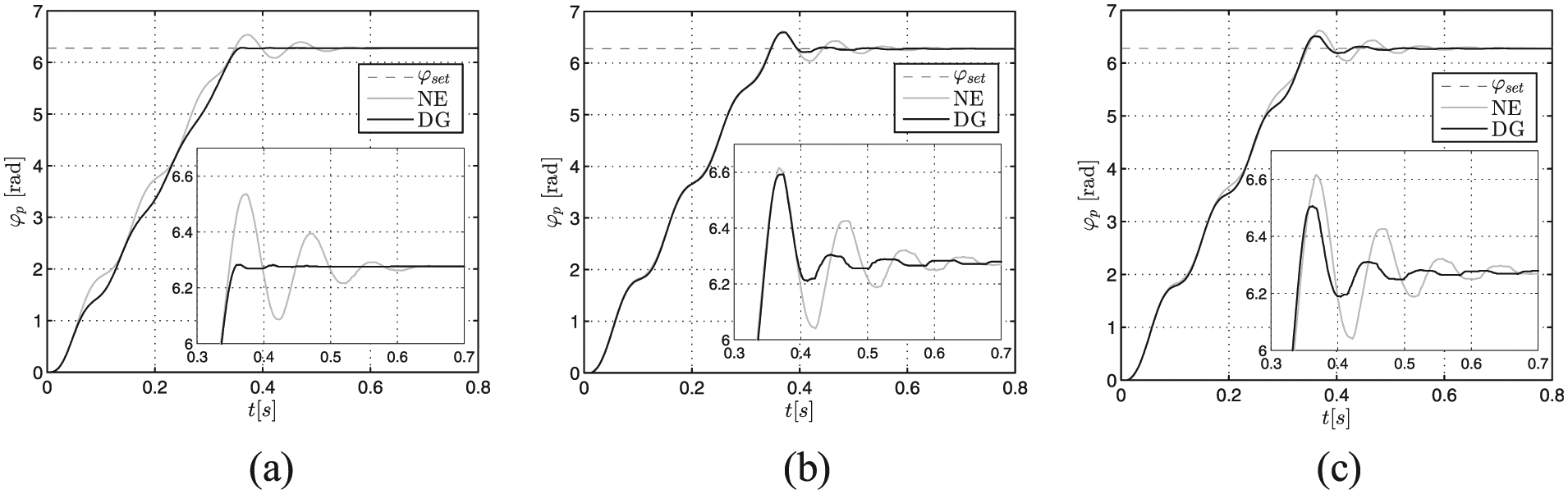
Time histories of the object position φp: (a) ES1, (b) ES2 and (c) ES3.
The shortest time tu and the smallest overshoot φpmax is obtained for ES1 (Table 2). It appears (see Figure 25) that for ES1, the current level in the circuit remains constant (about 0.5 A) for nearly the whole time when the object reaches its preset position. In the case ES1, the MR damper adds the torque, and its operation is desirable only at instants when the object’s energy ought to be dissipated. In the remaining time, it provides additional damping torque to the motor, which is undesirable.
Values of tu and φpmax; case DG.
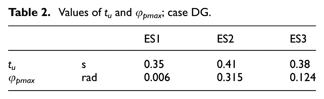
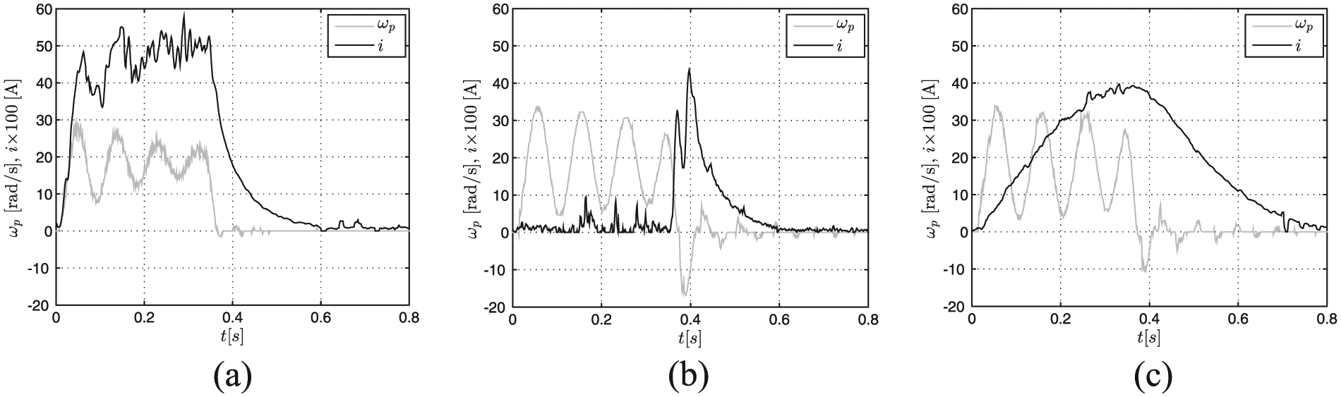
Time histories of the velocity ωp and current i: (a) ES1, (b) ES2 and (c) ES3.
Semi-active mode
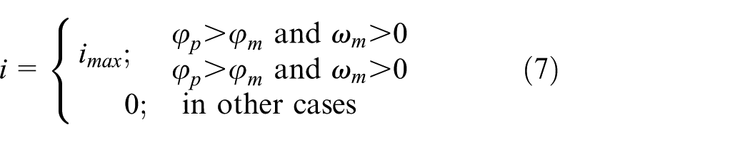
Following a thorough analysis of φm(t) and φp(t) and their derivatives, the analogue and discrete versions of the damper control algorithm were suggested. Continuous control algorithms (CA1, CA2) rely on the relay K implementing the present patterns of current i, assuming that the value i should fall in the predetermined range (0, 0.6) A. The maximal current level imax was derived from the experimental test data of the generator, the load being the damper coil. Discrete algorithms (DA1, DA2) determine the time instants in which the value of current i becomes either 0 or 0.6 A. The algorithm CA1 operates such that the damper is switched on at instants when the absolute value of the object’s velocity
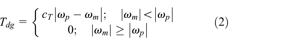
To obtain the required level of damping torque Tdg, the value of current i (for CA1) should be governed by the equation
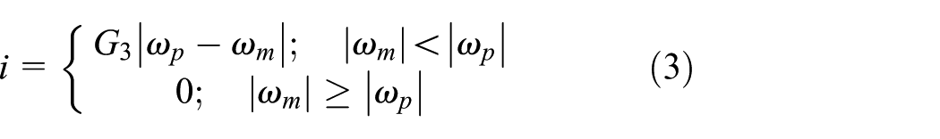
where G3 is a coefficient having a fixed value 0.006 A s/rad.
The algorithm DA1 is governed by the equation

The underlying assumption in algorithm CA2 relying on positions φm, φp and velocities ωm, ωp obtained accordingly is that the damper ought to be switched on exclusively when the object’s position increases its value in relation to that of the motor shaft position φm. At time instants when
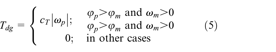
In order to implement the torque determined by CA2, the current in the control coil should be governed by the equation
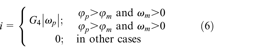
where G4 is a coefficient having a fixed value 0.006 A s/rad.
The algorithm DA2 is expressed by the equation
The values of coefficients G3 and G4 were chosen experimentally. In the first step, the research examines the semi-active mode of operation of the position control system for ES1. Figure 26 shows time histories of the angular position φp for all control algorithms.
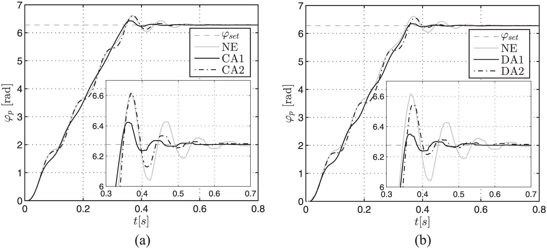
Time histories of the object position φp: (a) continuous control and (b) discrete control; ES1.
Table 3 compiles the values of tu and φpmax, read out from plots in Figure 26. It appears that the lowest values of tu and φpmax were obtained in the case DA1.
Values of tu and φpmax; structure ES1.
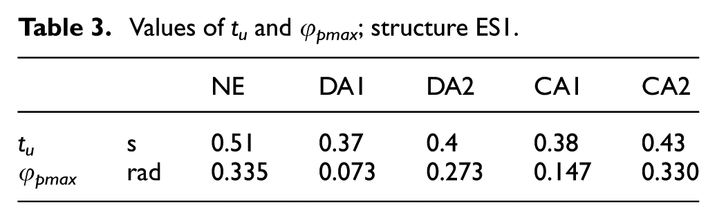
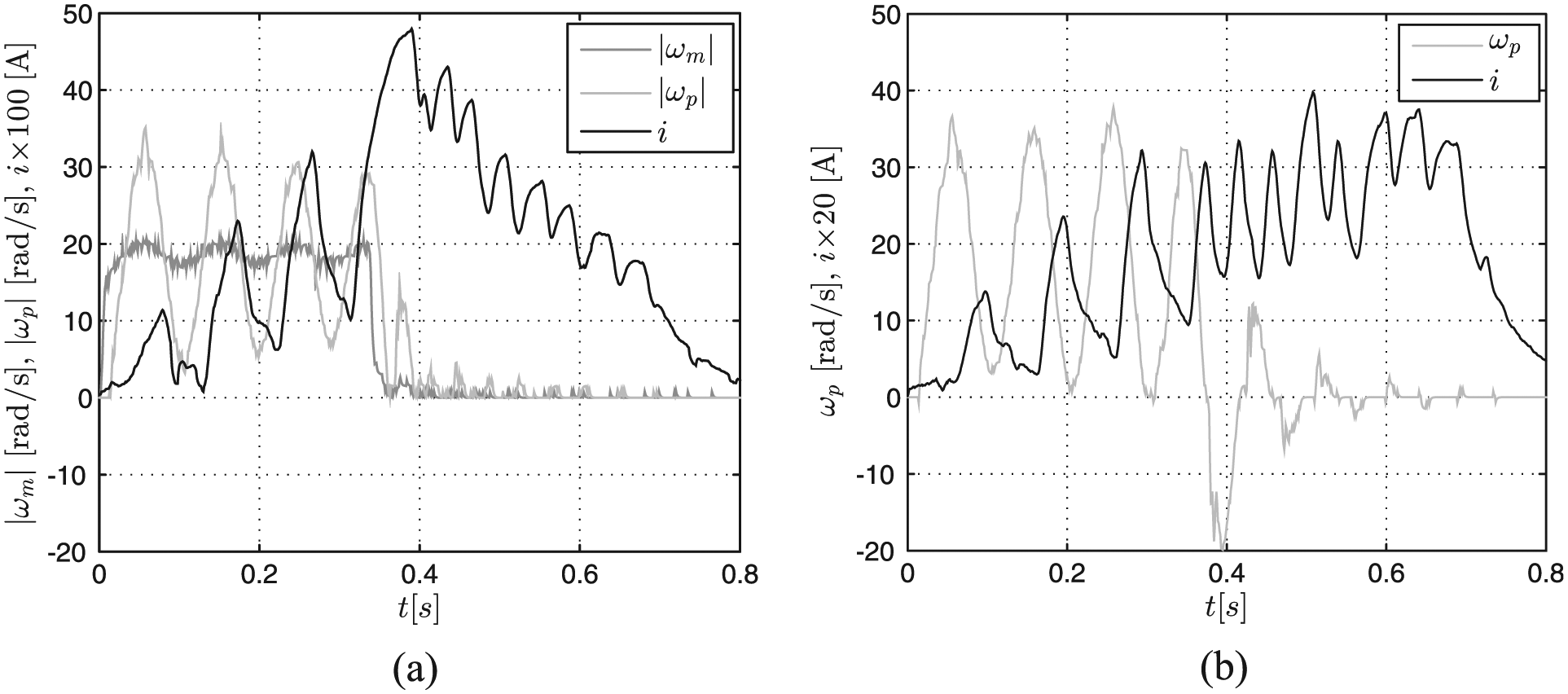
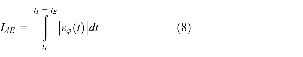
Figure 27 shows the time histories of angular velocity and current level for CA1 and CA2 and Figure 28 for DA1 and DA2. It is readily apparent that the peak value of i in the circuit will not exceed 0.55 A. At the instant the motor shaft reaches the preset position (φp = φset), the object’s velocity is the largest in the case CA1 (19.2 rad/s).
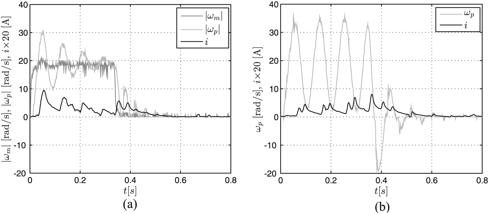
Time histories of velocity
Time histories of velocity
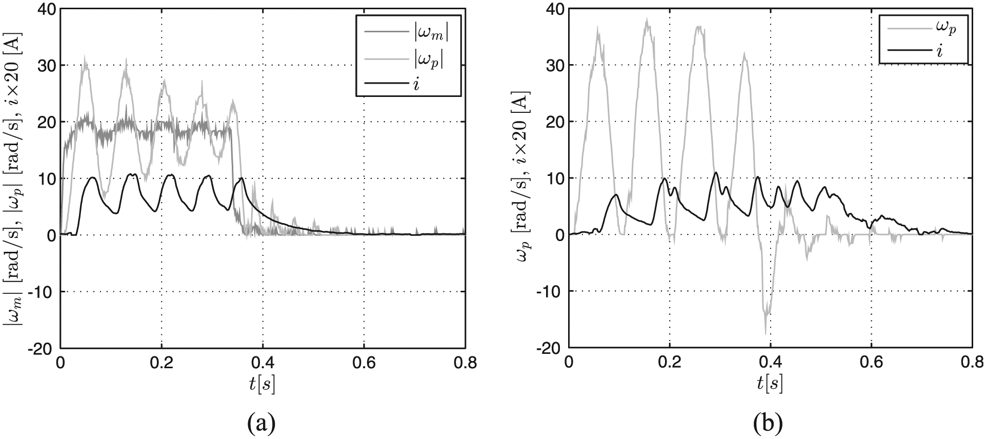
In the next stage, the positioning system’s performance was investigated in the ES2 configuration. Time histories of position φp for CA1 and CA2 are shown in Figure 29(a), for DA1 and DA2 in Figure 29(b).
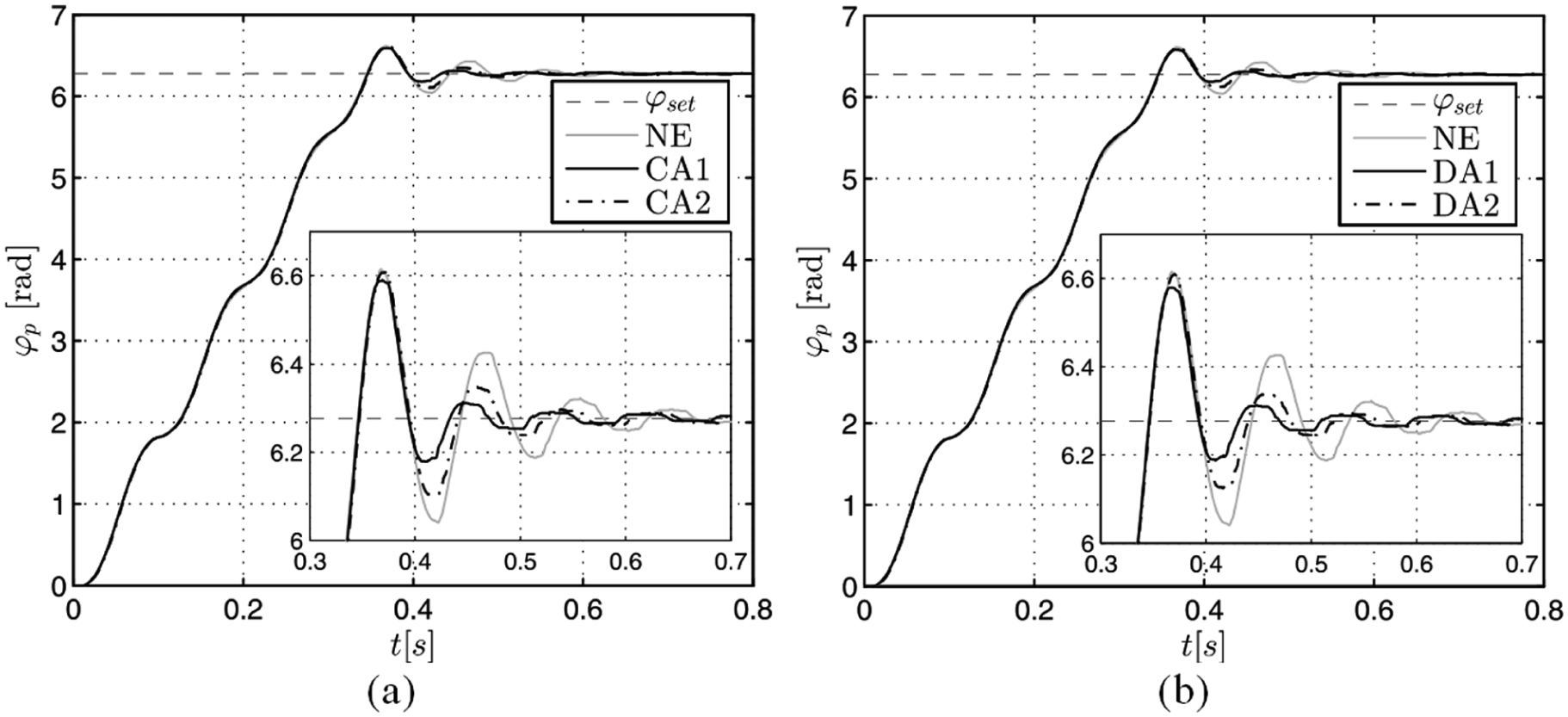
Time histories of the object position φp: (a) continuous control and (b) discrete control; ES2.
Plots in Figure 29 indicate that from the moment t = 0 s, until the moment the control is switched on (φp = φset), in each case the object reaches exactly the same position within subsequent time instants. Throughout this time interval, the generator operates under the idle run. Starting from the moment when φp = φset, the generator begins to operate under load, the control of the damper begins and the relay K (Figure 18). Table 4 summarises the values of tu and φpmax, read out from the plots in Figure 29.
Values of tu and φpmax; structure ES2.
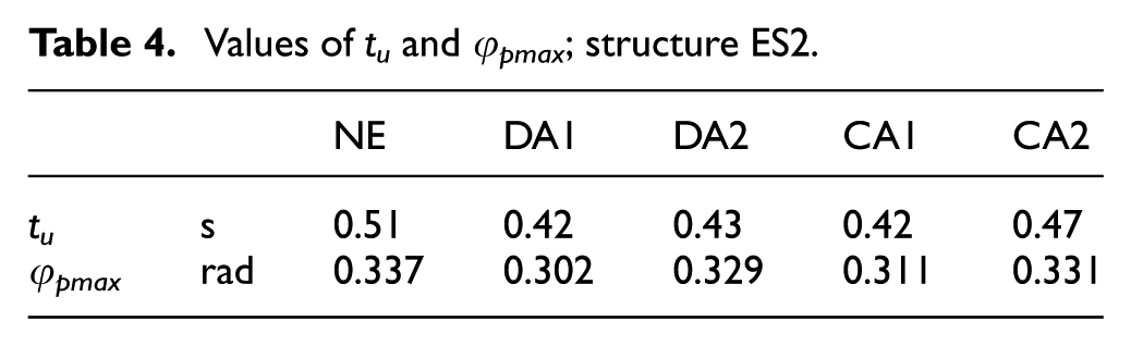
The shortest time tu was obtained in the case DA1 and CA1 (0.42 s). In the case DA1, the overshoot φpmax proved to be the smallest (0.302 rad). Figure 30 illustrating the rate of positioning error decreases clearly indicating that all trajectories tend towards the identical point and that in the case DA1, this point is reached within the shortest time. Figure 31 shows time histories of velocity and current levels for CA1 and CA2; the results obtained in the case DA1 and DA2 are compiled in Figure 32.
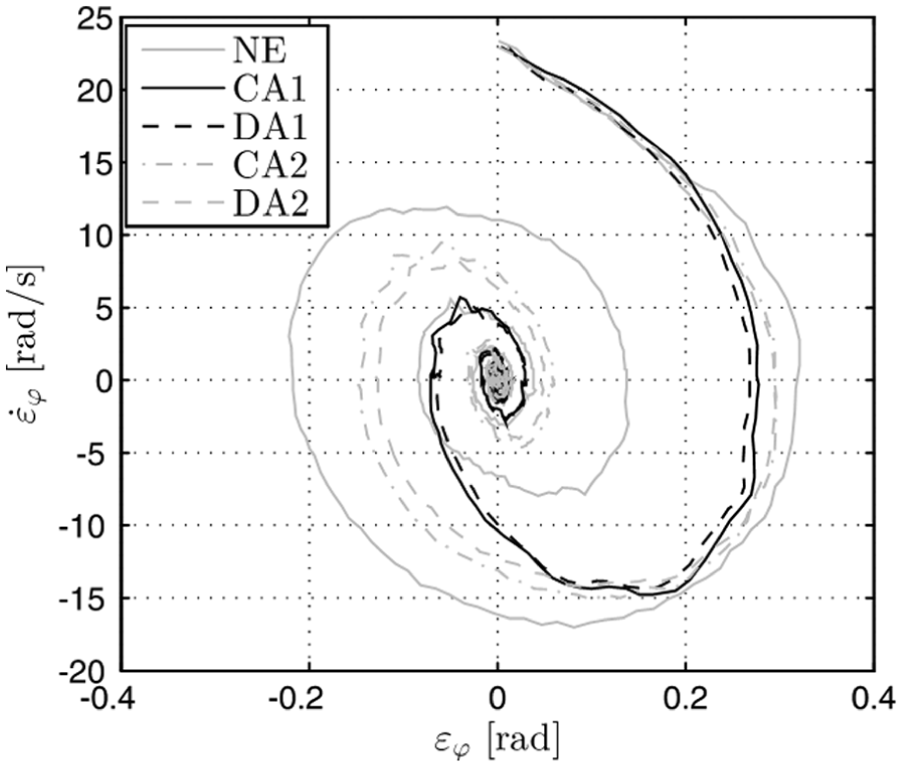
Position error derivative

Time histories of velocity
Time histories of velocity
It is clearly seen (Figures 31 and 32) that in the case ES2, the current flow in the circuit begins at the instant when the motor shaft reaches the preset position. The maximal value of i equals 0.45 A (DA1). It is slightly higher than in the case DG, which is attributable to the generator’s temporarily switching to the idle run mode (DA1) before the current i reaches its peak value, and the relay is disconnected, in accordance with the control algorithm. Time histories of position φp obtained in the case ES3 featuring a 10000 F condenser connected behind the Graetz bridge are shown in Figure 33(a) (CA1, CA2) and Figure 33(b) (DA1, DA2).
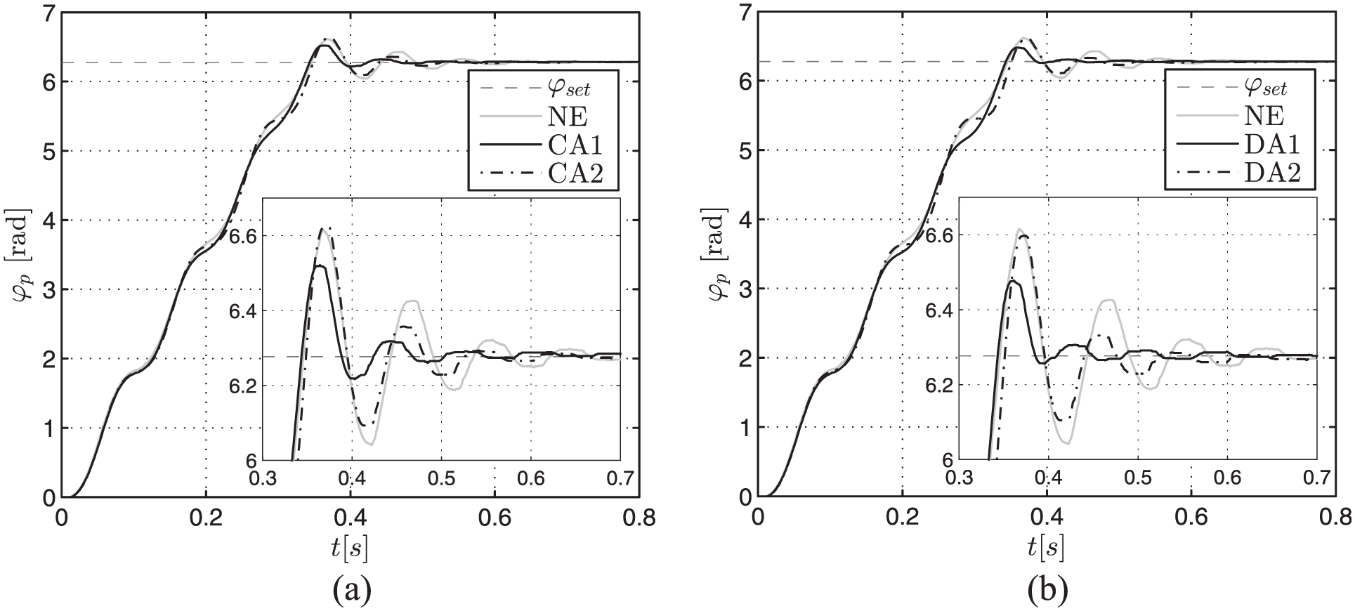
Time histories of object position φp: (a) continuous control and (b) discrete control; ES3.
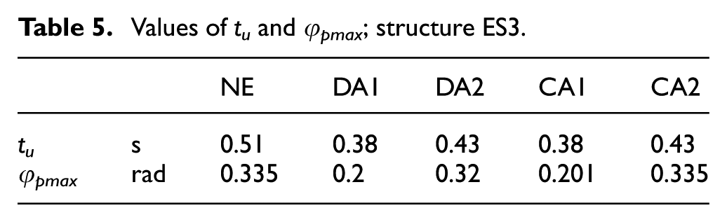
Table 5 compiles the values of tu and φpmax read out from time histories of displacement. It appears that the lowest values of tu and φpmax were obtained in the case DA1 and CA1.
Values of tu and φpmax; structure ES3.
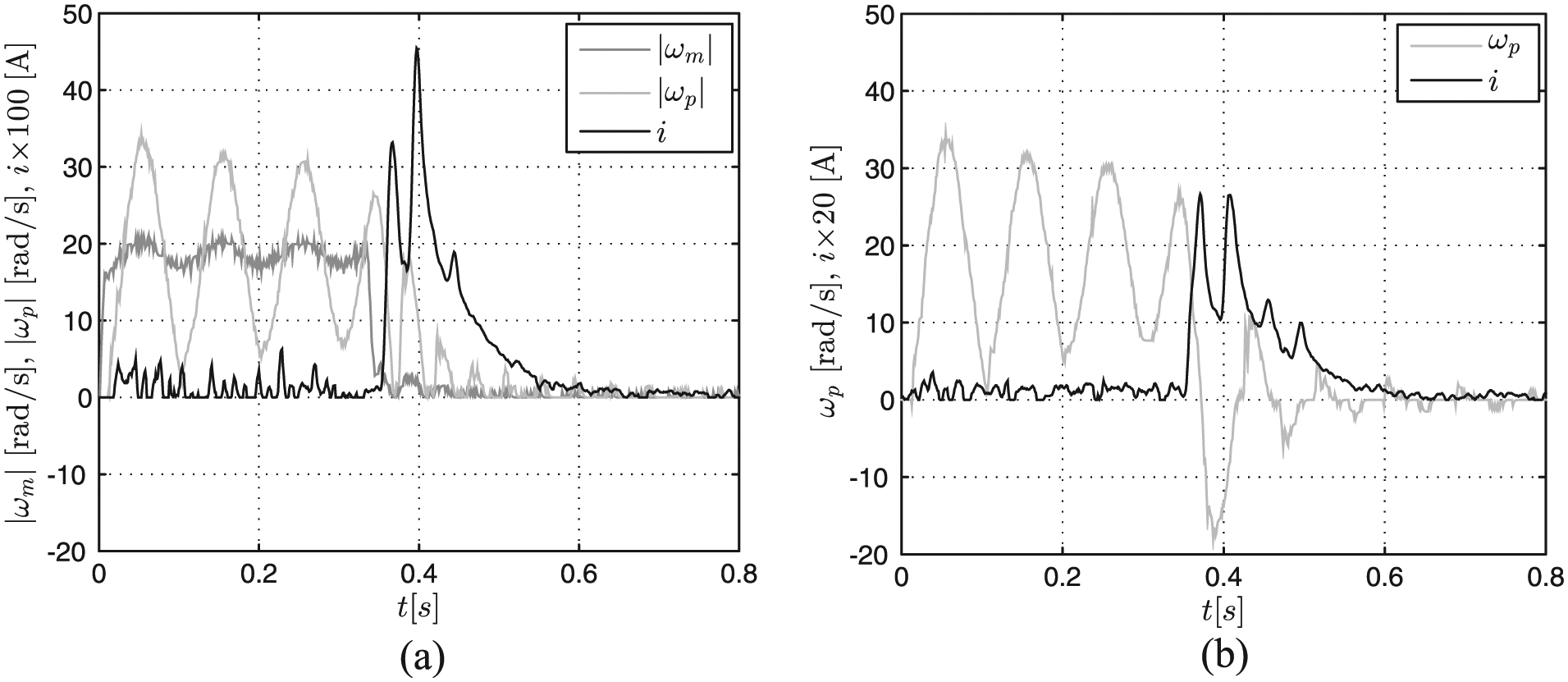
Figures 34 and 35 plot the current i in the control coil, showing that while the object approaches the target position, the variability pattern of i would be similar in each case (CA1, CA2, DA1, DA2). The choice of the control algorithm affects the variability pattern of i is revealed after the motor shaft reaches its target position (φset). The registered current level i is the greatest (0.47 A) in the case DA1.
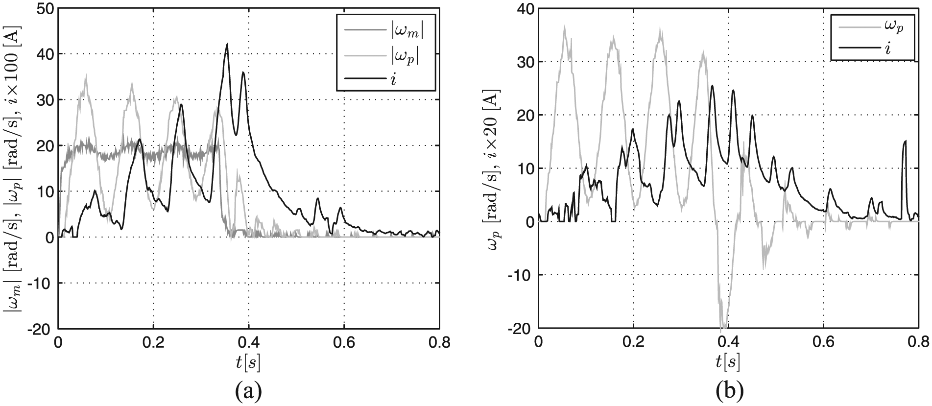
Time histories of the object velocity
Time histories of the object velocity
Comparison of the positioning system’s performance is based on the following indicators
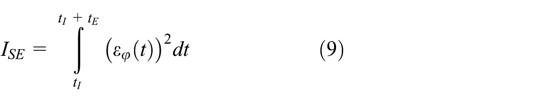
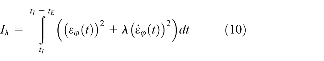
They are expressed such as to allow the evaluation of the control system in terms of selected criteria. Integrands can be interpreted as an instantaneous cost of loss. Introducing a derivative of the control error
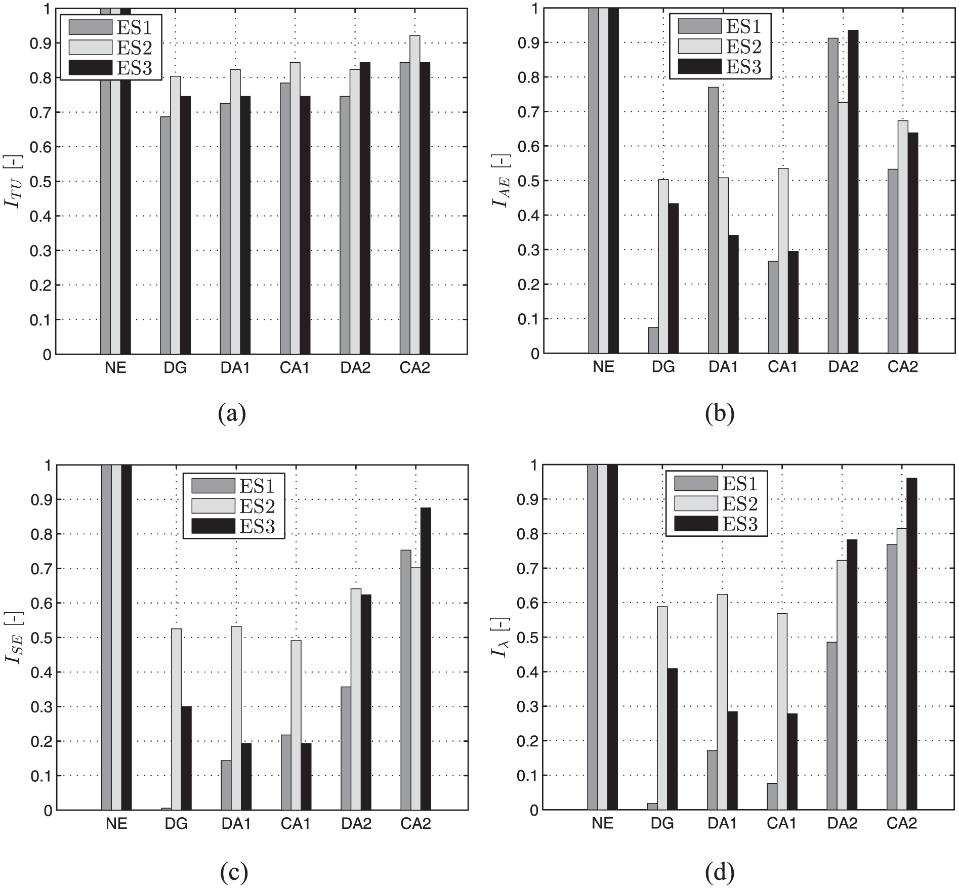
Quality coefficients.
Time tI, for which φm = φset, is taken to be the lower limit of integration while the upper limit is defined as time tE = 0.8 s, after which the object should not oscillate around the preset position. In order that the factors
Summary
The primary goal of this study was to examine the newly developed MR damper–based positioning system through experiments. In particular, the work includes test results of individual system components as well as the damper-generator system under the idle run and under load. The performance of the system was tested in uncontrolled case (passive system) and in the controlled case (semi-active system). The main advantage of the system is its self-power capability, that is, it is adaptable to external excitations without requiring an external power supply.
The results of tests showed that the efficiency of the generator is sufficient for powering (controlling) the damper and indicated that the applied conditioning units (in particular the Graetz bridge) limit the impact of inductive load on the generator’s operation, resulting in higher current levels. Moreover, both the conditioning and control systems enable fast switching between the passive and semi-active mode. The authors found that the system in passive and semi-active mode exhibits improved dynamic behaviour in relation to case with no damper. It was observed that the damper, the generator and the energy management block incorporated in the positioning system enable to control effectively position of the object without interfering in mechanical structure and motor control. The conditioning system allows to switch in between passive mode and semi-active mode very fast. The greatest efficiency of the system in passive mode was achieved when the Graetz bridge was placed between the power generator coil and the damper coil. In semi-active mode, the system was most effective when the continuous (CA1) and discrete (DA1) algorithm were employed.
Further research efforts will be focused on application of the investigated positioning system in a special clutch or machine safety systems.
Footnotes
Declaration of conflicting interests
The author(s) declared no potential conflicts of interest with respect to the research, authorship and/or publication of this article.
Funding
The author(s) disclosed receipt of the following financial support for the research, authorship, and/or publication of this article: This work is supported by AGH University of Science and Technology under research program no. 11.11.130.958.