
Abstract
The present contribution is devoted to the study of the influence of shape memory alloys on the dynamic behavior of flexible rotors. In this sense, a suspension composed by pseudoelastic shape memory alloy wires that are connected to a rotor-bearing test rig was designed. To evaluate the performance of the system, both numerical and experimental investigations are carried out. The suspension stiffness can vary, especially in the pseudoelastic region, so that this variation takes place per a hysteretic cycle denoting energy dissipation whenever the loading magnitude is sufficient to induce a phase transformation. The constitutive model used to describe the shape memory alloy behavior is a modified version of the Brinson model for the one-dimensional case. To provide all thermomechanical properties of shape memory alloy wire, a complete characterization process was performed. Due to numerical reasons, the size of the model of the rotating system was reduced. Finally, numerical and experimental results demonstrate the success of shape memory alloy applied to the suspension of rotating machines as an interesting alternative for vibration control.
Keywords
Introduction
The use of smart materials with the intention of mitigating vibration in rotating machines has been increasingly investigated by various researchers. However, there is a category of material still not fully explored for this purpose, namely, the shape memory alloy (SMA), which points out a new direction in the field of vibration control of rotating machines. SMA exhibits characteristics of shape memory and pseudoelasticity depending on the thermomechanical state. Thus, its stiffness can vary, especially in the pseudoelastic region, where this variation takes place, per a hysteretic cycle denoting energy dissipation, once the crystallographic structure migrates from austenite to martensite (and vice versa) whenever the loading magnitude is sufficient to induce this phase transformation.
These capabilities of SMA with respect to rotating machines have been previously investigated in a few publications. Nagaya et al. (1987) are some of the pioneers in using this family of materials applied to vibration control of rotors. They used SMA springs to change the bearing support stiffness by either heating or cooling the springs. Liu et al. (1994) investigated and proposed the use of SMA wires attached to the housing of hydrodynamic bearing to control the vibration, so that its stiffness reduces (softening) while the rotor accelerates and increases (hardening) while the rotor slows down. Both the behaviors are nonlinear, and the pseudoelastic SMA wires play the role of energy dissipation device. Nie and Yan (2000) designed a smart support system to pass through critical speeds of an aeroengine. The principle of operation is based on an active switching of stiffnesses, where the SMA wires work as actuators. In this way, the engine has two different stiffness connections, so that this characteristic is useful to switch conveniently the stiffness in run-up and run-down operations to reduce the vibration amplitude when crossing the critical speeds. In their work, Gupta et al. (2003) propose the employment of SMA wires embedded in shafts composed by epoxy resin and fiberglass to modify their stiffness. The wires are stretched before they are embedded into the shaft so that an axial compression is induced, increasing its stiffness. Then, using electric current, it is possible to change the shaft stiffness conveniently. He et al. (2007a, 2007b) proposed a self-optimizing support system where SMA springs are used to construct a bearing pedestal. In addition, using the principle of dynamic vibration absorbers they calculated and changed the stiffness of the pedestal to set the rotor-bearing system close to the anti-resonance condition. Lees et al. (2007) applied SMA to a bearing pedestal by means of a winding of wires to change its stiffness by Joule effect. Atepor (2008) applied SMA elements integrated within glass epoxy composite plates and shells resulting the design of a novel smart bearing based on the principle of antagonistic action. Zhu et al. (2009) developed and applied a model based on multi-variate statistical analysis vibration control of rotor systems with SMA. More recently, Borges et al. (2013) used helical springs made of SMA to control the vibration of a flexible rotor. They employed the general concept of dynamic vibration absorbers to model the system, so that the mass of the bearing where the SMA springs are located is considered as the secondary mass. Besides, a control law based on fuzzy logic was employed, in such a way that the transfer function correlates the spring temperature with its stiffness. In the same year, Silva et al. (2013) investigated the behavior of a rotordynamic nonsmooth SMA system where it is modeled as a Jeffcott rotor with two degrees of freedom (DOFs). The focus relied on a comparison between the rotor responses with linear elastic support and those from the rotor with an SMA support. In addition, the dependence on the temperature was also investigated. It is noteworthy to mention that both compression and tension actions on the SMA element were allowed. Ma et al. (2014) described the design, manufacturing, and evaluation of a smart support with elements of SMA. Based on this concept, the support can provide both variable stiffness and damping with respect to three parameters, namely: temperature, vibration amplitude, and excitation frequency. Enemark et al. (2015) investigated experimentally how pseudoelastic SMA springs influence the dynamic behavior of a rotor-bearing system with low damping due to passive magnetic bearings. It was observed that the higher the temperature, the stiffer the support. In addition, the hysteretic behavior of the system was evaluated. Therefore, both the amplitude responses through the critical speeds and the mode shapes were changed in order to reduce vibration. As an extended version of above-mentioned paper, Enemark and Santos (2016b) presented a deeper analysis by comparing theoretical and experimental results proving, in terms of vibration suppression, the advantage of applying SMA to a rotor-bearing system. Yogaraju et al. (2016), based on experimental studies, observed that SMA can be used as a medium to apply necessary forces at identified locations to obtain the desired profile shapes for a multi-lobe bearing configuration facilitating the development of semi-active journal bearings. Finally, Yuan et al. (2017) presented a very detailed review about actuators driven by SMA, more specifically rotary actuator, highlighting its specificities and potentialities for new applications in the future. Thus, a rotating machine could be benefited by some of the concepts explored.
The present contribution deals with study of dynamic behavior of a horizontal rotor-bearing system suspended by SMAs pseudoelastic wires, in order to verify the feasibility of either passive or semi-active control devices for rotating machines in the future. In terms of control, the strategy is based upon the change of stiffness by heating/cooling the suspension and the addition of some damping by cyclic phase transformation due to mechanical loading. The performance of the proposed system is investigated for the following conditions: rotor at steady-state motion with several temperatures, rotor at steady-state motion with varying temperature and transient motion with several temperatures. To be effective, the suspension by pre-tensioned wire (SPW) is mounted along the horizontal plane, and it is located at the position of one of the rotor bearings. To reduce the computational cost, the size of the rotor model obtained from finite element method (FEM) is reduced by neglecting the higher modes. The constitutive model used to describe the SMA behavior is a modified version of the model by Brinson for the one-dimensional (1D) case, as performed by Enemark et al. (2014).
This article is organized according to five sections, as follows. After a brief overview presented in the introduction, the rotor model is derived using the FEM; the concept of suspension system, its characteristics, and its modeling are then presented; a comparison between numerical and experimental results is discussed; and finally, the conclusions are summarized.
The experimental apparatus
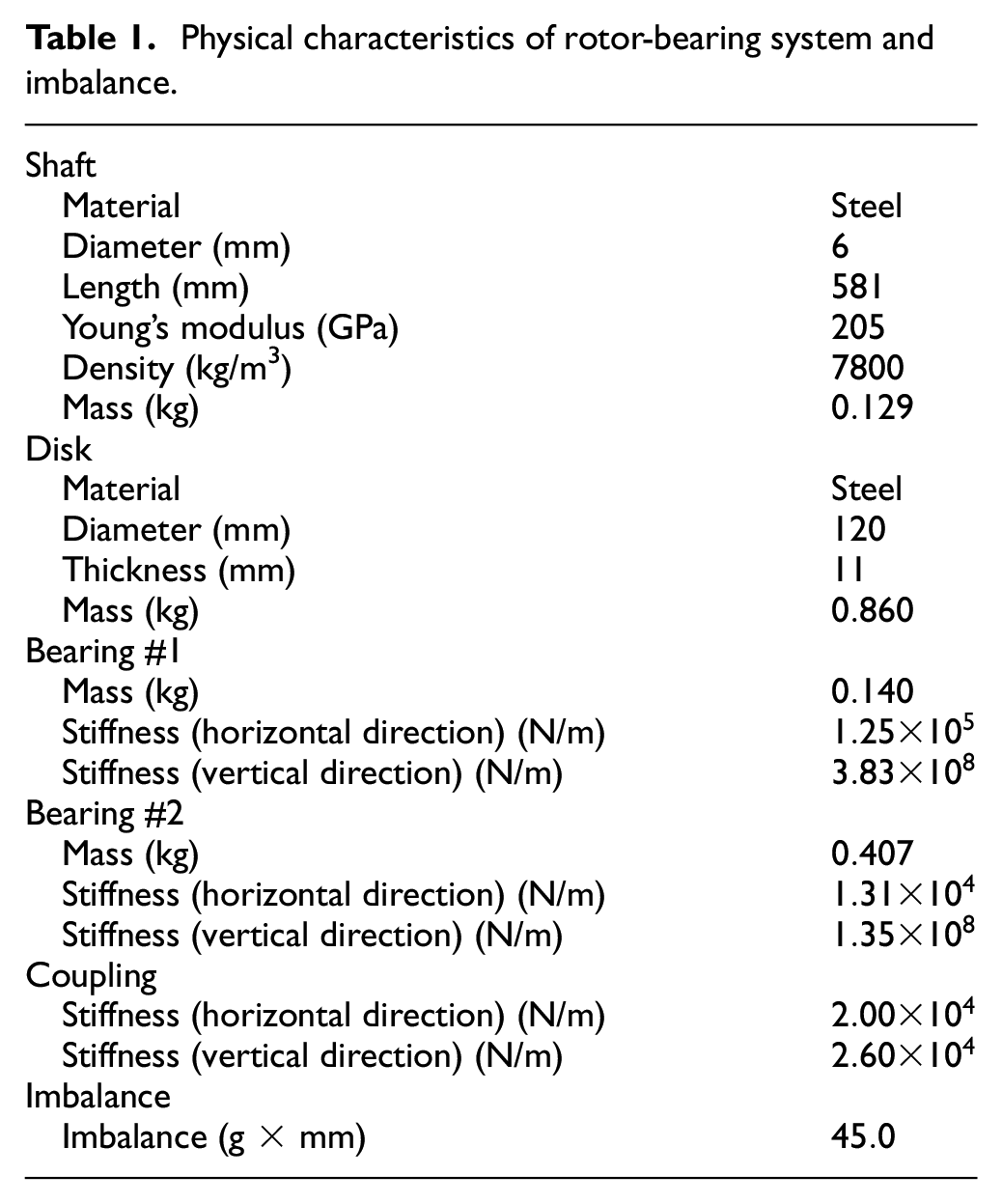
Figure 1 depicts an overview of the experimental apparatus, highlighting the main parts of the test rig. Basically, it is encompassed by a flexible rotor-bearing system, a heating device, and the rotor suspension. As designed by Alves (2015), the suspension, composed of pre-tensioned wires, is encapsulated inside a heating chamber to keep the temperature of the air from the heat gun under control, as detailed in Figure 2. The main physical properties related to the rotor-bearing system are shown in Table 1. The SMA wires are made of nickel and titanium (Ni-Ti alloy), whose total length is
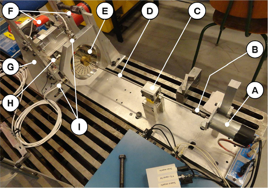
Experimental apparatus: (A) DC motor/encoder; (B) coupling; (C) bearing #1; (D) flexible shaft; (E) disk; (F) heat guns; (G) suspension system; (H) accelerometer; and (I) proximity probes.
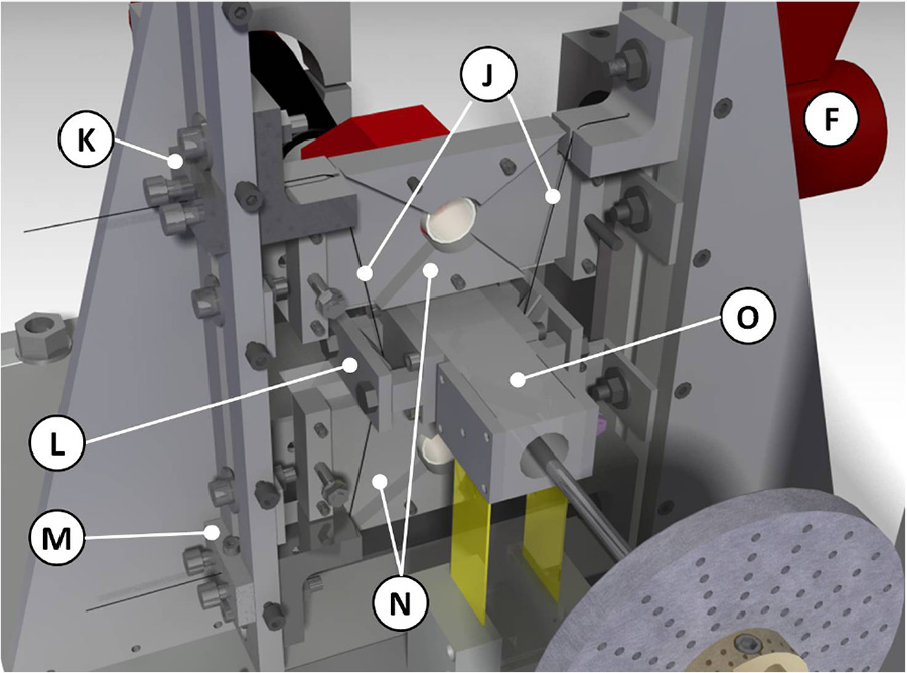
Detailed view of suspension by pre-tensioned wires (SPW): (F) heat gun; (J) PE SMA wires; (K), (L), and (M) tensioners; (N) heating chamber; and (O) bearing #2.
Physical characteristics of rotor-bearing system and imbalance.
The suspension of bearing #2 is composed basically of a bearing housing supported by a flexible frame composed by two steel rulers, as can be seen in Figure 3. In spite of the fact that most of the bearings have similar stiffnesses in both directions, this concept was adopted to allow high amplitude of vibration along to the horizontal plane, since the architecture of the suspension was designed to work on the same plane. Thus, based on strength of materials, a relationship between axial (vertical direction) and flexural (horizontal) stiffnesses
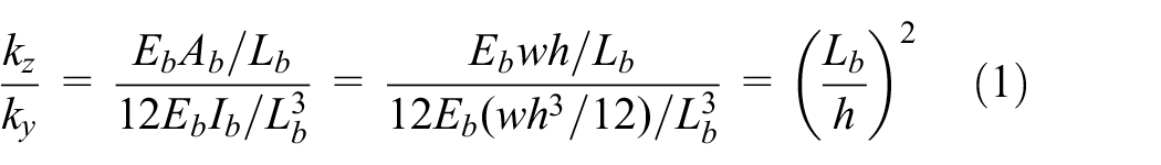
where, for the steel ruler,
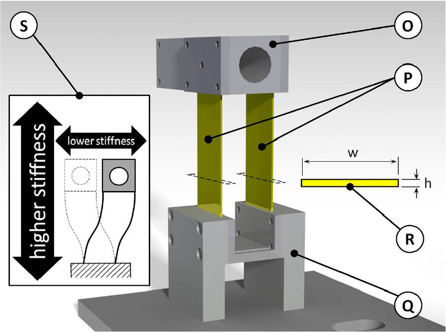
Detailed view of bearing #2: (O) bearing #2’s housing; (P) flexible frame; (Q) bearing #2’s base; (R) steel ruler’s cross section; and (S) schematic comparison between flexural and axial stiffnesses.
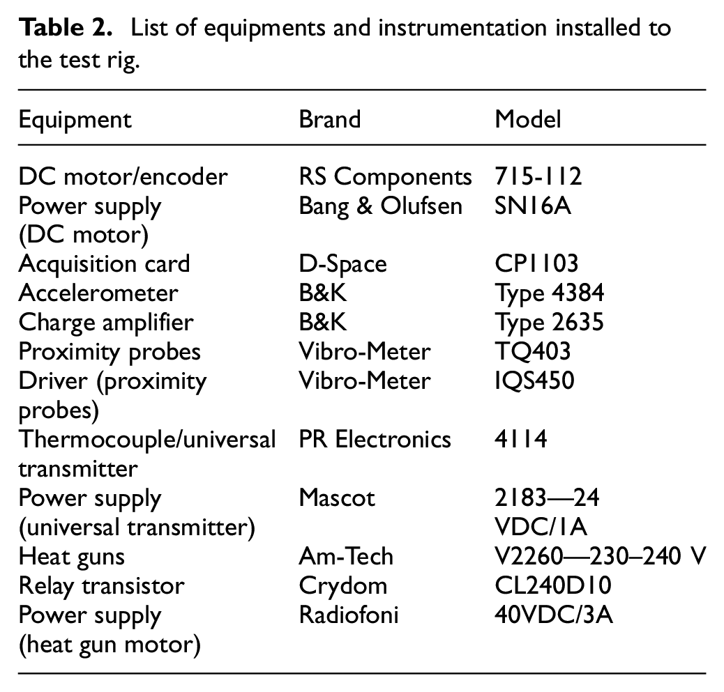
List of equipments and instrumentation installed to the test rig.
System modeling
The models used to describe the behavior of the complete system are presented separately, according to each sub-system. First, the rotor formulation and its properties are shown. Then, the general characteristics and properties of the suspension, as based on pre-tensioned wires, are discussed. Finally, the truncation criteria and the reduced model of the complete system are presented.
Rotor model
The dynamic response of the considered mechanical system can be modeled using variational mechanics equations as based on the Hamilton’s principle. For this aim, the strain energy of the shaft and the kinetic energies of the shaft and disks are calculated. An extension of Hamilton’s principle makes possible to include the effect of energy dissipation. The parameters of the bearings are considered in the model using the principle of the virtual work. For computation purposes, the FEM is used to discretize the structure so that the energies calculated are concentrated at the nodal points. Shape functions are used to connect the nodal points. The model obtained as described above is represented mathematically by the set of differential equations (Lalanne and Ferraris, 1997) given by equation (2)

where
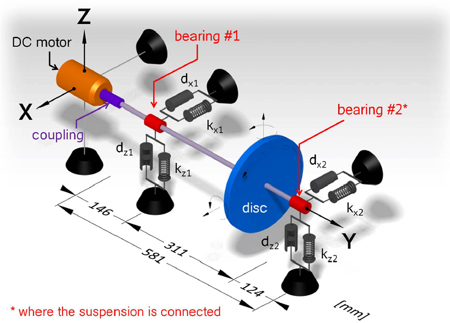
Schematic of the rotor-bearing system.
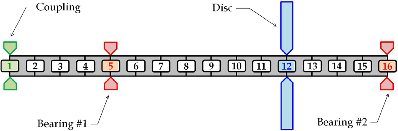
Schematic of shaft discretization.
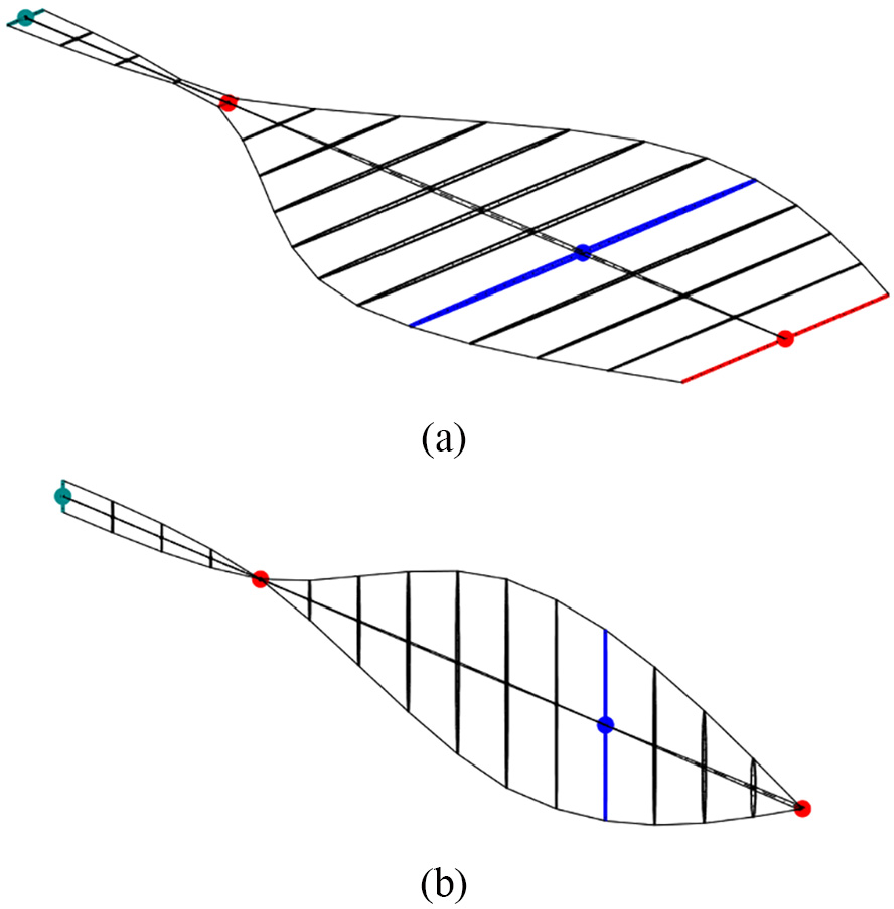
Mode shapes of the rotor-bearing system: (a) first mode and (b) second mode (green node → coupling; red nodes → bearings; and blue node → disk).
SMA constitutive model
The behavior of SMA for the 1D case is described by the constitutive models proposed by Brinson (1993), Brinson and Huang (1996), and Bekker and Brinson (1998). In this article, the focus is on the pseudoelastic behavior of the material. Thus, we can neglect the twinned martensite since the lowest operational temperature (room temperature) is higher than the martensitic start temperature

where
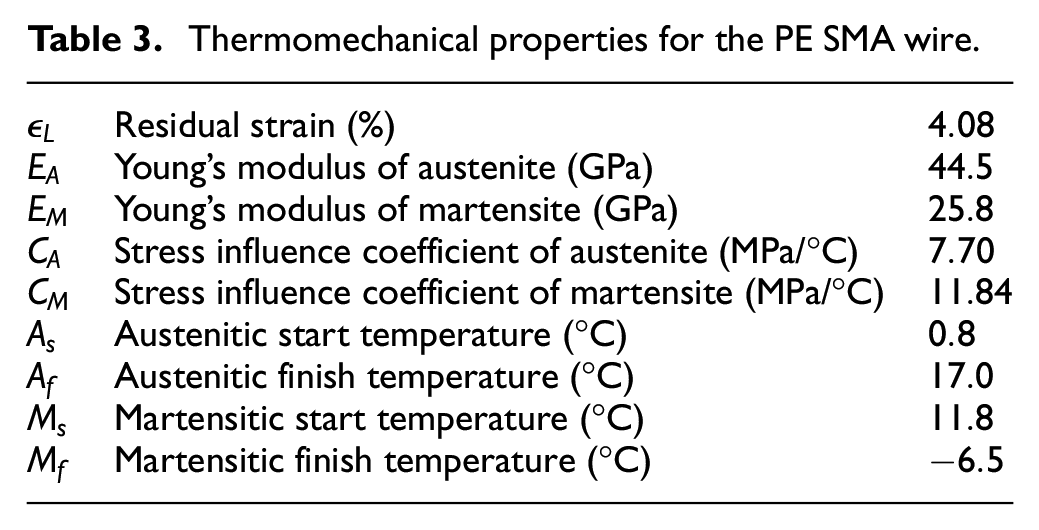
Thermomechanical properties for the PE SMA wire.
During the forward transformation, the evolution of the martensite volume fraction


For the reverse transformation, one has


where
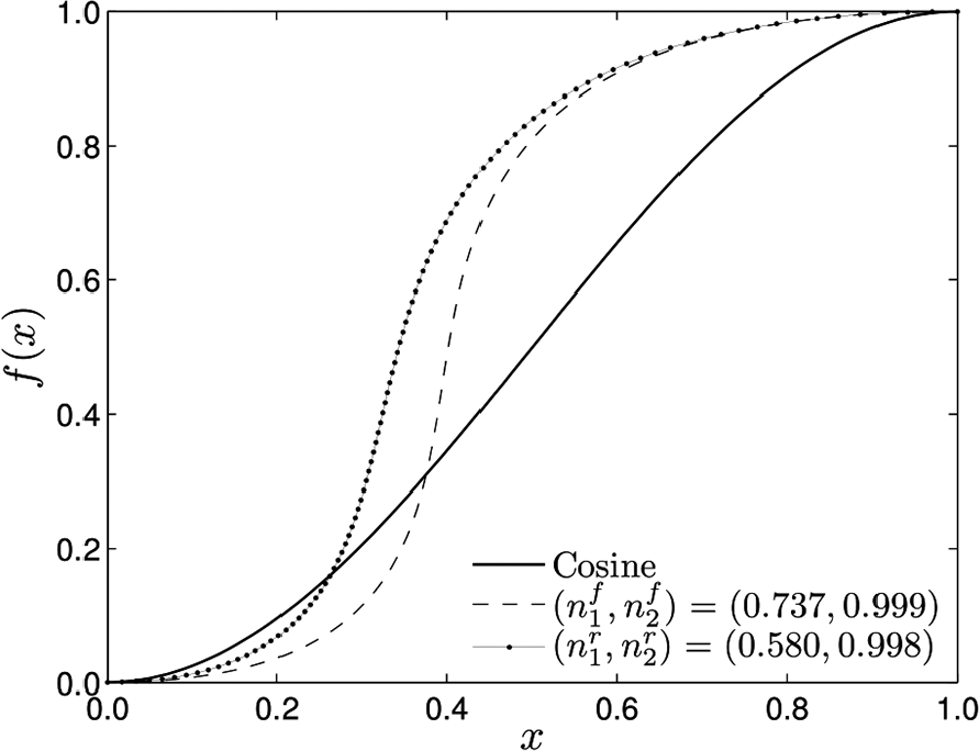
Hardening functions in the forward and reverse transformations.
The pseudoelastic SMA wires used in this contribution were purchased from website Amazon® accessing directly http://www.amazon.com/dp/B001385FYY/, and all their thermomechanical properties can be found in Table 3.
Thermomechanical characterization
Thermomechanical analysis of SMAs needs to establish a proper characterization that can identify the main aspects of the SMA. Basically, different experimental tests are developed to perform the characterization. Phase transformation temperatures are usually measured from differential scanning calorimetry (DSC) tests. Mechanical properties are evaluated from mechanical tests, usually performed with a universal testing machine.
Temperature plays an essential role in the thermoelastic martensite phase transformation and, therefore, physical properties, such as the electrical resistivity and elastic modulus, change with temperature. The determination of thermal properties is fundamental to the design of actuators based on SMAs, targeting advanced applications.
DSC analysis
The Netzsch® DSC 200 F3 is the calorimeter model used to characterize the Ni-Ti wires of the test rig.
DSC test analyzes phase temperature of SMA sample by monitoring temperature and heating. The SMA sample is placed in a small crucible and measurements are compared with a reference sample, that can be a stable metal without phase transformation in the temperature range examined. The calorimeter makes measurements of temperature and energy occurring during the process, rate of
A typical measurement of the DSC test is presented in Figure 8 that shows phase transformation temperatures:
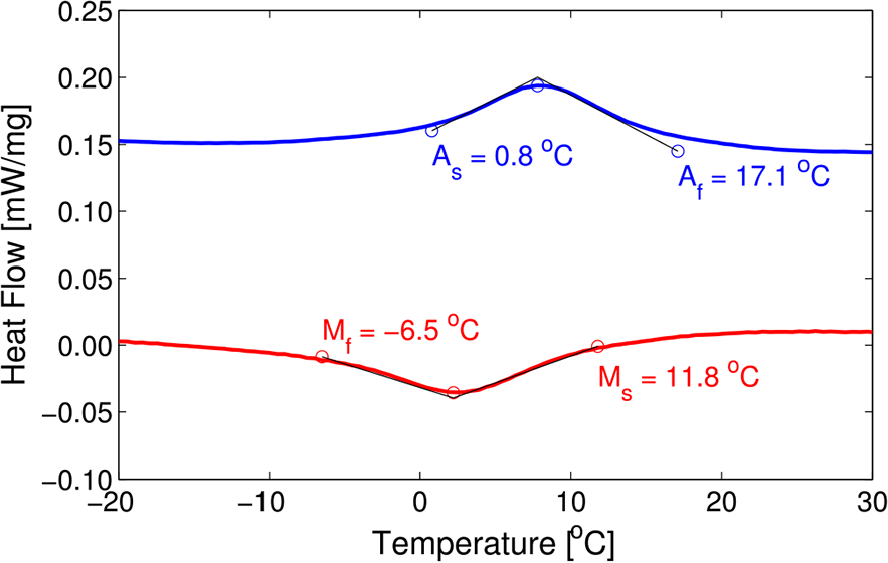
Differential scanner calorimetry test of the SMA wire.
Isothermal stress–strain tests
Mechanical properties are usually evaluated from universal testing machines. Cyclic tensile tests are performed using an INSTRON® Model 5902 with an environmental chamber. Figure 9 shows the stress–strain curve at temperatures around
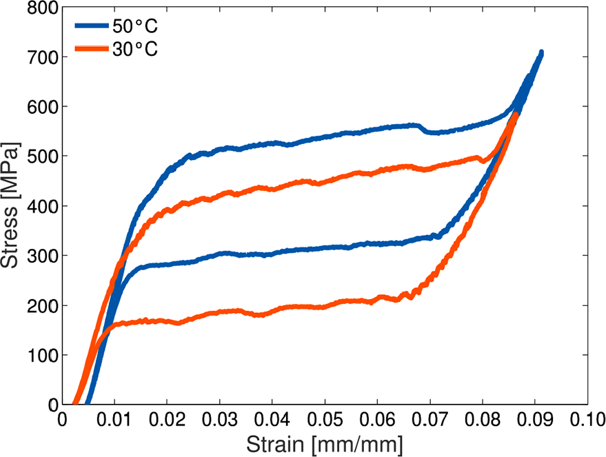
Tensile test of the SMA wire.
According to Brinson (1993), the constants
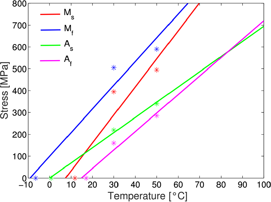
Table 3 presents a summary of the thermomechanical characterization.
Suspension by pre-tensioned wires model
Both Figures 11(a) and (b) illustrate schematically how the suspension (SPW) is connected to the bearing #2. Besides, these two figures illustrate the geometry of the suspension. In addition, some basic parameters for the problem formulation, such as
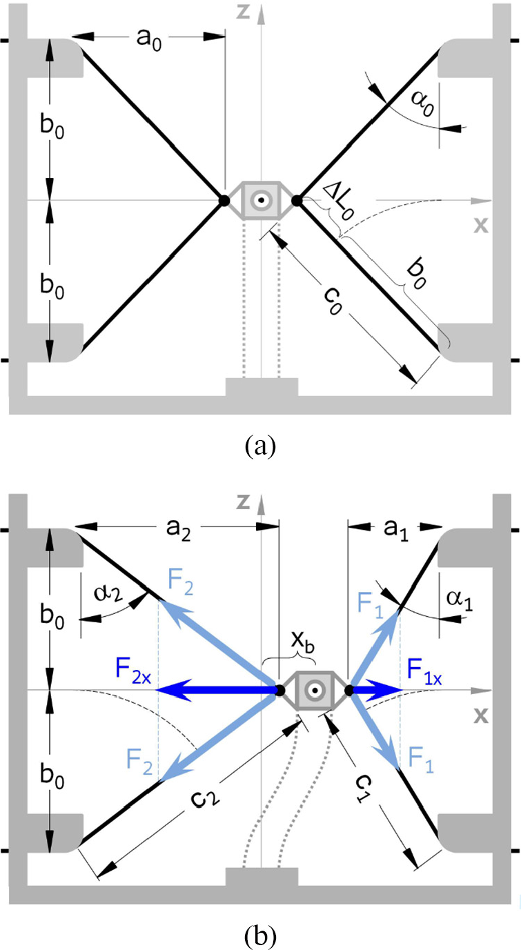
Schematic of the suspension system (SPW): (a) rotor at rest and (b) rotor in operation (dotted lines → flexible frame).
Consequently, based on the aforementioned figures, the elongation of the wire can be expressed by
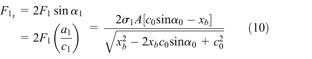
whereas the antagonistic force

where

As can be noticed, the forces
Calculating the pre-tension in the SPW
Here, using the formulation for the current SMA constitutive model together with the geometry of the SPW, two graphs are generated. The first relates the martensite volume fraction
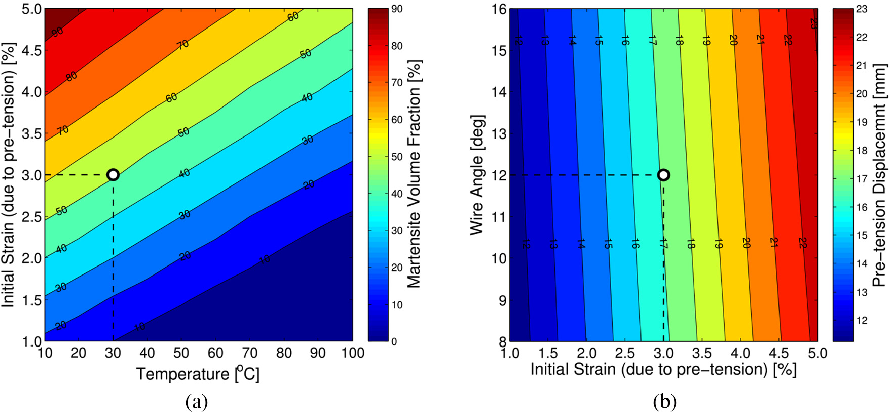
(a) Martensite volume fraction with respect to the initial strain (due to pre-tension) and to the temperature
Results and discussion
The performance of the suspension (SPW) was tested for four operating conditions, namely, rotor at rest and transient rotation (run-up) for three different temperatures, besides steady-state rotation at first critical speed for several temperatures, and steady-state rotation at first critical speed with varying temperature. For the first test, the excitation comes from an impact, and for the other cases, the excitation is provided by the unbalance.
Impulse response with the rotor at rest for several temperatures
This test was performed with the rotor at rest for several temperatures, namely:
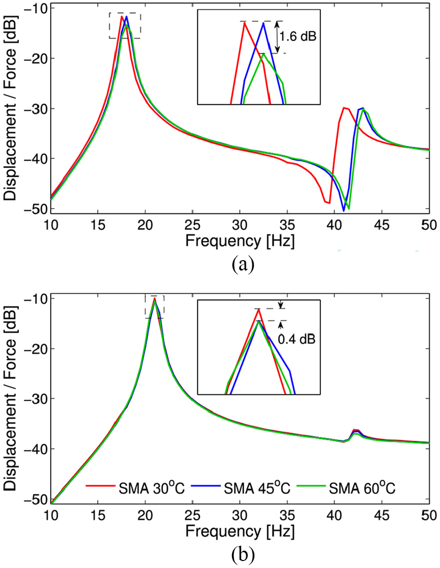
Experimental FRFs (estimated): (a) horizontal direction and (b) vertical direction.
For this analysis, it is important to consider two points, namely: the phase transformation of SMA is dependent on the thermomechanical loading, and the suspension is only effective along to the horizontal direction. For the first mode, as shown in Figure 13(a), from the temperature
Summary for impulse response results—natural frequencies.
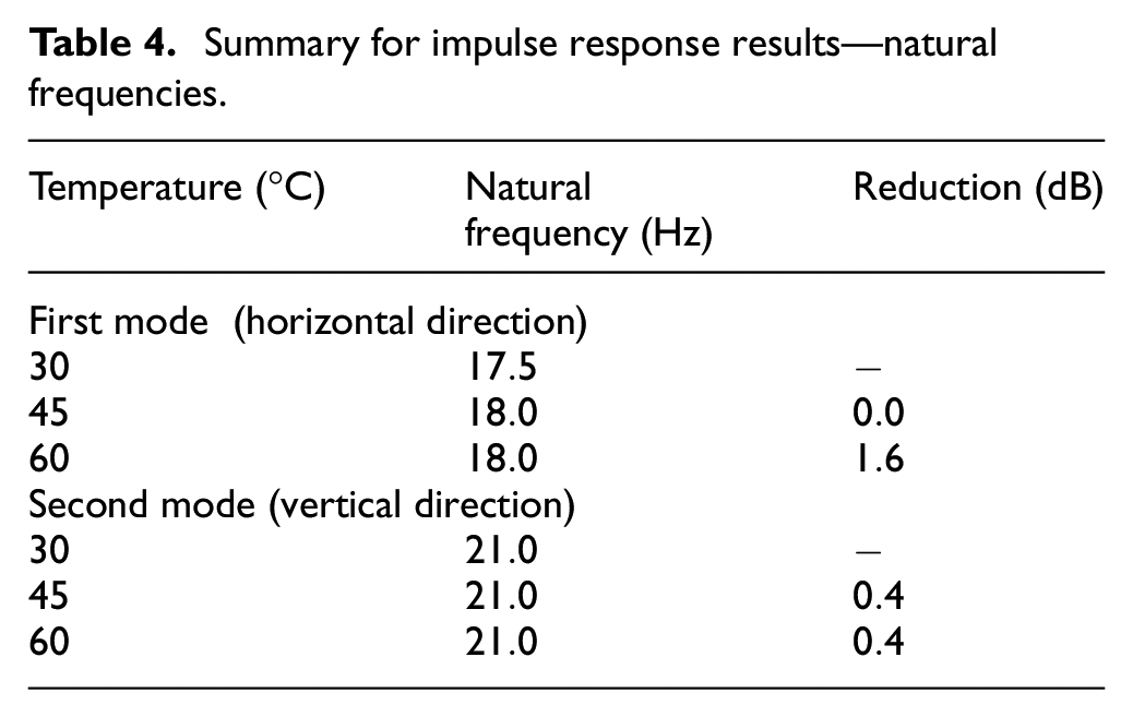
Based on the constitutive model evaluated in this contribution, the dynamic behavior obtained was expected from theory, once that, the higher the temperature, the lower the martensite volume fraction. In other words, the alloy (pseudoelastic wire) becomes stiffer since Young’s modulus for the austenitic phase is
Steady-state response at first critical speed for several temperatures
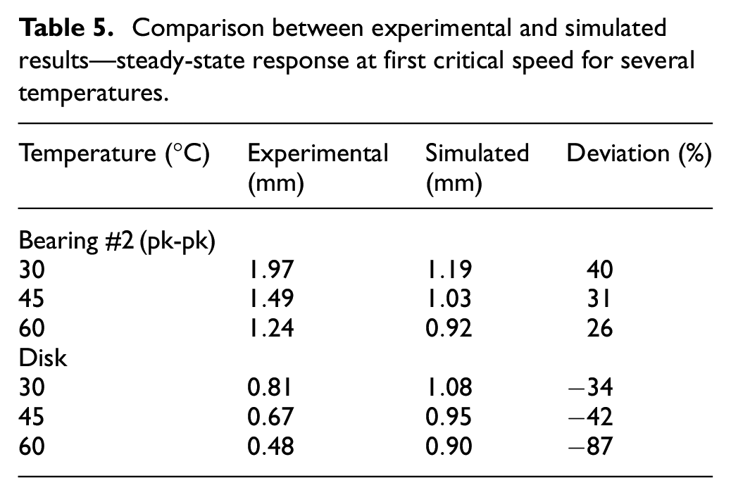
This section presents both simulated and experimental steady-state responses for several temperatures, as depicted in Figures 14 and 15, respectively. The focus herein lies on showing only the responses along the horizontal direction. This decision is based on two reasons: first, only the first mode (that takes place along this direction) was evaluated in this contribution; second, the suspension (SPW) is only effective in this same direction. The alternative way to show these results is presented in Table 5, where the deviation rates are calculated considering experimental results as a reference.
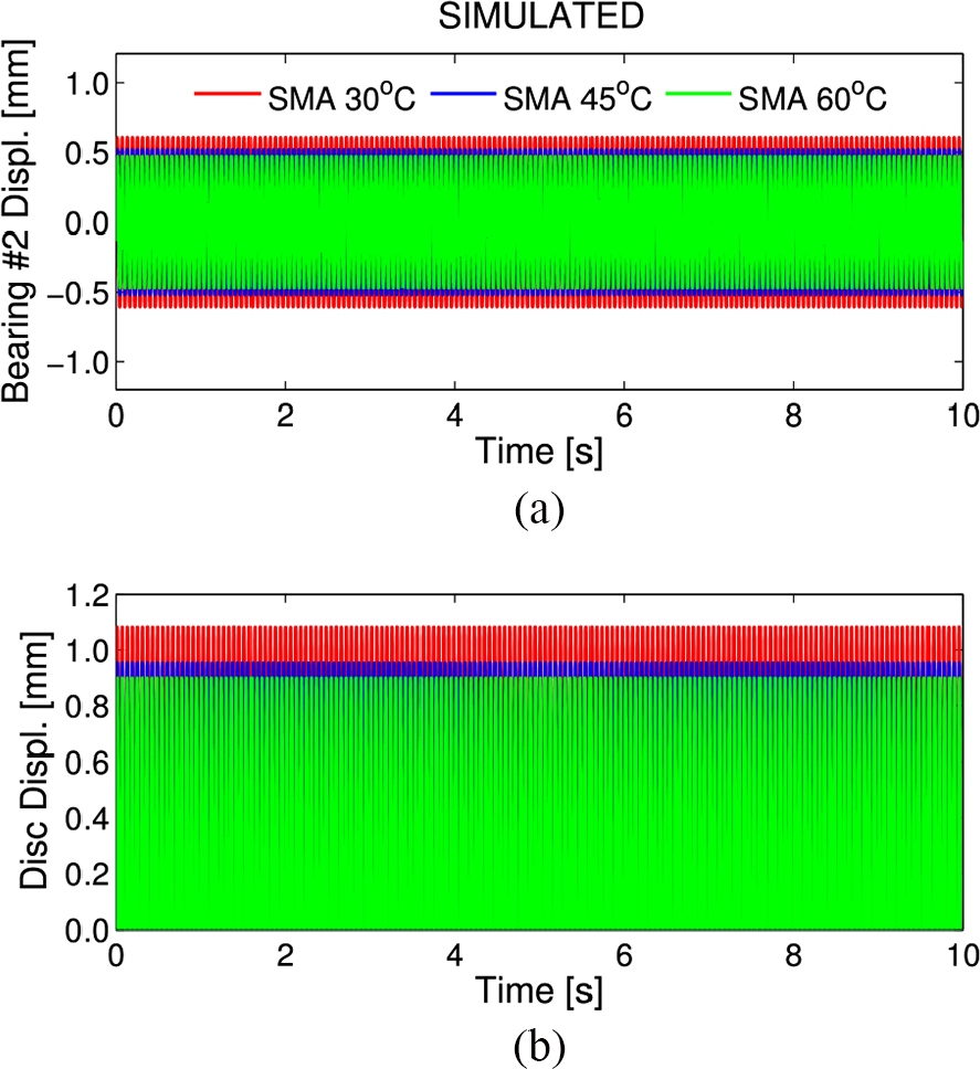
Simulated steady-state response at first critical speed and constant temperature in the SPW: (a) bearing #2 displacement (node #16) and (b) disk displacement (node #12).
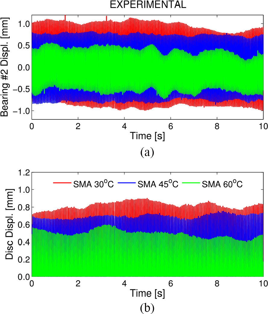
Experimental steady-state response at first critical speed and constant temperature in the SPW: (a) bearing #2 displacement and (b) disk displacement.
Comparison between experimental and simulated results—steady-state response at first critical speed for several temperatures.
In this case, from the point of view of vibration control, the suspension (SPW) accomplished its task. This statement is based on the results conveyed. In this operating condition, the vibration level is the highest, and for this reason, the phase transformation takes place during all the time test. Figure 16 shows that hysteresis loop is more upward inclined for the higher temperature, such that the higher the temperature, the stiffer the suspension. It is worth mentioning that the shaft of the rotor-bearing system used in this work is very thin (only 6 mm) and therefore very flexible. In this case, by assuming a conventional material for the wire (such as the steel), as the bearing stiffness increases, the vibration amplitude of the disk increases as well (Muszynska, 2005). However, using pseudoelastic SMA wires, a stiffer suspension was capable of providing lower vibration amplitude for the disk, in such a way that it can be concluded that the main reason for the reported reductions is most likely due to energy dissipation.
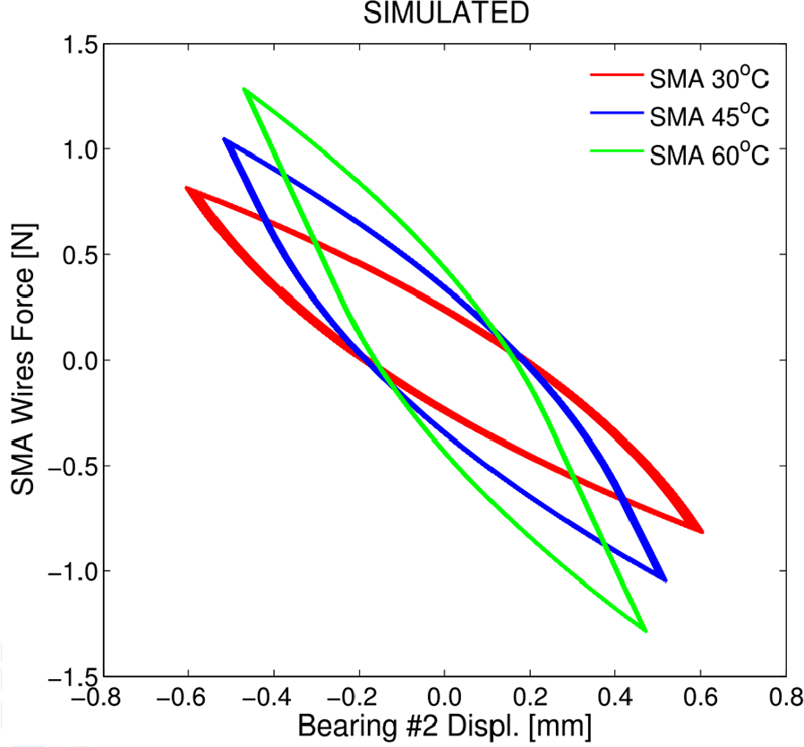
Simulated hysteresis loop at first critical speed and constant temperature in the SPW.
Steady-state response at first critical speed with varying temperature
In this section, the results for numerical and experimental evaluations are presented. Here, the rotor operates at constant speed of rotation, and the suspension is submitted to varying temperature. It is important to say that the idea was to operate the rotor as close as possible to the first natural frequency. For this reason, in both cases, the speed of rotation was shifted only
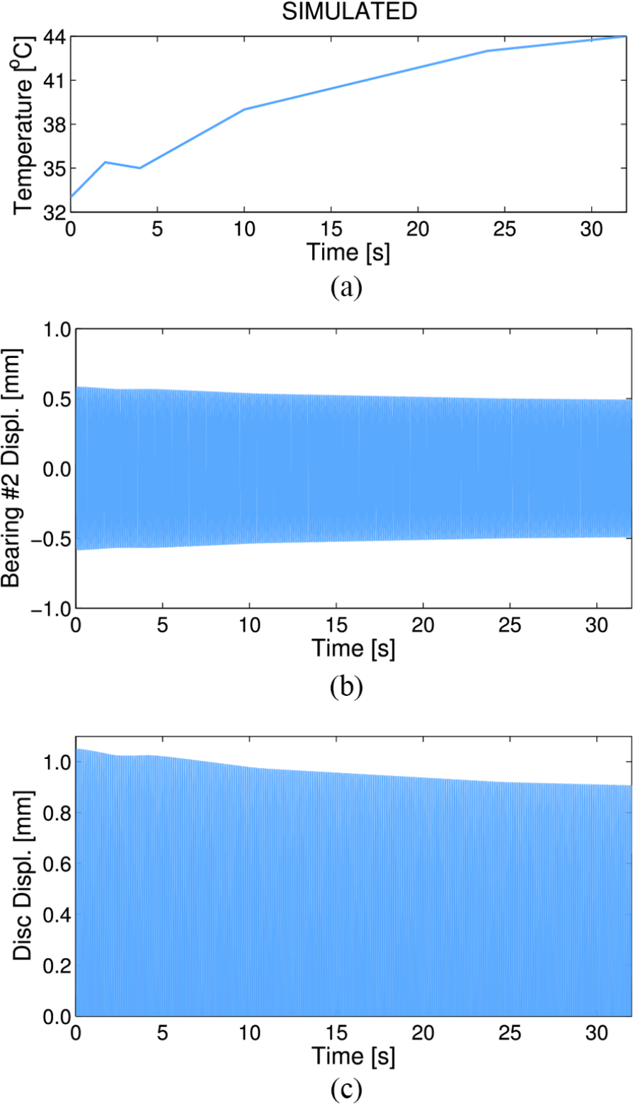
Simulated steady-state response at first critical speed and varying temperature in the SPW: (a) temperature time history, (b) bearing #2 displacement (node #16), and (c) disk displacement (node #12).
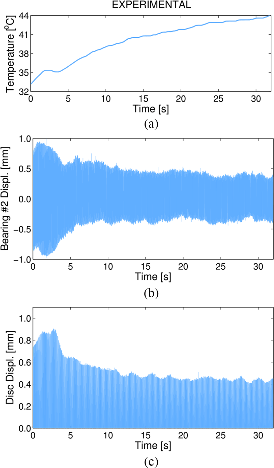
Experimental steady-state response at first critical speed and varying temperature in the SPW: (a) temperature time history, (b) bearing #2 displacement, and (c) disk displacement.
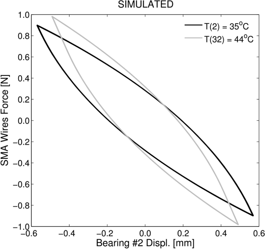
Simulated hysteresis loop at first critical speed and varying temperature in the SPW.
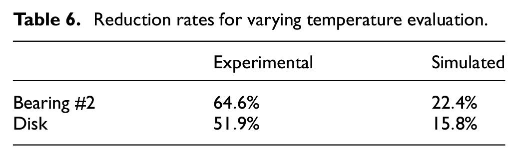
Reduction rates for varying temperature evaluation.
Transient response (run-up) for several temperatures
In this case, the unbalanced rotor was subjected to a constant acceleration of
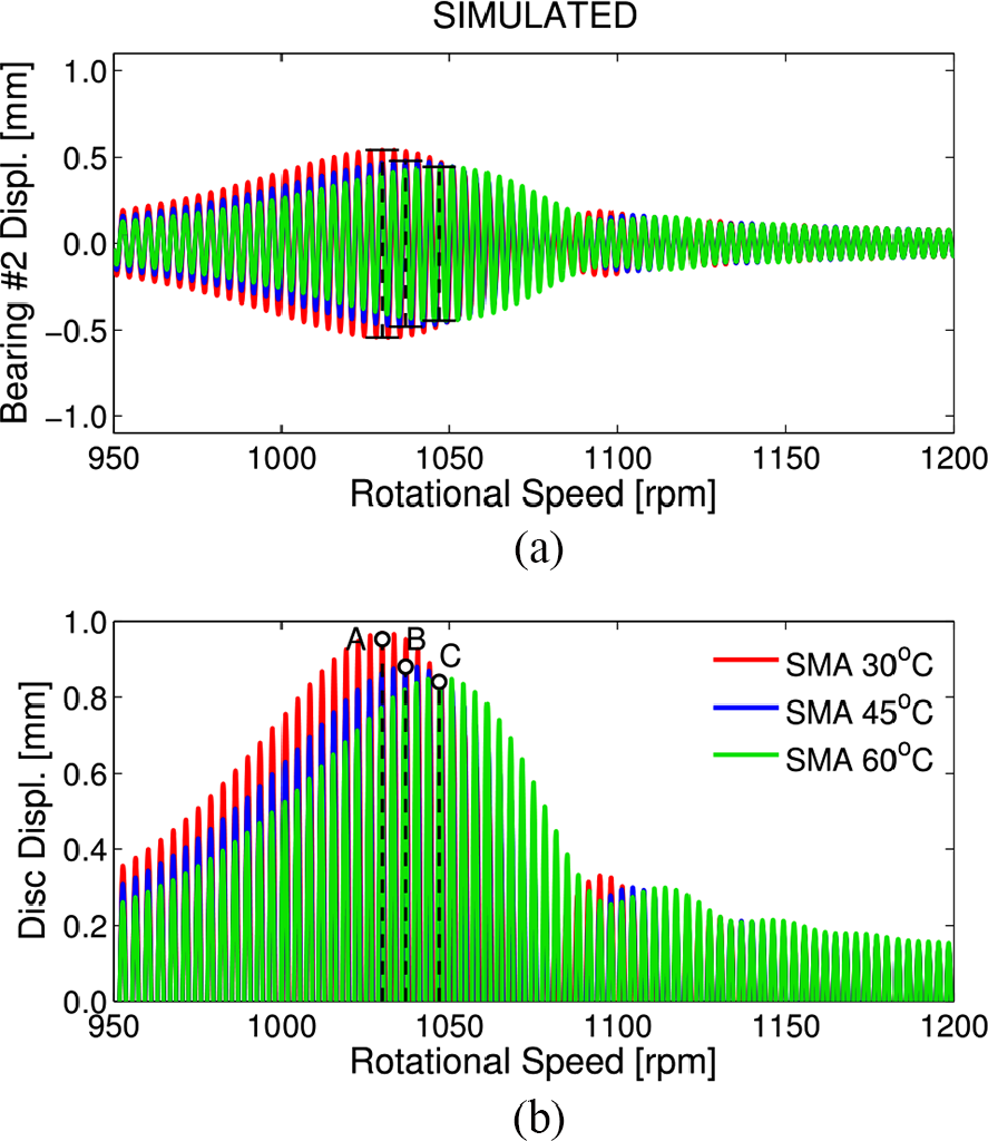
Simulated transient response: (a) bearing #2 displacement (node #16) and (b) disk displacement (node #12).
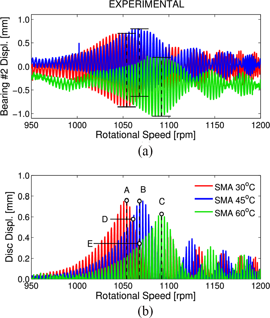
Experimental transient response: (a) bearing #2 displacement and (b) disk displacement.
Comparison between experimental and simulated results—transient response (run-up) speed for several temperatures.
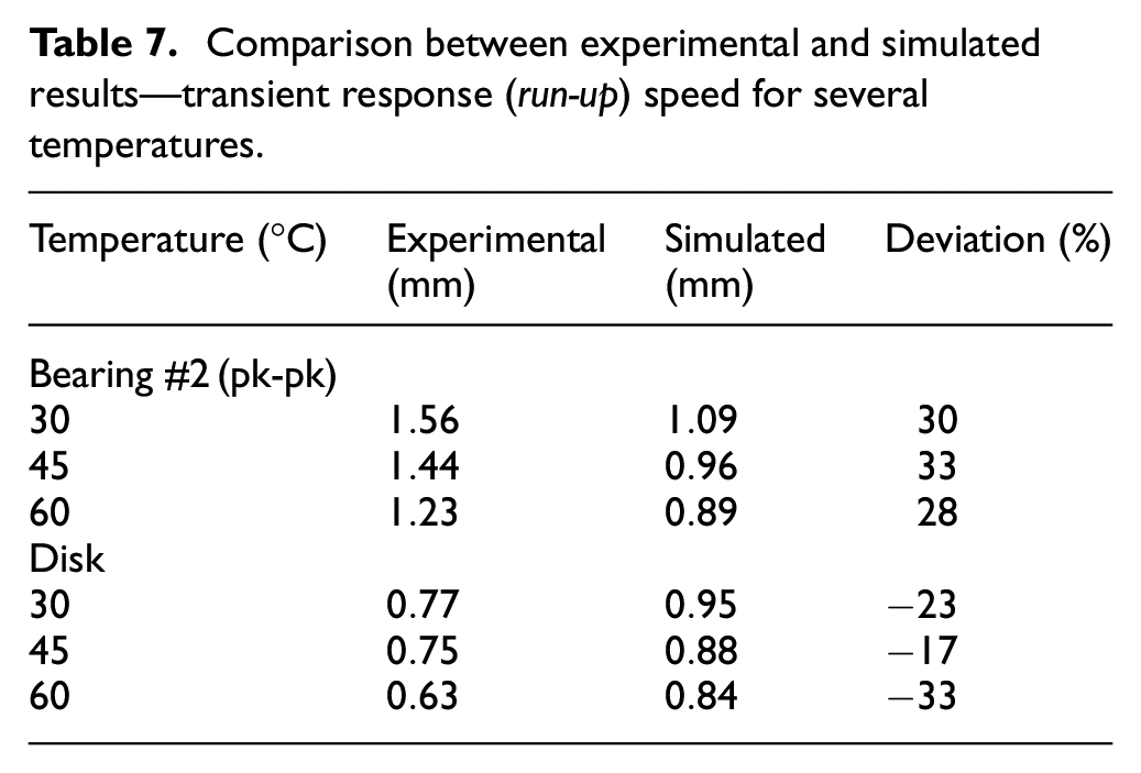
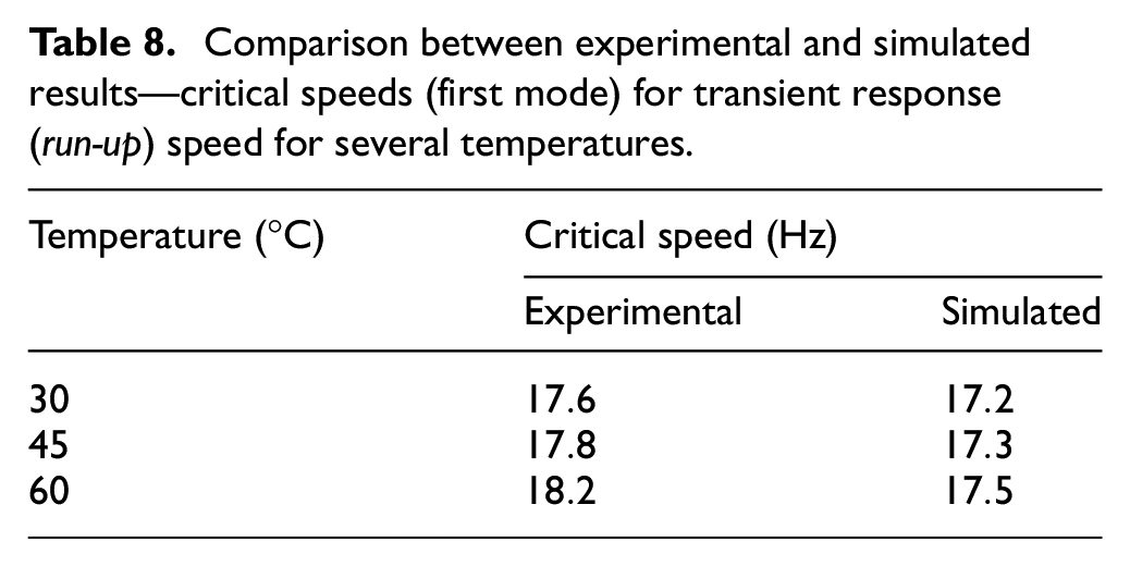
By observing the simulated and experimental responses, they do not correspond quantitatively. However, the difference found between the two cases are related to the assumptions that will be discussed later in this article. Another point is the fact that the critical speed of the rotor is temperature dependent, as commented and justified previously, where the higher the temperature, the larger the critical speed of the rotor, as can be seen in Table 8. Regarding the experimental case, two aspects were considered, as shown in Table 9. First, the focus relied on the response for each temperature; then, a potential way to cool down the wires in the suspension of the rotor was tested.
Comparison between experimental and simulated results—critical speeds (first mode) for transient response (run-up) speed for several temperatures.
Simulated and experimental reduction rates for the disk displacements.
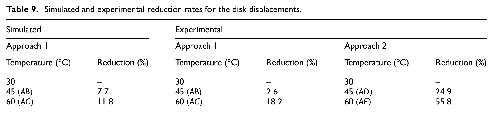
In the first experimental approach, considering the response for the temperature
Comments on the key assumptions
For all cases studied above, the performance of the suspension (SPW), as demonstrated by the experimental results, was better than the results obtained from the simulation in terms of vibration reduction. This means that the performance of the model is deeply linked to the assumptions that were made to construct the model. These assumptions are now discussed in the following:
The temperature along the wire is equal to the temperature of the environment: in real world suspensions, the heating chamber is not hermetically sealed. Besides, its geometry is not able to provide a uniform air flow distribution and, consequently, an unequal thermal field results;
Constant temperature in the wire cross-sectional area: for this reason, the diameter of wire was chosen as
Thermal expansion of SMA wire is neglected: due to thermal expansion, the (stress-free) length of the SMA wires increases with temperature. This means the pre-tension length and pre-tension force decreases with temperature. This phenomenon is neglected in the model and could therefore be a strong assumption;
Self-heating of SMA wire is neglected: whenever a cyclic mechanical loading takes place self-heating is induced, which amplifies the effect of the environmental temperature;
Thermomechanical properties of SMA wire are deterministic: actually, no matter how good the characterization process is, the parameters always carry a certain level of uncertainty.
Concluding remarks
Numerical simulations have been carried out for a rotor-bearing system suspended by pre-tensioned wires (SPW) in which pseudoelastic SMA wires are used to control the dynamic response of the system. In this sense, a modified Brinson’s model was used to describe the SMA wire behavior when subjected to thermomechanical loading. It was shown that for all tests performed, the results reveal that the higher vibration and the higher temperature, the higher damping effect will be expected from the SMA suspension. This conclusion is supported by the amplitude reduction that was observed for the rotor-bearing system.
For the impulse response with the rotor at rest, the suspension was capable of reducing slightly the amplitude since the response due to impact vanishes rapidly in such a way that the duration of the phase transformation (migration from martensite to austenite and vice versa) is extremely short. By analyzing the transient response, it was observed that the performance of the suspension was even better because in the run-up operation, and the amplitude vibration becomes larger as the rotor passes through the critical speed, thus potentializing the phase transformation and, consequently, the damping effect (energy dissipation). Besides, if the possibility of cooling the SMA suspension down after the rotor passes through the critical speed (baseline at
It was demonstrated that the dynamic behavior of the system should be evaluated according to two important parameters, namely, the hysteresis and stiffness. An important result of the present investigation is that the numerical model was capable of providing a reasonable qualitative agreement with the experimental results. For this reason, a natural topic for further research is to investigate the assumptions that were made to construct the model of the rotor-bearing system suspended by SMA wires. Anyway, the overall results showed that the SMA is efficient to reduce the vibration level of the system and can be used as an alternative solution to passive vibration control of rotating systems. Another important point is that for relatively low temperatures (in comparison with room temperature), for low heating power consumption (heating for short periods), the vibration reduction was significant.
Finally, based on the results above, it is possible to say that SMA wires represent an interesting alternative for semi-active rotor vibration control. In addition, the use of SMA in this context complies with the requirement of low energy consumption, as expected for the so-called eco-rotors.
Footnotes
Declaration of conflicting interests
The author(s) declared no potential conflicts of interest with respect to the research, authorship, and/or publication of this article.
Funding
The author(s) disclosed receipt of the following financial support for the research, authorship, and/or publication of this article: The authors are thankful to Brazilian Research Agencies such as CNPq and CAPES (supported by process BEX 11550/12-0) and to the Technical University of Denmark (supported by FTP research project 12-127502). The authors are also thankful to CNPq and FAPEMIG Brazilian Research Agencies for their support through INCT-EIE.