
Abstract
The optimal placement and active vibration control for piezoelectric smart single flexible manipulator are investigated in this study. Based on the assumed mode method and Hamilton’s principle, the dynamic equation of the piezoelectric smart single flexible manipulator is established. Then, the singular perturbation method is adopted and the coupled dynamic equation is decomposed into slow (rigid) and fast (flexible) subsystems. After that, the couple optimal placement criterion of piezoelectric actuators is proposed on the base of modal H2 norm of the fast subsystem and the change rate of natural frequencies. Using an improved particle swarm optimization algorithm, the optimal placement of piezoelectric actuators is realized. Subsequently, in order to verify the validity and feasibility of the presented optimal placement criterion, the composite controller is designed for the active vibration control of the piezoelectric smart single flexible manipulator. Finally, numerical simulations and experiments are presented. The results demonstrate that the piezoelectric smart single flexible manipulator system has a better single modal controllability and observability and has a good result on the vibration suppression using the optimization results of actuators. The proposed optimal placement criterion and method are feasible and effective.
Introduction
Flexible manipulators have been actively used in various fields, such as aerospace, industry, and medical treatment (Zi et al., 2017). It remains that the tip of the flexible manipulator should accurately trail the target trajectory without vibration (Liu et al., 2015; Qian et al., 2016). Due to their low stiffness and low damping characteristics, the elastic vibration of flexible manipulators is easily aroused in the process of moving. The resulting elastic vibration has obvious influence on the dynamic precision of the equipment (Liu et al., 2013). As a result, the elastic vibration of flexible manipulators can no longer be ignored. Smart piezoelectric materials, especially the piezoelectric ceramic has a superior characteristic of dual functions of actuating and sensing with excellent mechanical–electrical coupling characteristics which are widely used in the study of active vibration control of flexible manipulators (Li et al., 2012). At present, the research on vibration control which contains establishment of mathematics model, control algorithm, and optimal placement of actuators/sensors has aroused wide attention of many scholars (Cao and Yu, 2010; Jnifene, 2007).
The optimal placement of piezoelectric actuators determines the controllability, observability, stability, and effectiveness of the active vibration control system (Hasheminejad and Oveisi, 2016), and inappropriate placement can greatly deteriorate the performance of the systems and even drive the systems to be unstable. Therefore, the optimal placement of piezoelectric actuators is an important problem worthy of study in active vibration control of smart flexible structures. Many researchers have done a lot of related research. Barboni et al. (2000) considered a beam vibration problem where the objective was to maximize the displacement generated by a pair of actuators. Qiu et al. (2007) developed an optimal placement method of piezoelectric actuators/sensors for cantilever plate based on the maximization of observability and controllability indexes. Yang et al. (2005) studied optimal design of vibration control system for smart beams based on the biggest energy consumption index. Lou et al. (2016) proposed that a synthetic modal H2 norm criterion represents the controllability and observability and designed an experimental to verify the feasibility of optimal method. Sun et al. (2004) investigated the use of PZT (lead zirconate titanate) actuators for suppressing vibration of a single-link flexible manipulator by a combined scheme of PD feedback, the positions of actuators were examined based on the analysis of modal forces. Using the of mode shape functions, the optimal placement of piezoelectric actuators for vibration control of two-link flexible manipulator was studied by Cao and Yu (2010). The optimal placement and size of the piezoelectric actuators/sensors in vibration control of flexible manipulators were optimized through the maximizing energy dissipated by Bottega et al. (2009).
From these reviews of literature, it can be found that the researches on optimal placement of piezoelectric sensors or actuators mainly focused on the modal forces, maximizing energy dissipated and maximizing degree of observability or controllability. In order to ensure maximum control and measurement effectiveness in the active vibration control of flexible manipulators, the positions of actuators or sensors should be optimized to obtain the required values of the controllability and observability Gramian matrices (Qiu et al., 2007). However, compared with the flexible beams or plates, the elastic deformations of flexible manipulators couple with the rigid motions of rigid bodies. It is difficult to be optimized using conventional methods which are applied in the flexible beams or plates. Therefore, in implementing the optimization of piezoelectric actuators for flexible manipulators, a new train of thought needs to be put forward. The singular perturbation theory has been shown to be a convenient strategy for “reduced-order modeling” in recent years (Jia et al., 2013; Lin and Lewis, 2003). Based on the singular perturbation theory, the highly nonlinear and strongly coupled dynamic equation of flexible manipulators can be decomposed into a slow subsystem corresponding to the rigid body and a fast subsystem describing the flexible motion (Yang and Ge, 2014). The fast subsystem is closely related to the effect of vibration suppression and it is similar to the smart beam system. Hence, the optimal placement of piezoelectric actuators can be performed in a fast subsystem system.
This article aims to investigate the optimal placement of piezoelectric actuators for flexible manipulators and to help achieve the active vibration control of piezoelectric smart flexible manipulators. The article is organized as follows. The mathematical modeling of the piezoelectric smart single flexible manipulator (SFM) is stated in section “Mathematical modeling.” In section “Optimal placement of the piezoelectric actuators,” the optimal placement method of piezoelectric actuators for piezoelectric smart SFM is presented according to maximum observability and controllability rule using modal H2 norm and the change rate of natural frequencies. Subsequently, to verify the optimization results, the design of the active vibration controller is given in section “Design of the composite controller.” In section “Simulations and experiments,” numerical simulations and experiments of the optimal placement and active vibration control of the piezoelectric smart SFM are carried out. Finally, the article is concluded with a brief summary in section “Conclusion.”
Mathematical modeling
Dynamic model of the piezoelectric smart SFM
The structural diagram of the piezoelectric smart SFM in the horizontal plane studied in this article is shown in Figure 1. In the figure, the coordinates XOY and xoy indicate the inertial frame and the reference frame, respectively. And, τ(t) is the output torque of the speed reducer which is driven by a motor, Jh is the rotational inertia of the hub (motor shaft and fixture), r is the radius of the hub, θ(t) is the angular displacement of the hub, and mL is the tip mass of the SFM. Besides, Eb, ρb, Lb, bb, and hb denote the elastic modulus, density, length, width of cross section, and height of cross section of the SFM, respectively. Ep, ρp, Lp, bp, and hp denote the elastic modulus, density, length, width of cross section, and height of cross section of the actuators, respectively.
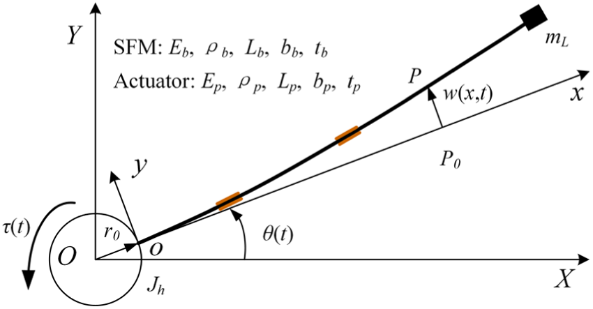
Structural diagram of the piezoelectric smart SFM.
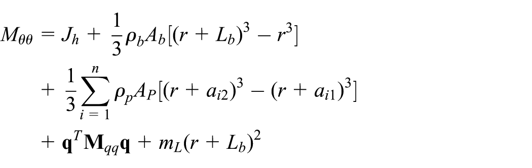
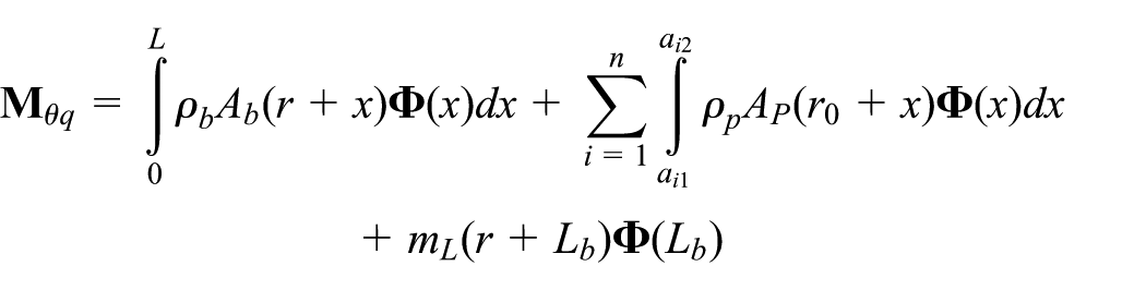
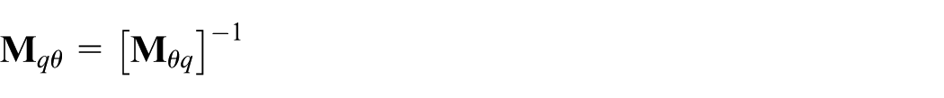
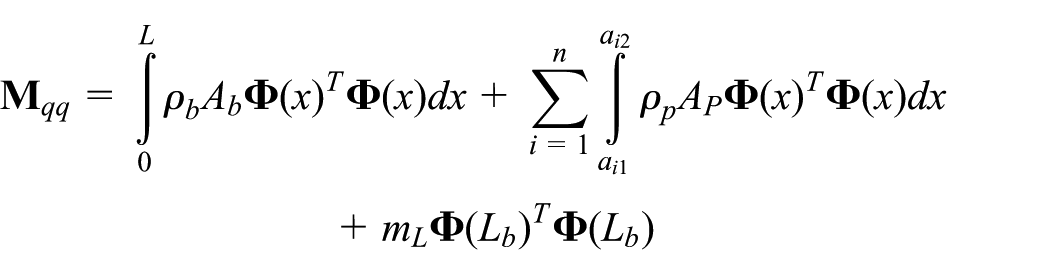
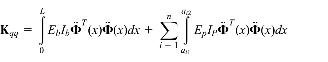
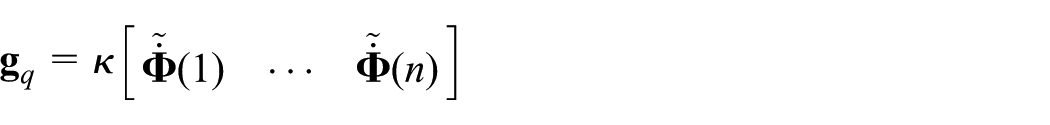
In accordance with the assumed mode method and Hamilton’s principle, the dynamic equation of the piezoelectric smart SFM at the element level in compact form can be written as follows (Lu et al., 2016)
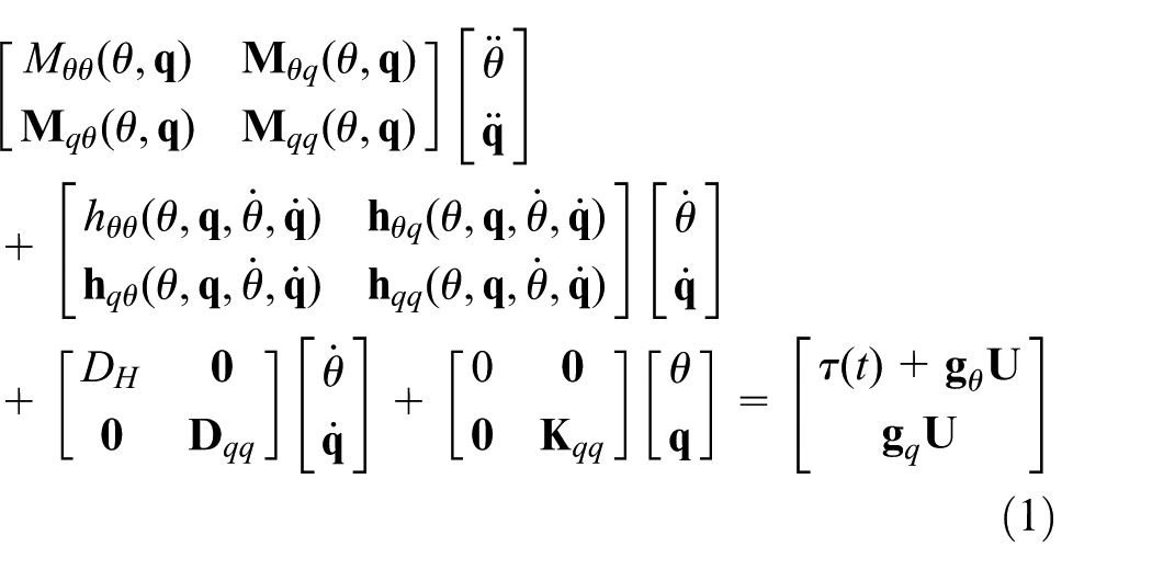
where


Singular perturbation decomposition of dynamic equation
Since the inertia matrix in equation (1) is positive definite, it can be inverted and can be written as the following form (Jia et al., 2013)
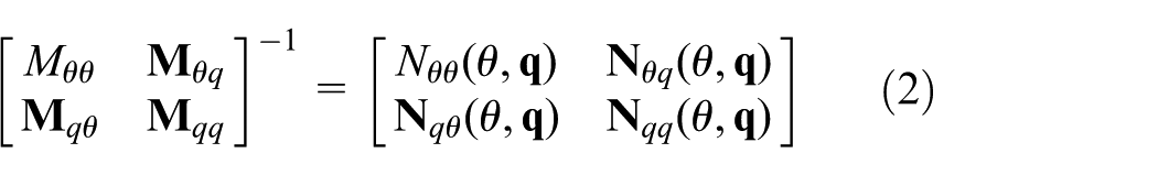
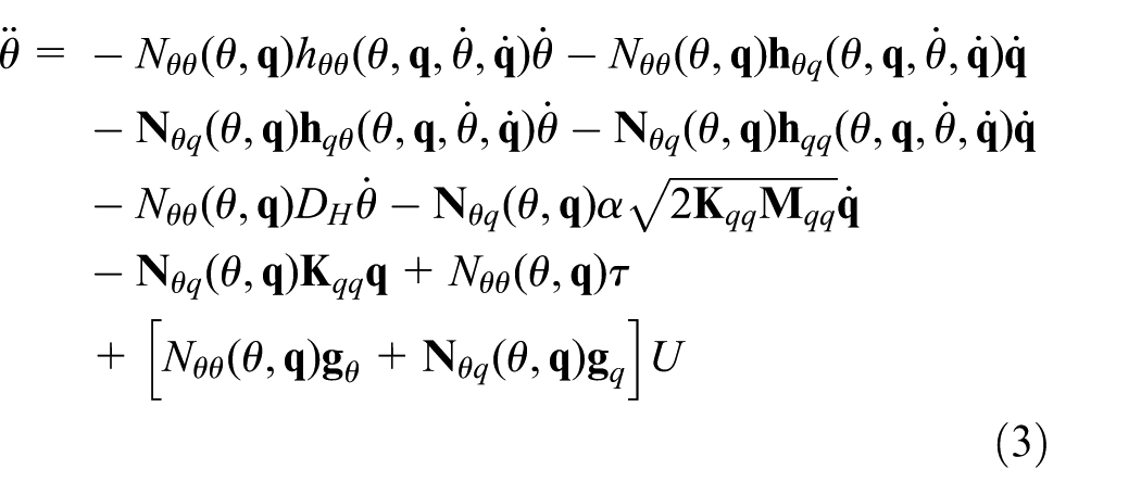
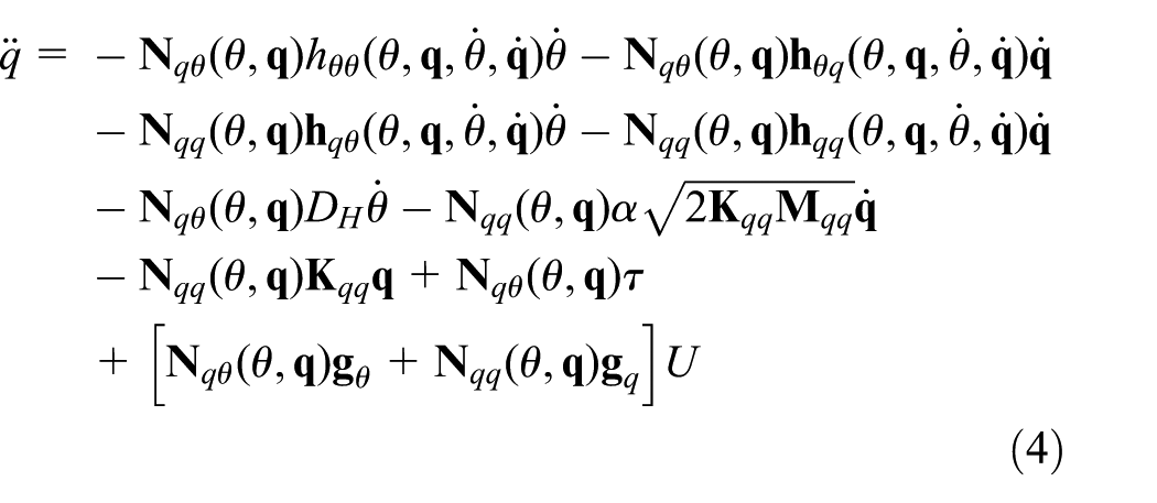
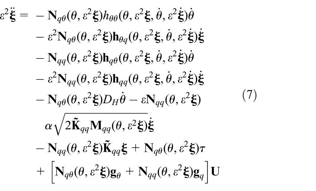
Therefore, equation (1) can be rewritten as follows
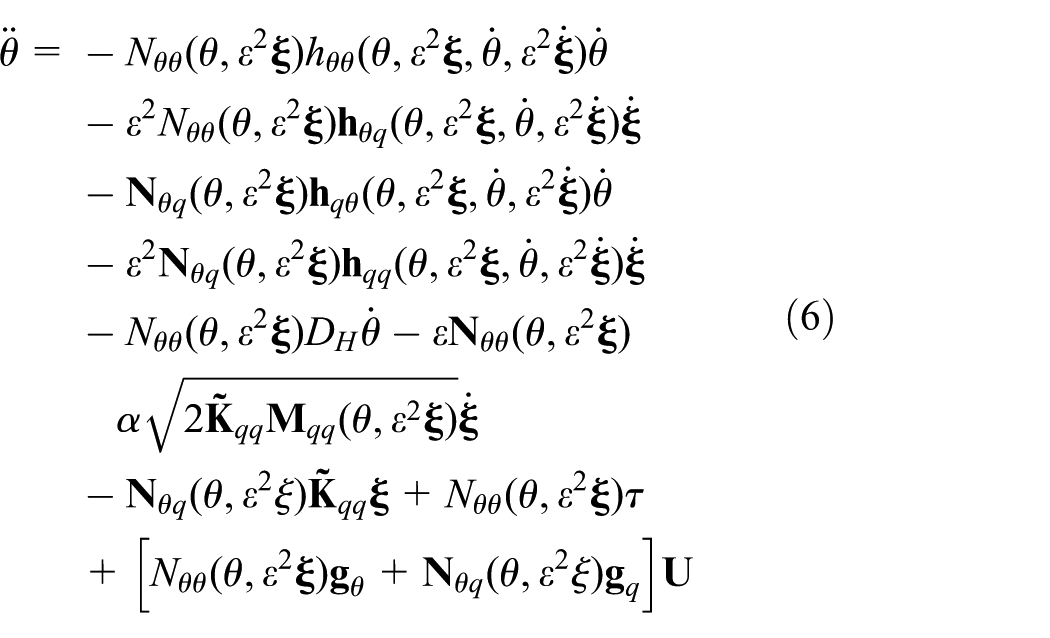
Assuming that kc is the smallest element of the matrix

Equation (5) is substituted into equations (3) and (4); the dynamics equation of the piezoelectric smart SFM can be represented in singular perturbation form as follows
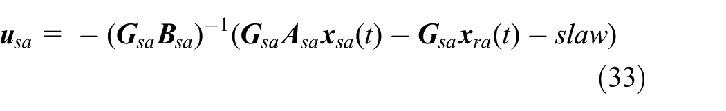
Slow subsystem
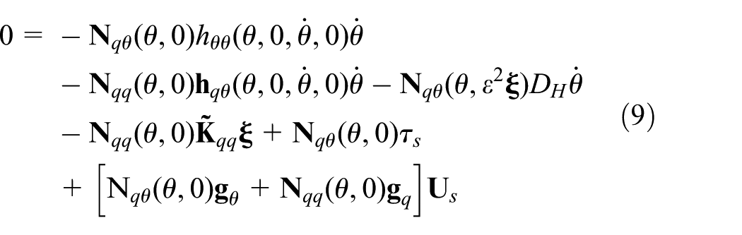
To derive the boundary layer correction, ε is set to 0 and the model of the rigid manipulator is expressed as follows
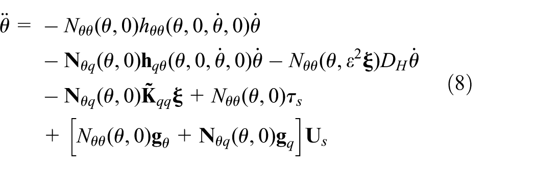
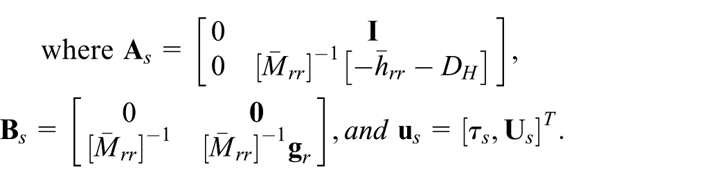
Combining equations (2), (8), and (9), the slow time scale subsystem is given as follows
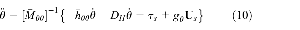
where τs is the control torque of slow time scale subsystem,
Let

Fast subsystem
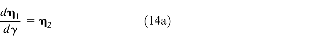
To derive the fast subsystem, introduce a fast time scale

Then, equation (7) is rewritten as follows
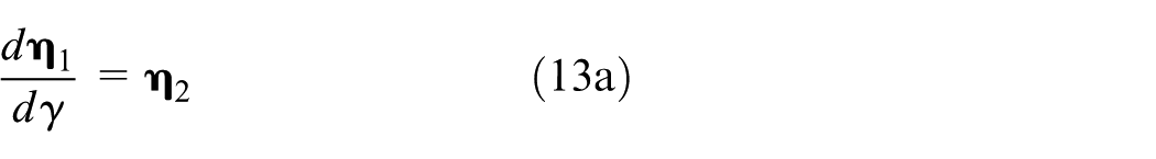
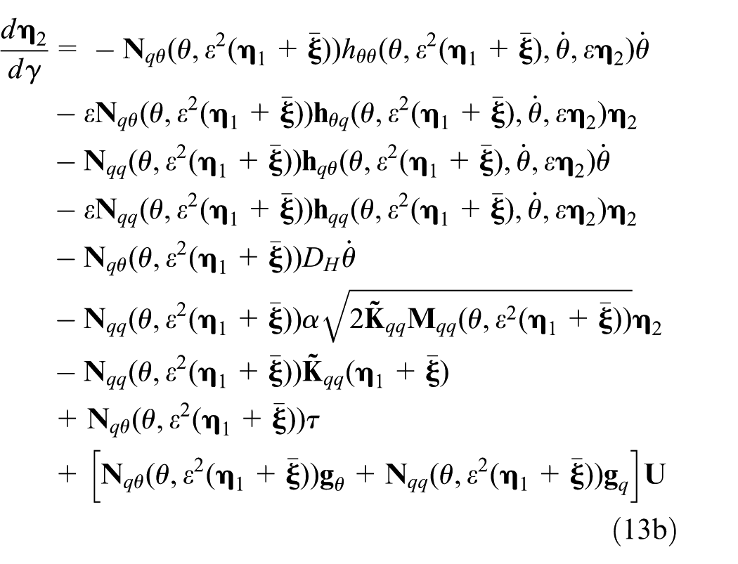
Because the slow time scale and fast time scale are independent of each other, near boundary layer region ε→0, the slow varying component can be regarded as constant
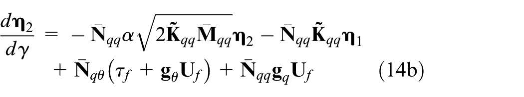
where τf is the control torque of fast time scale subsystem, Uf is the control voltage of fast time scale subsystem.
Defining boundary layer variables as

where
Optimal placement of the piezoelectric actuators
In section “Mathematical modeling,” based on the singular perturbation theory, the highly nonlinear and strongly coupled dynamic equation of piezoelectric smart SFM is decomposed into a slow subsystem corresponding to the rigid body and a fast subsystem describing the flexible motion, as shown in Figure 2. The elastic vibration of piezoelectric smart SFM mainly comes from the flexible motion which is described by the fast subsystem. Therefore, the optimal placement of the piezoelectric actuators is executed in this section based on the fast subsystem.
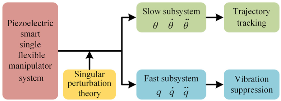
Structural diagram of singular perturbation decomposition of dynamic equation.
Optimal placement criterion for piezoelectric actuators
It has been found that the input and output matrices of a system contain the information on the system controllability and observability. The H2 norms of the input and output matrices in modal coordinates contain information on the structural controllability and observability and are called input and output gains, respectively (Gawronski, 2004). In the following, the controllability and observability property indexes are established by the modal H2 norm.
First, the output equation of the fast subsystem is defined as follows

where
Combining equations (15) and (16), the state equation of the fast subsystem is as follows
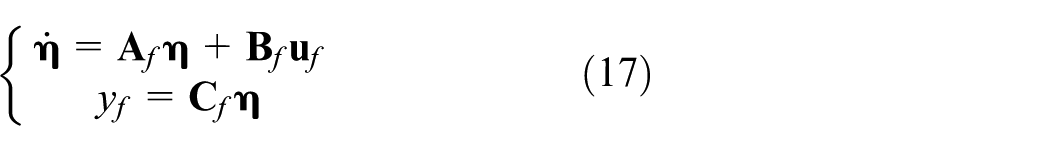
Equation (17) is written as transfer function and shown as follows

The spatial H2 norm for the transfer function
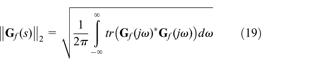
where
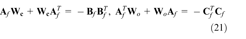
Equation (18) is substituted into equation (19) and the optimum simplified expression is shown as follows (Liu et al., 2006)
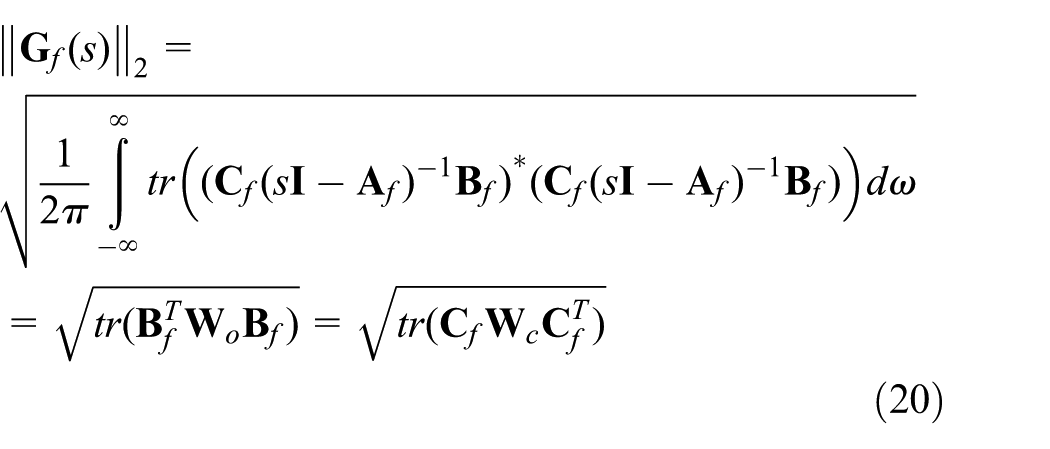
where
Due to the state–space equation is adopted by the modal theory and modal truncation technique, when the modal damping ratio of the system structure is smaller than 1, the spatial H2 norm of the ith mode can be represented as the following form (Qiu et al., 2007)
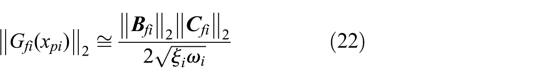
where xpi is the position of the ith actuator,
For the piezoelectric smart SFM with n-order vibration modes, a couple placement modal index is defined as follows (Lou et al., 2016)
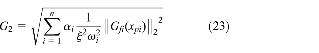
where αi is the weighting coefficient.
Compared with the SFM, the size of piezoelectric actuators is relatively small and the influence of structural characteristics is often ignored in the study of the vibration control of the piezoelectric smart SFM. However, the piezoelectric actuators pasted on the SFM will inevitably lead to the change of the structural characteristics. The SFM faces the development trend of lightweight and flexibility, the influence of piezoelectric actuators cannot be ignored, and the change of natural frequencies should be controlled in a reasonable range. Considering the influence of piezoelectric actuators for structure, the evaluation index is proposed and shown as follows
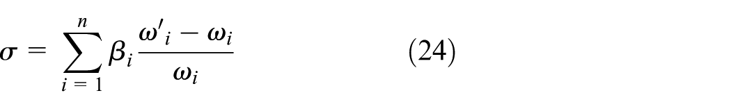
where σ is the rate of change of the total natural frequencies, ωi is the ith natural frequency of the SFM,
Finally, the couple optimal placement criterion is
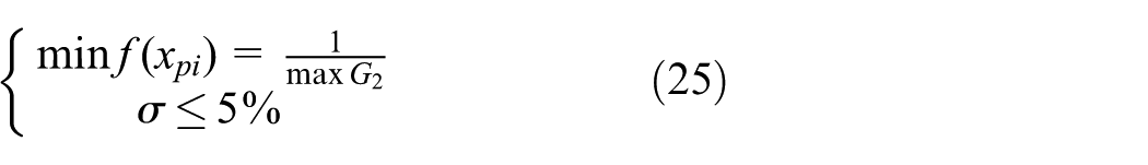
Subject to: 0 ≤xpi≤Lb−Lp, ‖xpi+1−xpi‖≥Lp.
Solution methodology
Particle swarm optimization (PSO) algorithm is based on the social behavior of a flock of birds. In this algorithm, a swarm of particles is represented as potential solutions. Assuming that the dimension of each particle is D, the position and velocity of ith particle are expressed as
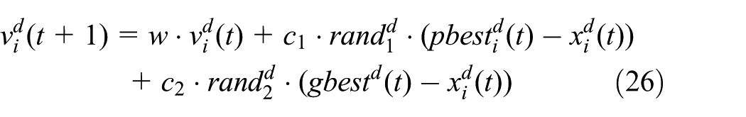

where w is the inertia weight, c1 and c2 are the acceleration parameters, respectively;
Crossover operation is one of the three basic genetic operators used in genetic algorithm (Li et al., 2017), which plays a very important role in improving the quality of the solution population. This article adds crossover operation to original PSO and increases the diversity of information. Add the following crossover operation after the velocity update (Giovanni et al., 2017; Martínez-Soto et al., 2014)

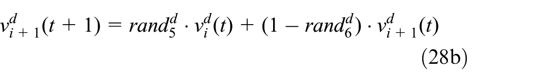
In the hybrid particle swarm optimization (HPSO), the new particle is refreshed by crossover operation and the velocity particles take the place of the new particles. The offspring particles often inherit the advantages of each parent particles after crossover operation, and the searching between the particles is enhanced. For example, when both parent particles in a different area of the local optimum, the offspring particles can resolve the problems of local optimal and improve the search results. The general framework illustrating the above procedure is shown in Figure 3.
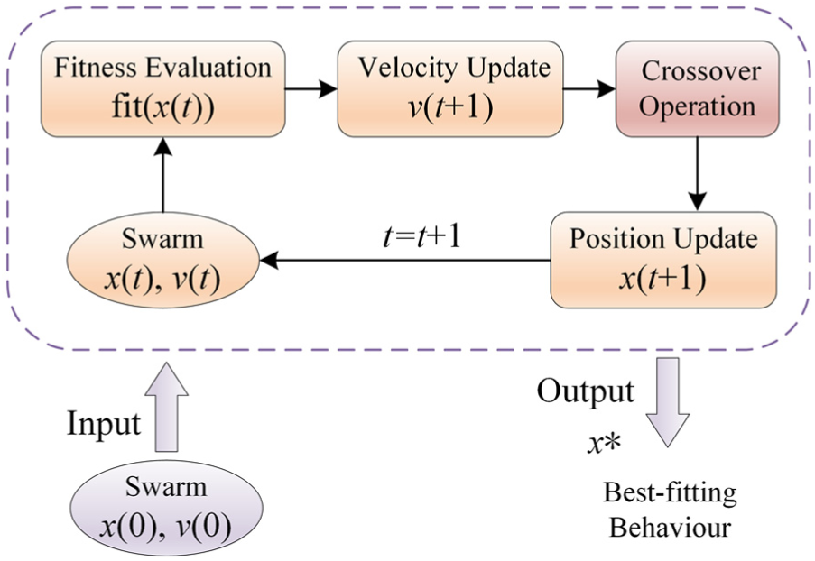
Main components of the HPSO.
Optimization results
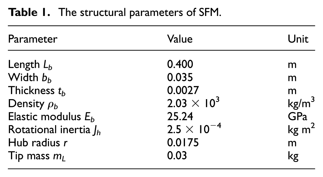
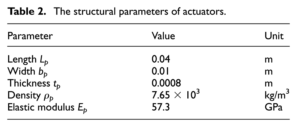
Owing to the lower order modes play leading role in the vibration of the piezoelectric smart SFM, only the first two order modes are considered and the structural parameters of the SFM and actuators are shown in Tables 1 and 2, respectively.
The structural parameters of SFM.
The structural parameters of actuators.
In the process of optimization solution, the population size is 40, the maximum evolution number is 50, the probability of crossover operation is 0.6, the inertia weight w is 0.729, and the acceleration parameters c1, c2 are 1.494, 1.494, respectively. The optimization results of piezoelectric actuators are shown in Figure 4. From Figure 4(a), the HPSO algorithm can converge to optimization solution after about 12 generation evolution. The first pair of piezoelectric actuators should be bonded in the position of x = 43.37 mm and the second pair of piezoelectric actuators should be bonded in the position of x = 192.5 mm, as shown in Figure 4(b).
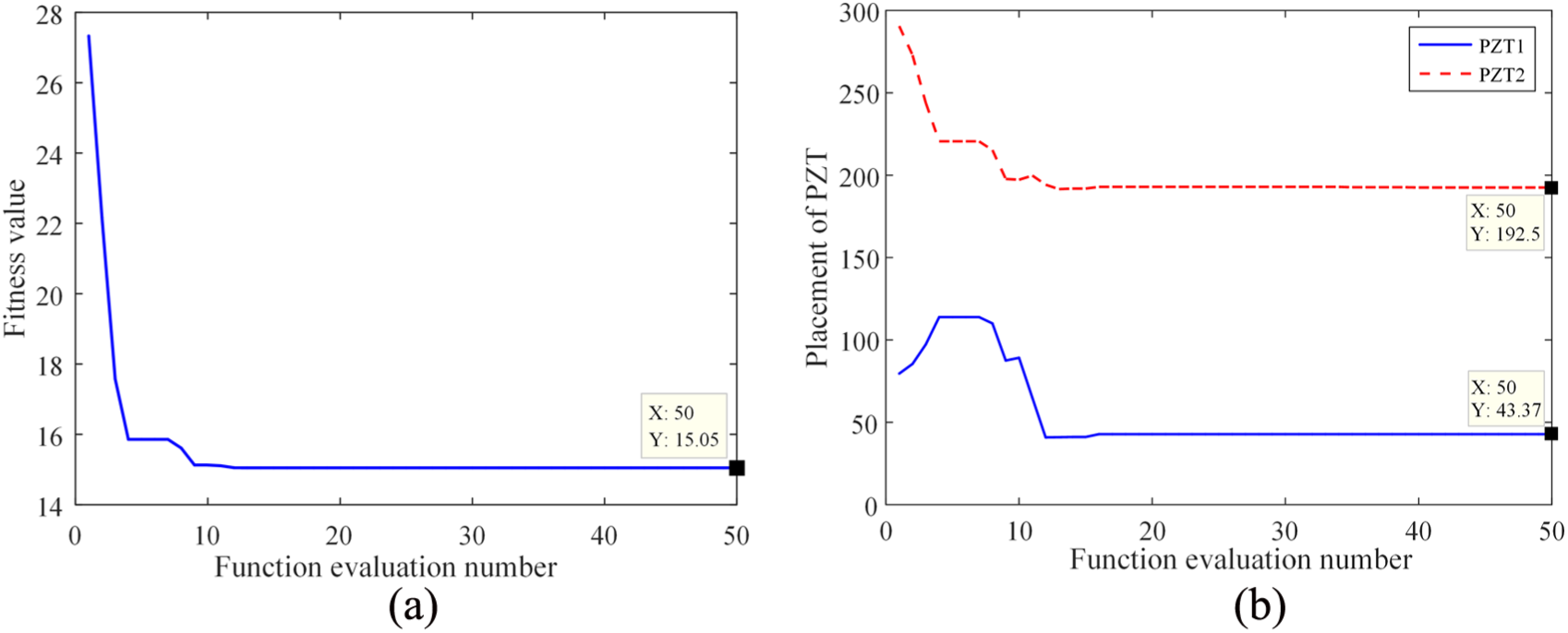
Optimization results of piezoelectric actuators: (a) convergence chart of fitness values and (b) optimization curves of piezoelectric actuators.
Design of the composite controller
To verify the optimization results of the piezoelectric actuator bases on modal H2 norm, the active vibration control of piezoelectric smart SFM is conducted in this section.
Design of slow subsystem controller
The slow time scale subsystem equation (11) is augmented as follows (Sun et al., 2015)

where
Assuming the desired trajectory as

Define a sliding surface

Taking the derivative of the sliding surface

Combining equations (29) and (32), the control law of slow time scale subsystem is expressed as follows
The reaching law function is shown as follows

In order to reduce the chatter phenomenon of sliding mode control (SMC), the sign function sgn(
Design of fast subsystem controller
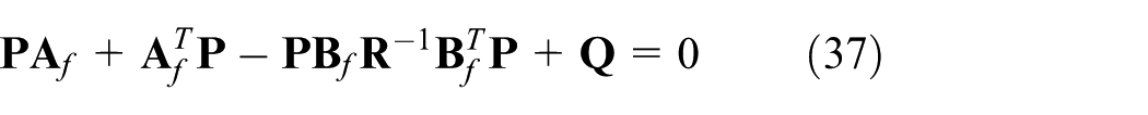
To damp out the flexible vibration and decrease the control effort, the simple performance index is chosen as follows
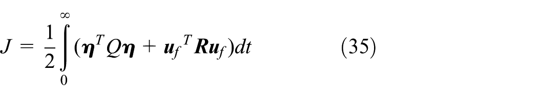
where
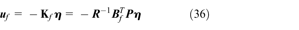
where
Simulations and experiments
Numerical simulations
The angular displacement trajectory of the smart SFM is shown as follows
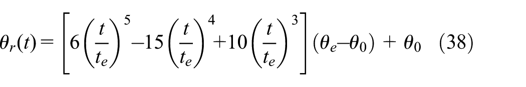
where θr is the terminal angular displacement, θe is the initial angle, and te is the finish time.
The simulation curves of active vibration control of the piezoelectric smart SFM are shown in Figure 5. Figure 5(a) shows the output control torque of the speed reducer which is driven by a motor. Figure 5(b) shows the control voltage of actuators. Figure 5(c) shows the tip angle of the piezoelectric smart SFM and it demonstrates that the composite controller successfully implements the motion trajectory control and vibration suppression of the SFM. Figure 5(d) shows the structural strain history along the length of the piezoelectric smart SFM for the first 3 s of the smart SFM motion. It can be observed that the highest strain experienced occurs in the root of the smart SFM and the strain is reduced gradually in the control of composite controller. Meanwhile, it is evident that the optimal placement of actuators is feasible based on the modal H2 norm and the change rate of natural frequencies. The first-order modal coordinate and second-order modal coordinate are shown in Figure 5(e) and (f), respectively. It is obtained that the single modal of piezoelectric smart SFM system has a high degree of controllability and observability and the proposed optimal placement criterion and method are feasible and effective. Moreover, the first-order modal coordinate is much larger than the second-order modal coordinate and illustrates that the lower order modes play leading role in the vibration of the smart SFM. Figure 5(g) shows the tip deflection in movement of the SFM, and the proposed method can successfully suppress the elastic vibration.
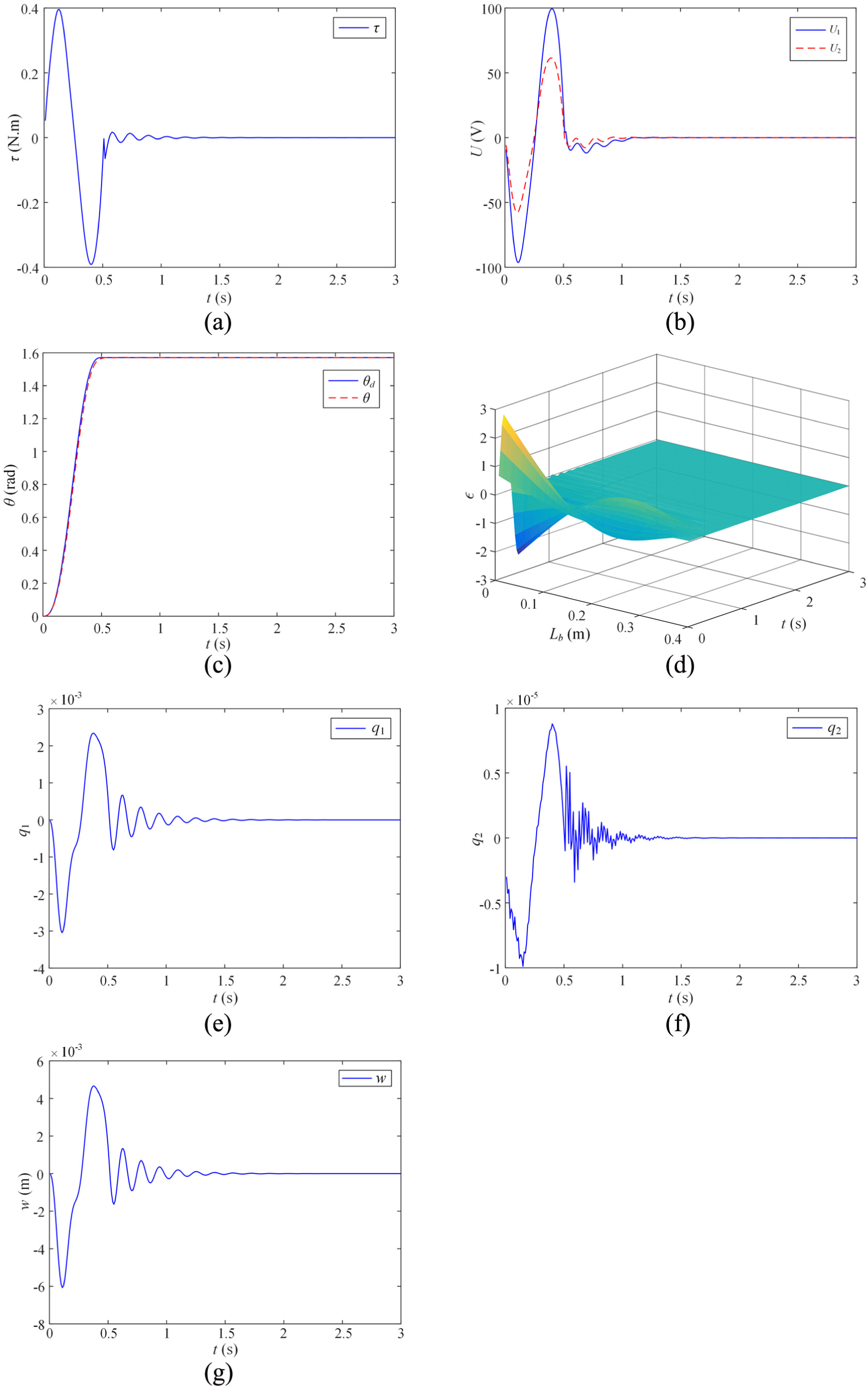
Simulation curves of active vibration control of the piezoelectric smart SFM: (a) control torque, (b) control voltage, (c) tip angle, (d) strain time history, (e) first-order modal coordinate, (f) second-order modal coordinate, and (g) tip deflection.
Control experiments
In order to better demonstrate the effectiveness of the optimal placement and active vibration control for the piezoelectric smart SFM, the experiments on control of the SFM are constructed. The overall experimental apparatus and the flow chart of optimal placement and control experiments are depicted in Figures 6 and 7, respectively.
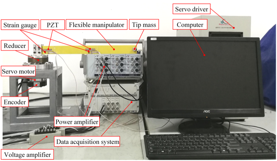
Photograph of the experimental apparatus.
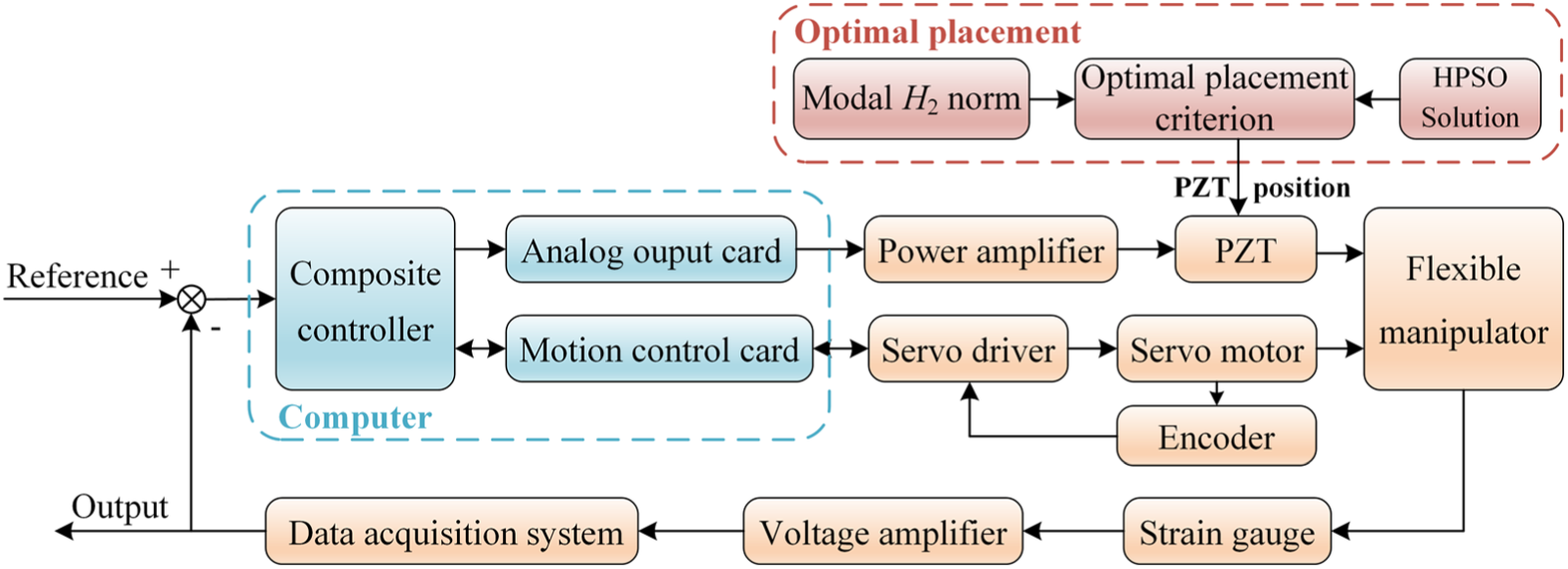
Flow chart of the optimal placement and control experiments.
The comparison between the simulated and experimental results is shown in Figure 8. Figure 8(a) and (b) shows the the control torque of the speed reducer which is driven by a motor and the control voltage of actuators, respectively. Figure 8(c) shows the tip angle of the piezoelectric smart SFM, and the effectiveness of optimal placement and active vibration control methods for the SFM is illustrated. Meanwhile, it is evident from Figure 8(d) that the proposed method can successfully suppress the elastic vibration of the SFM in the process of moving.
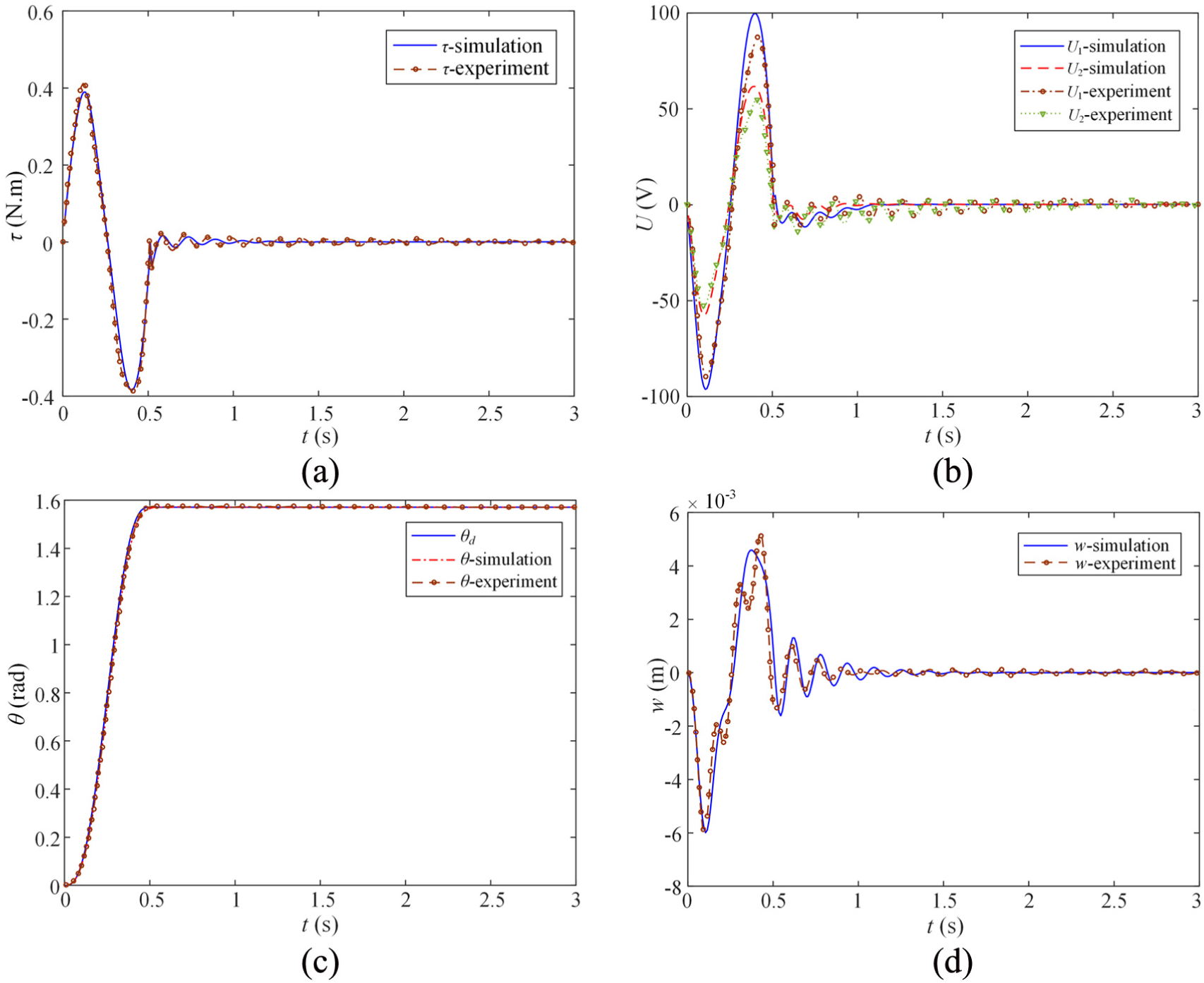
Comparison between the simulated and experimental results: (a) control torque, (b) control voltage, (c) tip angle, and (d) tip deflection.
Conclusion
This article mainly discusses the optimal placement of piezoelectric actuators and active vibration control for the piezoelectric smart SFM. The dynamic equation of the piezoelectric smart SFM is described by means of the assumed mode method and Hamilton’s principle. Based on the singular perturbation method, the coupled dynamic equation is decomposed into slow (rigid) and fast (flexible) subsystems. Then, the couple optimal placement criterion is produced based on the modal H2 norm of the fast subsystem and the change rate of natural frequencies. Subsequently, the proposed placement criterion is solved by the HPSO algorithm. After that, the composite controller of the piezoelectric smart SFM is designed using the SMC and linear quadratic regulator (LQR) method.
By the analysis of numerical simulations, it can be found that the composite controller can successfully suppress the elastic vibration in movement of the smart SFM, and the closed-loop stability of the piezoelectric smart SFM is achieved. Moreover, the simulation curves of the modal coordinates illustrate that the single modal has better controllability and observability. Meanwhile, the experimental results are consistent with simulation results and the active vibration control effect of the composite controller reaches the expectation. All the results above prove that the proposed optimal placement criterion and method are feasible and effective. The modal H2 norm and change rate of natural frequencies are introduced into the optimal placement of the smart SFM by the singular perturbation method, which has provided reference for other researchers.
Footnotes
Declaration of conflicting interests
The author(s) declared no potential conflicts of interest with respect to the research, authorship, and/or publication of this article.
Funding
The author(s) disclosed receipt of the following financial support for the research, authorship, and/or publication of this article: This research work was partially supported by the National Natural Science Foundation of China (no. U1610111) and the project funded by the Priority Academic Program Development of Jiangsu Higher Education Institutions (PAPD).