






Abstract
This article addresses piezoelectric shunt damping through a resonant shunt associated with negative capacitances. The main objective of this article is to provide guidelines for choosing the best electrical circuit layout in terms of control performance and possible stability issues. This article proposes general analytical formulations for the tuning/optimisation of the electrical shunt impedance and for the prediction of the attenuation performance. These formulations are demonstrated to be valid for all the possible configurations of the negative capacitances. It is demonstrated that the behaviour of the different shunt circuits can indeed be described by a common mathematical treatment. Moreover, the use of two negative capacitances together is shown to provide benefits compared to traditional layouts based on a single negative capacitance. The mentioned advantages relate to both stability and attenuation performance. The use of a resonant shunt with the addition of negative capacitances is finally proven to provide enough attenuation to even cancel eigenfrequency peaks in some cases. This article also analyses the main issues arising from the practical implementation of the negative capacitances. Finally, the theoretical results are validated through experiments conducted on a cantilever beam coupled to two piezoelectric patches.
Introduction
Piezoelectric shunt is a well-known technique for vibration damping. This approach relies on the electrical link between a piezoelectric actuator, bonded to a vibrating structure, and a properly designed electrical network (Hagood and Von Flotow, 1991). The most used shunt impedances for single-mode control are a simple resistance (resistive shunt or R-shunt) and the series of a resistance and an inductance (resonant shunt or LR-shunt; Hagood and Von Flotow, 1991; Thomas et al., 2012; Yamada et al., 2010).
Thomas et al. (2009, 2012) and Ducarne et al. (2012) demonstrated that as soon as the electric impedance is optimally tuned, the performance of the control depends only on the modal electromechanical coupling factor (MEMCF) of each mode of the electromechanical system (EMS; composed of the vibrating structure, the piezoelectric actuator and the shunt impedance). The MEMCF is a feature of the EMS, and it is a function of the mechanical, geometrical, and electrical characteristics of the structure and the piezoelectric actuator. The MEMCF of a given mode is proven to also be related to the distance between the natural frequencies of the EMS in short circuit (SC) and open circuit (OC) of the mode considered. The higher the MEMCF is, the higher the maximum achievable attenuation is (Thomas et al., 2012).
The use of synthetic circuits can improve the attenuation performance provided by the optimally tuned shunt (e.g. Date et al., 2000; Sluka and Mokry, 2007; Tang and Wang, 2001). Among these circuits, the use of negative capacitances (NCs) has been shown to be highly reliable and effective in enhancing the performance of piezoelectric shunt damping. NCs do not exist in nature, but they can be implemented by using operational amplifiers (OP-AMPs) (Horowitz and Hill, 1989). NCs were fruitfully employed coupled to a resistive shunt (Beck et al., 2013, 2014; Behrens et al., 2003; Berardengo et al., 2016b, 2017; Collet et al., 2011; De Marneffe and Preumont, 2008; Kodejška et al., 2012; Manzoni et al., 2012; Park and Baz, 2005) and to a resonant shunt (De Marneffe and Preumont, 2008; Heuss et al., 2016; Neubauer et al., 2006). The resonant shunt coupled to NCs was proven to be highly effective in reducing the vibration level when single-mode control is needed. Furthermore, its attenuation performance is higher than that of the resistive shunt coupled to NCs. For this reason, the study of this shunt circuit deserves attention from the scientific community.
This article specifically addresses the coupling between NCs and a resonant shunt; thus, it is worth explaining the main content of the referenced works related to this type of damping approach. De Marneffe and Preumont (2008) analysed the damping performance provided by this type of shunt compared to other approaches; among them, active control was also considered. The coupling between a resonant shunt and NCs resulted in among the best solutions for the attenuation of vibrations, showing very good performance. Neubauer et al. (2006) proposed optimisation criteria for a shunt composed of a series connection of an NC, a resistance and an inductance. Heuss et al. (2016) used the connection of an NC and a resonant shunt to develop a vibration absorber composed of a beam and a piezoelectric patch connected to the mentioned shunt impedance.
However, there are still many open issues regarding the coupling between NCs and resonant shunts. The aim of this article is to address these open issues by exploiting a mathematical approach that has already been successfully used by the authors to describe the coupling between NCs and resistive shunts (Berardengo et al., 2015b, 2016b, 2017).
Specifically, this article addresses the following points:
It shows that it is possible to find a common mathematical treatment that is valid for all the possible connection types of NCs with a resonant shunt, which was not previously demonstrated in the literature;
It provides a comparison of the damping performance of the different possible layouts of the electrical network, which is currently lacking in the literature. This comparison also allows demonstrating that it is possible to reach resonance cancellation in specific operating conditions, thus revealing the high damping performance offered by NCs coupled to a resonant shunt;
It discusses the effect of the practical implementation of NCs, which is generally neglected in the literature. Indeed, an issue related to the use of NCs is that the simplest circuit layouts employed to construct the NCs, named ideal circuits (ICs) here, occasionally cannot be used in practice. In such cases, more complex circuits, named real circuits (RCs) here, must be used because they are more reliable for a practical implementation. Unlike the ICs, the RCs cannot be considered as pure NCs (see later in this article, that is, the section related to the effects of the NC implementation on system stability and damping performance) but rather as complex negative impedances. Here, the aim is not to explain how to modify ICs to achieve RC configurations, which is already explained in the literature (e.g. Beck et al., 2013; Moheimani and Fleming, 2006), but rather to show the effects of RCs coupled to a resonant shunt in terms of damping performance and EMS stability. Moreover, related to this point, the stability analysis of a complex multi-degrees-of-freedom structure when an RC NC is coupled to a resonant shunt is discussed because it has never been addressed in the literature. Indeed, note that the active nature of the NC circuit poses some issues related to EMS stability, and thus, stability must always be studied.
Regarding the first point of the above list, recall that a piezoelectric actuator can be linked to a passive shunt impedance Zsh and NCs in three different ways: parallel, series and series + parallel (SP) (Berardengo et al., 2015b, 2016b, 2017), as explained in Figure 1(a) to (c) (
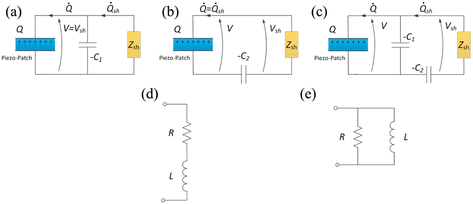
Piezoelectric shunt with NCs: (a) parallel, (b) series and (c) SP configurations; Zsh is a passive shunt impedance. When a resonant shunt is considered, this impedance Zsh is made from an inductance L and a resistance R connected in either (d) series or (e) parallel. Refer to the main text of the section entitled ‘Coupling of an NC with an arbitrary impedance’ for the definitions of the other symbols in the figure.
All the mentioned analyses will allow developing guidelines for how to apply shunt damping by coupling NCs and resonant circuits. These guidelines aim to explain the best layout to be used for a specific case and how to enhance the stability of the EMS.
Therefore, this article uses a mathematical approach previously developed to describe shunt damping through NCs coupled to a resistive shunt to describe the damping offered by NCs coupled to a resonant shunt. This allows the authors to reveal many features of this specific damping approach, as explained in the previous list.
The remainder of this article is structured as follows. The next section describes the theoretical model employed in this article. The subsequent section analyses the stability of the EMS when coupled to IC NCs and provides the analytical expressions to be used for optimising the values of the elements of the shunt impedance, as well as the expressions of the associated vibration attenuation. Then, the article shows the effect of using RC NCs and provides the mentioned guidelines for using NCs coupled to a resonant shunt. Finally, the last section of the article describes the experiments conducted to validate the theoretical results.
Model of the EMS
Coupling of an NC with an arbitrary impedance
The model used here was originally developed in the works of Thomas et al. (2009, 2012) and Ducarne et al. (2012) and then improved in the works of Berardengo et al. (2016b, 2017), where a deeper insight into the electrical behaviour of the EMS enables a better description of the system dynamics, thereby improving the accuracy of the original model. Only the parts of the model that are fundamental for a deep understanding of the article are reported in this section. Readers can refer to the referenced works for a detailed description of the model. From the next subsection (i.e. the subsection related to the coupling between a resonant shunt and NCs) on, the new outcomes related to the coupling between NCs and a resonant shunt are addressed.
A generic elastic structure with one piezoelectric patch bonded on it and excited by an external force

where
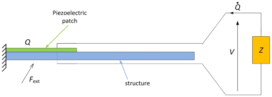
An arbitrary structure with a piezoelectric patch connected to a passive shunt impedance Z.
In the case of low modal density and if a single-degree-of-freedom (SDOF) approximation is considered by keeping only the ith mode in the modal truncation, the behaviour of the EMS can be described for


where equation (2) is the equation of motion of the EMS, and it is coupled to the EMS electrical behaviour, described by equation (3), through the coefficient
The term

where
The model described by equations (2) and (3) is related to the case of a simple piezoelectric shunt where no NCs are included in the circuit. The addition of IC NCs is now addressed according to the network layouts described by the schemes in Figure 1(a) to (c). RC NCs will be considered later in this article (i.e. in the section related to the effects of the NC implementation on system stability and damping performance). The passive shunt impedance in the circuit without NCs was referred to as Z in Figure 2. Conversely, the passive shunt impedance is referred to as
The following change in variables is now introduced

here,


Parameters of the EMS without NCs, enhanced by a single NC in parallel and series configurations and enhanced by two NCs for the SP configuration.

EMS: electromechanical system; NC: negative capacitance; SP: series + parallel.
Equations (6) to (8) describe the electromechanical behaviour of the EMS when NCs are added in the electric circuit. These equations play the same role as equations (2) and (3): the latter are related to an EMS without NCs, whereas the former are related to an EMS with NCs. Note that equations (6) and (7) are equivalent: they both describe the EMS motion, but one is expressed as a function of

Note that if we fix

The MEMCF measures the energy transfers between the electric circuit and the ith mode, and vice versa, through the electric network. The EMEMCF is a parameter that is analogous to the MEMCF, but it accounts for the presence of the NCs (the NCs improve the energy transfers because
Note that once the value of
Coupling between resonant shunt and NCs
Equations (6) to (8) describe the electrical and mechanical behaviours of the EMS when NCs are added to the EMS, and
In the case of a parallel link between R and L, the following relation in the frequency domain links the voltage

where

Conversely, in the case of a series connection between R and L, the following relation holds

which leads to the following FRF

In the above equations,
Definitions of
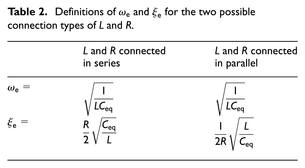
If the FRF
Stability and performance
The FRFs between a generic force
Stability
When an NC is used in the shunt circuit, the stability of the EMS must be verified. Indeed, the addition of NCs can cause instability due to the active nature of these components.
The stability of the EMS can be studied by applying the Routh–Hurwitz criterion (Gopal, 2002) to the FRFs of equations (12) and (14) considering both series and parallel NC layouts. The shunt circuit should always be taken into account in the analysis because it can change the stability conditions (see, as an example, the stability limits found in Berardengo et al. (2016b) for the resistive shunt coupled to NCs compared to the slightly different ones derived in De Marneffe and Preumont (2008)). To derive a closed mathematical expression for the stability conditions, the structural damping was initially neglected (i.e.


Then, numerical simulations were performed to determine whether a non-null damping could change these conditions. The simulations revealed that the stability conditions are not affected by a non-null value of
The conditions of equations (15) and (16) were derived using equations (14) and (12), which describe the EMS behaviour when an SDOF approximation is taken into account. Therefore, they are related to only one mode of the EMS. Nevertheless, when stability is studied, all the modes must be taken into account to avoid spillover effects. Therefore, the stability conditions of the entire EMS must be intended as the ones related to the modes with the strictest limits. These conditions are as follows


where
A similar approach can be used for the SP layout and leads to the following result

There are two conditions for the SP configuration because there are two NCs in the circuit. Notably, the conditions of equations (17) to (19) are equal to those found in Berardengo et al. (2016b, 2017) for a resistive shunt coupled to NCs.
Optimisation
Although several studies in the literature aimed to derive rules for the resonant shunt optimisation (e.g. Hagood and Von Flotow, 1991; Soltani et al., 2017; Thomas et al., 2012; Yamada et al., 2010), few of them accounted for the presence of NCs (e.g. Neubauer et al., 2006) and the performance and robustness with this type of enhanced shunt circuit. Among these few studies, few of the possible shunt circuit layouts were considered; this also prevents a comparison among all the possible shunt layouts. In this scenario, this section aims to derive general analytical formulae for the tuning and the performance estimation of the resonant shunt coupled to NCs, starting from the general analytical model derived previously. Therefore, thanks to the common formulation for all the NC layouts (see equations (6) to (8)), the formulations derived in the following will have a general validity and can be used for any NC configuration. Moreover, because the description is based on non-dimensional parameters (i.e.
Note that the values of the elements composing the electrical circuit must be optimised if a high control performance is required. Indeed, the resonant shunt is not robust to mistuning, and thus, a perfect tuning between the mechanical and electrical parts of the EMS is needed (Berardengo et al., 2015a, 2016a).
Optimisation of the NC
With regard to the IC NC, it is already explained in the literature (Berardengo et al., 2016b) that the closer the NC is to
To better determine the NC value that allows the best possible attenuation performance while guaranteeing stability, it is convenient to define the following indices

The index
Consequently, it is easy to understand that IC NCs in series are convenient for enhancing the EMEMCF of the low-order modes because this layout allows reaching higher
Optimisation of the inductance
The optimisation of the value of
If we initially consider an EMS with


Then, using the expressions in Table 2, the corresponding optimal value of the inductance,
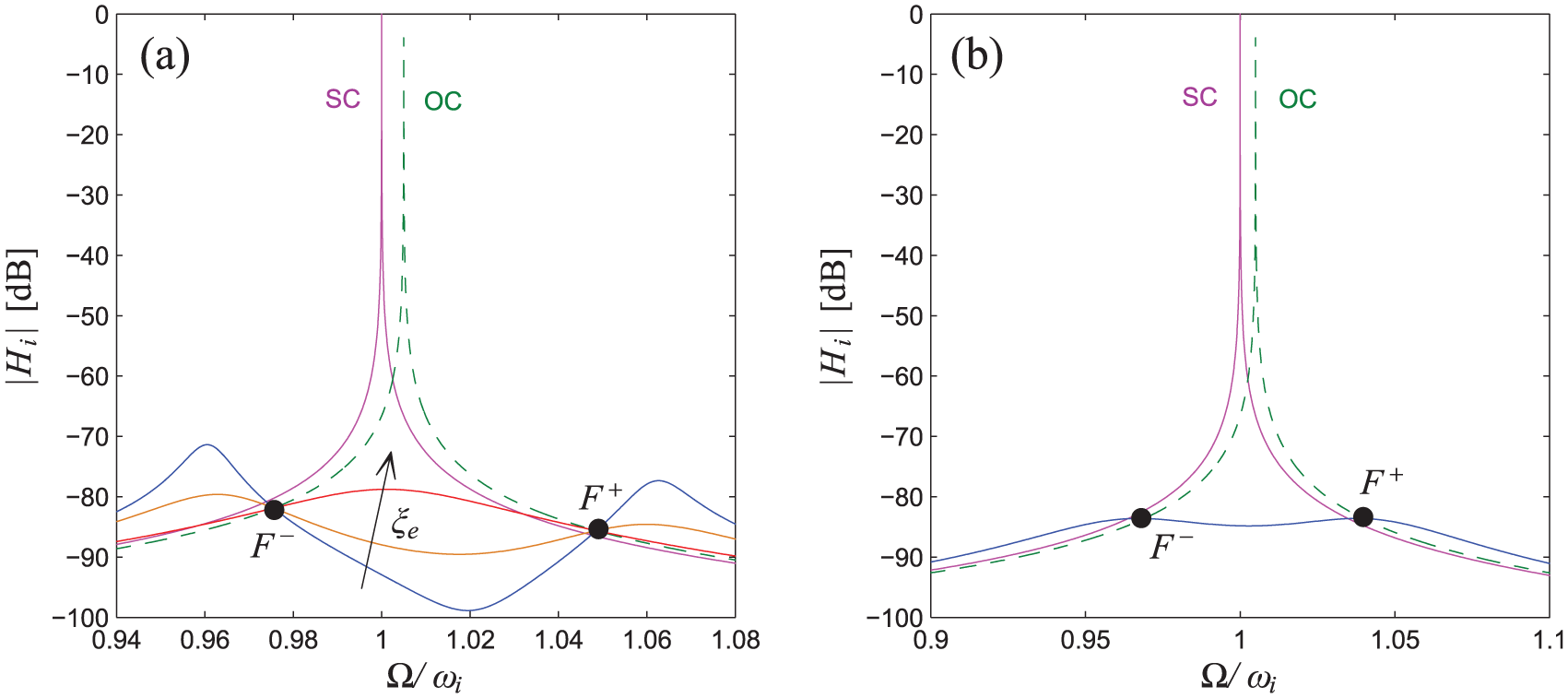
(a)
Optimisation of the resistance
The optimal choice for


Then, using the expressions presented in Table 2, the corresponding value of the optimal resistance
A remarkable result of equations (21) to (24) is that a common mathematical description can be found for all the possible NC layouts. Moreover, these mathematical expressions are valid even in the case of a simple resonant shunt without NCs. Indeed, equations (21) to (24) when no NCs are used in the shunt circuit are in agreement with the formulations proposed by Yamada et al. (2010) for the pure resonant shunt without NCs. Notice that if mobility or accelerance is taken into account in place of the dynamic compliance, the optimisation formulae are slightly different (Andreaus and Porfiri, 2007; Yamada et al., 2010).
The detailed procedure used to find
Expressions of

Attenuation performance
To have an estimation of the achievable attenuation, the vibration reduction provided by the resonant shunt coupled to NCs is approximated here using the attenuation index

where

while the expression of

where


The expressions of equations (27) and (26) can be rearranged using the expressions of Table 1 to obtain the expression of
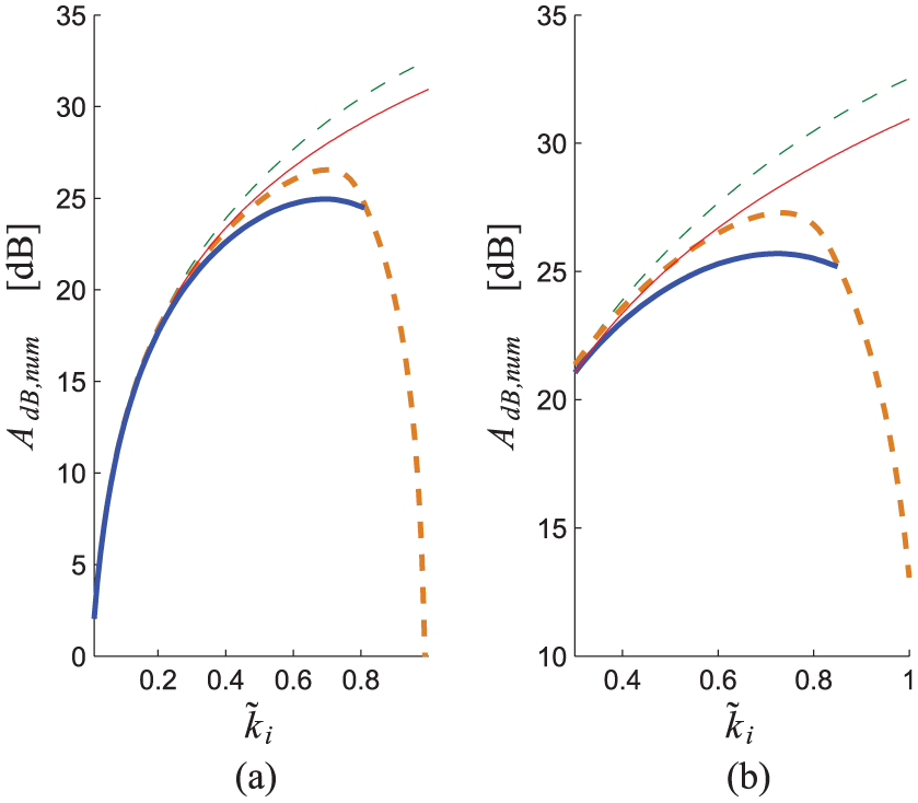
Figure 4 shows the performance of the different shunt configurations for three different
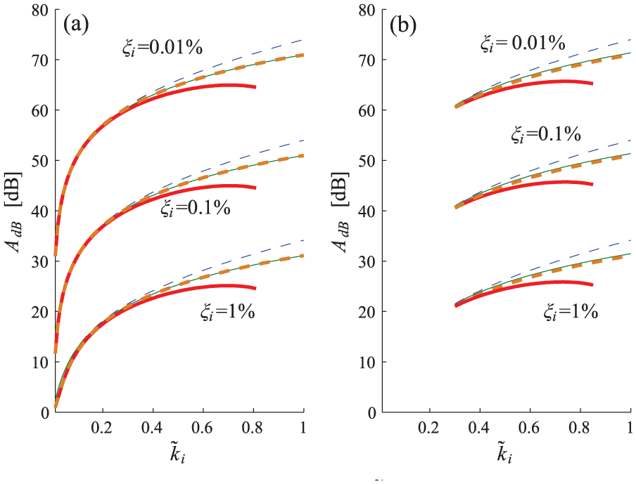
Figure 4 shows that the NC in the parallel configuration provides better attenuation compared to the NC in series with the same value of
Notably, for
For the NC SP layout (see Figure 5), the curve of
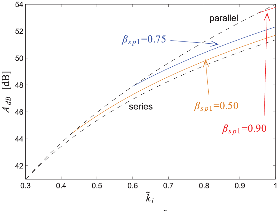
The attenuation provided by different NC layouts is thus different for high
The previous analysis has been performed using optimisation criteria that neglect the structural damping. With non-zero structural damping, the gain curves no longer cross at points
First, the connection between R and L in series is taken into account. The case of R and L in parallel will be addressed later in this section. Figure 6 shows the
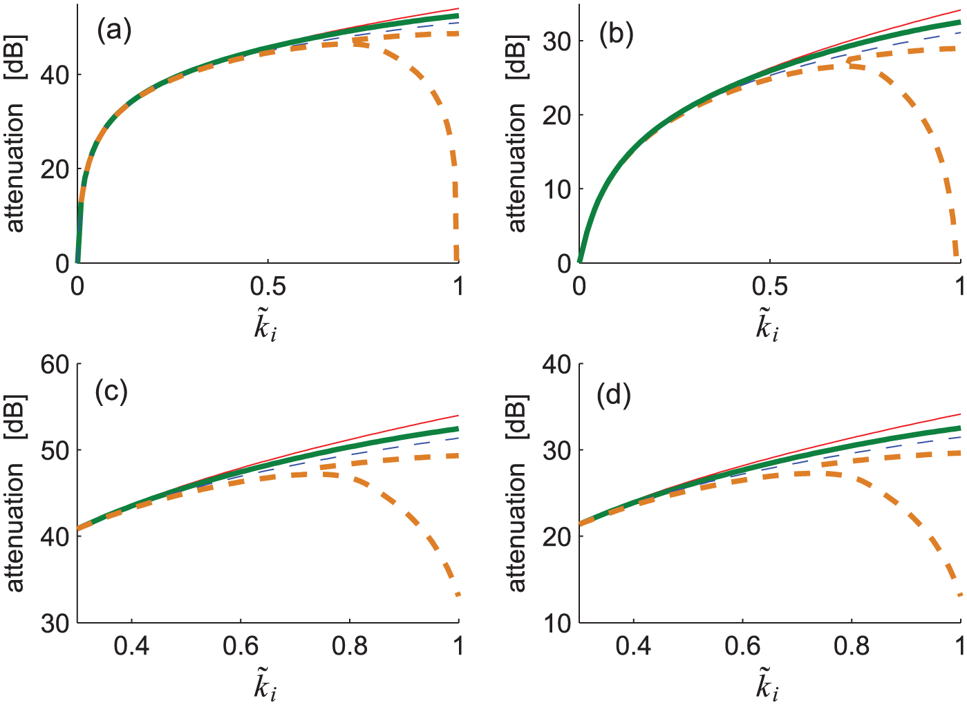
The series and SP NC layouts make the SC eigenfrequency shift towards increasingly lower frequency values (Berardengo et al., 2016b, 2017; De Marneffe and Preumont, 2008). When such a shift is high (i.e. with high
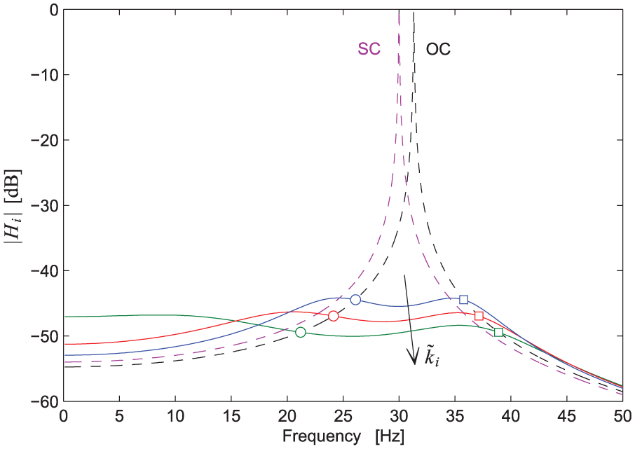
Note that the attenuation provided by the index
Regarding the connection of L and R in parallel,
Figure 8 provides a comparison between the attenuations
A further remarkable result is shown in Figure 9, where the dynamic magnification factor

Figure 9 shows that for
The upper one composed of the curves related to NCs in series and
The group in the middle is composed of the curves related to NCs in series and R and L connected in series and of the curves related to NCs in parallel and R and L connected in parallel;
The lower one composed of the curves related to NCs in parallel and R and L connected in series.
For the SP layout, its curves are always between those of the parallel and series layouts, according to the value of
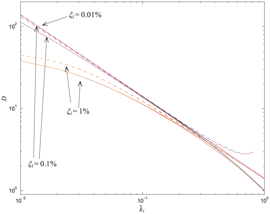
Trend of
A remarkable result is that impedances composed of an NC in parallel and R and L connected in series are able to make D lower than 1 when
Figures 7 and 9 show that the use of the classical resonant shunt together with the use of NCs can lead to the cancellation of resonance peaks. This is a remarkable result that reveals the high damping performance provided by this control approach.
This section (together with the following one) has allowed providing a complete comparison of the various connection layouts, together with evidence that the considered type of vibration damping allows achieving resonance cancellation, which is a remarkable result.
Advantages of the SP layout
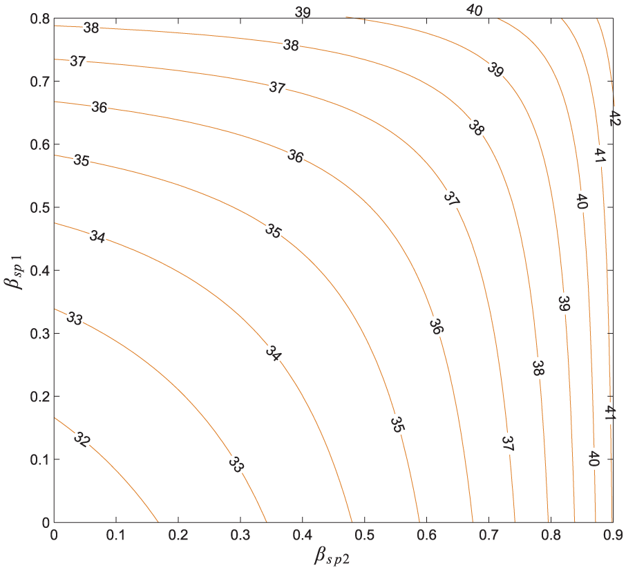
A remarkable benefit provided by the NC in the SP layout is that it can offer the same attenuation provided by NCs in either a parallel or series layout but staying further from the stability limits (i.e. lower β values). This is demonstrated by Figure 10, which shows the
Robustness of the vibration control
This section discusses the effect of mistuning on the values of
In this analysis, the mistuned values of
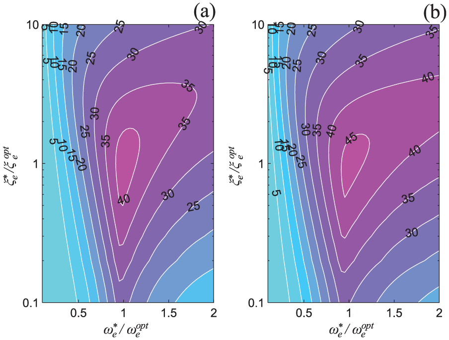
Figure 12 compares the different NC layouts; it presents some examples of the difference between the attenuation in mistuned conditions provided by IC NCs in series and in parallel configurations keeping the same R and L connection (i.e. plots (a) and (b) for R and L in series and plots (c) and (d) for R and L in parallel). It is evident that the NC in series offers almost the same attenuation compared to the NC in parallel when a mistuned condition is considered.
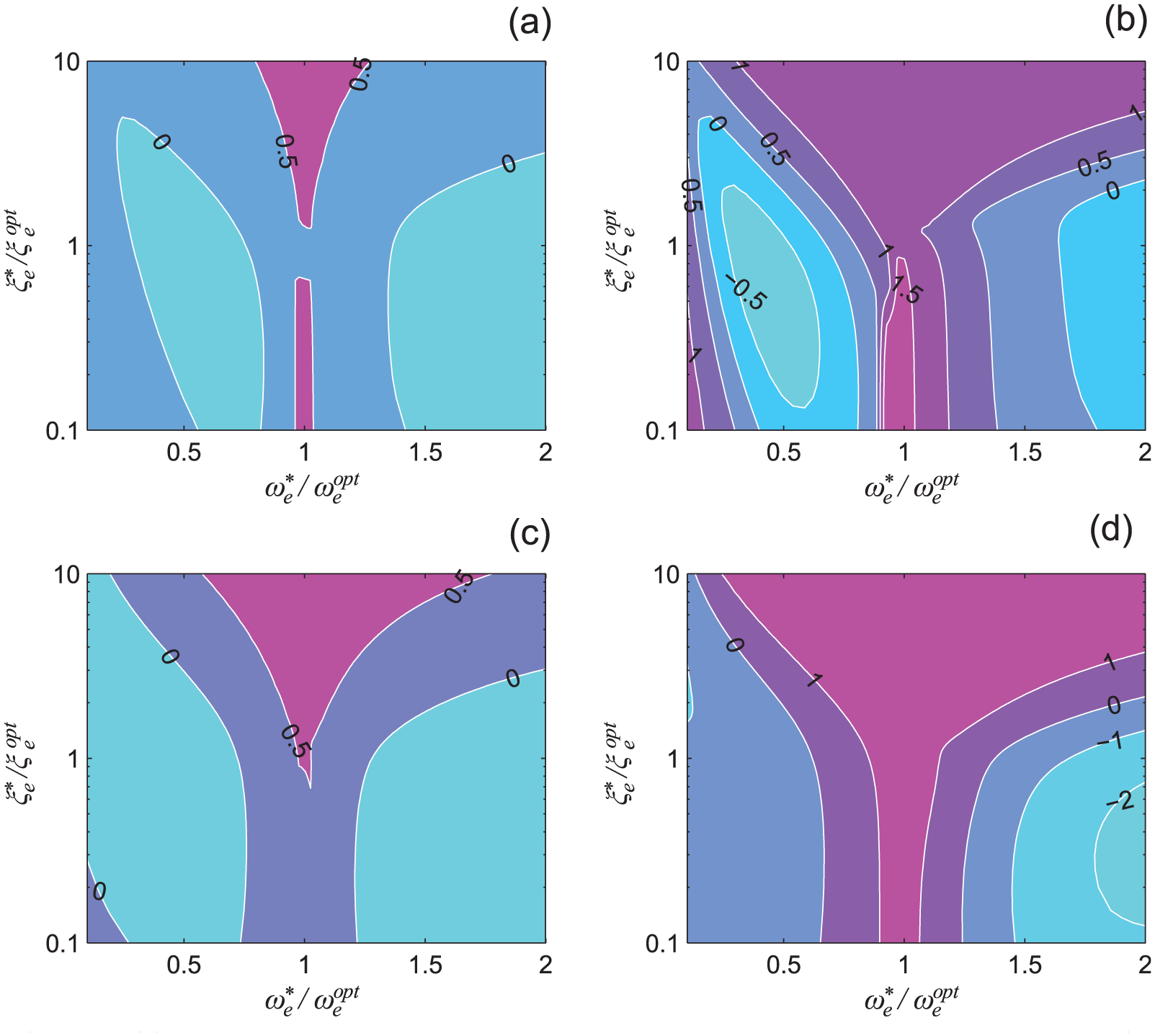
Figure 13 compares the effect on the robustness of the type of connection between R and L while keeping the same NC layout. Figure 13 shows the difference between the attenuation in mistuned conditions provided by R and L connections in series and parallel for an IC NC in parallel in plots (a) and (b) and in series in plots (c) and (d). It is evident that the parallel connection between R and L becomes highly advantageous when
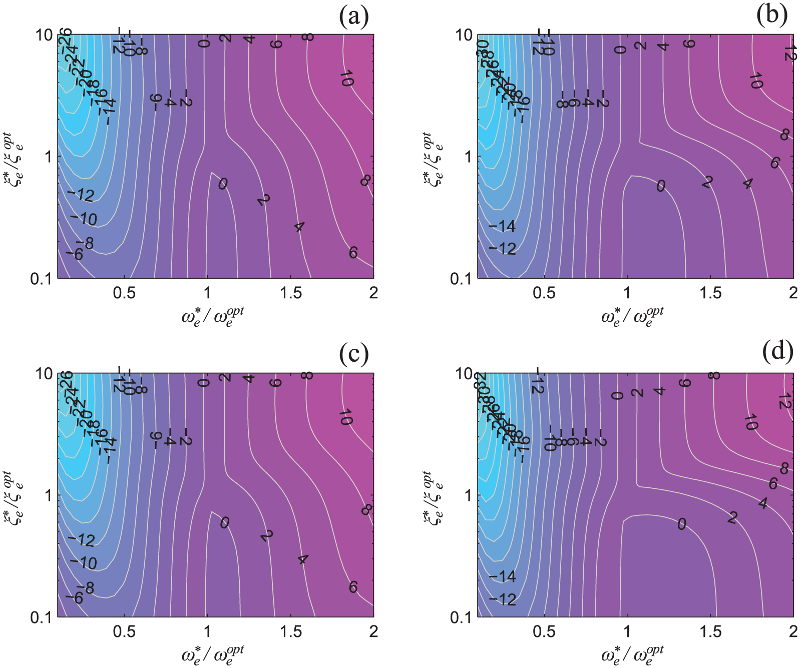
All the discussions presented thus far are related to IC NCs. The next section discusses the adoption of RC NCs. Therefore, the effects of the use of RC NCs on stability, tuning and performance will be addressed.
The effects of the NC implementation on system stability and damping performance
As mentioned in the introduction, in some cases, RCs must be used in place of ICs because of their higher reliability. The aim of this section is not to explain how to build RCs but rather to illustrate the effects of RCs coupled to a resonant shunt on the damping performance and stability of the EMS. Indeed, there are many differences in terms of EMS behaviour compared to the case of using ICs, and this point is often neglected in the literature, even if it is important to consider it to ensure an effective damping action. To this end, a brief introduction about how to construct RCs is presented herein to make the overall discussion clear.
The IC NCs can be practically built using an OP-AMP. Among the different possible circuit layouts available in the literature (Berardengo et al., 2016b), we consider only two of them here, as shown in Figure 14(a) and (b). These two circuits can be viewed as pure NCs, where the global NC at the circuit terminals, generically called

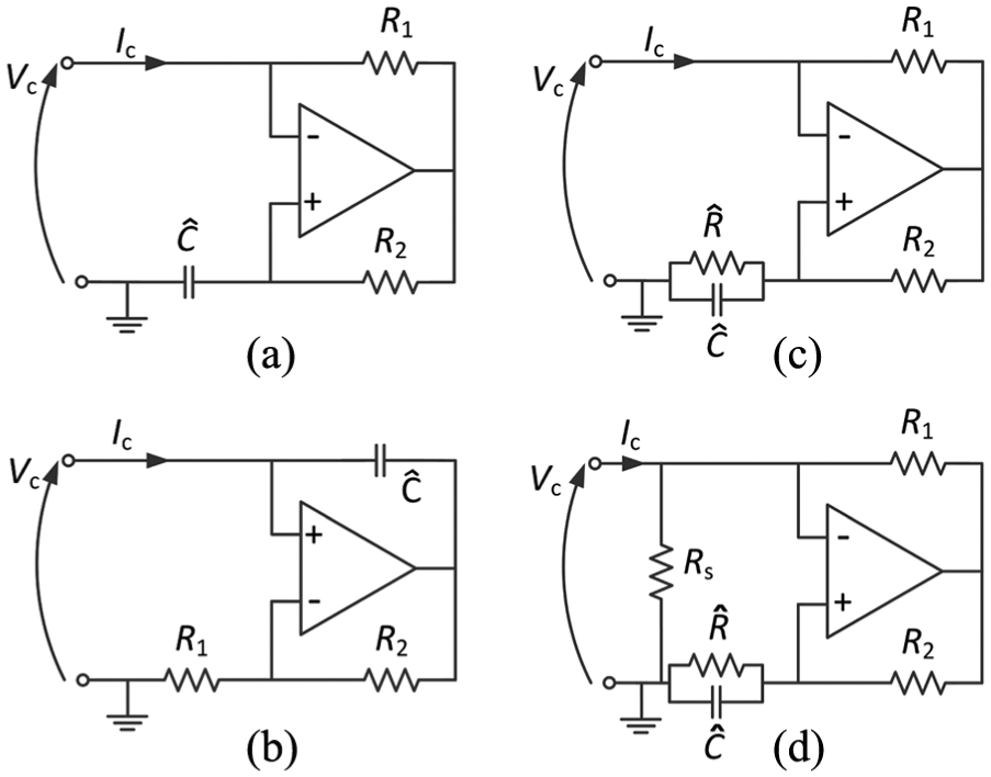
Practical implementation of NCs: (a) IC NC for connection in series (as well as for the series part of SP), (b) IC NC for connection in parallel (as well as for the parallel part of SP), (c) RC NC for connection in series (as well as for the series part of SP) and (d) the use of the compensation resistance in RC NC for connection in series (as well as for the series part of SP).
When NCs in series (as well as the series part of the SP) are considered, an additional resistance

The effect of

This section analyses the effect of the value of
Performance analysis
As mentioned previously, IC NC circuits and RC NC circuits exhibit different behaviour in the low-frequency range. When
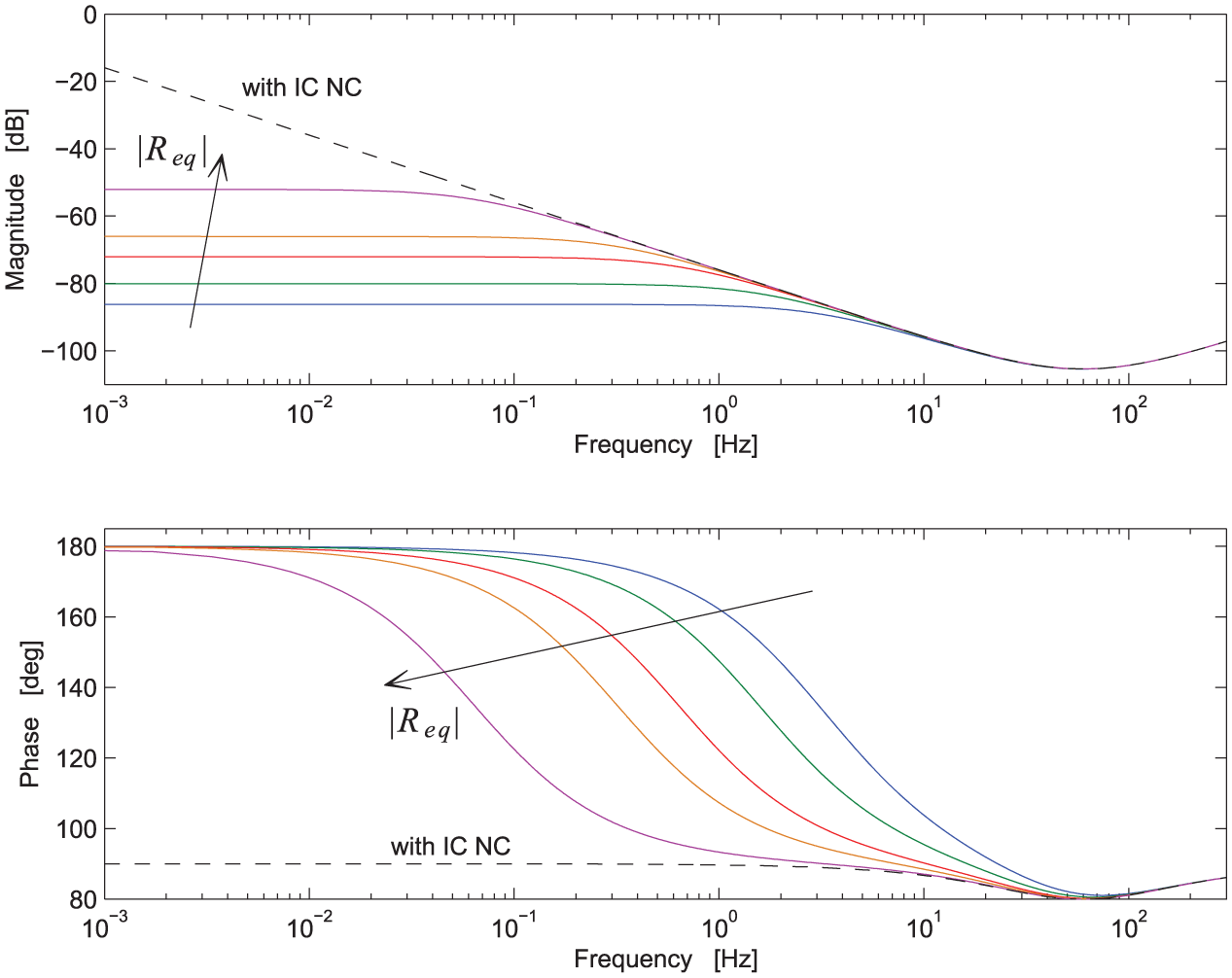
Magnitude and phase of the impedance
Using an approach similar to that employed for IC NCs, it is possible to find the SDOF FRF,

where


and


Then, from the FRF expression of equation (35), it is possible to derive the attenuation performance, named
Figure 16 shows
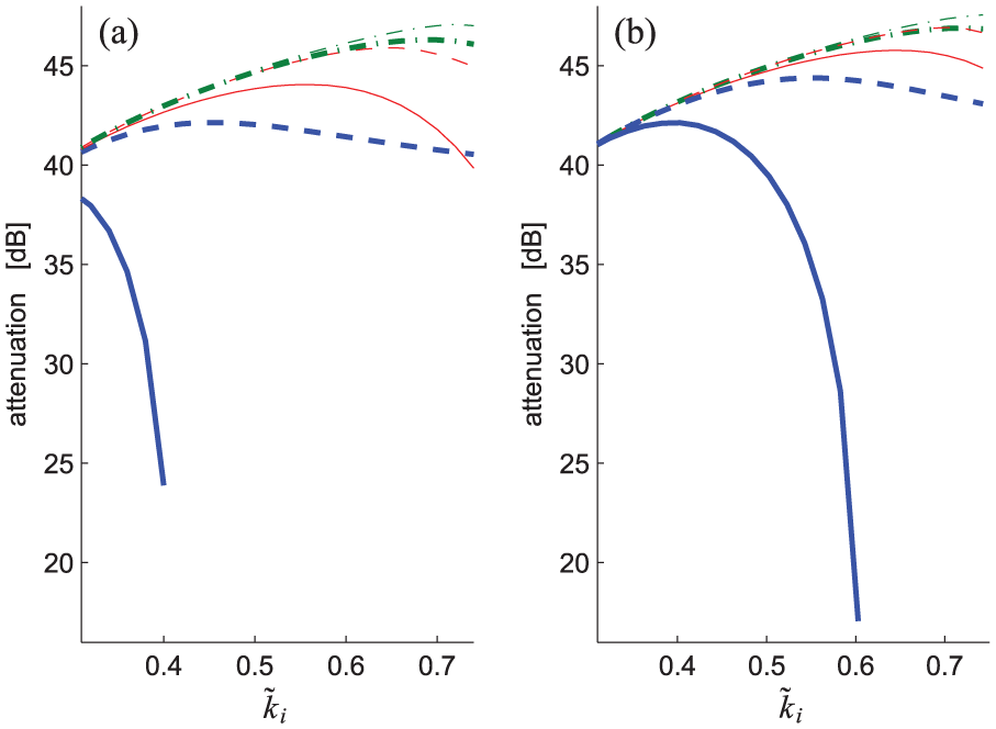
Trends of
When
Stability analysis
The previous subsection has shown that the use of RC NCs deteriorate the attenuation at low frequency if
The issue related to the stability of the EMS when using RC NCs in series can be further deepened, taking into account the fact that all the modes of the EMS must be stable, not only those on which the control action is focused. Consider, as an example, an EMS with two modes at
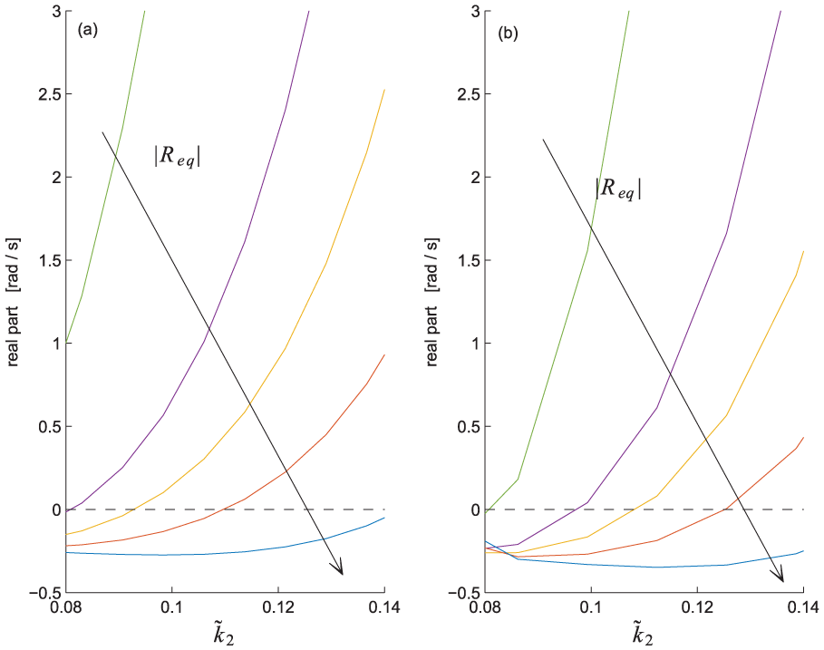
Trend of the real part of the pole related to the first mode, which can become unstable due to a low value of
A remarkable result provided by the SP configuration is shown in Figure 17(b). Here, we consider the same system as in Figure 17(a), but the SP configuration is used for the NC: here, the NC in series is built as an RC NC, while the parallel NC is an IC NC (see Berardengo et al., 2016b for more details). The comparison of Figure 17(a) and (b) indicates that the SP configuration improves the stability of the EMS compared to the series NC. Indeed, with the SP configuration, it is possible to use higher values of
Guidelines for coupling NCs to resonant shunt
All the previous analyses allow developing guidelines about how to apply shunt damping by coupling NCs and resonant circuits. Indeed, several choices are available for the NC connection and the layout of the link between R and L; the previous analyses allow highlighting the best choice as a function of the specific application.
The first choice is related to the configuration between R and L. The series connection must be preferred when the EMEMCF is high because it offers better attenuation performance (see previously in the article the subsection related to the attenuation performance provided by IC NCs). When the EMEMCF is not high, the differences between the two connection types tend to become negligible (see the subsection related to the attenuation performance provided by IC NCs). However, another point that must be taken into account is the practical implementation of L. It is often built using OP-AMPs because of its high value (Moheimani and Fleming, 2006; Thomas et al., 2012), and these circuits can generate additional resistances. When the series connection is considered, it is straightforward to compensate these resistive parasitic effects by changing R accordingly. Therefore, the series connection must be preferred.
For the NC layout, the choice depends on the considered frequency range. When high-order modes are taken into account, it is possible to choose between the parallel and the SP layouts. The parallel layout provides the advantage that IC NCs can generally be employed, while the SP layout can often require the use of RC NCs (for the NC in series). In the latter case, despite the presence of an RC NC, the circuit can be considered as ideal in terms of attenuation performance because the control is at high frequency (where the RC NC behaves as an IC NC). However, the stability is affected by the presence of an RC NC, and thus, the stability of the low-order modes must be checked. It follows that the use of the compensation resistance Rs is strongly encouraged if the stability must be improved.
With regard to low-order modes, the parallel NC typically provides low performance because the value of
Finally, when modes in the middle frequency range are taken into account, the SP shows performance and stability that are better than the series and the parallel layouts.
Generally, the use of the SP layout is suggested in almost all the cases, possibly coupled to the use of the compensation resistance Rs when RC NCs are used.
Experimental tests
This section presents the experimental tests conducted to validate the outcomes of the previous sections. The next subsection describes the set-up used for the tests. Then, the subsequent subsection validates the theoretical formulations derived for IC NCs, and the last subsection validates the results for RC NCs.
Experimental set-up
The set-up used consisted of a stainless steel cantilever beam (length 180 mm, width 30.5 mm and thickness 1.1 mm) with two piezoelectric patches (length 70 mm, width 30.0 mm and thickness 0.55 mm, material PIC 151) bonded at the cantilevered end. The two patches were electrically connected in series.
The structure was excited using a contactless actuator composed of a coil and a magnet bonded close to the beam tip (see Figure 18). Making current flow in the coil allowed exerting a force on the beam; this force was considered proportional to the current flowing in the coil (Thomas et al., 2003), which was measured using a current clamp. The response of the structure was measured using a laser Doppler velocimeter at a point close to the tip.
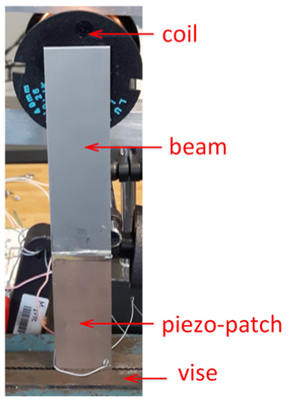
The experimental set-up.
Eigenfrequencies and non-dimensional damping ratios were estimated through an experimental modal analysis with the piezoelectric patch short-circuited. The algorithm employed for modal parameter extraction was the polyreference least squares frequency-domain method (Peeters et al., 2004). The ki values were estimated by measuring
For the
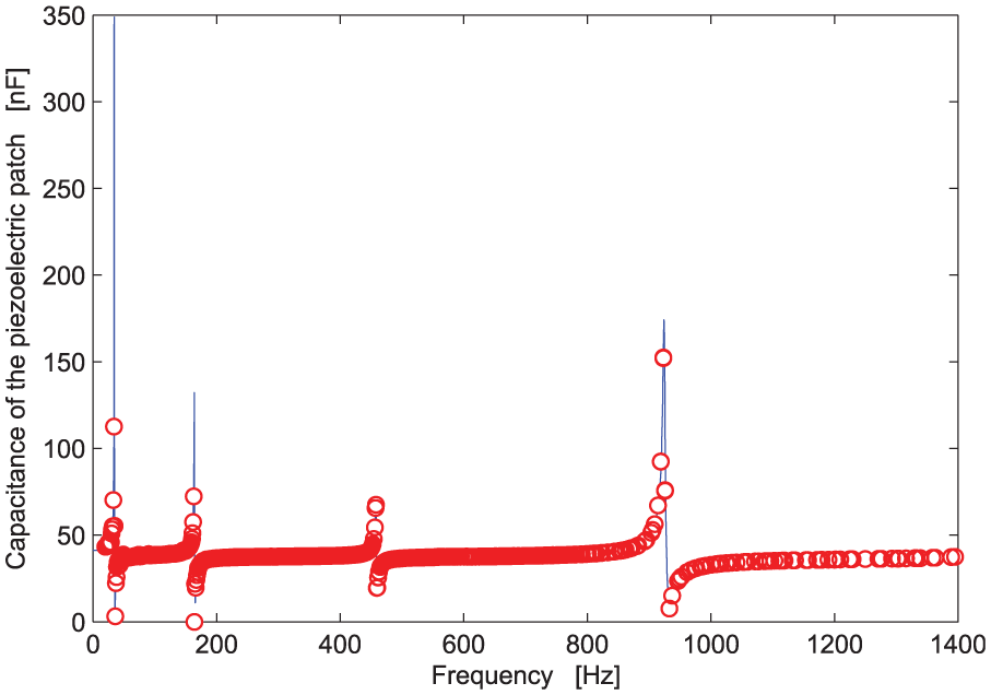
Trend of the modulus of the piezoelectric capacitance as a function of frequency. Points are related to experiments, while the line is the interpolated model.
The NCs were built using Texas Instruments OPA445 OP-AMPs. The NC in parallel (as well as the NC in parallel in the SP layout) was built using the electrical scheme shown in Figure 14(b); we used the schemes shown in Figure 14(c) and (d) for the NC in series, as well as for the NC in series of the SP layout.
The inductance L was built using a synthetic circuit based on Antoniou’s circuit (Thomas et al., 2012; Von Wangeheim, 1996) employing OP-AMPs OPA445 (see Appendix 3). The use of a synthetic circuit was due to the high inductance values in the different tests, which prevented the use of physical inductances. All the OP-AMPs were supplied with a direct current (DC) voltage of ±30 V.
Experiments with ICs
This section discusses the tests performed on the first mode of the beam to validate the formulations derived for the values of
Description of the parameters for the experimental tests.

Figures 20 to 22 show the experimental results for NCs in parallel, series and SP, respectively, achieved by employing equations (21) and (23) for the shunt tuning. There is a satisfactory agreement between the theoretical expectations (equation (26)) and the experimental results. The curve related to the parallel NC (Figure 20) cannot be experimentally investigated for
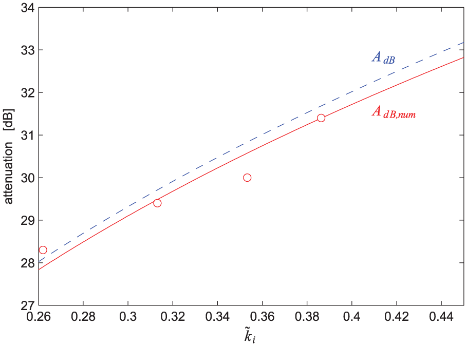
Comparison between experimental results (circles) and theoretical expectations (solid and dashed curves) for NC in parallel (Test A column in Table 4).
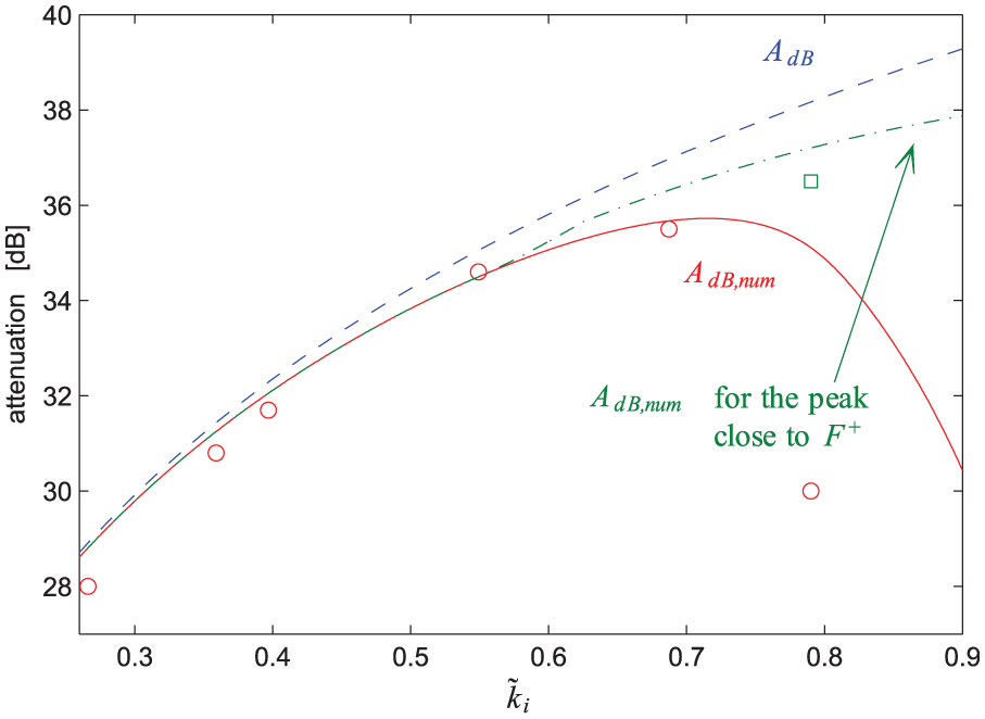
Comparison between experimental results (circles) and theoretical expectations (solid and dashed curves) for NC in series (Test B column in Table 4). The green dashed-dotted curve is related to the values of
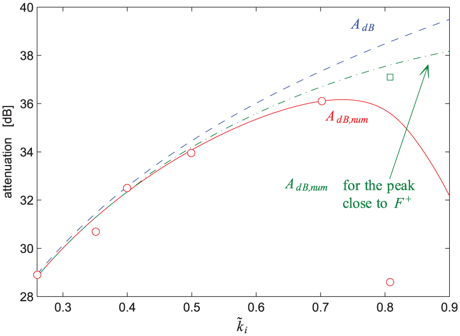
Comparison between experimental results (circles) and theoretical expectations (solid and dashed curves) for NCs in SP (Test C column in Table 4). The green dashed-dotted curve is related to the values of
Note that during these tests, the circuit composed of the series connection of L and R was measured every time using a network analyser. Indeed, when an inductance is built using OP-AMPs, there is a possibility of having a parasitic resistance in series (Park and Inman, 2003; Viana and Steffen, 2006), as already mentioned. Therefore, we measured the entire circuit to stay as close as possible to the optimal values of the shunt inductance and resistance.
The only experimental points in Figures 21 and 22 where there is not a strict agreement with theory are those related to
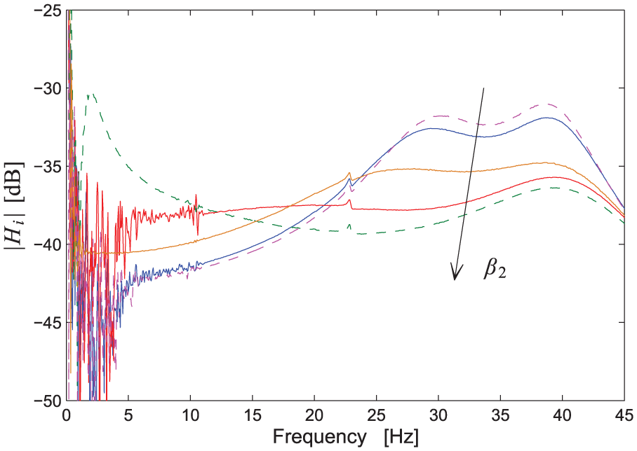
According to the outcomes of the subsection related to the attenuation performance provided by IC NCs, we also know that the SP layout offers higher attenuation performance compared to the series and parallel layouts when the same
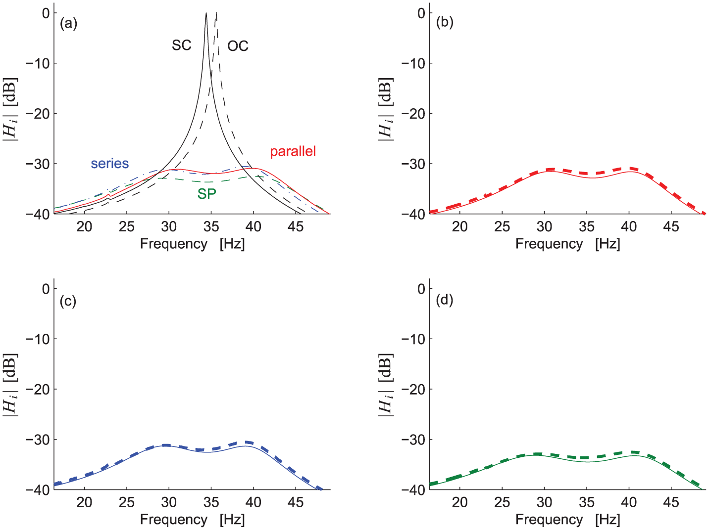
FRFs with IC NCs for
Finally, some tests performed to validate the attenuation performance in mistuned conditions are shown. Figure 25 shows the comparison between experimental attenuations (blue circles in Figure 25) and the theoretical expectations (the isolines in Figure 25). Again, the agreement is good, thereby confirming the reliability of the theoretical model.
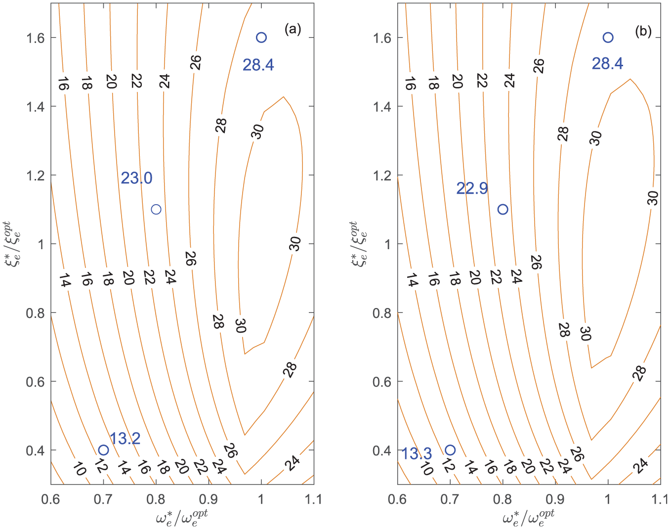
(a)
Experiments with RCs
Figure 26 shows the comparison between the experiments and theory for an RC NC connected in series to the series of an inductance and a resistance. Different values of
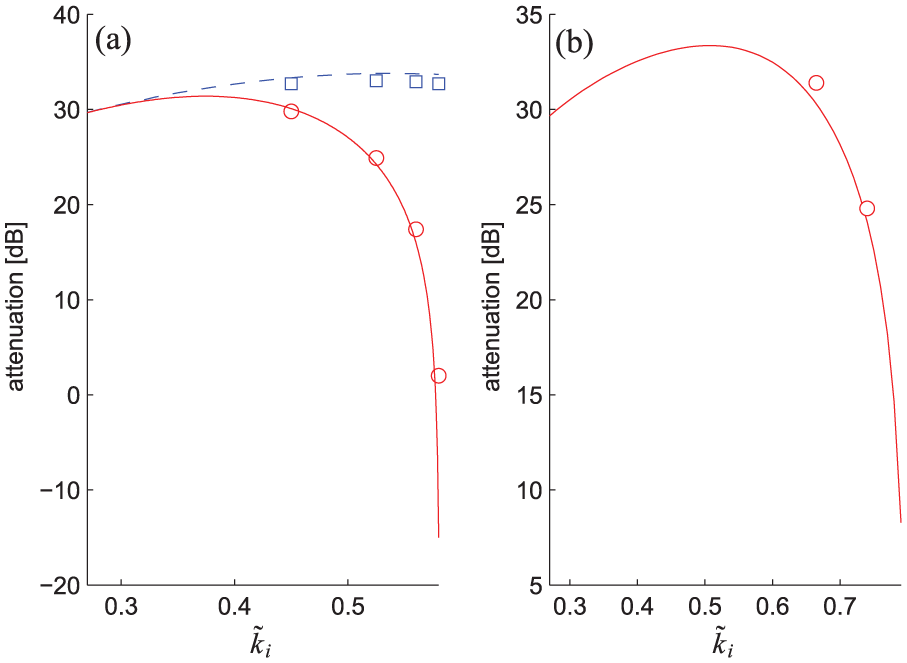
Trends of
In the test of Figure 26(a) (where
Another test (Test E, see Table 5; the values of the electrical parameters are almost the same of those provided in Table 4) was performed regarding the instability of RC NCs. The aim of this additional test is to show the benefit provided by the use of NCs in the SP configuration compared to the NC in series. In this case, the shunt impedance was tuned on the second mode of the beam (using
Test E: modal data of the first two modes.

Note that the FRF
The use of the SP configuration allows decreasing the value of
The comparison between the experimental and theoretical results is provided in Table 6, and the agreement is also good for this test, even if slight differences occur. Actually, in this test, slight changes in the values of the parameters involved (e.g.
Values of

Conclusion
This article has addressed vibration damping by means of piezoelectric shunt. Specifically, the shunt layout taken into account is made from a resonant shunt coupled to NCs.
A common mathematical formulation has been shown to exist for all the possible layouts of the NCs (i.e. parallel, series and SP) regarding the optimisation of the shunt parameters and the consequent achievable vibration attenuation.
Since active elements (i.e. NCs) are considered in the shunt, stability conditions for the EMS have also been provided.
Furthermore, the behaviour of modified circuits, which cannot be considered as pure NCs but which must often be used in practical applications, has been analysed.
Finally, the advantages provided by the use of two NCs together, compared to traditional layouts where only one NC is used, have been highlighted in terms of both stability and attenuation performance.
All the mentioned analyses allowed developing some guidelines for facing different types of control problems to be provided, explaining how to improve performance and stability. The coupling between the classical resonant shunt and NCs is even able, in some cases, to provide an attenuation performance so high that resonance cancellation is achieved.
The theoretical results have been validated through an experimental campaign conducted on a cantilever beam coupled to a pair of piezoelectric patches.
Footnotes
Appendix 1
Appendix 2
Appendix 3
Acknowledgements
The authors are grateful to Prof. Giovanni Chiorboli (Università degli Studi di Parma) for the support in the measurement of the capacitance of the piezoelectric patch.
Declaration of conflicting interests
The author(s) declared no potential conflicts of interest with respect to the research, authorship, and/or publication of this article.
Funding
The author(s) received no financial support for the research, authorship, and/or publication of this article.
