
Abstract
Cross-shape piezoelectric patches were originally proposed to improve the band-gap properties of acoustic metamaterials with shunting circuits. The dispersion curves are characterized through the application of finite element method. Also, the theoretical band-gap predictions are verified by simulation results obtained from COMSOL. The investigation results show that the proposed scheme distinguishes itself from the conventional square patches by broader band gaps, whose bandwidth is almost doubled. The inherent capacitance of the piezoelectric patch is strongly related to the boundary conditions, so the local resonant band gap is strongly affected by the shape of piezoelectric patches as well. As a result, the band-gap width and location of metamaterials with different shape patches are rather different, even with the same size patches. Also, negative modulus (NM) and Poisson’s ratio were observed around the resonant frequencies. The transmission properties of finite periods agree well with band-gap predictions. An obvious attenuation zone (AZ) is produced around the band-gap location, in which the wave propagation is decayed strongly. Similarly, the width of AZ of the proposed metamaterial is much larger than that of the conventional one. Hence, the proposed scheme demonstrates more advantages in the application to vibration isolation when compared with the conventional.
Introduction
In the past two decades, acoustic metamaterials have received enormous attention by researchers in physics and acoustical engineering (Fang et al., 2006; Ho et al., 2003; Liu et al., 2000; Park et al., 2015; Yang et al., 2008). Metamaterials are artificial composite devised to produce properties that may not be readily available in nature. The concept of metamaterials was primarily proposed in the field of electromagnetics (Shelby et al., 2001; Smith et al., 2000) and subsequently extended to the acoustics. Acoustic metamaterials demonstrate many physically unusual properties, such as negative mass density (Yang et al., 2008), negative elastic modulus (Fang et al., 2006), negative refraction (Feng et al., 2005), and sub-wavelength band (Xiao et al., 2012). Proposed applications are broad in scope, including cloaking (Zhang et al., 2011), diodes (Liang et al., 2009), acoustic superlenses (Park et al., 2015), vibration isolation, and sound insulation (Naify et al., 2010). Particularly, a relatively low-frequency regime, called sub-wavelength band gap has been observed in acoustic metamaterials, where the propagation of elastic waves is prohibited (Liu et al., 2000). The low-frequency bands provide potential solutions to the problem of low-frequency noise and vibration control, which is an ever-increasing requirement and challenging work for structural engineers. The exceptional properties of metamaterials are mainly produced by locally resonant mechanism, which was first brought forth by Liu et al. (2000). They periodically embedded locally resonant microstructures into a matrix material, resulting in a low-frequency band gap. The results demonstrated that the size of the microstructure is much smaller than the wavelength. Subsequently, wave propagation in acoustic metamaterials has been investigated intensively.
Recently, the investigations of acoustic metamaterials have been extended to smart metamaterials, whose physical properties can be actively tuned. There are many means to obtain a smart metamaterial, such as feedback control system (Akl and Baz, 2012; Baz, 2009), pressured air-controlled elements (Langfeldt et al., 2016), and piezoelectric shunting circuits (Airoldi and Ruzzene, 2011a; Chen et al., 2014). Particularly, acoustic metamaterials tuned by piezoelectric shunting circuits, which are easy to fabricate and own conveniently adjustable parameters, have attracted much attention. Airoldi and Ruzzene (2011b) proposed using multi-resonant shunting circuits to generate tunable multiple band gaps in a beam. Subsequently, they proposed to design one-dimensional tunable acoustic metamaterials through periodic arrays of resonantly shunted piezos (Airoldi and Ruzzene, 2011a). Wang et al. (2011) experimentally investigated the low-frequency locally resonant band gaps induced by arrays of resonant shunts with Antoniou’s circuit. Chen et al. (2013b) investigated dispersion curves and band-gap control of metamaterials with negative capacitance piezoelectric shunting circuits. The authors also conducted a lot of theoretical and experimental work on acoustic metamaterials with shunting circuits (Chen et al., 2013a, 2013b, 2016). However, rectangular and square piezoelectric patches are generally adopted in the published literature. So far, seldom efforts have been made to examine the influence of the piezo-shape to acoustic metamaterials. Limited by the small electromechanical coupling factor of available piezoelectric materials, the band generated by piezoelectric shunting circuit in low-frequency regime is usually rather narrow. To broaden band-gap width, the shape of piezoelectric patch is one of the crucial parameters. Therefore, the shape of piezoelectric patch should never be overlooked.
In this work, cross-shape piezoelectric patches are originally proposed to improve the band-gap properties of acoustic metamaterials with shunting circuits. Numerical calculation and finite element (FE) simulation are performed to investigate the band-gap properties and validate the improvement of cross-shape piezos. For comparison, a conventional metamaterial with square patches are analyzed as well. Specifically, the structure configuration and band structure calculation based on finite element method (FEM) are described in section “Configuration and modeling.” First of all, layout of the unit cell is graphically illustrated. Then, the unit cell is discretized by standard FE procedures. After that, periodic boundary conditions are applied to the discretized equations, whose solutions yield the dispersion curves. Also, effective modulus of the shunted piezoelectric patch is derived in detail. Numerical results and discussions are presented in section “Numerical results and discussions.” The dispersion curves are characterized and compared. Moreover, the wave modes corresponding to the bounding frequencies are examined in depth. Variation of effective modulus with frequency is analyzed as well. In section “Transmission properties of finite periods,” the transmission properties of finite periods are simulated in COMSOL. Finally, conclusions are summarized in section “Conclusion.”
Configuration and modeling
Layout of the acoustic metamaterial
The acoustic metamaterials are two-dimensional square lattice structures, whose unit cell is schematically illustrated in Figure 1. Specifically, Figure 1(a) demonstrates the proposed acoustic metamaterial with cross-shape piezos, while Figure 1(b) is the conventional acoustic metamaterial with square piezos for comparison. Both the acoustic metamaterials consist of a substrate plate (A) and a pair of piezoelectric patches (B) oppositely bonded to the surfaces of the plate. Each pair of piezoelectric patches is attached to an inductive circuit, whose inductance is denoted by L. In order to properly compare the two types of metamaterials and obtain the improvement of the proposed one, all the material and geometrical parameters are identical, except the shape of piezoelectric patches. Nevertheless, the cross-shape and square piezoelectric patches have the same area as well. As a result, the relation between δ and b can be expressed as follows


Unit cell of the (a) proposed and (b) conventional acoustic metamaterials.
The valid solution is

FE derivation of unit cells
The electromechanical modeling of the piezoelectric patches is based on the constitutive equations for piezoelectric materials. Under the assumption of plane stress deformation, the reduced constitutive equations can be expressed as follows
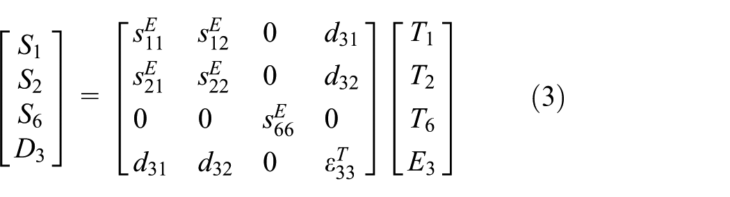
where
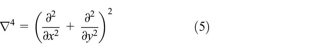
The governing equation for flexural motion of thin plates can be given by
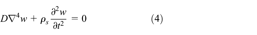
where w is the transverse displacement and D is bending rigidity. Also,
The assembly of substrate plate and piezoelectric patches as a lamina is modeled by FEM and meshed with 4-node Kirchhoff plate elements. Therefore, the discretized forms of the governing equations of the unit cell are derived by applying Hamilton’s principle and standard FE procedures (Spadoni et al., 2009), which give

where
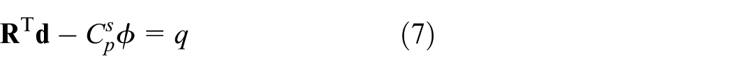
The piezoelectric patches are shunted by an inductive circuit, so the relationship between

Substituting equation (8) into equations (6) and (7) yields

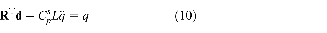
Reshaping equations (9) and (10) into matrix form obtains

where
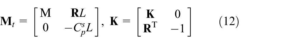
Assuming harmonic motion at frequency ω, equation (12) can be written as follows

Periodic boundary conditions
As the metamaterials are composed of unit cells arrayed in period format, periodic boundary conditions must be applied to the discretized matrix equation (13).
According to the location of nodes shown in Figure 2, the nodal displacement and force vectors
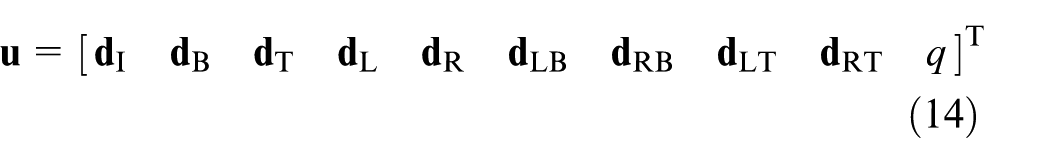
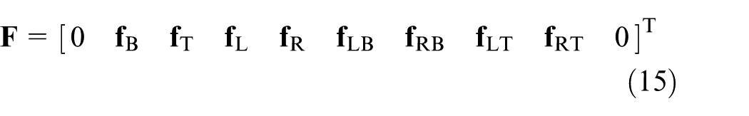
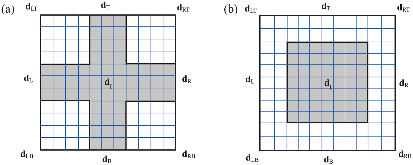
Depiction of the decomposition format. The subscripts “L”,“T”,“B” and “R” represent locations of the left, top,bottom and right boundary nodes.
Hence, the periodic boundary conditions can be expressed as (Farzbod and Leamy, 2009)
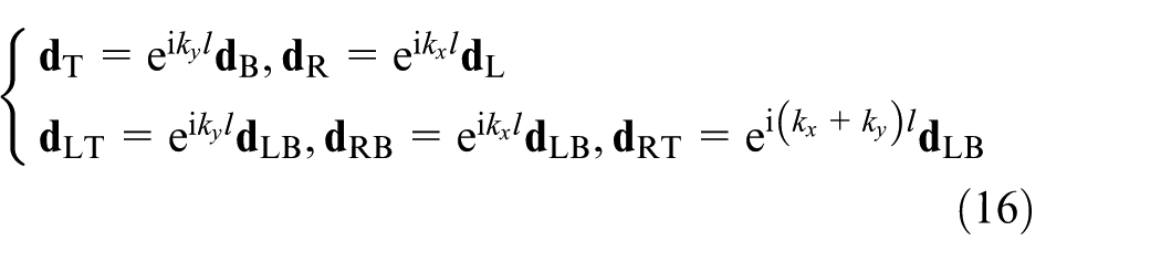
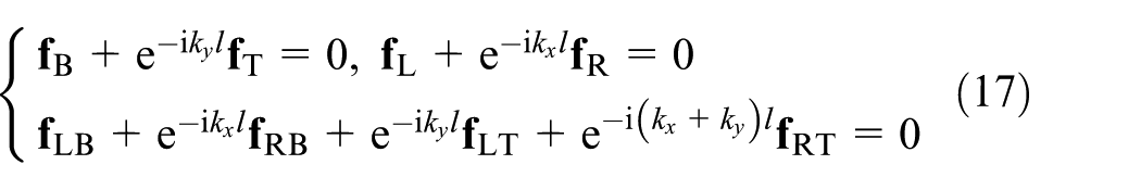
where
Substituting equations (16) and (17) into equation (13), it can be reduced to

where

Hence, the band structure of the metamaterials can be constructed by solving the eigenvalue equation (18). By sweeping the wave vector
Derivation of effective modulus
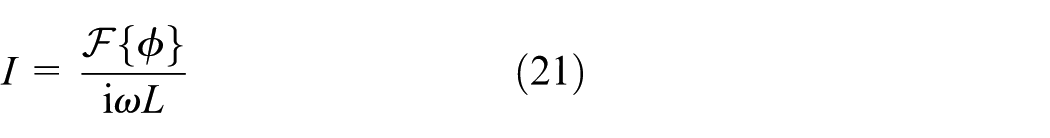
Under the condition of sub-wavelength wave propagation, the deformation in the piezoelectric patch is assumed to be uniform. Hence, the electric displacement on the electrodes must be uniform as well. As such, the electric current flowing in the shunting circuit can be expressed in complex form as follows

where ℱ is Fourier transformation operator, A is the area of electrode, and A = 2b2.
On the other hand, the electric current can also be solved as follows
Also, the electric potential difference can be given by

Substituting equations (20)–(22) into equation (3) yields
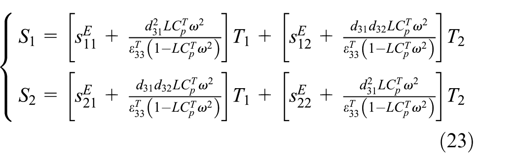
where
In the article, piezoelectric ceramic (PZT-5H) is selected as the material of the piezoelectric patches, whose elastic and piezoelectric parameters are identical in the x-axis and y-axis directions, that is

Therefore, according to the basic knowledge of elastic mechanics, the effective elastic modulus can be extracted as follows
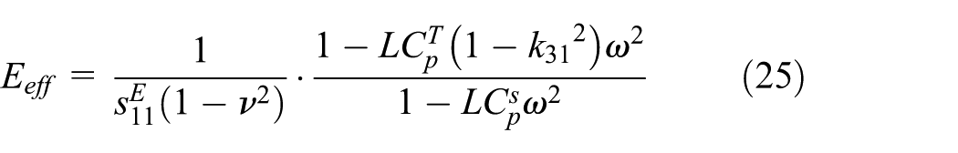
where k31 is the electromechanical coupling coefficient and
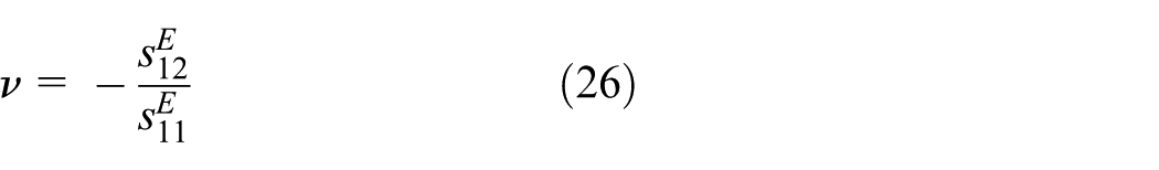
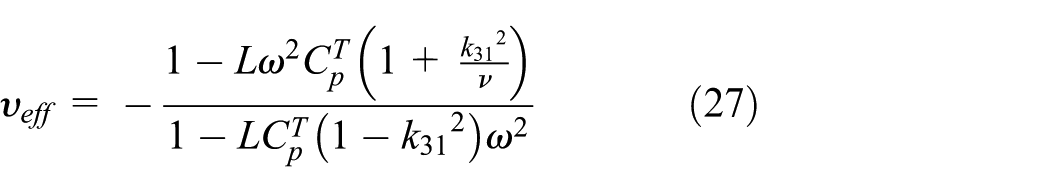
Also, the effective Poisson’s ratio is
Numerical results and discussions
Material and geometrical parameters
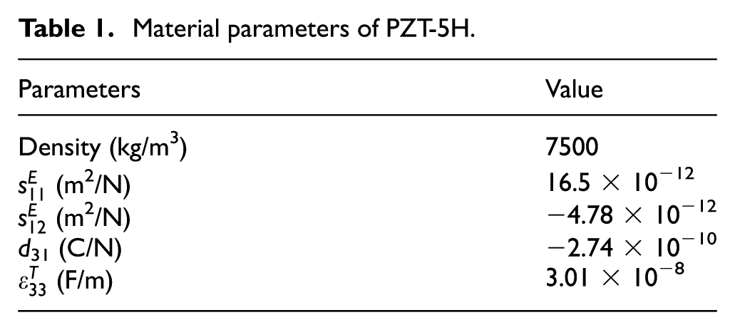
The metamaterials are made up of Aluminum (Young’s modulus E = 70 GPa, density ρ = 2700 kg/m3, Poisson’s ratio υ = 0.33) plate and PZT-5H patches, whose material parameters are listed in Table 1. The geometric parameters are listed as follows: h = 2 mm, a = 60 mm, b = 30 mm, and τ = 0.5 mm. Also, the inductance is selected at L = 800 mH.
Material parameters of PZT-5H.
Band structures and wave modes
The dispersion relations of the acoustic metamaterials are evaluated through a FE program built in MATLAB. The unit cells of the proposed and conventional metamaterials are meshed with 19 × 19 and 20 × 20 Kirchhoff plate elements, respectively. The final dispersion curves are plotted in Figure 3. Also, Figure 3(a) corresponds to the proposed one, while Figure 3(b) corresponds to the conventional one. It is observed that a locally resonant band gap is produced in both metamaterials, which must be induced by the resonant shunts. The band gap corresponding to the proposed metamaterial ranges from 606.47 to 631.45 Hz, while that corresponding to the conventional metamaterial ranges from 599.75 to 612.27 Hz. Therefore, the improvements of the proposed configuration are significant. The cross-shape piezoelectric patches can broaden the bandwidth, which is about twice of that corresponding the square patches.
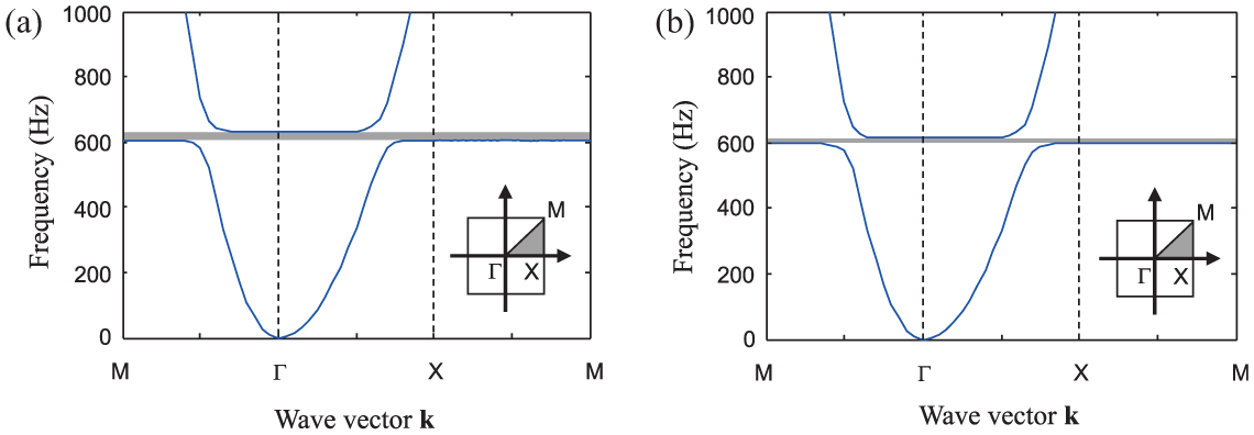
Dispersion relations of the (a) proposed and (b) conventional acoustic metamaterials. The inset depicts the irreducible Brillouin zone.
To ensure the accuracy of the above-mentioned FE results, the convergence with different element numbers is examined as shown in Figure 4. The two dotted lines represent upper and lower bounding frequencies of the locally resonant gap, respectively. It is observed that the bounding frequencies of the locally have converged under the adopted mesh schemes.
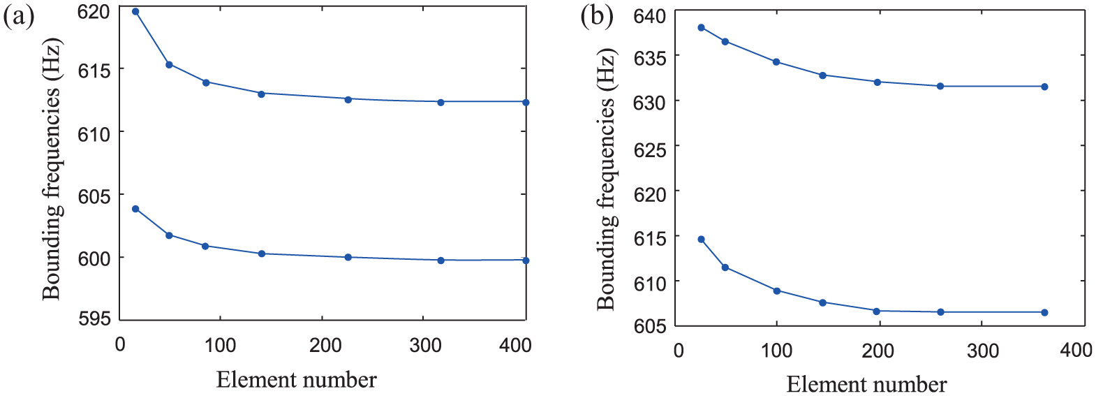
Convergence of the finite element results corresponding to the (a) proposed and (b) conventional acoustic metamaterials with different element numbers.
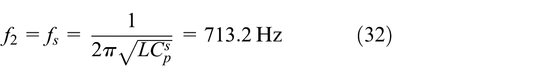
The resonant frequency of the shunting circuit is determined by the inherent capacitance of the piezoelectric patch and the shunting inductance. Hence, the frequency can be expressed as follows
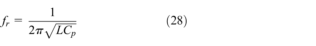
where
Obviously, the values
Substituting equation (27) into equation (26), the variation scope of resonant frequency can be determined as follows

where
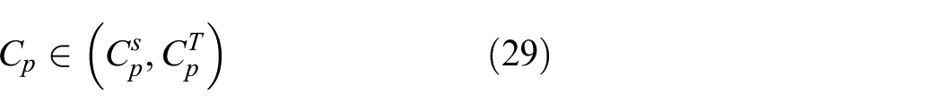
The wave modes of the proposed and conventional metamaterials corresponding to the lower bounding frequencies are illustrated in Figure 5. The shape of the wave modes is rather similar, that is, the center region of the cell raises out of the plane, while the circumferential region keeps stationary. Hence, the motions are both monopole. However, small differences can still be observed. Specifically, the cross-shape patch not only covers the center region but also covers the ambient region partly. So, compared with the square patch which merely covers the center region, the area of moving region is larger.
Normalized wave modes of the (a) proposed and (b) conventional acoustic metamaterials at the lower bounding frequencies.
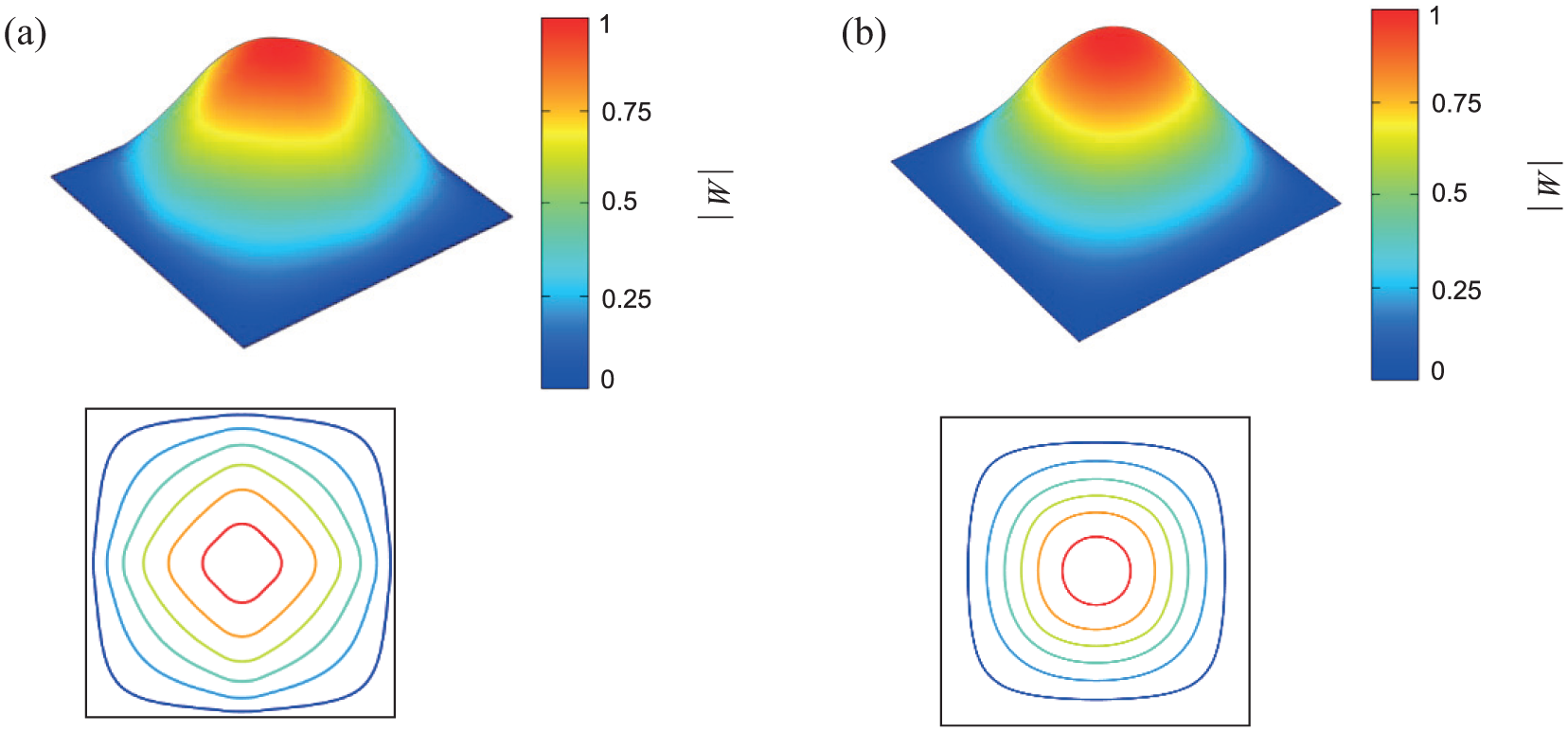
The wave modes of the proposed and conventional metamaterials corresponding to the upper bounding frequencies are shown in Figure 6. The shape of the wave modes is quite different. The deformation of cell with cross-shape patch is cross-shape as well, while the deformation of cell with square patch is more close to a circle shape. However, they still demonstrate some common features. Specifically, the motions of the two cells, both dipole, that is, the center region and the corner region, move oppositely.
Normalized wave modes of the (a) proposed and (b) conventional acoustic metamaterials at the upper bounding frequencies.
Also, the cross-shape patch can more strongly affect the deformation of substrate plate. Then, much more mechanical energy will be transformed into electrical energy, which enhances the local resonance of shunting circuit. For that reason, the cross-shape patches can broaden the bandwidth of the acoustic metamaterials.
Analyses of effective modulus
The variation of effective elastic modulus with frequency is plotted in Figure 7. A zone of NM is observed, whose range is from
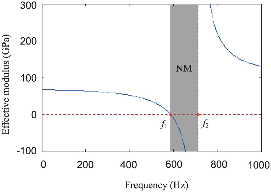
Variation of effective modulus with frequency.
Comparing the NM zone with the band-gap zone, one can find that the band gap is located within the NM zone, but not identical. Indeed, the band gap is induced by negative effective modulus, but not merely determined by it.
The variation of effective Poisson’s ratio with frequency is illustrated in Figure 8. Also, a zone of negative Poisson’s ratio (NP) is observed, whose range is from
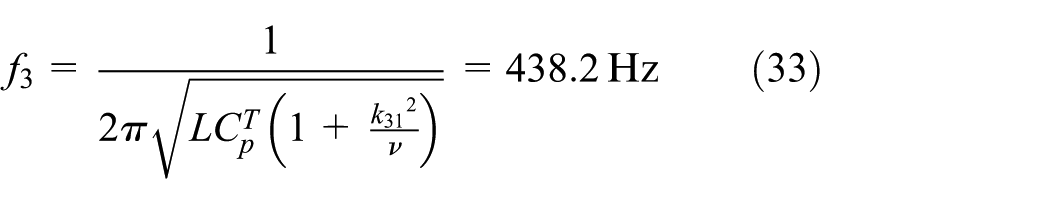

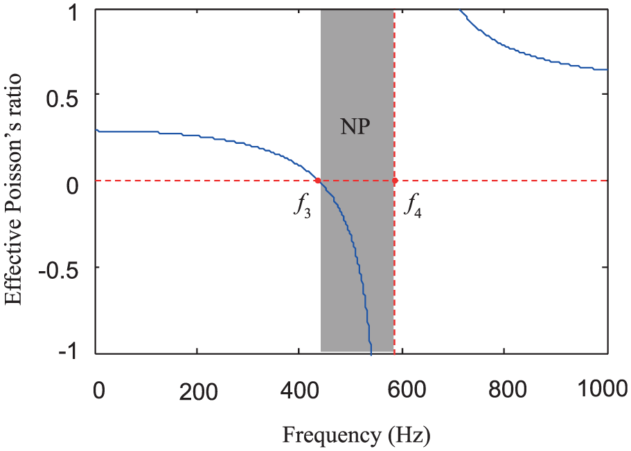
Variation of effective Poisson’s ratio with frequency.
The piezoelectric patch will simultaneously expand/contract in the x-axis and y-axis directions when applying voltage on the electrodes, so the NP ratio can be generated easily even without resonance of the external circuits.
Parameter analyses
The variations of bandwidth with the size of piezoelectric patch are plotted in Figure 9. One can find that the bandwidths of the proposed and conventional acoustic metamaterials both increase with the increase in the piezo-size. Nevertheless, the bandwidth of the proposed one is always much larger than that of the conventional one.
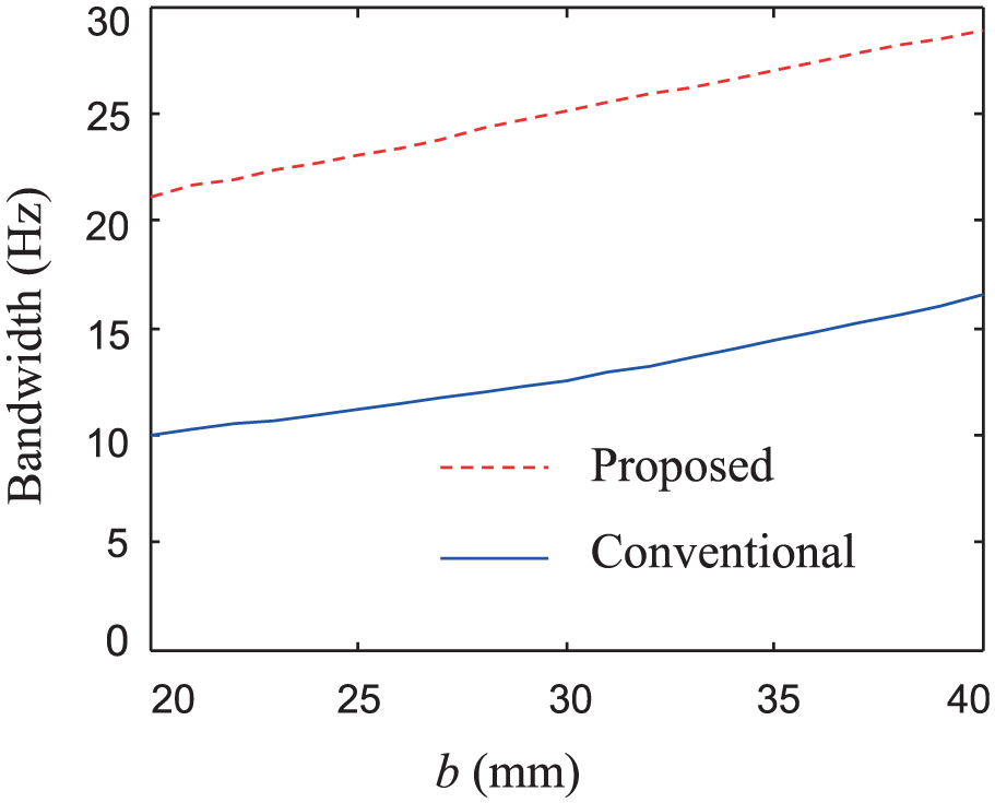
Variations of bandwidth with the dimension of piezo-patch.
Also, the variations of bandwidth with the shunting inductance are plotted in Figure 10. It is observed that the bandwidths of the proposed and conventional acoustic metamaterials both decrease with the increase in inductance. Similarly, the bandwidth of the proposed one is always much larger than that of the conventional one.
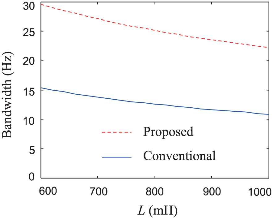
Variations of bandwidth with the shunting inductance.
Hence, the proposed scheme is always much better than the conventional one without connection of piezo-size and shunting inductance.
Transmission properties of finite periods
FE model built in COMSOL
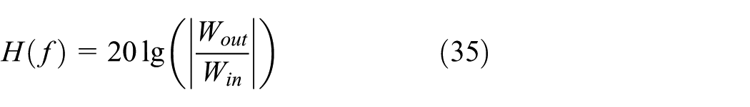
In order to validate the theoretical results, three-dimensional finite models are built in COMSOL, which is a well-established commercial FE software, for numerical simulations. The models are composed of 10 × 10 periods as shown in Figure 11 and are excited at one side with a unit area force Fz = 1 N/m2. The frequency responses of the models are calculated. The average out-plane displacements of the input and output sides are picked up as Win and Wout, so the transmission properties are defined as follows
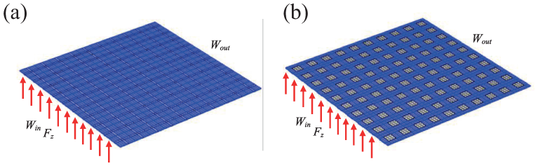
Simulation model of the (a) proposed and (b) conventional acoustic metamaterials.
Transmission properties
The simulated transmission properties are plotted in Figure 12. Compared with the shunting circuits without inductance (L = 0), the resonant circuits (L = 800 mH) do produce an AZ in both two metamaterials, whose locations are in accordance with the band locations. The widths of the AZ agree well with the bandwidths as well. The simulation results also prove that the proposed metamaterial can generate a wider band gap than the conventional one. Therefore, the cross-shape patches are better than the conventional square patches.
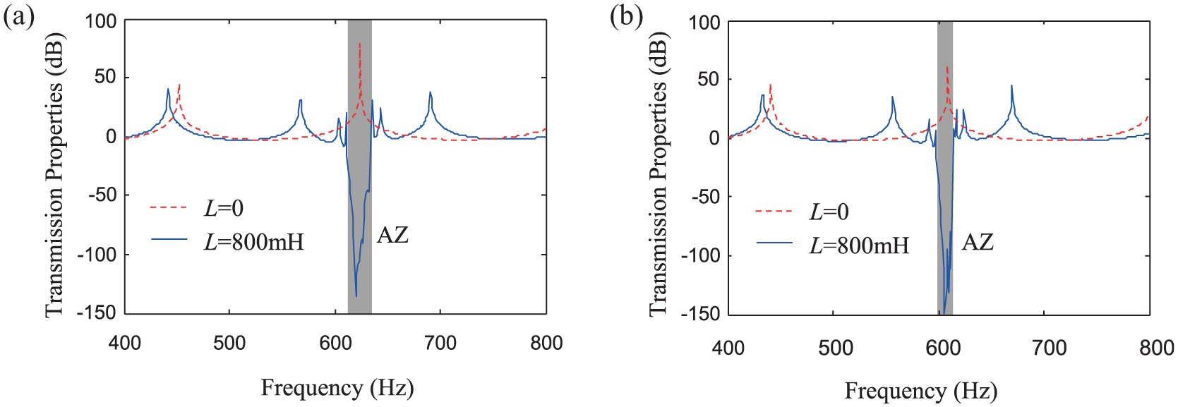
Transmission properties of the (a) proposed and (b) conventional acoustic metamaterials.
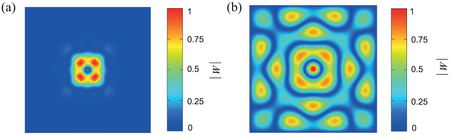
In order to get an intuitive sense of the attenuation effect of the band gap, we substitute a concentrated force excitation (Fz = 0.2 N) in the center of FE model for the area force excitation on the side (refer to Figure 11) and obtain the resulting transmission of the disturbance within the band gap. Figure 13(a) shows graphically the simulation result of disturbance transmission in the proposed acoustic metamaterials, whose excitation frequency is 620 Hz. For comparison, the acoustic metamaterials without shunting inductance are illustrated in Figure 13(b) as well. Similarly, Figure 14(a) demonstrates the simulation result of disturbance transmission in the conventional acoustic metamaterials, whose excitation frequency is 608 Hz. Also, the acoustic metamaterials without shunting inductance are illustrated in Figure 14(b) for comparison. Obviously, disturbances within the band frequencies can be completely localized around the excitation source, while the disturbances can propagate in the acoustic metamaterials without local resonances. It is proved that the wave propagation in the band gap can be effectively decayed by local resonances. Also, the results indicate that the metamaterials may be applied to vibration isolation.

Normalized disturbance transmission of the proposed metamaterials within the band frequencies (a) with and (b) without shunting inductance.
Normalized disturbance transmission of the conventional metamaterials within the band frequencies (a) with and (b) without shunting inductance.
Conclusion
In this article, cross-shape piezoelectric patches were originally proposed to improve the band-gap properties of acoustic metamaterials with shunting circuits. For comparison, a conventional metamaterial with square patches were analyzed as well. First of all, the dispersion curves were examined, which demonstrated that a locally resonant band gap was produced by the resonant shunting circuits. However, the bandwidth of the metamaterial with cross-shape piezos is much wider than that with square ones, about twice. Also, the examination of wave modes showed that the cell deformations corresponding to the lower and upper bounding frequencies are rather different. In fact, this is the reason for different bandwidths, though the effective area of the cross-shape and square patches is the same. The inherent capacitance of the piezoelectric patch is not only related to its size but also determined by its boundary conditions. Therefore, the band-gap width and location of the two metamaterials are different even with the same shunting circuits. Also, NM and NP were observed around the resonant frequencies. The simulation of transmission properties in COMSOL validated the theoretical band-gap predictions. An obvious AZ was observed, whose width and location were matching well with those of the band gap. The propagation of waves located within the band-gap frequency regime was decayed significantly, which demonstrated potential applications in vibration isolation.
Footnotes
Declaration of conflicting interests
The author(s) declared no potential conflicts of interest with respect to the research, authorship, and/or publication of this article.
Funding
The author(s) disclosed receipt of the following financial support for the research, authorship, and/or publication of this article: This work was supported by the National Natural Science Foundation of China (grant no. 11702306).