






Abstract
In this article, a new concept of two-dimensional modular deployable truss structure is proposed. To eliminate additional needs of containment mechanism, the proposed deployable structure is designed to have bistable characteristics so that it can stay robust both in the stowed and deployed states. The deployment of each module is triggered by the actuation of shape memory alloys. Static and dynamic models of the proposed deployable structure are established to analyze the characteristics and behavior of the system. The packaging ratio of the proposed structure is analyzed in terms of the design parameters. The results of static and packaging efficiency analysis show that the proposed concept has operational flexibility and high packaging efficiency. Verification of the dynamic model is performed based on a comparison of the response of the dynamic model and the actual deployment process of an experimental model; the deployment process is captured using a stereo pattern recognition camera system. It is shown that the established dynamic model can accurately describe the deployment behavior of the proposed structure.
Introduction
A deployable structure is capable of transforming its compactly stowed configuration into an operational configuration while deploying in a specific direction. This characteristic has advantages for storage and transportation (Fenci and Currie, 2017). This structural concept has been investigated for space applications and has been considered as a solution to overcome the limited transporting capability of launch vehicles and the issues related to the construction of large structures in space: transportation, assembly, and maintenance (Guest, 1994). Numerous deployable concepts have been suggested and developed for space applications, such as supporting structures for large solar arrays (Craighead et al., 1982; Warden, 1987), a deployable reflector concept for solid space antennas (Guest and Pellegrino, 1996), a truss structure for a deployable mesh antenna (Thomson, 2002).
A deployable structural system for space application must be simple, lightweight, and able to withstand the high loading condition during the launching phase while assuring low cost (Miyazaki, 2018). Deployable structures also need their own deployment mechanisms to change from the stowed state to the operational state. The most common deployment mechanism employs elastic restoring force as the driving force for deployment. This has been widely used for deploying solar arrays and antennas in satellites since the deployment process is both reliable and simple (Pellegrino, 2014). This mechanism, however, additionally requires hold and release devices for holding the structure under the high acoustic loading condition during the launching phase and releasing the structure to make it operate. The existence of an additional containment mechanism may increase the complexity of the system, which can considerably increase the cost.
One solution for these issues is to employ bistability on the deployable structure. The most common type of deployable structure with bistable characteristics is a boom structure, which has a shape similar to that of tape measures. Daton-Lovett et al. (2000) first proposed this idea, called bistable reeled composite (BRC), to overcome the limitations of the fundamental deployable boom strut, such as the need for considerable restraint and relatively heavy and complex mechanisms. The fundamental characteristics of this structure have been investigated by Iqbal et al. (2000) and Lei and Yao (2010). This deployable boom concept has been researched for the various uses, such as the supporting structure for flexible solar arrays and solar sails (Fernandez et al., 2014).
Although this type of bistable deployable structure has the advantage that a containment mechanism is unnecessary since both the deployed and rolled configurations are stable, this structural concept still has the limitation that the characteristics of the structure are not available to be changed after fabricating the material of the structure, and the structural shape itself is limited as tubular. This indicates that the concept may not be suitable for applications that need operational flexibility or tunable characteristics of the system.
This article proposes a new concept of two-dimensional (2D) deployable truss structure that has bistable characteristics. The structure is designed to have bistability to eliminate additional needs of containment mechanism. In addition, the proposed structure has operational flexibility as it is designed to change its system characteristics during operation by shifting the positions of the specific components inside. Since the structural concept described in this article is a unit structure, various configurations of the deployable structure can be constructed by changing the connecting direction of each unit or varying the design parameters of a single unit. The deployment of the proposed structure is performed through the snap-through phenomenon, which is the fundamental characteristic of bistable structures. To change the state of the bistable structure from the first stable state to the other, we use a shape memory alloy (SMA), which has been verified to be suitable for aerospace application (Hartl and Lagoudas, 2007). Because of its mechanical simplicity and reliability, the SMA actuator ensures additional reduction in the cost, size, and complexity of the system (Jani et al., 2014). The SMA actuator has been considered as a promising actuator for the system in various applications in aerospace engineering, including vibration isolating systems (Jeong et al., 2014; Khan et al., 2004; Lagoudas et al., 2004) and actuating devices for deployment systems (Huang et al., 1996; Lan et al., 2007).
Design and characteristics analysis of the proposed structure
Conceptual design and deployment
The proposed deployable truss structure is composed of two bistable components. Basically, each bistable component consists of two main-supports and two sub-supports. All the supports are considered as rigid bars in this study. The elastic component (e.g. extension spring) is connected between the main- and sub-support by crossing the axis of structural symmetry to generate the bistable characteristics to the proposed deployable structure. All the supports are connected to each other with frictionless joints; thus, the entire structure has a similar shape with a four-bar linkage mechanism.
Figure 1 shows the stowed and deployed configuration of a single unit of the proposed deployable structure. An SMA spring is used as the actuator for deploying the proposed deployable structure. The SMA spring is installed between the main–main (M-M) joint and the sub–sub (S-S) joint, which connect two main-supports and two sub-supports, respectively.

Stowed and deployed configuration of a single unit of the proposed structure.
The important parameters determining the area of the proposed structure are the length of the main-support and the angle between two main-supports in the deployed configuration. In the deployed configuration, the main-support and sub-support meet with a right angle to sustain its shape and secure the effective area of the deployable structure.
The deployment of the proposed structure is conducted using the shape-restoring effect of the SMA spring. In the stowed state, the SMA spring is attached to the structure with the extended state. By heating, the SMA spring recovers its original shape, which causes the actuating force on the proposed structure. If the restoring force is larger than the critical load, which is required for generating the snap-through behavior, the deployment proceeds. Figure 2 presents the entire deployment process described above (See also Supplemental video).

Deployment sequence of the proposed structure.
The connection points of the elastic component may have distances from the joints as shown in the Figure 3. The ratio between the offset distance and the length of the support corresponding to the relevant connection point is defined as the off-axis ratio. The off-axis ratio corresponding main-support and sub-support is expressed with parameters p and q respectively.

Single bistable component of the proposed structure.
Establishing the static model of the structure and stability analysis
The proposed deployable truss structure has two bistable components, and the structure can stay robust in both stowed and deployed configurations because of its bistability. The deployment process of the proposed structural concept is the same as the state changing of the bistable system, which is conducted by applying external work on the structure. Therefore, an analysis of the overall system characteristics, such as critical load for generating snap-through behavior as well as stable and unstable states of the proposed system should be carried out for successful deployment. In this section, the static model of a single bistable component is established to conduct an analysis of the effect of the off-axis ratio, which is defined from the previous section, on the system characteristics.
Figure 4 shows the simplified model of the single bistable component and all the notations used to derive the static model of single bistable component. The following assumptions are used to establish the static model of the structure. The elastic component is assumed to have linear behavior as the extension spring. Also, the shape restoring force of the SMA spring is applied to the structure as the external force, and it always follows the direction of the line that connects the M-M joint and S-S joint. The remaining structural part after the S-S joint is neglected since it does not affect the static behavior of the system. The effective length of the sub-support is used to derive the equation, instead of the length of the sub-support.

Simplified model of the single bistable component and notations.
Figure 5 shows the free-body diagram for the joint a and each support. The equation of force and moment equilibrium for joint a and each support was set to derive the expression of the external force in terms of the angle between two sub-supports,
where
Here, k denotes the spring coefficient, and
Here,
By substituting equations (2) to (4) in equation (1), the external force to maintain a certain shape of the single bistable component can be expressed with all the necessary design parameters, such as the off-axis ratio, the lengths of the main- and sub-supports, and the variables that represent the angle between supports. Since all the supports are rigidly connected to each other, the angle between two main-supports,
By substituting equation (5) in equation (1), the external force can be expressed as the function of

Free-body diagram of joint a and supports of the single bistable component.
The values of the design parameters used to analyze the effect of the off-axis ratio on the system characteristics are listed in Table 1.
Values of design parameters.

Figure 6 shows the external force required to maintain a certain shape of the single bistable component with respect to the varying value of the single off-axis ratio, p only, while the value of q is restricted to the value of 0.2. Here, the overall tendency of the graph shows that the required external force increases as

Required force curve with respect to the angle between two sub-supports.
Figure 7 shows the potential energy of the system with respect to the angle between sub-supports under the same conditions as those used to analyze the critical load of the system. As the fundamental bistable system, the proposed structural concept has two stable states and one unstable state. The angle between two sub-supports to make the structure have a second stable state decreases as the off-axis ratio increases.

Potential energy of the system with respect to the angle between two sub-supports.
Note that the off-axis ratio should have an upper limit because there would be cases in which the angle between two sub-supports for the second stable configuration would be smaller than the designed angle in the deployed configuration. This means that the structure may have a stable state before reaching the designed deployed configuration. The value of
Value of

Note: The shaded values imply the cases that the second stable state appears before reaching the designed deployed configuration (at θsf= 240°).
Packaging efficiency of the proposed structure
The packaging efficiency of the deployable structure is the important criteria that evaluate the efficiency of the deployable structure. In this section, the packaging efficiency is considered as the ratio between the effective area of the structure in the deployed configuration and the effective area of the structure in the stowed configuration. Since the structure proposed in this article has two symmetric bistable components and the structural behavior of each component during deployment is the same, the packaging ratio of the single bistable component can represent the packaging ratio of a single unit.
A non-dimensional parameter is proposed to express the packaging ratio of the structure since the proposed deployable truss structure is scalable
where
Figure 8 shows the configuration of the single bistable component in the stowed state and an enlarged view around two M-S joints. Assuming that the single bistable component is completely folded in the stowed state, the distance between two M-S joints can be approximated as the width of the main-support,

Stowed configuration of the single bistable component (top) and enlarged view around the joint (bottom).
The packaging ratio in this study is limited in 2D aspects since all the behavior of the proposed structure is considered only in-plane. Figure 9 shows the simplified model that indicates the effective area of the single bistable component in both configurations.

Simplified model which indicates the effective area of each state and notations.
Considering the geometrical relationship of the structure, each parameter is expressed using non-dimensional parameters as follows
Here,
while the area of the single bistable component in the deployed configuration,
Therefore, the packaging ratio of the proposed deployable truss structure is obtained as
By assuming that the proposed structure is compactly folded under the stowed condition,
By conducting the linearization process, the initial angle between both main-supports and sub-supports is expressed with the combination of the functions of
where
Using the above expression, the analysis of the effects of the variables on the packaging ratio is conducted.
Figure 10 shows the tendency of each function that is used to describe the packaging ratio by varying the corresponding variables. The left graph of Figure 10 indicates the values of

(a) Function of
Dynamic model of the proposed structure
Establishment and evaluation of the dynamic model
Establishing dynamic model of the proposed structure
In this section, the dynamic model of the single bistable component is established based on the four-bar linkage approach (Tang, 2006). While setting up the equation of motion for the single bistable component, the following are assumed to simplify the modeling process: the effect of gravity is neglected, and the elastic component is a linear extension spring. The structural effect of the SMA spring on the system is neglected, so the behavior of the SMA spring is considered as only the external force, which varies according to the time and length of it. The shape restoring force from the SMA spring only applies in the direction of the line that connects an M-M joint and an S-S joint.
Figure 11 presents the simplified line model of the single bistable component, numbering of each support and joint, and the parameters used to derive the equation of motion. The main-support 3 is fixed on the ground, and the origin of the coordinate is placed at the joint c. The angle between the x-axis and each support is denoted by
where T is the kinetic energy of the system, and V is the potential energy of the system. As we assumed that one main-support is fixed on the ground, and each support is rigidly connected to each other, the single bistable component has only one-degree of freedom. Thus, the angular variables,

Simplified line model of the single bistable component; numbering of each support and joints and the parameters.
Two equations regarding angular variables are established from the position of the joint a
From the above equations, the equation between two angular variables,
Equation (18) is the form of Freudenstein equation so that the angular variable,
Here, the meaning of (±) is that the structure can have two different configurations with respect to a certain value of
Thus, both
where
The potential energy of the system can be expressed with the simple function that describes the potential energy of the normal extension spring as
where
where
The kinetic energy of the proposed single bistable structure can be derived as
where
M denotes the mass of the main-support, and m means the mass of the sub-support. By substituting equations (22) and (25) in equation (21), we can get the equation of motion of the single bistable component as follows
where
Here,
The generalized force,

Simplified line model of the single bistable component indicating the direction of the external force.
According to the assumption that the shape restoring force from the SMA spring is applied only in the direction of the line connecting an M-M joint and an S-S joint, the virtual work done by the external force can be described as
Finally, the generalized force applied to
By substituting all the necessary terms in equation (21), we can obtain the equation of motion that describes the behavior of the single bistable component of proposed structural concept.
Comparison with static models
To verify the established equation of motion, a comparison between the response of the system with the static and dynamic model was performed. First, the angular response between sub-supports was obtained through the equation of motion for the case when the applied external force level is not enough to generate deployment.
The specifications of the verification model used in the comparative evaluation are summarized in Table 3. The numerical values of the verification model were substituted into the equation of motion, and the solution of the equation was obtained using the ordinary differential equation (ODE) solver in MATLAB.
Specifications used for the comparative evaluation.
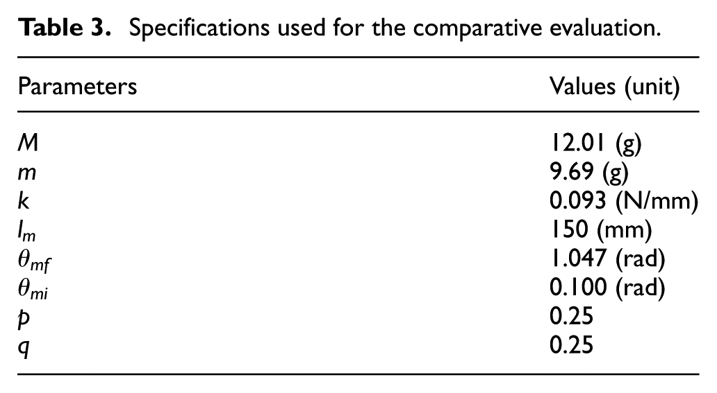
Figure 13(a) shows the force equilibrium curve for the static model. The critical load of the structure for the snap-through is about 3.27 N. When the force of 2 N is applied to the structure, the verification model has the equilibrium state when the angle between two sub-supports is of 0.810 rad. Figure 13(b) shows the change in the angle between two sub-supports when a ramp load reaching 2 N after 50 s is applied to the structure to simulate a gradual increase in the external force. In this case, the maximum magnitude of the external force applied to the structure is smaller than the critical load. Therefore, deployment cannot occur, and the structure converges to a certain configuration. The angle between two sub-supports at the converged configuration was about 0.810 rad, which is exactly the same value obtained from the static model. This comparison analysis confirmed that the dynamic model can accurately describe the response of the proposed structure in the case of non-deployment.

(a) Force equilibrium curve for the static model when
To analyze the structural response when deployment has occurred, the magnitude of the ramp load applied to the structure was increased to 3.3 N. Figure 14(a) shows the change in the angle between the main-supports during the deployment. Figure 14(b) shows an enlarged view of the response curve of the structure in the vicinity of the completion of the deployment. As seen in the result of the analysis on the angle between the main-supports of the structure, the equation of motion of the system can describe the motion of the proposed structure starting from the stowed configuration to the deployed configuration.

(a) Response of the dynamic model when ramp load of 3.3 N is applied to the structure (left). (b) Enlarged graph at the completion moment of the deployment (right).
Evaluation of dynamic model through comparison with experimental model
Experimental modeling of shape restoring force
In this section, we attempt to evaluate the accuracy of the dynamic model by comparing the response with the actual motion of an experimental model. To simulate the force applied to the structure by an SMA spring, the magnitude of the shape restoring force according to the length of the SMA spring was measured through experiments.
Figure 15 shows the experimental equipment and configuration for measuring the force of the SMA spring. The SMA spring was connected to a three-axis stage with a uniaxial force sensor, which can fix one end of the spring and move the other end in the longitudinal direction. A Flexinol® spring with a 40-coil model of DYNALLOY Co., Ltd. was used, and an ICP Force sensor 208C01 model was used to measure the force.

Experimental setup for measuring the force of the SMA spring.
The experiment was performed to obtain the time history of shape restoring force within the operation range of SMA spring. Since the simultaneous measurement of force in time and displacement is complex, the entire measurement of the force was conducted with the combination of repetitive experiments with the length-fixed condition. The single experiment was performed with the following procedure: initially, the SMA spring is pre-strained to a certain length, while both ends of SMA spring are fixed. Then, the heat is applied to the SMA spring through ohmic heating. The pulling force of the SMA spring is measured by the force sensor. After completing the single experiment, the pre-strained length is changed and the same procedure of measurement is conducted to measure the force of the SMA spring with different length condition. Under the consideration of the available operation range of the SMA spring used in the experiment, the shape restoring force was measured with time while the initial length of the SMA spring was increased from 80 to 240 mm at intervals of 12.5 mm. The experiment was designed to apply a constant voltage of 4 V to the SMA spring. Each of the experiment was performed under the same temperature condition (295 K).
Figures 16 and 17 show the shape restoring force according to the length of the SMA spring. As a result of the experiment, the magnitude of the shape restoring force increased as the temperature of the SMA spring gradually increased. Eventually, the restoring force converged to a constant value after a certain period of time. In addition, the time to reach the maximum restoring force tended to be delayed with increasing initial length of the SMA spring. The maximum magnitude of the shape restoring force tended to increase with extension of the initial length as well.

Measured data of the shape restoring force with respect to the varying value of initial length (80–155 mm).

Measured data of the shape restoring force with respect to the varying value of initial length (167.5–242.5 mm).
The dynamic model for comparative analysis was established by substituting the restoring force data into the external force term in the equation of motion. To measure the motion of the proposed structural concept, the experimental model was constructed. The evaluation of the dynamic model was conducted by comparing the responses of the experimental model and the dynamic model. The comparative evaluation was conducted under two different conditions. First, the SMA spring was assumed to generate the maximum force for each length; in other words, the deployment process is started after sufficient time has passed since heat was applied to the SMA spring. Second, the restoring force of the SMA spring has a time-varying value; that is, deployment was assumed to be started immediately after heat was applied to the SMA spring.
The functions of the shape restoring force were extracted from the experimental results in two different ways to satisfy the different loading conditions. By following the first condition of the two described above, the function of the restoring force was obtained by gathering the maximum value of the restoring force data from every result of previous measurements.
Figure 18 shows the maximum shape restoring force of the SMA spring with respect to its length. By fitting the indicated data with the rational function, the restoring force function can be expressed with the length of the SMA spring as

Maximum shape restoring force for each length of the SMA spring.
Figure 19 shows the three-dimensional data of time-length-restoring force of the SMA spring. Since the time history of the restoring force for each length was measured under the discrete length conditions with intervals of 12.5 mm, the magnitude of the force with respect to the length values between the measurement lengths was approximated using a 2D interpolation method.

Time–length–shape restoring force plot.
Capturing motion of the experimental model using stereo pattern recognition camera and comparison with dynamic model
The experimental model of the proposed structure was constructed to compare the behavior of the dynamic model and the actual model. For motion capture, a stereo pattern recognition (SPR) camera system was used as shown in Figure 20.

Experimental setup for capturing the motion of the single bistable component.
The markers were attached to each joint, and a voltage of 4 V was applied to the SMA springs. The experiment was conducted in two different cases as set in the previous section. To realize the first condition, the experimental model was set to be deployed after 10 s since the voltage of 4 V was applied to the SMA spring. The motion capture system was set to start measurement immediately after deployment started. For the second case, the experimental model started to deploy immediately after the voltage of 4 V was applied to the SMA spring, without any additional time-delay setup.
The position of each marker was measured with variation of time; finally, the angle between two main-supports was calculated from the time-history data of the position. The dimensions of the experimental model are presented in Table 4.
Specifications of the experimental model.
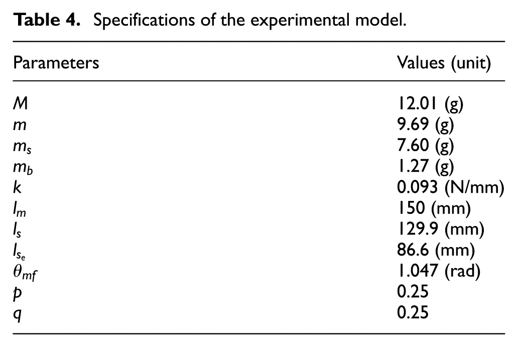
Since the mass of the bearing and shaft used to construct the experimental model is not negligible, the dynamic model should be modified by adding additional mass terms. As the mass of the shaft,
Figure 21 shows a comparison of the results obtained for the first experiment condition in terms of the angles between the main-supports measured from the experimental model and simulated from the dynamic model. In the case of the experimental model, deployment was completed in 0.108 s. In the case of the dynamic model, deployment was completed in 0.106 s, which is close enough to the result from the experimental model. Also, by comparing the behavior of the structure in the deployment process, it can be concluded that the derived dynamic model precisely simulates the motion of the actual structure.

Comparison results of the system behavior under the condition of sudden deployment.
Under the second experiment condition, both the motion of the experimental model and the dynamic model were compared from the moment when the voltage was applied to the SMA spring to the completion of deployment.
Figure 22 presents a comparison of the results of the angle between the main-supports measured from the experimental model and simulated from the dynamic model. For the dynamic model, deployment took 4.126 s to be completed, which showed the value of 4.696 s in the case of the experimental model. Since the semi-empirical model derived from this study does not consider the effects of friction and damping, there would be some differences between the results obtained from the dynamic model and the experimental model around the vicinity of the starting and completion points of deployment. Even though there are slight differences in the behavior of the two models, it is concluded that the established dynamic model can accurately predict the deployment behavior and the completion time of deployment.

Comparison results of the system behavior under the condition of steady deployment.
Conclusion
In this study, a new concept of a deployable truss structure was proposed. The proposed deployable structure contains two bistable component, which consists of four rigid supports, one elastic component, and an SMA spring as the actuator of the proposed system. The elastic component is asymmetrically attached to the supports so that the system characteristic can be adjusted without changing the main configurations. To analyze the changes of characteristics with respect to the connecting points of the elastic component, the off-axis ratio was defined in this study.
The static model of the proposed structural design was established for the purpose of analyzing the critical load and stability of the system. It was confirmed that the critical load to cause deployment decreases as the off-axis ratio increases. From the result of stability analysis, the upper limits of the off-axis ratio should be considered in the design phase because the higher value of the off-axis ratio might make the proposed structure have a second stable state before it reaches the designed deployed configuration.
The packaging ratio of the proposed deployable structure was analyzed in this study. The non-dimensional parameter, which is defined as the ratio between the length and width of the main-support, was used to derive the packaging ratio of the structure. By linearizing the derived packaging ratio, the packaging ratio of the structure was described as the multiplication of two independent functions, the function of the angle between two main-supports in the deployed configuration and the function of the non-dimensional parameters. It was concluded that, to make the proposed structure have a high packaging ratio, the width of the supports should be thin enough in comparison to the length of the support.
The dynamic model of the proposed structure was established for the purpose of analyzing the behavior of the structure during deployment. To apply the shape restoring force of the SMA spring to the established dynamic model, a force measurement experiment was conducted with respect to the initial length of the SMA spring. The experimental model of the proposed structure was constructed to evaluate the accuracy of the established dynamic model by comparing the response of the structure when the shape restoring force is applied to the structure. The deployment behavior of the experimental model was captured using a stereo pattern recognition camera system. Based on a comparison of the results obtained from the dynamic model and experimental model, it was concluded that the established dynamic model can describe the behavior of the proposed deployable structure precisely. Using the dynamic model that was established in this article, further research on the deployment behavior of the proposed structure can be conducted with various types of actuators that can be substituted for the SMA spring.
Footnotes
Declaration of conflicting interests
The author(s) declared no potential conflicts of interest with respect to the research, authorship, and/or publication of this article.
Funding
The author(s) disclosed receipt of the following financial support for the research, authorship, and/or publication of this article: This research was supported by the National Research Foundation of Korea(NRF) grant funded by the Korea government(MSIT) (2018M1A3A3A02065888).

Supplemental Material
Supplemental video for this article is available online.
References
Supplementary Material
Please find the following supplemental material available below.
For Open Access articles published under a Creative Commons License, all supplemental material carries the same license as the article it is associated with.
For non-Open Access articles published, all supplemental material carries a non-exclusive license, and permission requests for re-use of supplemental material or any part of supplemental material shall be sent directly to the copyright owner as specified in the copyright notice associated with the article.
