
Abstract
Based on magnetorheological fluid, magnetorheological brake can exhibit promising characteristics in haptics such as intrinsic passiveness and high torque density. The main difficulty in applying magnetorheological brake lies in the magnetic hysteresis. To deal with the magnetic hysteresis, a magnetorheological brake was combined with a micromotor to construct a hybrid actuator in this article. A novel hollowed multi-drum architecture was adopted for the brake so that the micromotor could be placed inside the brake to obtain a compact structure. The brake produced the maximum torque of 1263.39 mN m with 40 mm diameter and 28 mm length. Through the closed-loop control, no obvious hysteresis loop was observed in the hybrid actuator current–torque figure. The maximum difference between the forward and backward torque was reduced from 7.2% to 1.94% of the total torque range. The dynamic range was increased from 41.17 to 45.42 dB. Furthermore, the experimental results proved that the hybrid actuator could track the reference signals more accurately than the brake.
Keywords
1. Introduction
Haptic device is a type of interface that needs to transmit haptic stimuli between user and virtual or remote environment. With precisely controlled force/torque exerted on user’s body (such as finger, hand, or arm), subtle object details can be perceived and a sense of immersion can be constructed. As an important part of haptic device, actuator influences the stability of haptic system and the quality of immersion. Generally, actuators for haptics mainly involve direct current (DC) motors, pneumatic actuators, and magnetorheological (MR) brakes (Blake and Gurocak, 2009; Bouzit et al., 2002; Endo et al., 2011; Qin et al., 2015; Senkal and Gurocak, 2010). The most common actuation methods in haptic devices are DC motors. They have features in terms of fast response, good controllability, and various haptic patterns, but low torque density, relatively high power consumption, and potential stability issues in interacting with stiff objects. Pneumatic actuators are popular for applications which need high power-to-weight ratio (Gupta and O’Malley, 2006). They can provide large force/torque and good adaptability. But they have problems in terms of slow response and low control accuracy. MR brakes, based on the rheological effect of MR fluids, are ideal choices for haptic devices because of their inherent passiveness, high torque density, and low power consumption. However, due to the magnetic hysteresis, the brake torque output cannot be accurately predicted, which deteriorates the immersion of haptic interaction.
One way to overcome this obstacle is to model the magnetic hysteresis directly. A famous hysteresis modeling method for intelligent material is the Preisach model (Adly et al., 1991; Mittal and Menq, 2000). In the model, the hysteresis is modeled as the weighted sum of all impact factors. Although it has been widely accepted and studied, it suffers from model identification problems. Furthermore, its inverse model cannot be obtained analytically, which brings difficulties in its application in a control system. There are some attempts to build the inverse Preisach models (Xiao and Li, 2013a, 2013b). However, these models need large computing and storage resources. The Prandtl–Ishlinskii (PI) and Krasnoselskii–Pokrovskii (KP) models (Qin et al., 2013; Zhang et al., 2012) are other two hysteresis modeling methods. Although the inverse model can be obtained easily, the PI model cannot exhibit the asymmetric hysteresis loop. The KP model also needs intensive computing resources. An et al. presented a nonlinear model for MR actuators. The model takes both the hysteresis of the ferromagnetic material and the nonlinear Bingham model of the MR fluid into consideration (An and Kwon, 2003). The Hodgdon’s model is adopted as the hysteresis model because it gives a good prediction. Its feasibility as a torque estimator was demonstrated through comparing with the experimental results. The Jiles–Atherton model was adopted to introduce the hysteresis phenomenon of the MR clutch (Jedryczka et al., 2009). The magnetization of this model is divided into two parts: the reversible part and the irreversible part. Performed experiments and simulations showed good concordance between the calculated and measured data. Liu et al. (2006) showed a sub-hysteresis model to describe the hysteresis behavior of the MR brake. To identify the model parameters, many tests must be carried out under different current conditions. The error between the predicted and measured results reached 5%. Yadmellat et al. presented an adaptive model for the MR actuator (Yadmellat and Kermani, 2014). In order to represent the hysteresis of magnetic circuit, the polynomial approximation method was used in this model. The experiments indicated the adaptive model could predict the behavior of the MR actuator more precisely than the Preisach model. Neural networks (Najmaei et al., 2015a; Zakerzadeh et al., 2011) are also efficient approaches in the hysteresis modeling. Other approaches include the resistor–capacitor operator-based hysteresis modeling (Bai et al., 2019) and shape function– and memory mechanism–based hysteresis modeling (Chen et al., 2018).
Except for direct hysteresis modeling, there are some magnetic field–based ways to overcome this obstacle. In order to reduce the hysteresis effect, Gonenc and Gurocak (2012) placed a hall sensor in the brake. The internal magnetic field measured by the sensor was feedback signals for the closed-loop control. Similarly, Li et al. (2015) presented a closed-loop field-programmable gate array (FPGA)-based control method to linearize the input–output relationship of the MR clutch. The hall sensors also provided the magnetic field feedback signals. The results showed that the MR clutch could track reference torque signals precisely. However, some issues must be considered in these magnetic field measurement methods. Since the hall sensor has relatively higher magnetic reluctance than the steel, it must be placed in a narrow channel where the flux has no alternative paths to pass through. Any escape of the flux will result in inaccurate measurements. Furthermore, the sensor is required to be placed close to the gap to avoid any influence of local effects.
Different from the direct hysteresis modeling methods and the magnetic field measurement ways, we combined an MR brake with a DC micromotor to construct a hybrid actuator to deal with the magnetic hysteresis. To keep powerful and compact, a novel hollowed multi-drum architecture was adopted for the brake and the micromotor could be placed inside the brake. With activating the micromotor through the closed-loop control, the hysteresis effect was significantly reduced and the dynamic range was increased.
The rest of this article is organized as follows: the hollowed multi-drum MR brake is designed and evaluated in section 2. The hybrid actuator is designed and evaluated in section 3. Conclusion is provided in section 4.
2. Hollowed multi-drum MR brake
In the hybrid actuators designed in Gonenc and Gurocak (2012) and Chapuis et al. (2007), the motors are located outside the brakes. Hybrid actuators of this kind are convenient in manufacturing and assembly. But they are too bulky for a portable device. To build a powerful and compact hybrid actuator, an ideal solution is to place the motor inside the brake.
2.1 Brake mechanical design
According to the architectures, MR brakes are divided into single-disk brake (Liu et al., 2006; Nam et al., 2008), multi-disk brake (Fauteux et al., 2009; Gudmundsson et al., 2010; Park et al., 2006), drum brake (Blake and Gurocak, 2009; Gonenc and Gurocak, 2012; Senkal and Gurocak, 2010), and T-shaped brake (Hung and Bok, 2012). Single-disk brake (Figure 1(a)) has one thin disk-shaped rotor. It is usually built with dimensions of large diameter and small length. The advantage of this architecture is that the structure is simple and compact. Multi-disk brake (Figure 1(b)) has several disk-shaped rotors and stators. It can generate N times the torque of single-disk brake, where N represents the number of disk-shaped rotors. Therefore, multi-disk brake is more compact than single-disk brake. Drum brake (Figure 1(c)) has a cylindrical rotor. It can generate promising torque when combined with the serpentine flux path technique, which forces the flux path across the fluid several times to activate more surface areas. T-shaped brake (Figure 1(d)) is a combination of disk and drum architectures. It has two coils located at two ends of the T-flange structure. Brake of this type is powerful since the inner and outer surface areas of the T-flange can be activated with two counter current. To place a motor inside a brake, the brake is required to have a hollowed casing to reserve space for the motor. The above architectures are inconvenient to construct a hollowed casing. In this article, we proposed a hollowed multi-drum structure which has several drums and a hollowed casing.
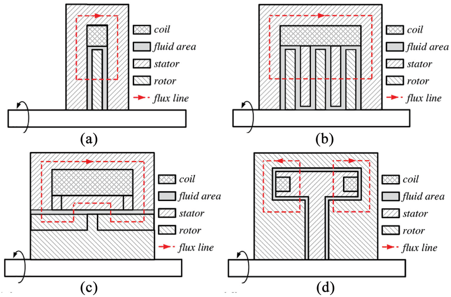
Major MR brake architectures: (a) single-disk brake, (b) multi-disk brake with three disk-shaped rotors, (c) drum brake with serpentine flux path, and (d) T-shaped brake.
The actual brake structure is shown in Figure 2. In this brake, copper and electrical pure iron (DT4C) are selected as the non-magnetic and magnetic materials, respectively. Copper parts mainly include a shaft, a copper casing, a drum holder, and a micromotor cover. Iron parts mainly include drums and a iron casing. The copper casing is screwed into the iron casing to form the outer boundary of the brake. Considering the torque requirement (1 N m), the brake has three drums. Two rotary drums are connected to the shaft by screws and have the same rotation with the shaft. One static drum is connected to the drum holder by screws. The drum holder is fixed to the iron casing, so that the static drum is fixed to the iron casing. Three drums and the iron casing form four fluid gaps, which are full of MR fluid. The drums, the iron casing, and the MR fluid in these gaps form a complete magnetic path. The coil, which is used to generate the magnetic field, is placed right next to the drum holder. The micromotor cover is fixed to the iron casing by screws. It is combined with the copper and iron casings to form a complete sealed casing. The sealed bearing (MR128ZZ, NSK) is used to support the shaft. From the perspective of fluid leakage prevention, conventional methods adopt O-rings (Senkal and Gurocak, 2009), separator rings (Shiao et al., 2016), or lip seal (Demersseman et al., 2008). These sealing methods may lead to increased off-state torque and fluid corrosion problems (Senkal and Gurocak, 2010). This brake uses the ferro-fluidic sealing method. The magnetic ring leans against the sealed bearing through a spacer ring. It generates the magnetic field across the ring gap, which can turn the leaking fluid into semi-solid state to prevent further leakage. Due to the absence of direct mechanical friction, this method reduces the brake off-state torque and has good sealing performance.
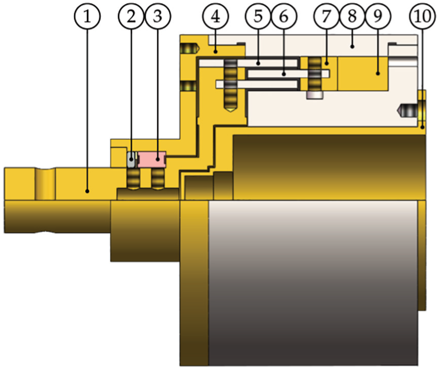
MR brake structure.
2.2 Brake optimization based on finite element analysis
An ideal brake is required to generate large torque in a small volume. The torque output of MR brake is proportional to the shear area and the shear stress. Larger shear area can be achieved via increasing the drum diameter and length, but this will increase the size of the brake. The shear stress is a function of the magnetic flux density, which is related to coil turns and current, and the thickness of the gap. The torque grows with increasing coil turns and current, while reducing the gap. However, increasing coil turns also leads to a large size, and large coil current is not desirable considering the brake heat dissipation. Manufacturing difficulty increases as the gap narrows. The general gap is 0.25–2 mm (Yoo and Wereley, 2002). It is also noteworthy that the saturation points of the materials on the flux path can affect the flux density and hence, the shear stress and the torque output. If the magnetic field is beyond the saturation points, the torque increase will be limited. MRF-122EG from Lord Corporation and DT4C are two materials on the flux path. According to the specifications of MRF-122EG, the saturation happens when the magnetic field reaches 250 kA/m, and the flux density corresponding to 250 kA/m is 0.7 T. Therefore, the MRF-122EG saturation point is chosen to be 250 kA/m and 0.7 T. Conservatively, according to the specifications of DT4C, the saturation happens at about 1000 A/m. The flux density corresponding to 1000 A/m is 1.5 T. Therefore, the DT4C saturation point is chosen to be 1000 A/m and 1.5 T. The B-H curves of the two materials are shown in Figure 3.
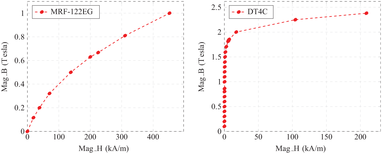
B-H curves of MRF-122EG and DT4C.
Taking into account the torque requirement, the general gap thickness, and the material saturation points, the brake was optimized via the Maxwell finite element analysis (FEA). First, a Maxwell two-dimensional (2D) design was inserted, and the magnetostatic-based solution type was selected. A geometric model was created with inputting the initial values of design variables. After assigning the materials, excitation, and the balloon boundaries, the solving loop was started to find the optimal design variables including the magnetomotive force and iron casing dimensions. It was assumed that all flux was kept inside the brake and the current density was uniform on the cross section of the coil. In the optimization, the Quasi Newton optimizer was selected. The optimization objectives were to maximize the braking torque to meet the torque requirement while keeping the brake volume as small as possible. The torque requirement was set as 1 N m. The inner diameter of the micromotor cover was set as 16 mm considering the torque requirement and the general hysteresis impact on torque output (Alkan et al., 2013; Gonenc and Gurocak, 2012; Najmaei et al., 2015b). The iterations were related to the initial values of the design variables. In this article, after 174 iterations, the optimal brake has dimensions of 40 mm outer diameter and 28 mm length. The inner radius for the small, medium, and large drums are 13.7, 15, and 16.3 mm, respectively. The drum length and thickness are 6 and 1 mm, respectively. The gap thickness is 0.3 mm. The coil has 298 turns of 0.25 mm diameter enameled copper wire. The FEA result under the magnetomotive force of 270 ampere-turns (At) is shown in Figure 4. As displayed in Figure 4, the maximum flux density on the iron path is about 1.5 T expect for the corner areas. The measurement of the field strength and the flux density over gaps are shown in Figure 5. The gap 1 (smallest gap) has the field strength of 246 kA/m and the flux density of 702 mT. Both MRF-122EG and DT4C reach their saturation points under the magnetomotive force of 270 At. The gaps 2, 3, and 4 have the field strength of 207, 181, and 158 kA/m and the flux density of 639, 589, and 540 mT, respectively.
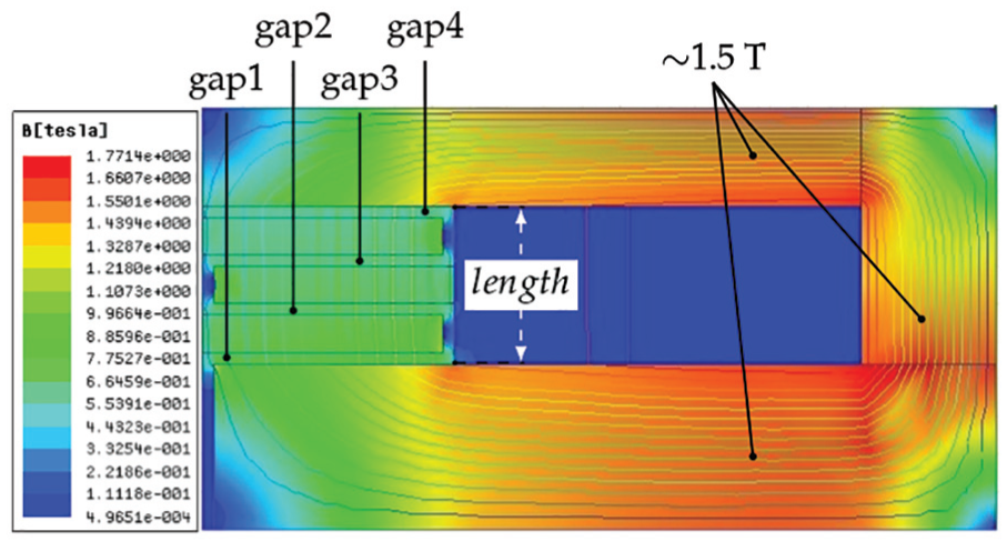
Result of finite element analysis.
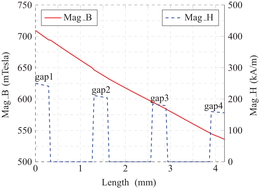
Flux density and field strength measured over gaps.
The brake prototype is displayed in Figure 6. Its details are shown in Table 1.
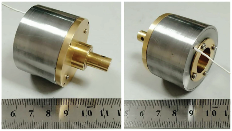
MR brake prototype.
Details of MR brake.

MR: magnetorheological.
2.3 Brake model
In this brake, the Bingham visco-plastic model is selected to describe the behavior of MR fluid. The total shear stress of MR fluid is related to the dynamic yield stress
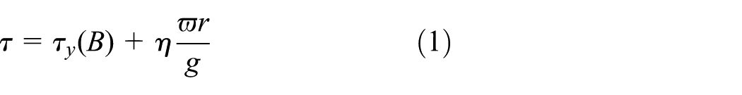
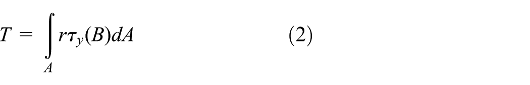
The braking torque T is obtained by the integral of the total shear stress on the active shear area A. The viscous torque is usually ignored due to the relatively low angular velocity of MR brake in haptic applications
Taking the smallest gap of this brake as an example, the calculation principle is described in Figure 7. In Figure 7,
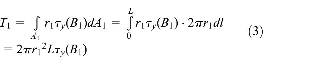
Therefore, the total torque output
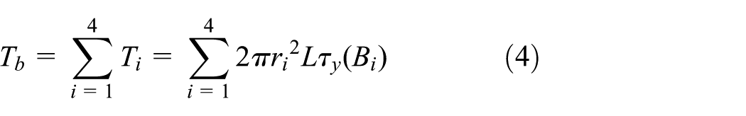
Braking torque calculation over smallest gap.

According to equation (4), this brake has the expected saturation torque of 1084.33 mN m at the current of about 0.9 A.
2.4 Brake evaluation
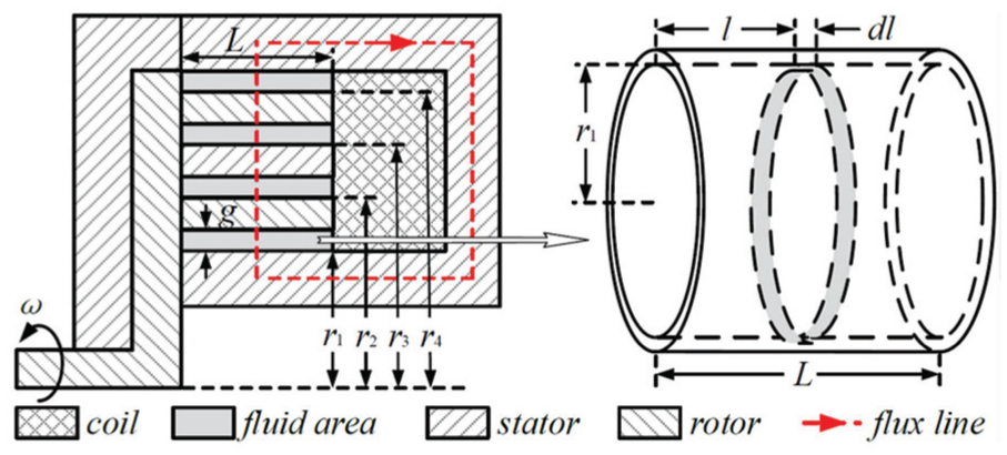
Generally, the torque-volume ratio, dynamic range, and time constant are three important parameters for a brake. The torque-volume ratio shows the powerfulness and compactness. The dynamic range and time constant show the controllability and reactivity, respectively. The parameters of this brake are evaluated on the experimental setup (shown in Figure 8). The drive motor combination (RE 40, Maxon), which has the nominal torque of about 5.8 N m and the nominal speed of about 40 r/min, is used to rotate the brake. The brake holder can fix the brake casing to the setup base. The brake and the drive motor are controlled by the servo controller (ESCON 50/5; Maxon). The microcontroller (STM32; STMicroelectronics) samples the torque signal from the torque sensor (SY8414; ShuYi Corporation), which has 0–2 N m torque range and 0.1% full-scale (F.S.) linearity.
Experimental setup.
2.4.1 Torque versus current
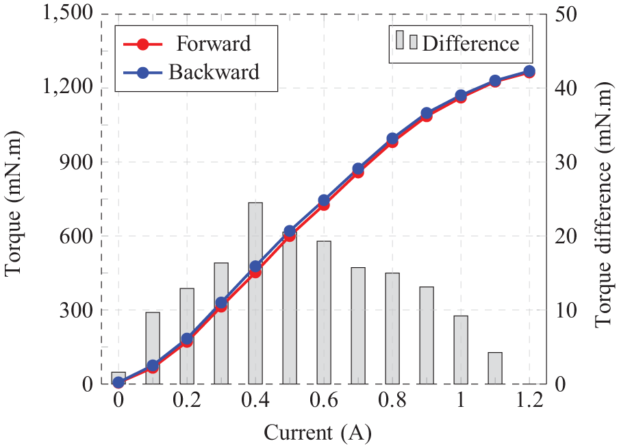
The objectives of this experiment were to find the actual current–torque relation of this brake and to evaluate the hysteresis impact on the torque output. At first, the drive motor rotated the brake at 15 r/min without current input. Then, the current was applied from 0 to 1.2 A in 0.1 A steps. After reaching 1.2 A, the current was released back to 0 A also in 0.1 A steps. The step holding time was 3 s for stable results. The average results of three experiments are displayed in Figure 9.
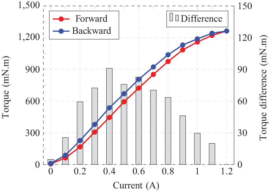
Current–torque relation of MR brake.
The initial off-state torque without current input was 6.21 mN m. Then, the forward torque showed a steady increase with current. At about 0.9 A, the torque saturation was observed, and this was consistent with the FEA result. The forward saturation torque was 1084.68 mN m, which was close to the 1084.33 mN m expected saturation torque. After 0.9 A, the torque showed slow growth with current until the brake reached the 1263.39 mN m maximum torque at 1.2 A. With releasing the current, the hysteresis impact on torque output appeared, which exhibited as the backward torque was larger than the forward torque under the same current input. The backward saturation torque was 1130.91 mN m, which was 46.23 mN m larger than the forward saturation torque. The maximum torque difference happened at 0.4 A. Under this current, the forward and backward torques were 445.74 mN m and 536.82 mN m, respectively. The maximum torque difference was calculated as 91.08 mN m, accounting for 7.2% of the total torque range. The final off-state torque was 11.04 mN m when the current was completely removed, which was almost 2 times of the initial off-state torque. The torque–volume ratio of this brake was calculated to be 41.252 kN/m2, which is larger than 9.8879 kN/m2 of the single-disk brake (Nam et al., 2008), 26.212 kN/m2 of the multi-disk brake (Qin et al., 2017), and 30.294 kN/m2 of the T-shaped brake (Avraam et al., 2010), but is smaller than 54.893 kN/m2 of the drum brake (Senkal and Gurocak, 2010). The dynamic range of the brake was calculated to be 41.17 dB, which is larger than 21 dB of the T-shaped brake (Avraam et al., 2010) and 39 dB of the multi-disk brake (Qin et al., 2017), but is smaller than 43 dB of the drum brake (Senkal and Gurocak, 2010) and 61.75 dB of the single-disk brake (Nam et al., 2008).
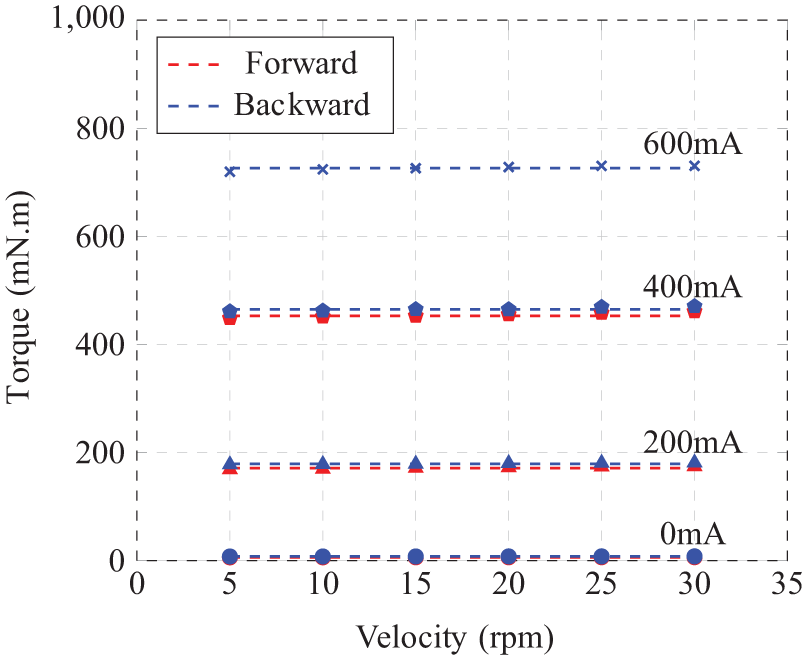
In order to provide wider observation of the braking torque characteristics, the brake was also evaluated under different velocities. In the experiment, the velocity was increased from 5 to 30 r/min with the step of 5 r/min. The current was increased from 0 to 0.6 A with the step of 0.2 A and then was released back to 0 A with the same step size. As shown in Figure 10, the velocities had very limited influence on the torque and hysteresis of the brake. Compared with the magnetic field, the influence of velocity on the torque characteristics can be neglected.
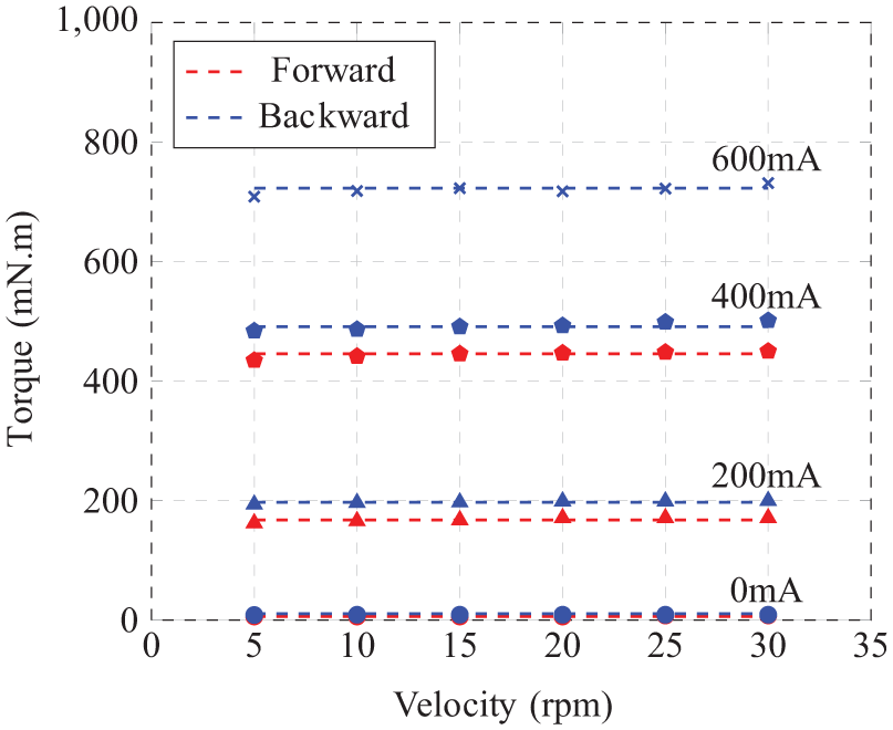
Influence of velocity on torque performance of MR brake.
2.4.2 Step response
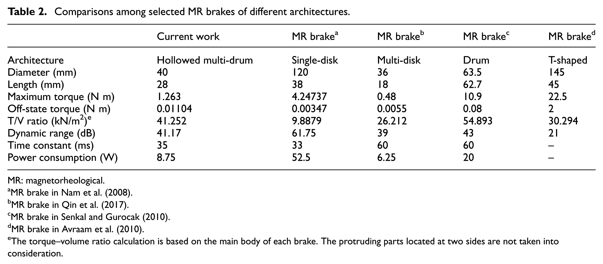
The objectives of this experiment were to determine the time constant of the brake and to evaluate the impact of different current levels on the brake response. The experiment was conducted under the current levels of 300, 500, 700, 900, and 1100 mA. The results of these five current levels are shown in Figure 11. The response of the brake under the step current is similar to that of a first-order system. Based on this, the time constant was measured to be about 35 ms, which is longer than 33 ms of the single-disk brake (Nam et al., 2008), but is shorter than 60 ms of the multi-disk brake (Qin et al., 2017) and the drum brake (Senkal and Gurocak, 2010). The current levels had no significant influence on the brake response. Parameters of this brake and its comparison with other brakes are listed in Table 2.
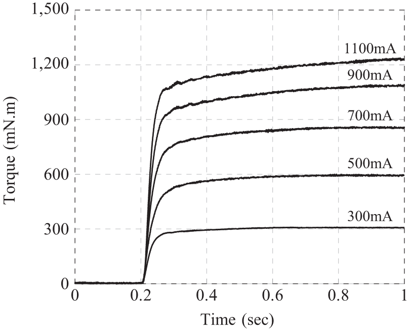
Step response of MR brake.
Comparisons among selected MR brakes of different architectures.
MR: magnetorheological.
MR brake in Nam et al. (2008).
MR brake in Qin et al. (2017).
MR brake in Senkal and Gurocak (2010).
MR brake in Avraam et al. (2010).
The torque–volume ratio calculation is based on the main body of each brake. The protruding parts located at two sides are not taken into consideration.
3. Hybrid actuator
3.1 Combination with DC micromotor
Considering the 91.08 mN m maximum torque difference, the micromotor (1524012SR, Faulhaber) was selected to construct a hybrid actuator (shown in Figure 12). Equipped with a gearbox and an encoder, the micromotor has the continuous torque of 100 mN m and the peak torque of 300 mN m with the angular resolution of 4096 PPR. The original micromotor cover is sightly modified. The micromotor is inserted into the micromotor cover. Its shaft is connected to the brake shaft by screws and its casing is fixed to the brake casing. The small sealed bearing (MR63ZZ, NSK) is used to support the micromotor shaft. The small magnetic ring is used to prevent the fluid from flowing into the micromotor.
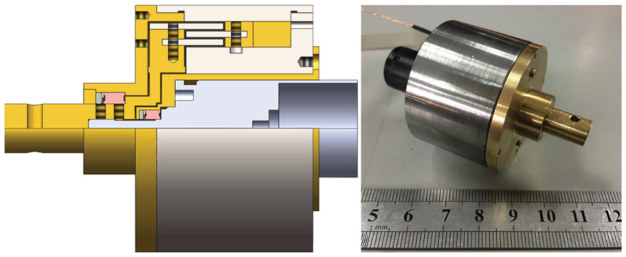
Hybrid actuator structure and prototype.
3.2 Actuator model and control scheme
The hybrid actuator model takes into account both the brake model and the micromotor model. The micromotor output

Therefore, the torque output of the hybrid actuator

It should be noted that the brake generates the torque that is opposite to the rotation direction. The micromotor torque depends on the error between the set torque and the actual torque.
A model was developed in controlling the hybrid actuator and its block diagram is displayed in Figure 13. The model was mainly implemented on the STM32 board. In the model, the hybrid actuator was driven by two servo controllers (ESCON 50/5, Maxon), which have the maximum current of 15 A and the maximum efficiency of 95%. The proportional–integral–derivative (PID) controller, which has the scan frequency of 53.6 kHz, was embedded in the servo controller. The brake was controlled to generate the set torque
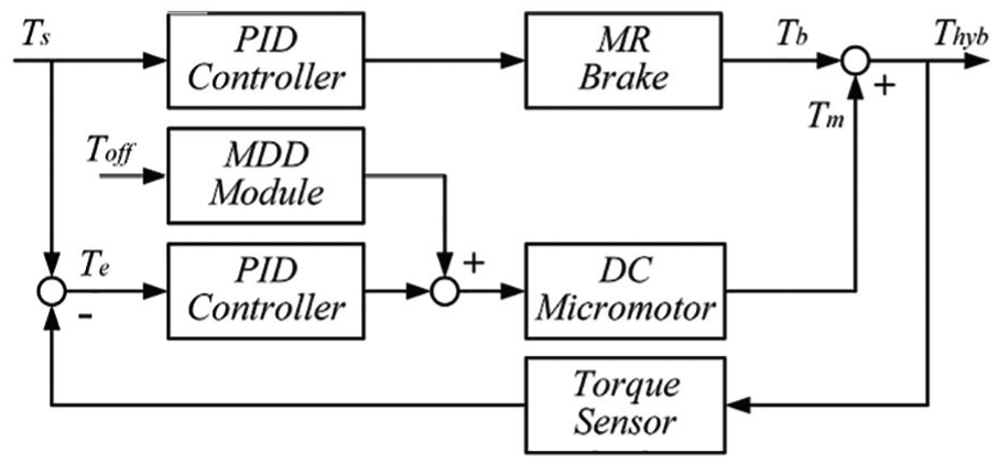
Control block diagram of hybrid actuator.
3.3 Actuator evaluation
Since the performance of the hybrid actuator without activating the micromotor was almost the same as that of the MR brake, the hybrid actuator was tested with activating both the MR brake and the micromotor in the following experiments.
3.3.1 Torque versus current
The current–torque experiments of the hybrid actuator under the constant and various velocities had the same procedures with those of the brake. In the experiments, the set torque was selected as the forward torque of the brake. The maximum error between
Current–torque relation of hybrid actuator.
Influence of velocity on torque performance of hybrid actuator.
Property comparison between hybrid actuator and MR brake.
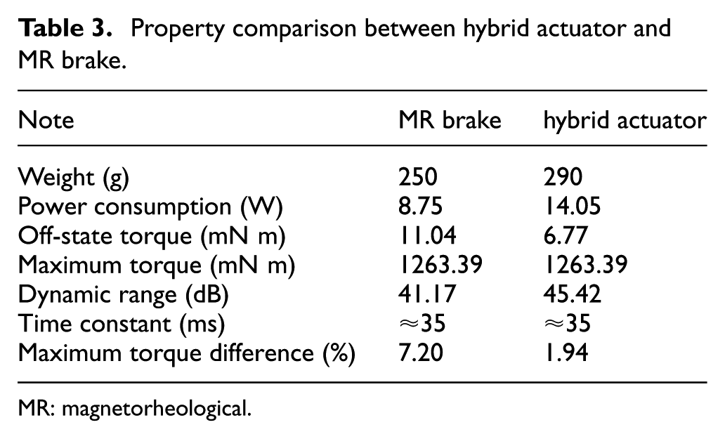
MR: magnetorheological.
3.3.2 Tracking of reference signals
The objective of this experiment was to evaluate the tracking performance of the brake and hybrid actuator to the reference signals. The sinusoidal and amplitude attenuation sinusoidal signals were selected. The experiment was conducted with activating the brake and the hybrid actuator, respectively. In this experiment, the set torque was still selected as the forward torque of the brake, and the maximum error between
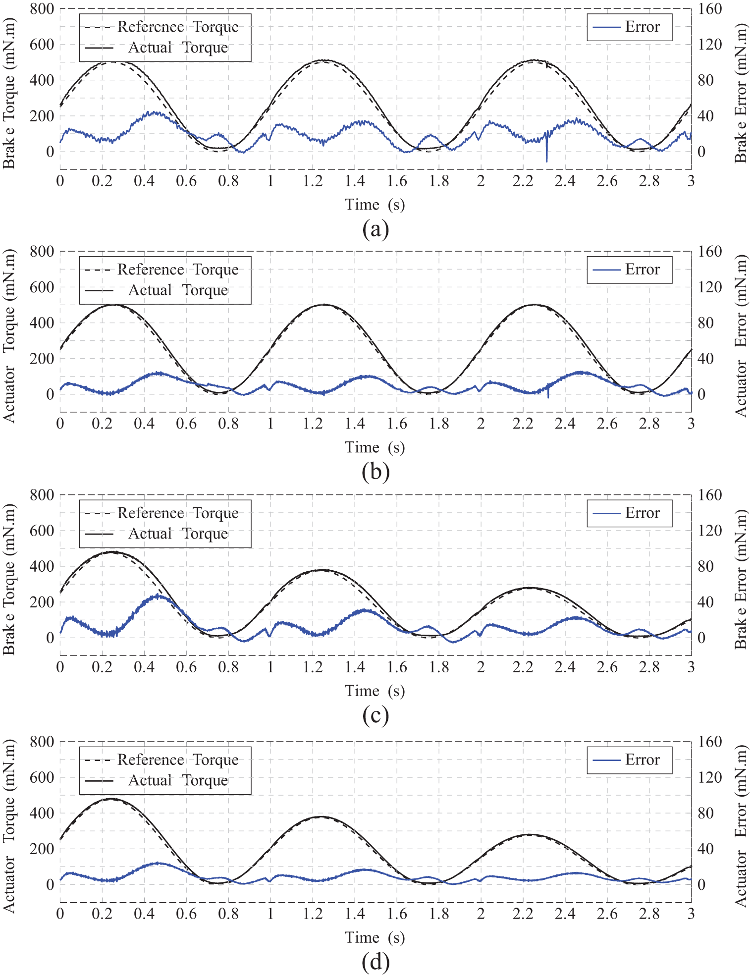
Tracking performance of reference signals: (a) brake to 1 Hz sinusoidal reference signal, (b) hybrid actuator to 1 Hz sinusoidal reference signal, (c) brake to amplitude attenuation sinusoidal reference signal, and (d) hybrid actuator to amplitude attenuation sinusoidal reference signal.
4. Conclusion
To deal with the magnetic hysteresis, an MR brake was combined with a micromotor to construct a hybrid actuator in this article. The novel hollowed multi-drum architecture was adopted for the brake so that the micromotor could be placed inside the brake to obtain a compact structure. The optimal brake has 40 mm diameter and 28 mm length. It could produce the maximum torque of 1263.39 mN m. Due to the magnetic hysteresis, the final off-state torque of the brake was 11.04 mN m, giving the dynamic range of 41.17 dB. Furthermore, the maximum difference between the forward and backward torque of the brake was 91.08 mN m, accounting for 7.20% of the total torque range. Through the closed-loop control, no obvious hysteresis loop was observed in the current–torque figure of the hybrid actuator. The maximum difference between the forward and backward torque was reduced to 24.52 mN m, accounting for only 1.94% of the total torque range. The final off-state torque was reduced to 6.77 mN m, increasing the dynamic range to 45.42 dB. The tracking experiment indicated that the hybrid actuator could track the reference signals more accurately than the brake. The RMSE for the 1 Hz sinusoidal signal of the hybrid actuator was 11.4852 mN m, smaller than 20.9570 mN m of the brake. The RMSE for the amplitude attenuation sinusoidal signal of the hybrid actuator was 9.3178 mN m, smaller than 15.5504 mN m of the brake. One limitation of this hybrid actuator is that an external force/torque sensor is required to provide the feedback signal. Future work will focus on equipping the hybrid actuator into a haptic device and evaluating its performance in actual haptic applications.
Footnotes
Declaration of conflicting interests
The author(s) declared no potential conflicts of interest with respect to the research, authorship, and/or publication of this article.
Funding
The author(s) disclosed receipt of the following financial support for the research, authorship, and/or publication of this article: This paper is supported by the National Key Research and Development Program of China under grant number 2016YFB1001301, the Natural Science Foundation of China under grant numbers 61325018 and 91648206, and the Scientific Research Foundation of Graduate School of Southeast University under grant number YBJJ1793.