
Abstract
Soil-liquefaction-induced damage has been a major cause of ground failure and led to structural damage in the past earthquake events. With recent shifts in civil engineering to performance-based design methods, the traditional factor-of-safety-based approach to avoid liquefaction initiation may not be economical to control liquefaction-induced deformations directly leading to damage. In this article, a novel approach using the magnetorheological effect of micron-sized magnetite particles in liquefied sand for post-liquefaction stabilization and deformation mitigation is proposed. The mixture of sand and micron-sized magnetite particles, termed as magnetorheological sand, illustrates field-dependent behavior similar to other magnetorheological materials. The magnetorheological effect is illustrated through a sinking cylinder test of saturated magnetorheological sand prepared with 90% F75 silica sand and 10% 30-micron magnetite particles by weight. The magnetic-field-dependent properties of magnetorheological sand are then fit to a numerical model for evaluation as a foundation material. The performance of a five-story structure resting on a layer of soil on rigid rock with soil–structure interaction is evaluated. The numerical simulation results demonstrate that magnetorheological sand is effective in mitigating liquefaction-induced deformation and has the potential to outperform alternative mitigation approaches.
1. Introduction
Soil liquefaction has been observed in many historical earthquake events, leading to ground failure and a major source of damage to structures and foundations (Akai et al., 1997; Ishihara and Koga, 1981; Seed, 1990; Shengcong and Tatsuoka, 1984; Yuan et al., 2004). Soil liquefaction is mostly caused by earthquake excitations that produce a sudden change of soil stress condition. It primarily develops in groundwater-saturated and loosely packed cohesionless coarse silt to fine sand at shallow depths. Liquefaction is characterized by the loss of soil shear strength due to the build-up of pore water pressure exceeding soil shear strength under dynamic loading. For structures, the loss of soil shear strength under seismic excitation means the loss of bearing capacity of the foundation, which results in large deformation of the ground. Large deformation of liquefied soil can be detrimental to civil structures, leading to unoccupiable structures or even collapse through induced instabilities. Soil liquefaction was found in 62% of 50 destructive earthquakes worldwide and induced 15%–30% of the earthquake damage (Bird and Bommer, 2004). Therefore, liquefaction mitigation has been studied over decades and still of great importance.
Liquefaction mitigation methods widely used in engineering practice include soil replacement, sand compaction piles, vibration compaction, blast compaction, grouting, deep mixing method, gravel pile method, dissipation using screen pipes, and lowering of the groundwater table. These traditional methods can be categorized into three main types: soil reinforcement, saturation degree reduction, and drainage (Hamada, 2014; Huang and Wen, 2015). Common among traditional methods, the goal is to prevent the initiation of liquefaction based on assessing the liquefaction potential with a factor of safety, which is the ratio between cyclic stress ratio (CSR) and cyclic resistance ratio (CRR) (Seed and Idriss, 1971). CSR is a measurement of the shear demand on the soil produced by the earthquake excitation, which can be determined based on depth, peak ground acceleration, and soil properties. CRR is a measurement of the shear strength of the soil and can be obtained either from laboratory tests simulating earthquake loading or from field tests such as the standard penetration test (SPT), the cone penetration test, the Becker penetration test, and the measurement of shear wave velocity. Therefore, to reduce liquefaction potential based on factor of safety, the key is to increase the effective stress through either improved soil properties or reduced pore water pressure. However, the factor of safety approach may not be adequate in preventing liquefaction initiation when an earthquake stronger than design level occurs or the site condition changes over time (i.e. the pore water pressure may increase due to the change in water table or overburden pressure from newly constructed structures). In other words, the structure will be left with inadequate protection if the liquefaction actually occurs. In addition, many traditional methods can only be applied in the construction process rather than in retrofit applications or to meet changing demands. Moving beyond the traditional liquefaction countermeasures aiming at reducing the probability to trigger liquefaction, further advances are needed in soil liquefaction mitigation to achieve performance-based design (Seed et al., 2003). Performance-based design approaches focus on achieving target levels of performance for given levels of hazard. In the context of liquefaction, the performance target may include the mitigation of structural or site displacements instead of reducing the risk of triggering liquefaction.
With the ongoing shift in practice toward performance-based design, attention is shifting to post-liquefaction strength, stability, and deformation. Possible models for the behavior of liquefied soil can be as a real liquid, a solid body with largely reduced shear stiffness, or a combined state of fluid and solid characteristics (Hamada et al., 1994). All of these models include a decrease in the shear modulus and shear strength, and the real liquid model includes a complete loss of shear modulus. The post-liquefaction soil behavior and its change of shear modulus have been studied in both laboratory tests and field test data. Yasuda et al. (1992) conducted a series of shaking table tests, vane shear tests, and cyclic torsional shear tests for sand specimens. They found that with increase in the shear strain, the fully liquefied soil specimen has a shear modulus that first decreases to about 0.1% of the original shear modulus and then increases when shear strain reaches a large value (about 10%) due to dilatancy. They further studied the influence of fines content, and described the reduction and subsequent increase in the shear modulus with an approximate bilinear model, together with a chart for parameter estimation based on fines content (Yasuda et al., 1998). Similar behavior was observed in the field records. For example, a maximum decrease of 80%–90% of original shear modulus due to liquefaction was estimated for the upper reclaimed-fill layer (0–18 m) at Port Island from the 1995 Kobe records, and similar recovery of shear modulus, as the experiment results in the literature, was shown, which began 3–5 min after the decrease in the intensity of strong ground motion (Pavlenko and Irikura, 2002). The laboratory test and field observation overall agree with each other, and a smaller liquefaction-induced reduction in shear modulus from field observation may be due to incomplete liquefaction of the soil. In accordance with the above-mentioned literature, the liquefied soil is assumed to exhibit a combination of fluid and solid characteristics with significantly reduced shear modulus in this research.
The goal of this research is to mitigate liquefaction-induced deformation and achieve stabilized site and safe structure performance. Considering the fluid-like behavior of liquefied soil, magnetically polarizable particles suspended in the liquefied soil present an exciting new approach for liquefaction damage mitigation. Magnetic particles suspended in a non-magnetic medium can form magnetorheological (MR) materials. These composite materials have rheological properties upon the application of a magnetic field. They are considered as a type of smart material for its variable properties in response to the change in magnetic field strength. The MR medium varies from fluid to foam to elastic solids; of which, the most common is MR fluid for use in MR dampers (Carlson and Jolly, 2000). In response to the external magnetic field, MR fluid is able to change the yield strength and other viscous characteristics of the composite due to the interaction between the magnetic particles under applied field. Similarly, MR elastomer is also field responsive, but typically characterized by a field-dependent modulus instead of yield strength. As an analog to the available media of MR materials, liquefied soil with combined fluid and solid characteristics is considered by the authors as a possible medium to carry magnetic particles and form a composite with a field-dependent modulus and yield strength for the use of post-liquefaction stabilization.
In this article, a new approach to mitigate the liquefaction-induced deformation for saturated sand using MR mechanism of micron-sized magnetite particles is proposed. The concept and principles of the MR mechanism of the sand and magnetite particle mixtures, named MR sand, are presented. Falling body tests, modified to evaluate liquefied soil and referred to herein as sinking body tests, are conducted to demonstrate the magnetic-field-dependent properties of the MR sand. In addition, simulations including soil–structure interaction (SSI) are performed under a set of earthquake excitations. Based on a comparison of the system response between the case with the proposed MR sand as the foundation soil and the case with foundation soil satisfying the traditional factor-of-safety-based requirement, the preliminary conclusion can be drawn that the MR sand can effectively mitigate liquefaction-induced deformation even when liquefaction is initiated. The reduction of deformation after liquefaction provides protection beyond factor of safety methods, applicable in performance-based design.
2. The MR sand
Inspired by the nature of liquefied soil with its combined characteristics of fluid and solid and its similarity with the non-magnetic carrier media of MR composites, a novel approach incorporating magnetically polarizable particles in liquefiable sandy soil to control the liquefaction-induced deformation is proposed and termed as MR sand in this article. The composition, MR effect mechanism, and field feasibility of the proposed MR sand are discussed in this section.
2.1. Composition and mechanism
The MR sand is intended to function under a saturated condition for sandy soil, which has a high potential of liquefaction occurrence. Therefore, its basic composition investigated in this article consists of sand particles, polarizable particles, and water. Different from the commonly used iron particles in most MR composites, magnetite (Fe3O4) particles are selected as the polarizable particles for MR sand considering the corrosive environment of soil. The size of magnetite particles can be determined based on the grain distribution of liquefiable sand of interest, especially needs to be smaller than the size of the majority of the fine grains in the sand to ensure the movement of the magnetite particles in forming chain-like structures under applied field. The determination of acceptable magnetite particle sized for MR sand will be discussed in the following section.
Figure 1 shows a schematic representation of the basic mechanism of the MR effect of the MR sand saturated in water. In Figure 1, the left image shows the solid state of the MR sand, while the right image shows the fluid-like state when liquefaction is initiated under earthquake excitations. In the solid state, the magnetite particles are not free to move under applied magnetic field due to the friction between sand particles under the compact grain structure. However, when the pore water pressure builds up under seismic excitations, the sand particles are gradually driven apart and liquefaction is triggered with a significant reduction in shear strength. In the liquefied state, the magnetite particles, polarized by the applied field, are able to move and form columnar structures parallel to the field through the interaction between the induced dipoles. As a result, these chain-like structures restrict the shear deformation of the liquefied sand, providing an increase in the shear stiffness, strength, and viscous characteristics. In addition, the mechanical energy needed to yield these columnar structures can be increased with stronger applied magnetic field, generating field-dependent properties including the yield stress under seismic shear. Thus, the liquefaction-induced shear deformation can be mitigated through the MR effect of the MR sand.
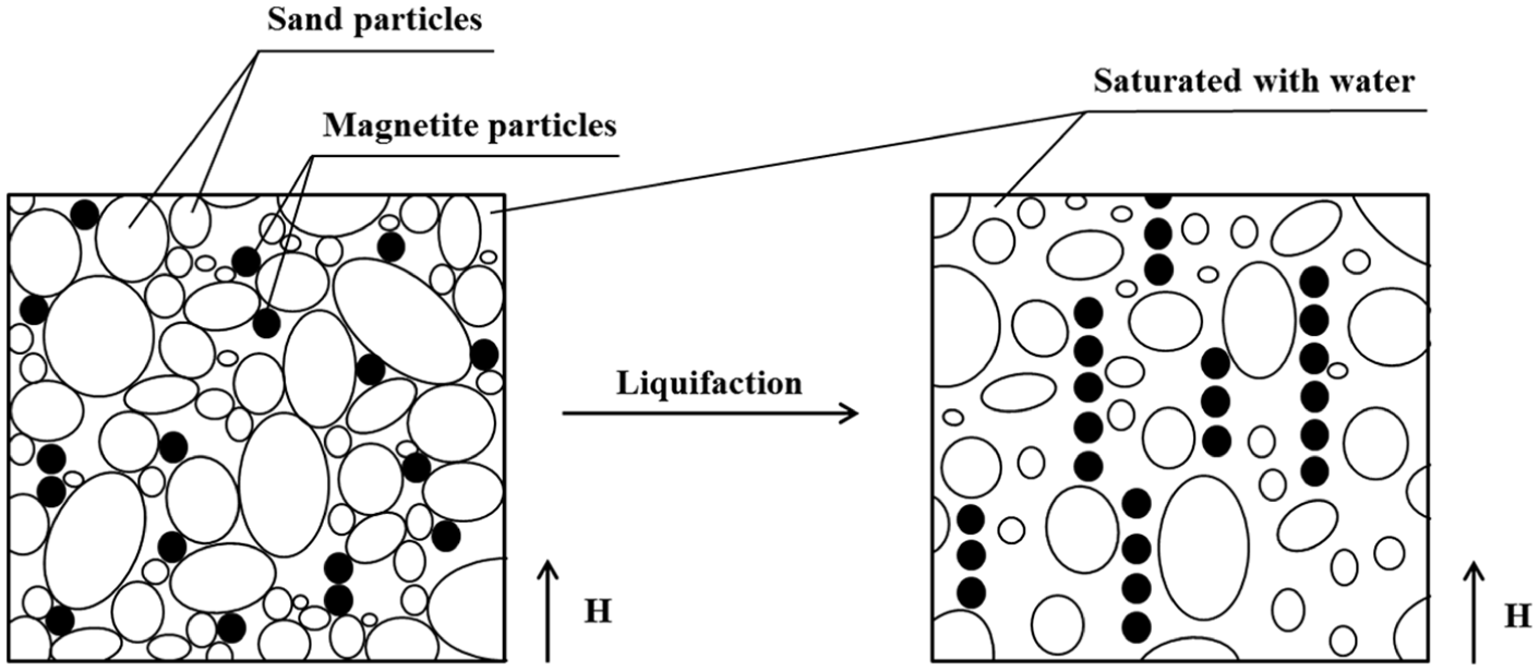
MR effect of the saturated MR sand under applied field H when liquefaction occurs.
2.2. Feasibility as a soil treatment
One of the challenges to utilize the MR effect of MR sand for the application of mitigation of liquefaction-induced deformation is the feasibility to mix the magnetite particles into the liquefiable sandy ground. One option is similar to the conventional permeation grouting process, where grout is injected into the soil matrix slowly with relatively low pressure so that the hydrofracturing of the soil can be avoided. This method is effective for sandy soil with less than 20% fines, which is the case for most the liquefiable cohesionless soil (higher fines content reduces the liquefaction potential). This permeation approach is also suitable for the treatment of soils close to sensitive existing structures and relatively easy for the treatment of a large area of liquefiable soil. To ensure the permeation of the grout particles into the soil matrix, the penetrability of the soil is the most important property, which highly depends on the grain size distribution of the soil and the grout. Applied to MR sand, this becomes the grain size distribution of the soil and magnetite. One of the criteria for assessing the penetrability is the groutability N, given in equation (1) (Incecik and Ceran, 1995)
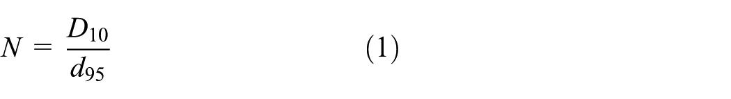
where D10 is the diameter through which 10% of the total soil mass passes (here, the sand) and d95 is diameter through which 95% of the total grout mass passes (here, the magnetite). According to equation (1), if N is larger than 11 (N > 11), grouting is possible; if N is smaller than 5 (N < 5), the grouting is not possible.
The groutability criteria can be used as a rough estimate to determine the size of the magnetite particle for the MR sand composite ensuring the feasibility for soil treatment in field. For the grain size range of liquefiable sandy soil, micron-sized magnetite particles are considered as an acceptable size.
2.3. Feasibility of large-scale magnetic field generation
Another challenge for the field application of the MR sand to mitigate liquefaction-induced deformation is the generation of magnetic field in large scale. For the proof-of-concept small-scale experimental study in this article, the magnetic field is generated by a pair of neodymium magnets with remanence of approximately 1.3T (detailed in section 3.1). A modest battery-powered electromagnet with the same magnetic strength is achievable using solenoid and metallic core with proper permeability. Depending on the specific geometric design required by the site condition (i.e. the thickness/depth of the liquefiable soil layer and the affected area), thicker wires can be considered to reduce the resistance of the solenoid and lower the needs on power supply. However, the actual magnetic field strength within the MR sand depends on the permeability of the sand composite and decays with increase in the distance from the source. To address this challenge, a grid pattern with multiple field generation sources can be considered to achieve large-area coverage of the magnetic field. Grid patterns are also commonly used in conventional liquefaction mitigation methods, such as grouting measures (Boulanger and Hayden, 1995; Mitchell, 2008). In addition, a larger fraction of magnetite particles or other magnetic particles with higher permeability can be considered to increase the field strength at distances further from the source. The feasibility of large-scale field generation requires additional large-scale experimental studies.
When considering existing structures, many conventional liquefaction mitigation approaches require structural retrofit to the foundation or soil replacement. An advantage of MR sand is that it can provide liquefaction mitigation for existing structures by treating the vulnerable soil around the structure. Both the treatment of soil and magnetic field generation installation can be completed after the foundation and structure are built.
3. Material behavior of the MR sand
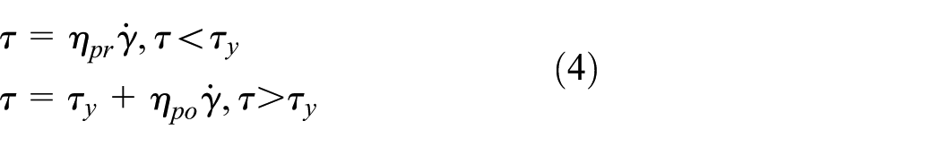
MR sand in a liquefied state is assumed to behave as heavy viscous fluid, a model suggested in literature for liquefied soil (Sawicki and Mierczyński, 2009; Sumer and Fredsøe, 2002). According to the often-used Bingham plastic model for the magnetic-field-dependent behavior of MR fluids, the fluid behaves as a viscoelastic solid until the variable field-dependent yield stress

where

where
In the proposed model, before liquefaction, the MR sand is assumed to follow equation (2) with a complex material modulus inherited from the nature of soil. After liquefaction, a biviscous model (Chopra and Sirohi, 2013) with pre-yield and post-yield viscosities
3.1. Material test methodology and setup
To model the behavior of liquefied MR sand under an applied field, the viscosity and yield stress must be measured. According to the Bingham plastic model, under fixed field strength, the relationship between the change of shear strain rate and the change of shear stress is linear, giving a Newtonian-like behavior under fixed shear stress and therefore constant shearing rate. In other words, the viscosity under constant field strength is a constant and can be measured directly from stress–strain rate relationship. Therefore, a constant magnetic field condition (on/off condition of field) is considered in this article. A falling body viscometer test (Leblanc, 1999) is adopted to demonstrate the field-dependent behavior of liquefied MR sand and measure the yield stress and viscosity. The setup is modified to create a controllable apparent density of the falling body as well as induce liquefaction in the soil during the test. Based on the expected viscosity of liquefied soil (Sumer and Fredsøe, 2002), a cylindrical mass is selected for the falling body method due to its larger measurable range of viscosity value (
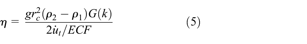
where g is the acceleration due to gravity,
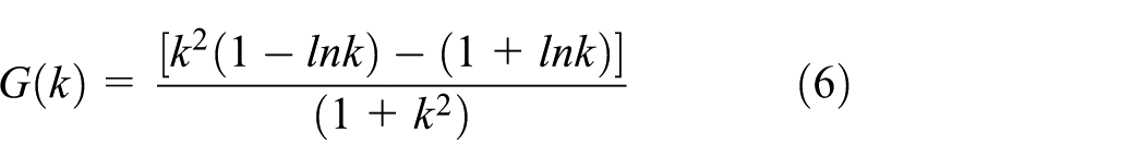
Schematic diagram of the falling cylinder viscometer.
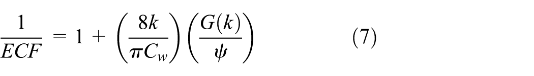
Using the falling cylinder method, the viscosity can be measured. However, the yield stress cannot be explicitly determined by measuring the terminal velocity of the falling cylinder. A relationship between the shear strain rate and shear stress of the liquefied MR sand is necessary, which requires the record of multiple shear stresses and corresponding terminal velocities. Therefore, a new sinking cylinder test, modified from the original falling cylinder viscometer test, is developed. Figure 3(a) shows a schematic configuration of the proposed setup for the new sinking cylinder test and Figure 3(b) shows the setup in lab with a zoom-in view of the major part of the setup. The dimensions are 25.4 mm for cylinder length L, 25.4 mm for cylinder radius
Sinking cylinder test setup: (a) schematic plot and (b) photo of test setup.
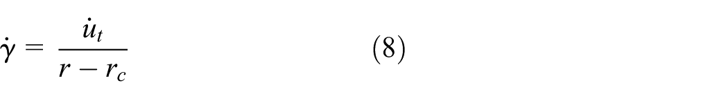
Note that the surface of the aluminum cylinder is smooth, so that the contribution of the force from liquefied MR sand mainly comes from viscous drag force in addition to buoyant force. This matches with the pre-yield behavior of the selected biviscous model. Weights can be added to the loading plate to provide different apparent forces due to gravity (appears as effective density of the cylinder and will be discussed later) in balance with the viscous drag force and buoyancy, generating different terminal velocities. The area in dashed lines marked 2 in Figure 3(a) represents the part of liquefied MR sand in simple shear mode, which is used for converting the set of terminal velocities and gravity forces into shear strain rates and shear stress using the viscosity η calculated from equations (8) and (9). With the multiple shear stresses and strain rates obtained from different applied gravity loads, and measured corresponding sinking displacements for Part 2 in simple shear mode, the stress and strain rate relation can be plotted and the yield stress can be obtained graphically.

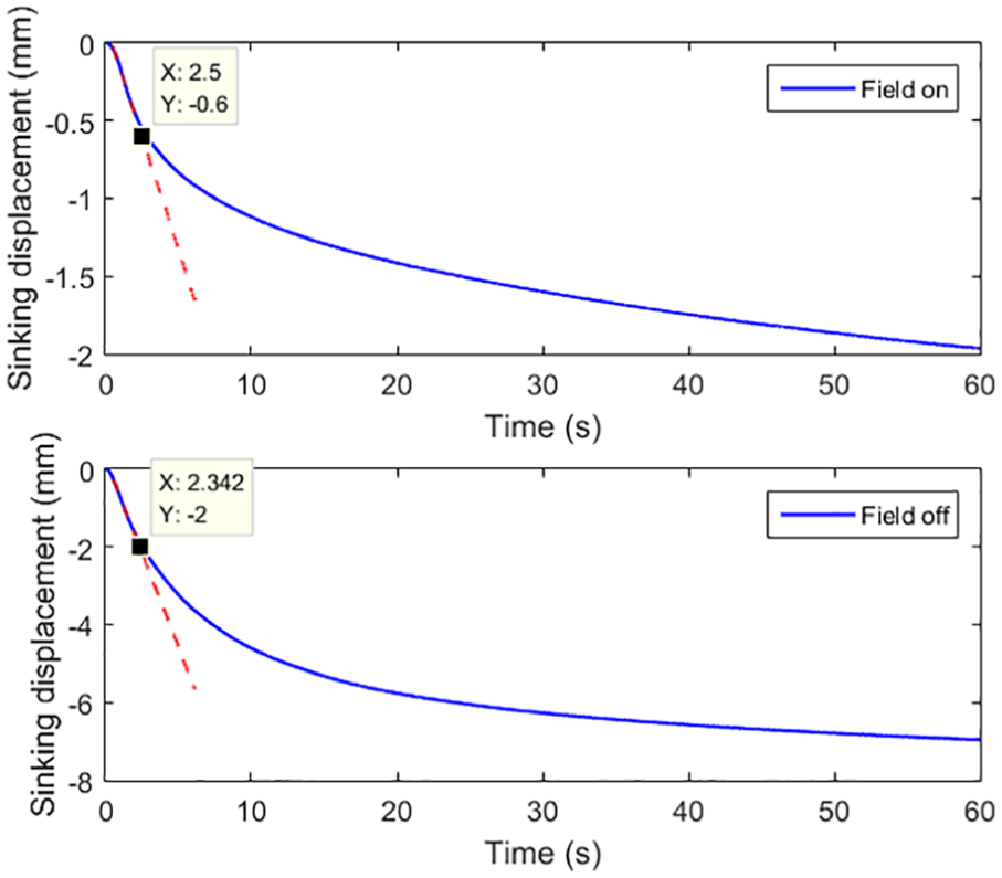
Another thing to note is that the MR sand may not be fully liquefied under the cyclic excitation from shake table, resulting in a gradual reduction of velocity over traveled vertical distance of the cylinder. A possible cause of this is the increase in the effective stress due to the rising overburden pressure toward lower depth. To account for this disturbance in the force balance, it is assumed that the part underneath the falling cylinder (Part 1 marked with dash line in Figure 3(a)) behaves as an elastic solid with weakened modulus due to partial liquefaction. The reduction in the modulus can be determined from the force balance at the turning point. The turning point is defined with the onset of reduction in falling velocity, which is located as the point of losing relatively linear slope in the measured sinking displacement curve over time. Namely, the turning point represents that the partial liquefied Part 2 starts to densify and returns to solid state. One set of the sinking displacement plots is given in Figure 4 as an example to illustrate the turning point (marked with a square point on the curve) and the terminal velocity. It can be seen from Figure 4 that the sinking displacement has an initial constant slope marked with dashed line, which indicates the terminal velocity
One set of sinking displacement measurements.
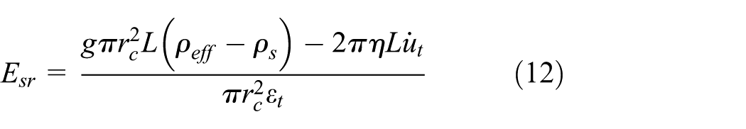
With the modification of test setup discussed above, equation (5) can be rewritten for the proposed sinking cylinder test as follows
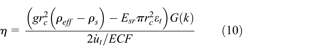
where
where
3.2. MR sand specimen
The sand used for the material test is F75 silica sand with grain size ranging from about 420–53 microns. Its grain distribution curve is plotted in Figure 5. The typical size of polarizable particles in MR composites is micron-sized (De Vicente et al., 2011) and is also the appropriate size for the magnetite particles in the MR sand specimen. In this preliminary test, the main purpose is to demonstrate and measure the MR effect of the MR sand, and the specimen is prepared through mixing instead of permeation. Therefore, the field groutability requirement is not considered in this laboratory test. A magnetite particle size of 30 microns is selected, smaller than the finest grain size of the F75 silica sand.
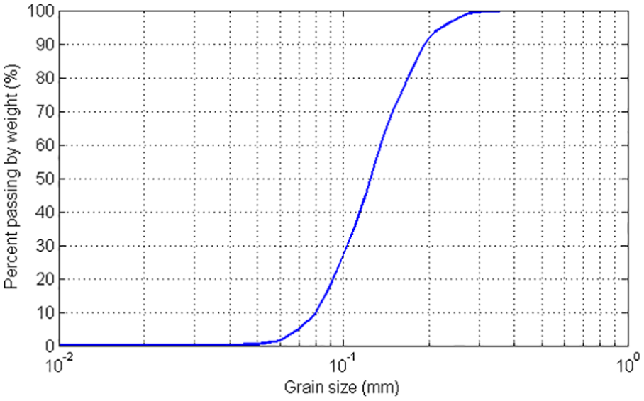
Grain size distribution of F75 silica sand used for preparing MR sand specimen.
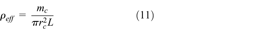
Considering the general range of magnetic particles volume percentage in MR fluid, the MR sand composite tested in this study consists of 10% of magnetite particles and 90% sand particles by weight. The dry specimen is prepared with hand mixing and filled into the cylinder container. Then, it is saturated with water above the surface for 5 mm to ensure saturation. The dry densities of the F75 silica sand and the MR sand mixture are measured based on ASTM standard (ASTM D4254, 2000). The minimum index density is 1.44 g/cm3 for the F75 silica sand and 1.52 g/cm3 for the MR sand; while the maximum index density is 1.63 g/cm3 for the F75 silica sand and 1.75 g/cm3 for the MR sand. The saturated density of the MR sand
3.3. Experimental measurement of MR sand properties
To obtain the relationship between shear stress and strain rate of the MR sand body in simple shear mode (Part 2 of Figure 3(a)), 14 different weights are applied to the sinking cylinder test, resulting in 14 sets of sinking displacement measurements used to calculate viscosity, stress, and strain rates based on equations (6) to (11). Tests are conducted for both field-on and field-off cases. The original value of elastic modulus of the MR soil (Part 1 in Figure 3(a)) is determined from the original shear modulus for the 14 different settings of applied pressure based on the maximum shear modulus prediction by Seed and Idriss (1970). Based on the material test methodology discussed in section 3.1, the ratio between the reduced elastic/shear modulus due to liquefaction and the original maximum elastic/shear modulus of the MR sand is determined as 3.2% by taking an average of the 14 sets of test. Note that it is larger than the 0.1% ratio reported in the literature from laboratory measurements (Yasuda et al., 1992), but below the values observed in field records (Pavlenko and Irikura, 2002), likely because the MR sand body is not fully liquefied, especially the part at lower depths (Part 1 in Figure 3(a)).
Figure 4 shows one set of the sinking displacement measurements, an important observation is the significantly reduced amount of sinking of the cylinder body in the case with magnetic field on. This demonstrates the ability of the MR sand to mitigate liquefaction-induced deformation under magnetic field. The calculated stress and strain rate data for all 28 sets are plotted in Figure 6 with a linear line fit to the field-off data set and a bilinear line fit to the field-on data set. Note that two outliers that are far from the other data are excluded for the field-off case. A possible cause for the two outliers is the larger overburden pressure under the largest two applied loads that decreases the level of liquefaction in the specimen, especially for Part 2 (Figure 3(a)). Bilinear behavior of the field-on case is shown in the shear stress–strain rate relation, which agrees with the biviscous model of MR fluid. The point marked in Figure 6 at the change of slope refers to the yield point of the liquefied MR sand specimen under applied magnetic field. In the field-on case, the pre-yield viscosity/slope
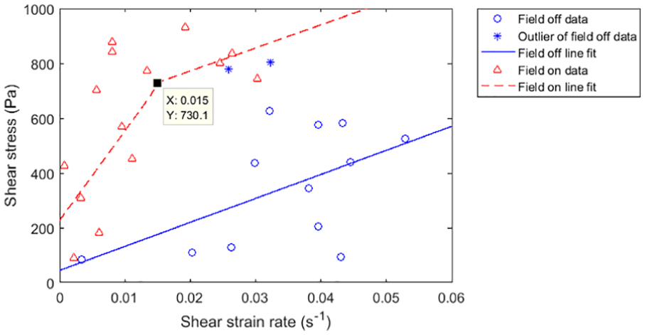
Shear stress–strain rate relation obtained from sinking cylinder tests.
4. Performance of the MR sand on mitigation of liquefaction-induced deformation
With the MR effect of the MR sand confirmed in the small-scale sinking cylinder test, numerical simulations implementing the MR sand as foundation soil with SSI effect included are conducted to investigate its performance as a potential approach for the mitigation of liquefaction-induced deformation. The response of a structure under a set of four ground motion excitations is made between cases with foundation soil selected as MR sand (70% relative density) with field off and on, and the original F75 sand that satisfies the factor of safety requirement with relative density of 50% considered as an untreated case and a case treated to the same 70% relative density as MR sand.
4.1. Model of the SSI system
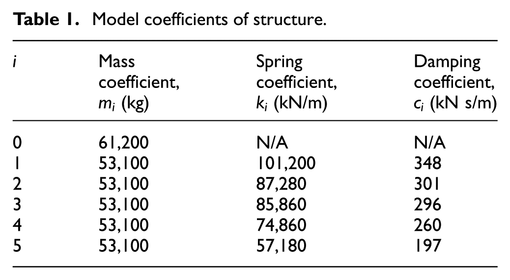
A 5-degree-of-freedom (DOF) structure (Kelly et al., 1987) resting on a layer of saturated soil on rigid rock is considered for the SSI simulation as shown in Figure 7. The model parameters are given in Table 1 (the original structure is a base isolation structure, therefore the current model is assumed to be without isolation, the other properties are scaled to full scale based on (Kelly et al., 1987)). Six horizontal DOFs and one rocking DOF at base are considered for the structure by treating the structure as a rigid block in the rocking DOF. The layer of soil on rigid rock is assigned with properties of saturated MR sand scaled up from small-scale sinking cylinder test results or the properties of F75 sand (50% and 70% relative density) for comparison. The coupling of rocking and horizontal DOFs is considered for the foundation soil layer in the SSI system. Both radiation damping and material damping are taken into consideration for the soil layer. The equivalent foundation disk radius
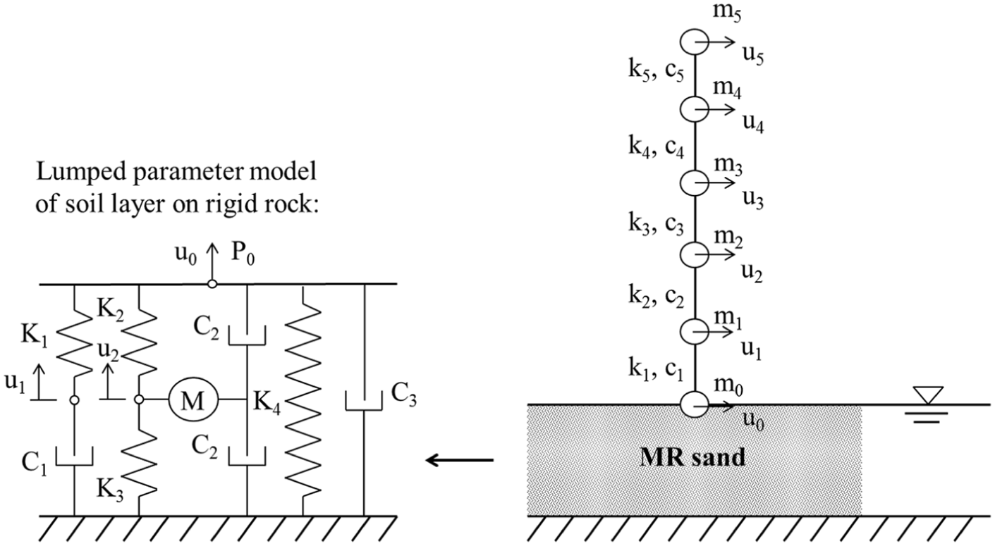
SSI system for simulation.
Model coefficients of structure.
The equations of motion for the SSI system are formed in frequency domain with a frequency-dependent dynamic stiffness and coupled horizontal and rocking DOF (Wolf, 1994)
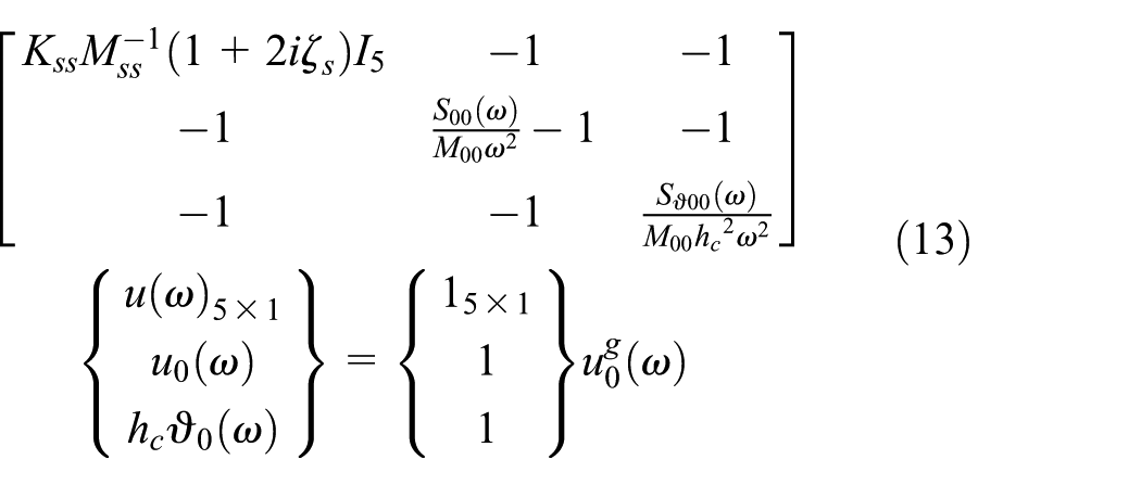
where
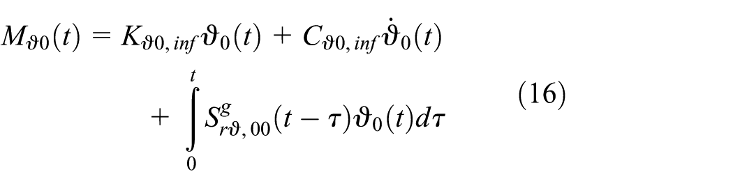
The time-domain formulation of equation (13) is as follows
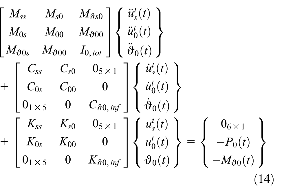
where, in addition to the parameters introduced for the frequency domain formulation,
In time domain, for the horizontal DOFs of the superstructure stories and the base and the rocking DOF of the base:
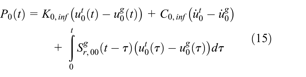
where


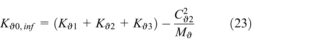
With the dynamic stiffness of horizontal and rocking DOFs derived based on the LPM in Figure 7 (note that the first term with
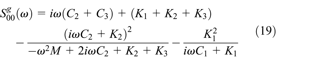
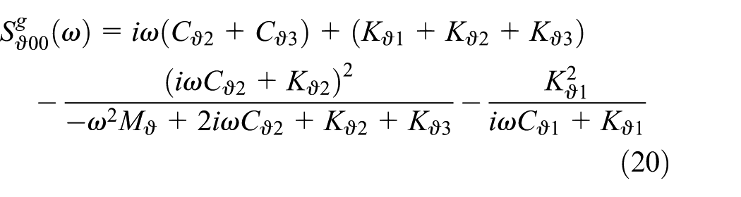
Therefore, the high frequency limits of the dynamic stiffness can be determined as
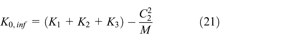


The spring and dashpot coefficients can be calculated as
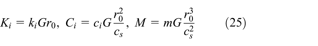
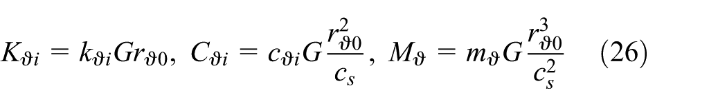
where the shear modulus G is taken as the strain dependent modulus and updated according to the current shear strain

where maximum shear modulus
Dimensionless coefficients of LPM.
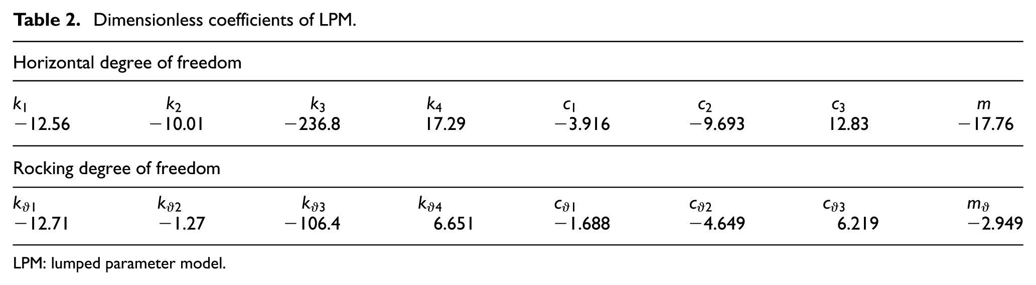
LPM: lumped parameter model.
With a material damping ratio
After liquefaction is initiated, the modulus G is updated accordingly. For the F75 sand, the shear modulus is reduced to 0.1% of the original G value (Yasuda et al., 1992). For the MR sand, the post-liquefaction modulus is determined from the damping scaled from the sinking cylinder test measurement (
For comparison with traditional soil reinforcement methods that mostly provide increased soil relative density and therefore increased effective stress to reduce liquefaction potential, the seismic response of the original F75 sand with 50% and 70% relative density as foundation soil layer are investigated together with that of the MR sand of 70% relative density with field-on and -off conditions. The F75 sand of 50% has a factor of safety of 1.39 for high seismic areas with maximum acceleration amplitude of 0.35g and earthquake magnitude of 7.5, which is larger than the minimum acceptable factor of safety of 1.25 and judged to be safe (Seed and Idriss, 1982). The evaluation of factor of safety is determined based on estimated SPT-N value from relative density, grain size distribution and effective overburden pressure (Cubrinovski and Ishihara, 1999), and the liquefaction potential evaluation procedure (Seed and Idriss, 1971). The F75 sand of 70% relative density is selected in comparison with the MR for its same relative density. The basic soil properties for determining SSI model settings of each foundation soil type are summarized in Table 3, in which the friction angles are estimated based on relative density (Meyerhof, 1956).
SSI foundation soil properties.
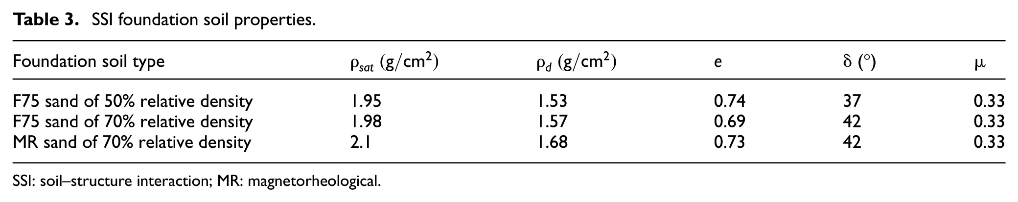
SSI: soil–structure interaction; MR: magnetorheological.
4.2. Simulation results
The frequency response for the effective base input
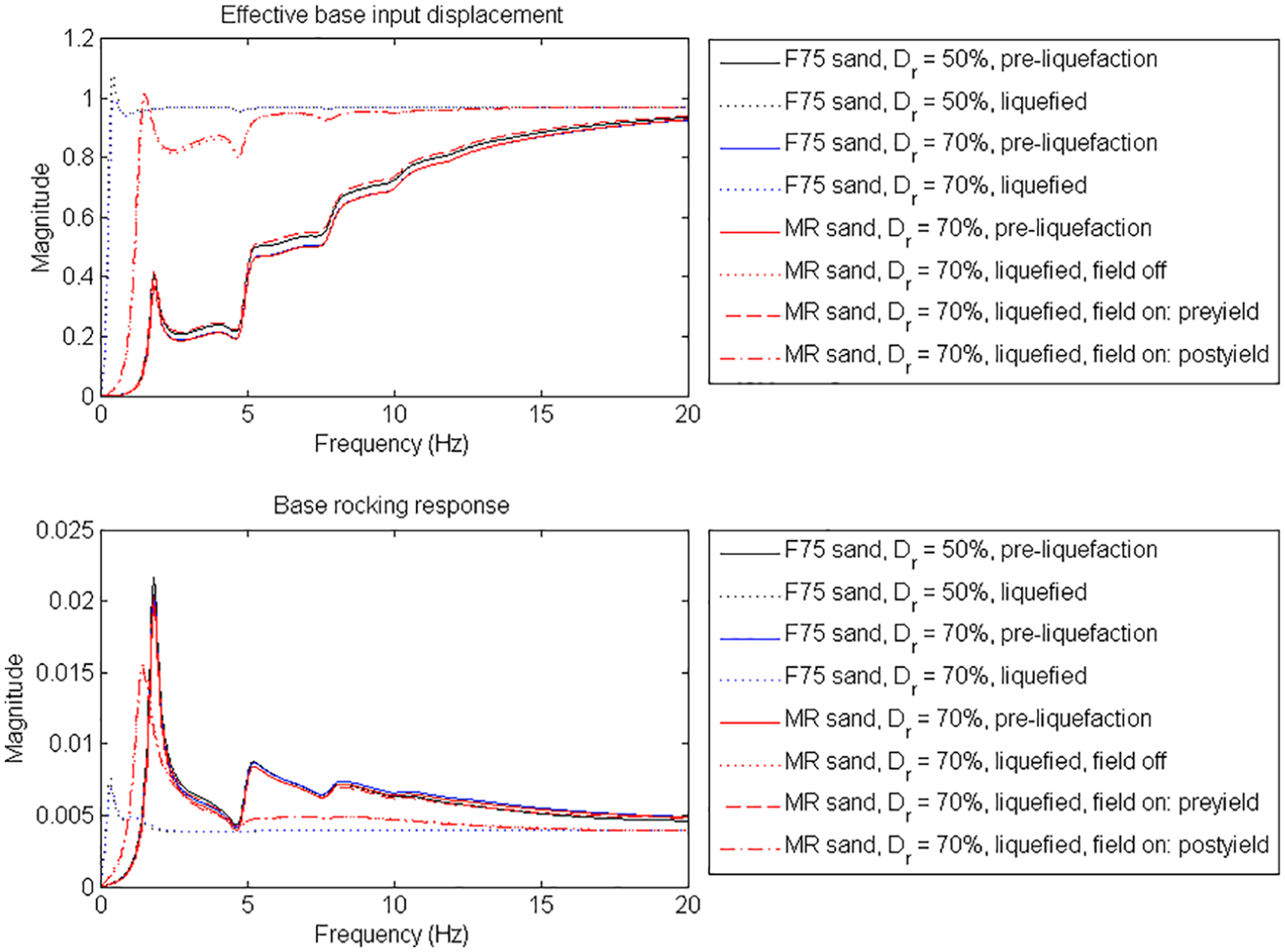
Frequency response of horizontal and rocking DOFs at base.
Furthermore, nonlinear time-domain analysis is performed under four sets of ground motion for the three types of foundation soil and with magnetic field-on/-off conditions. The four sets of earthquakes are El Centro (Mw 6.4, 1979), Hachinohe (Mw 7.5, 1968), Northridge (Mw 6.7, 1994), and Kobe (Mw 6.8, 1995). The results are summarized in Table 4. For the four sets of ground motion, liquefaction is only avoided under Hachinohe earthquake, which has the smallest maximum acceleration. Under Hachinohe with no liquefaction occurred, the response is the same for the MR sand with field-on/-off conditions since the MR effect only functions when liquefaction initiates; the response is quite similar between the MR sand and F75 sand with 50% or 70% relative density due to similar saturated density and therefore modulus value, slightly larger ground maximum deformations
Results of nonlinear time-domain analysis.
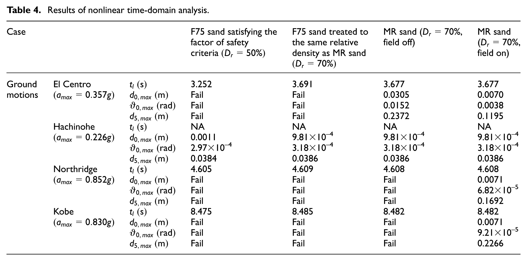
For the liquefied cases under El Centro, Northridge, and Kobe, a significant mitigation of deformations can be found for the MR sand with field-on condition compared to the F75 sand cases where the SSI system responses with an excessive deformation that indicates the failure under liquefaction. Figure 9 presents the set of results for all cases under Northridge earthquake for illustration. The horizontal displacement and base rocking response clearly indicate the ground or superstructure failure due to liquefaction of the cases except for the MR sand with field-on condition. Note that the F75 sand shows a lower stiffness in the post-liquefaction phase compared to the MR sand with field-off condition due to the assumption that shear modulus reduces to 0.1% of G, which is lower than that measured in the sinking cylinder test for the MR sand. Also, a reduction in liquefaction-induced deformation using the MR sand as foundation soil layer with applied magnetic field is demonstrated. The shear strain response confirms the initiation of liquefaction under the 0.2% triggering shear strain threshold. In addition, the shear stress response is still below the yield stress of 0.85 MPa of the MR sand as full-scale foundation soil layer under applied field. Although the yield stress may be reached under an even stronger seismic excitation, the yield stress can be increased as a field-dependent property under stronger magnetic field similar to other MR materials. The interaction force and moment at base also suggest the stabilization provided by the MR sand with field-on and the failure due to liquefaction of the other cases. Overall, the MR sand under applied magnetic field demonstrates an effective function on the mitigation of post-liquefaction deformation.
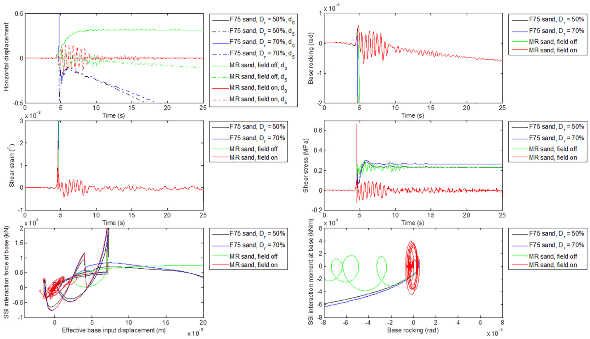
Liquefied SSI response under Northridge earthquake excitation.
5. Conclusion
A novel approach utilizing the MR effect of micron-sized magnetite particles in liquefied sand, termed MR sand, is proposed in this research for post-liquefaction stabilization and deformation mitigation. A small-scale sinking cylinder test is developed to demonstrate and measure the field-dependent viscosity and yield stress of the MR sand in liquefied state. As an initial study to understand the field-dependent properties of the liquefied MR sand, biviscous model is assumed and constant magnetic field is applied using neodymium magnets. MR sand specimen prepared with 90% F75 silica sand and 10% 30-micron magnetite particles by weight is investigated. The stress and strain rate relation and the yield stress are obtained graphically from the test measurement data. The experiment results illustrate a field-dependent behavior of the liquefied MR sand and confirmed the biviscous model assumption.
Furthermore, numerical simulations including SSI effect are performed to evaluate the performance of the MR sand as foundation soil to control the post-liquefaction deformation. The foundation soil under seismic excitation, the original F75 sand that satisfies the traditional factor of safety criterion (50% relative density), and F75 sand treated to the same relative density (70%) as the MR sand specimen are taken for comparison with the MR sand under field-on/-off conditions. Their SSI responses are compared under a set of four ground motions. The results demonstrate the capability of the MR sand under magnetic field to effectively mitigate the liquefaction-induced deformation and stabilize the structure in the post-liquefaction phase, which outperforms the cases with satisfactory factor of safety against liquefaction. With showing great potential for post-liquefaction stabilization and deformation mitigation, the challenge still remains for the generation of large-scale magnetic field, for which future study is needed.
Footnotes
Declaration of conflicting interests
The author(s) declared no potential conflicts of interest with respect to the research, authorship, and/or publication of this article.
Funding
The author(s) received no financial support for the research, authorship, and/or publication of this article.