
Abstract
This article presents a novel rotary shock absorber which combines the abilities of variable stiffness and variable damping by assembling a set of two magnetorheological damping units, one of which being placed in series with a rubber spring. This allows the damping and stiffness to be controlled independently by the internal damping and the external damping units, respectively. A test bench was established to verify the variable stiffness and damping functionality. The experimental results for variable damping test, variable stiffness test and co-working test are presented. At the amplitude of 10° and the frequency 0.5 Hz, increases of 141.6% and 618.1% are obtained for damping and stiffness separately if the corresponding current increased from 0 to 1 A and from 0 to 2 A, respectively. A mathematical model is then developed and verified to predict the changing of the damping and stiffness. The test results and the simulated model confirm the feasibility of the shock absorber with the ability of varying damping and stiffness simultaneously.
1. Introduction
Magnetorheological fluid (MRF) is a kind of smart material that possesses controllable rheological properties under the application of a magnetic flux. This change presents itself as an apparent increase in viscosity, occurring rapidly within a few milliseconds (Carlson and Jolly, 2000; Muhammad et al., 2006). Without a magnetic field applied, MRF is in free-flowing state, sometimes referred to as the ‘off-state’. In this state, the plastic viscosity of the material is controlled only by the viscosity of the carrying liquid and particle volume fractions. In contrast, MRFs will change to a semi-solid state (‘on-state’) when exposed to external magnetic field. In this state, MRFs exhibit field-dependent behaviour characterised by a variable yield stress, dependent on the applied magnetic field strength. After the yield stress is surpassed by an applied shear stress, MRFs revert back to the free-flow state with nearly unchanged plastic viscosity (Goncalves and Carlson, 2007; Zhu et al., 2012). Apart from the advantage of a fast response, MRF also has the characteristics of low operational power consumption since a magnetic field–induced yield stress of MRF can be achieved using an electromagnet with a low voltage and modest current (Olabi and Grunwald, 2007). Thus, since first introduced in 1984 (Rabinow, 1948), MRF attracted a lot of research attention in applications such as civil engineering (Christie et al., 2019; Dyke et al., 1996; Housner et al., 1997; Jung et al., 2004; Tse and Chang, 2004), medical rehabilitation and surgery (Carlson et al., 2001; Gudmundsson et al., 2010; Liu et al., 2006; Nguyen et al., 2011b), and automotive design (Neelakantan and Washington, 2005; Sassi et al., 2005; Sun et al., 2015, 2016, 2017; Tang et al., 2017).
Among all of the applications for MRFs, the most common mechanical design utilising the material is the magnetorheological damper, referred to as MR damper. Depending on whether the input to these dampers is linear or angular, they may be classed as either linear or rotary MR dampers. Linear MR dampers are commonly studied in the areas of vibration control. However, these linear dampers tend to require larger installation space than rotary dampers. In addition, the surface of the linear damper rod is usually exposed to the environment, making the damper more easily damaged by other objects (Els and Holman, 1999). Furthermore, the linear MR damper requires a relatively large amount of costly MRF which may increase cost to some extent (Giorgetti et al., 2010). Thus, the rotary MR dampers are considered as an advantageous alternative to linear versions in some cases and are developed for many purposes. In addition, the rotary damper is inherently suitable in all rotary movement–based applications, namely, braking devices and angular joints. As some examples of uses, rotary MR dampers can be used in the areas of position control and vibration attenuation. Sapiński et al. (2018) demonstrated the application of a rotary MR damper in position control. The dynamic behaviour of the designed system was improved using various control methods. Yang et al. (2012) used a compact and light-weight rotary MR damper in pathological tremor suppression.
In terms of the structure of rotary MR dampers, they are typically divided into drum-, disc- and hybrid-type rotary dampers, according to the location of the effective shear area (Imaduddin et al., 2013). In the case of drum-type dampers, Huang et al. (2002) theoretically investigated the design method of these dampers, the torque of which could be increased by expanding the effective area (Huang et al., 2002; Nam and Ahn, 2009) and optimising magnetic field strength (Kikuchi and Kobayashi, 2011; Senkal and Gurocak, 2009). As for disc-type MR dampers, Li and Du (2003) were among the first to present the development of such a device, using a single disc. Later, multi-disc MR dampers were researched (Ismail et al., 2012; Park et al., 2006) in order to improve performance and torque output by providing more shear surfaces. Combining these disc- and drum-type designs, a hybrid-type MR damper was later introduced (Nguyen and Choi, 2011; Nguyen et al., 2011a). While other more complex structures of rotary MR dampers do exist, those reported in literature typically serve only to provide variable damping, and this is what they have in common.
The use of rotary MR dampers to provide variable stiffness, rather than variable damping, is quite a new concept. Furthermore, simultaneously providing variable stiffness and damping using rotary MR dampers has not been reported. Variable stiffness and damping abilities are regarded as important features in some applications, especially in vibration control. Taking vibration control as an example, the quantity of vibration energy dissipated in a system could be controlled by adjusting the damping, such that the vibration magnitude would be reduced. In addition, vibration could also be suppressed by varying the system’s stiffness, as it can shift the resonant frequency of the system away from a given excitation frequency. Considering the importance of both the stiffness variability and the damping variability, a new rotary damper capable of controlling its damping and stiffness should be developed and investigated systematically.
Following the previous work [19] of the co-author, Sun, which focus on the development of a compact linear variable stiffness and damping MR damper, this article presents a rotary variable stiffness and damping shock absorber based on MR technology. The proposed rotary shock absorber consists of a rubber spring and two rotary MR damping cylinders, one of which acts in series with a spring. As the two dampers are connected in parallel, the damping and stiffness of the device can be controlled independently. The remainder of this article is organised as follows. The structural design, working principle and magnetic field simulation of the proposed shock absorber are introduced in Section 2. In Section 3, the experimental test rig for the characterisation of the manufactured shock absorber is presented. The experimental results are presented and analysed in Section 4. Following this, Section 5 focuses on the development of the mathematical model for the designed shock absorber. In addition, the numerical model parameters for the internal damper and the external damper were also identified in this section. Finally, Sections 6 and 7, respectively, present the discussion and conclusion.
2. Structure and analysis of the MRF rotary damper
2.1. Structure of the MRF rotary damper
As shown in Figure 1, the proposed shock absorber consists of a set of two damper structures: a drum-type internal damper and a disc-type external damper. The shaft is connected to the internal damper rotor and the plate. A motor can be mounted to the base to drive the proposed damper from the bottom, with the plate on the top serving as the output. A cylindrical rubber spring made of silicone rubber (M4601A/B, Barnes crop.) is mounted between the plate and the external damper casing. As the internal damper casing is connected to the unmovable (fixed) plate and the external damper disc, both the internal damper casing and the external damper disc keep still, while the internal damper rotor and the external damper casing may spin, following the shaft. Basically, all the parts in the yellow block are fixed and cannot rotate, while other parts are able to rotate following the shaft. MRF (MRF-122EG, Lord corp.) is filled in the two 0.8-mm-gap chambers of both internal and external dampers. The internal damper coil is seated in the internal damper rotor, while the external damper coil is mounted to the external damper casing. Both of these coils can generate magnetic flux to control the yield stress of the MRFs contained inside. Here, the internal damper current and the external damper current are assigned as I1 and I2, respectively. In order to optimise the magnetic flux path, the part connecting the internal and the external dampers was made of aluminium with a low magnetic permeability, while other parts are made of low carbon steel with a high magnetic permeability. In addition, alimimium was also used for both the internal damper lid and the casing to guide the magnetic flux to pass through MRF gap for the purpose of realising a high magnetic flux density across MRF working area. As shown in Figure 1, the captions of the rubber spring, the internal and the external damper coil, and the aluminium parts are in green, indicating non-ferromagnetic, while other parts with black caption are ferromagnetic.
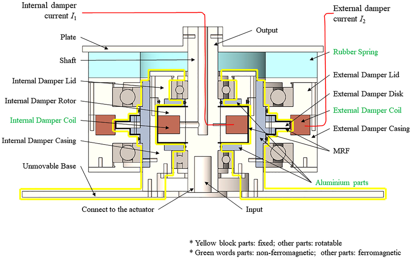
Structure of the variable stiffness and damping rotary MR shock absorber.
2.2. Working principle
If no current is applied to both the internal damper coil and the external damper coil, all the parts except the ones in yellow block in Figure 1: the internal damper rotor, the plate, the rubber spring, and the external damper casing can rotate freely with the shaft. The rubber spring will only experience a small strain due to the inertial torque of the external damper. By providing current I1 to the internal damper coil, variable damping is realised, with the relative movement between the internal damper rotor and the casing restrained by the semi-solid MRF between them. If even a small current I2 is given to the external damper coil, the external damper casing would not be able to freely rotate from the external damper disc due to the braking torque induced by the MRF. However, the plate is able to always move simultaneously with the shaft. As a result, the rubber spring would be stretched, which largely increases the stiffness of the entire device. As such, damping variability is achieved through the regulation of the internal damper current I1, while the external damper current I2 can control the stiffness of the device.
2.3. Magnetic field simulation
In order to provide guidance to the damper design, the induced magnetic field of the proposed damper was simulated using COMSOL Multiphysics with a two-dimensional (2D) axisymmetric study, with the results being shown in Figure 2(a). The internal damper coil has 500 turns with 0.5 mm diameter and 7.8 Ω resistance copper wire, while the external damper coil has 200 turns with 0.5 mm diameter and 10.9 Ω resistance copper wire. From Figure 2(a), it can be noted that the aluminium part connecting the external damper disc and the internal damper casing effectively builds a barrier between the internal magnetic circulation and the external magnetic circulation, so the magnetic field interference between the two damping units is minimised. For the same reason, additional aluminium parts were added to the internal damper to guide the magnetic flux where desired. Thus, the magnetic flux of each can be separately controlled by the internal current I1 and external current I2, without mutual interference.
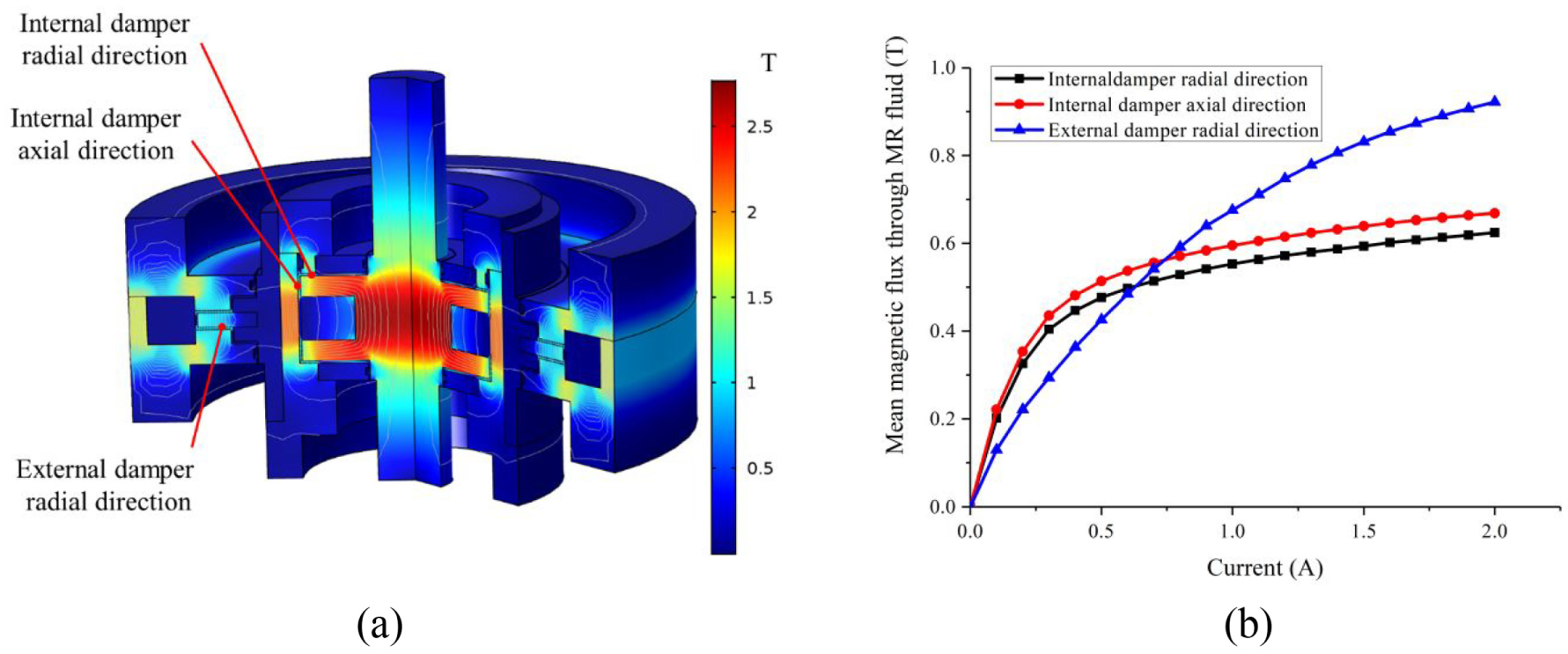
Magnetic field simulation: (a) modelled damper and (b) average flux through the MRF for varied currents.
For the internal damper, the working area of the MRF is on the upper and lower gaps (i.e. the surfaces in the radial direction) and the small gaps between the drum and the internal damper casing (in the axial direction). As for the external damper, the upper and lower gaps between the disc and the casing (in the radial direction) serve as the working area. Thus, the relationship between the mean magnetic flux in these working areas and the current is plotted in Figure 2(b). The magnetic flux of the MRF in both the internal damper and the external damper increases continuously with the increasing current. The maximum mean flux of the external damper was found to be 0.918 T at 2.0 A. Given this appears sufficient for the selected MRF, the current range of 0–2.0 A was set for the external damper coil. In contrast, the magnetic flux of the internal damper shows saturation when current was above 0.6 A, with the maximum mean fluxes at 1.0 A being 0.552 T and 0.594 T for the radial and axial directions, respectively. As a result, the current range of 0–1.0 A was chosen to be used in the tests of the internal damper coil.
3. Experimental setup for damper testing
In order to verify the variable damping and stiffness features of the designed rotary MR damper, a test system was established to characterise the device. As it is shown in Figure 3, the device is mounted on an unmovable base connecting to the test bench frame. The damper is driven by an AC servomotor and drive system (Panasonic 1.3 N·m, MBDKT2510CA1 200 V) with a 40:1 planetary gearbox (After ATF 60 S-40). This servomotor is controlled using an NI myRIO to provide the position control signal, through a LabVIEW programme prepared for this testing. The myRIO is also connected to a PC to provide the user interface for testing. When running the tests, the measured signals including displacement and torque are recorded by the myRIO, serving as both the controller and the data acquisition (DAQ) device. In addition, a DC power supply (GW INSTEK GPC-3030D) is used to provide current at different levels to both the internal damper coil and the external damper coil.
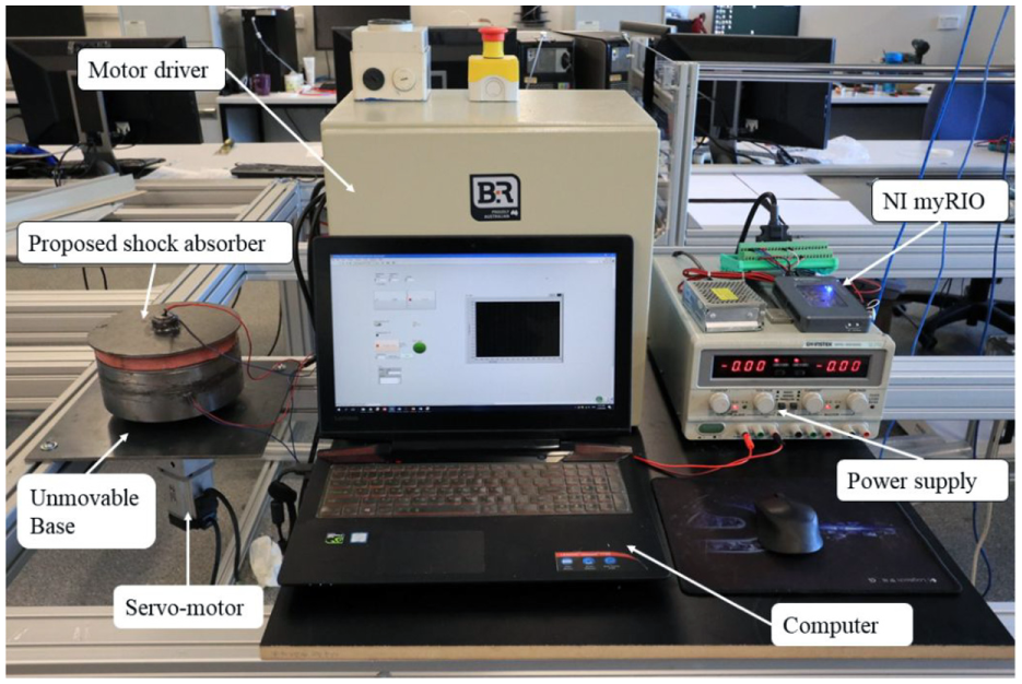
Schematic diagram of the experimental setup.
The testing cases consist of damping variability and stiffness variability. For each case, sufficient tests were measured in order to ensure performance stability and uniformity. As the damping variability is controlled by the internal damper current I1, the external damper current I2 was set as 0 A in the damping variability test case. Similarly, for the stiffness variability test cases, the internal damper current I1 was set as 0 A. The test input is selected as the sinusoidal signal
4. Testing results and analysis
4.1. Damping variability
4.1.1. Current dependency
Figure 4 shows the damping variability in response to various internal damper currents: I1 = 0, 0.2, 0.4, 0.6, 0.8 and 1.0 A, along with an amplitude A = 10°, frequency f = 0.5 Hz and external damper current I2 = 0 A. The calculated equivalent damping coefficient as plotted in Figure 4(b) was found using the following equation (Li et al., 2013)
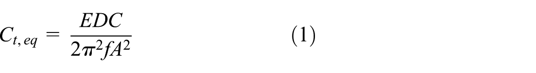
where
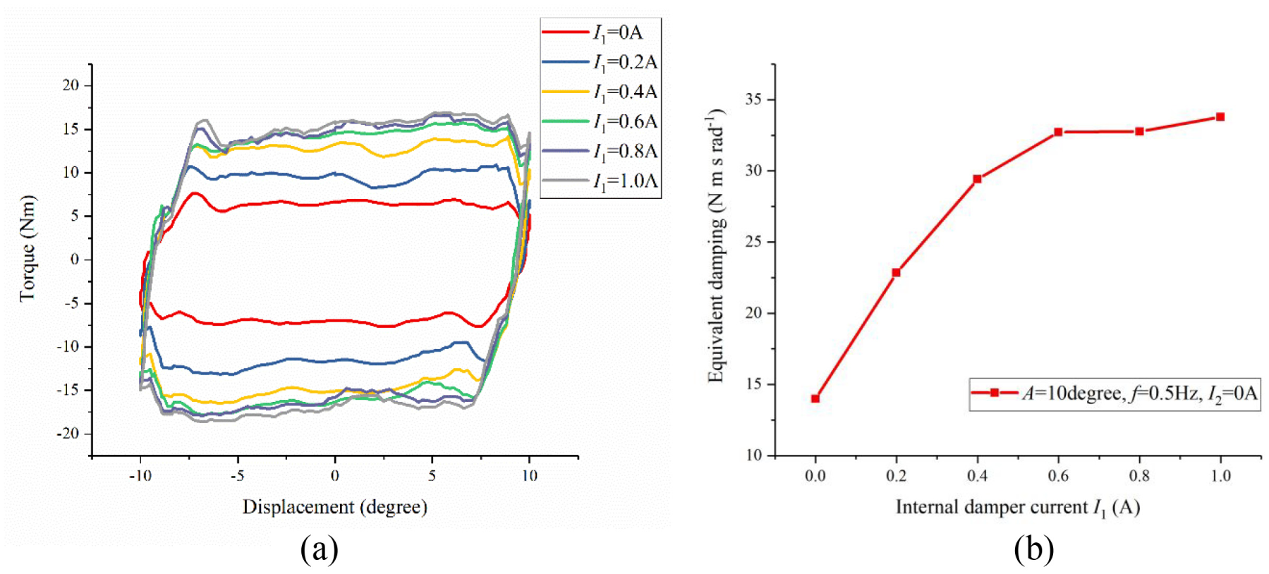
Variable damping behaviour under varied internal damper current I1. (a) Torque–displacement relation (A = 10°, f = 0.5 Hz, I2 = 0 A). (b) Equivalent damping coefficient to internal current I1.
As shown in Figure 4(a), the enclosed area of torque–displacement loops, EDC, increases with the increase in the internal damper current I1 from 0 to 1.0 A. The calculated equivalent damping coefficient in Figure 4(b) increases proportionally with all other variables held constant. This equivalent damping showed an increase of 141.6% from 13.98 to 33.78 N.m.s.rad−1 with the increase in current from 0 to 1.0 A. The peak torque, shown in Figure 4(a), begins to saturate when the applied current is larger than 0.6 A, which is consistent with the magnetic field saturation phenomenon in the magnetic field studies conducted, as shown in Figure 2.
4.1.2. Amplitude-dependent response
The amplitude dependent response of the damping variability at three amplitudes, A = 5°, 10° and 15°, under the combined conditions of internal damper current I1 = 1.0 A, frequency f = 0.5 Hz and external damper current I2 = 0 A is illustrated in Figure 5(a). The peak torque is almost the same for all the amplitude cases. Even though the energy dissipated in each loop, EDC, increases with the increasing current, the equivalent damping coefficient shows a decreasing trend in Figure 5(b) because the equivalent damping coefficient is inversely proportional to the square of amplitude, as shown in equation (1).
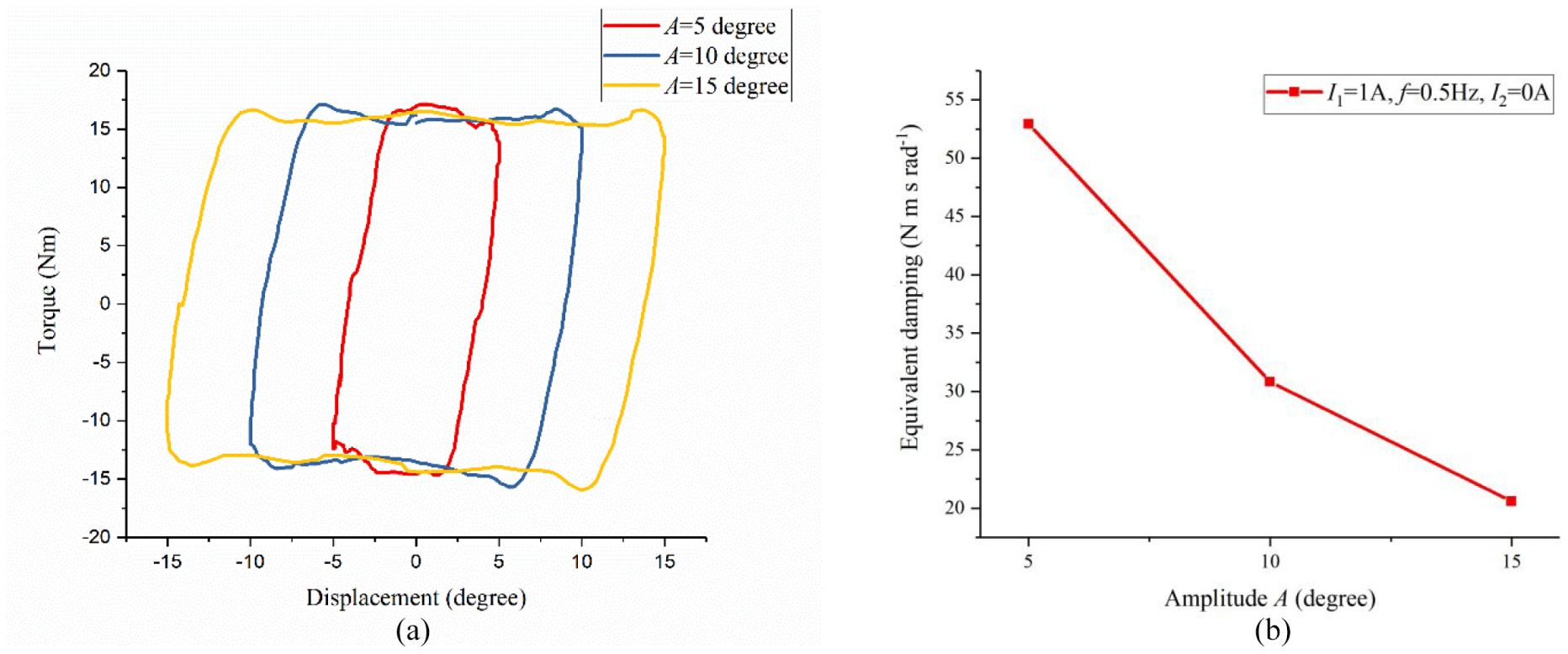
Response to different amplitudes (I1 = 1.0 A, f = 0.5 Hz, I2 = 0 A). (a) Torque–displacement relation. (b) Equivalent damping coefficient.
4.1.3. Frequency-dependent response
Figure 6 shows the response of the MR damper under the various loading frequencies: f = 0.5, 0.75 and 1.0 Hz, with the combined conditions of amplitude A = 10°, internal damper current I1 = 0.5 A and external damper current I2 = 0 A. It is noted that the peak torque of the enclosed area, EDC, is almost the same at three frequencies for all test cases. However, as it is indicated in Figure 6(b), the equivalent damping coefficient decreases with the increasing frequency f because the equivalent damping coefficient is inversely proportional to this.
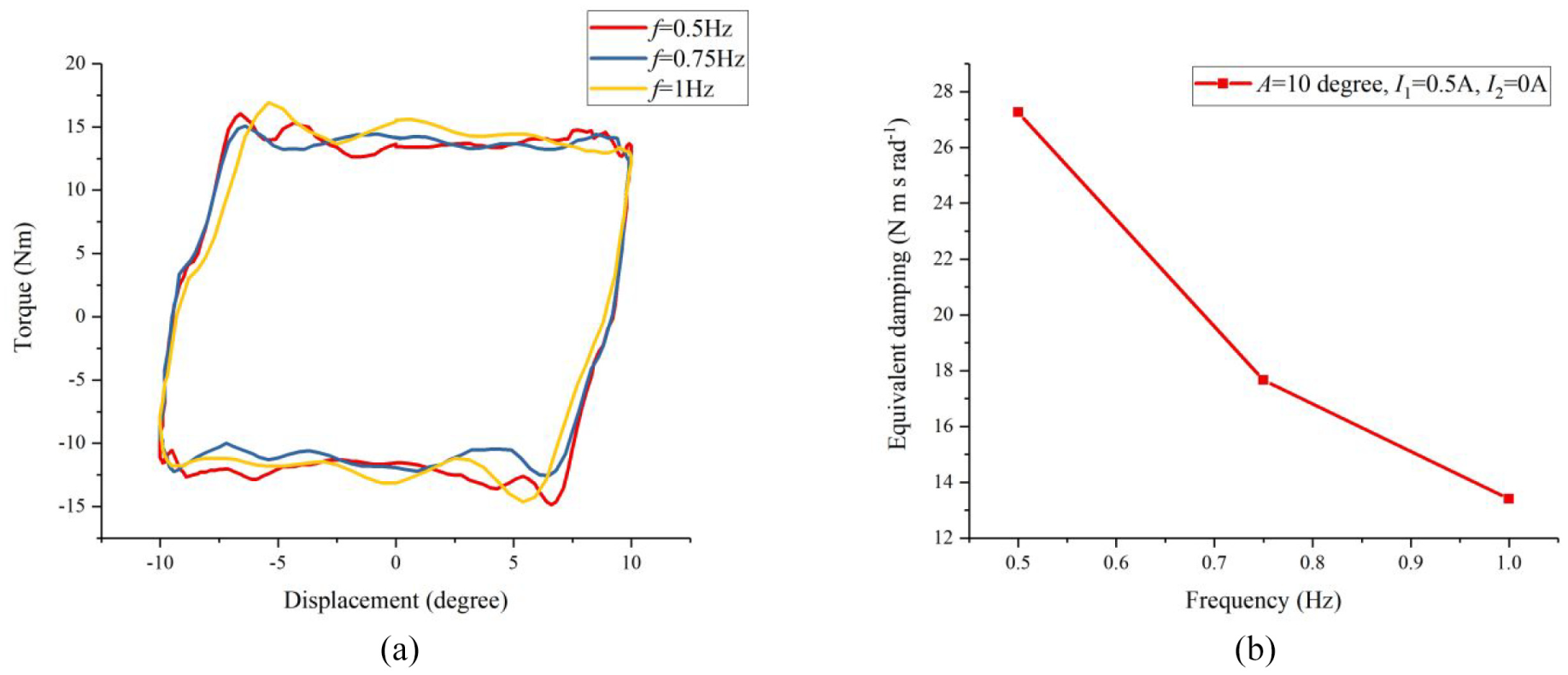
Response to different frequencies (A = 10°, I1 = 0.5 A, I2 = 0 A). (a) Torque–displacement relation. (b) Equivalent damping coefficient.
4.2. Stiffness variability
In this section, the stiffness variability of the designed damper is tested. Effective stiffness was calculated for all the test cases using the below equation (Li et al., 2013)

where
4.2.1. Current dependency
Figure 7 presents the stiffness variability of the damper under different levels of external damper current: I2 = 0, 0.5, 1.0, 1.5 and 2.0 A. Two sets of combined conditions, ‘A = 5°, f = 0.5 Hz, I1 = 0 A’ and ‘A = 10°, f = 0.5 Hz, I1 = 0 A’, were selected to illustrate the current-dependent behaviour for varied amplitudes.
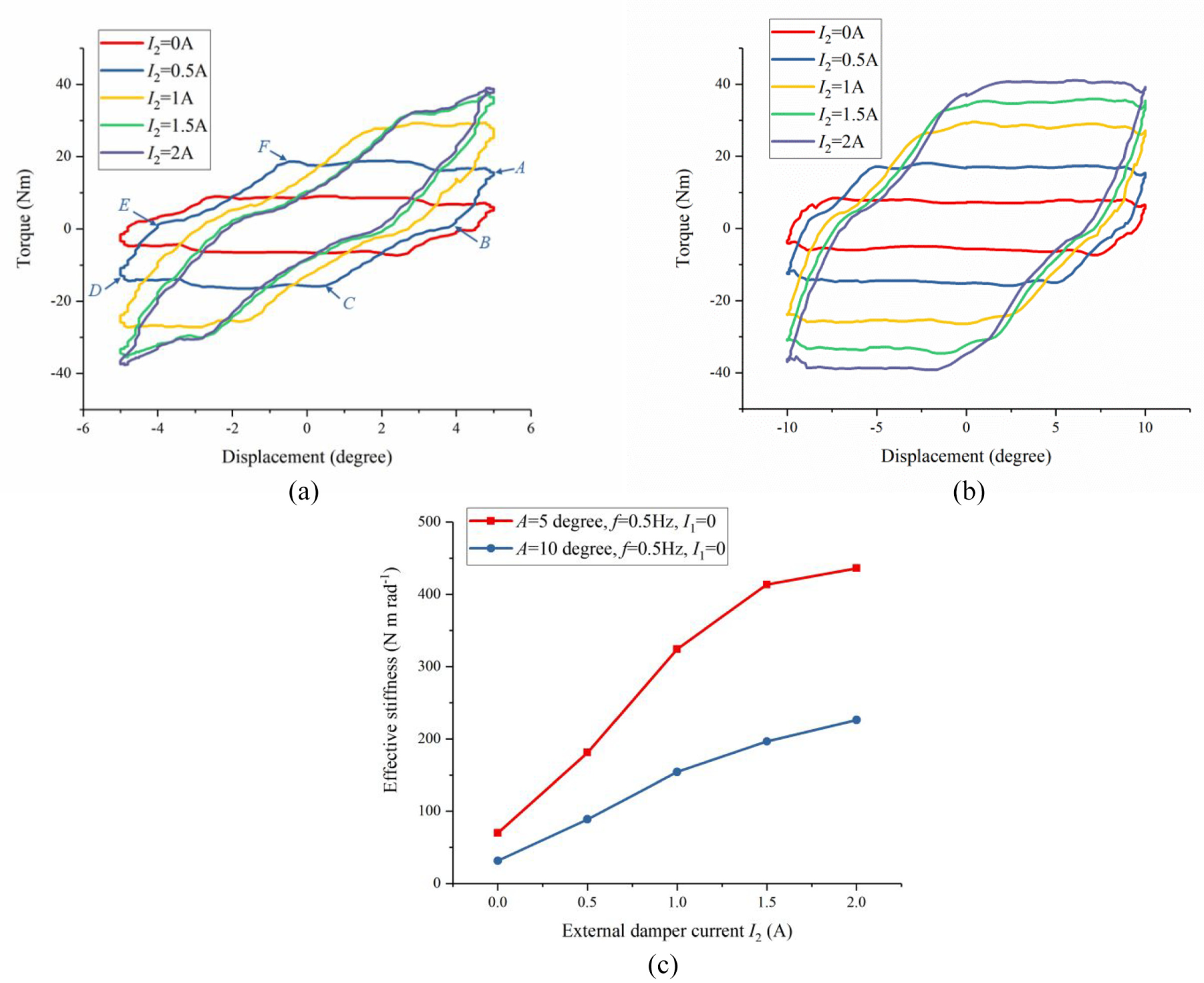
Variable stiffness under the varied external damping current I2. (a) Torque–displacement relation at small amplitude, A = 5° (f = 0.5 Hz, I1 = 0 A). (b) Torque–displacement relation at large amplitude, A = 10° (f = 0.5 Hz, I1 = 0 A). (c) Effective stiffness response for the two amplitude conditions, A = 5° and 10°.
As shown in Figure 7(a) and (b), the torque follows piecewise behaviour in response to a displacement input, with these loops being generated in a clockwise direction. Taking the test case of ‘A = 5°, f = 0.5 Hz, I1 = 0 A, I2 = 0 A’ in Figure 7(a) as an example, letters are placed about the figure at its vertices in a clockwise direction, starting with A at the maximum positive amplitude. Considering loading for
The effective stiffness of the damper is shown in Figure 7(c), as calculated using equation (2), which is simply the slope of the line AD. As illustrated, the stiffness of the designed damper increases with the increase in the external damper current I2 for both the test cases: ‘A = 5°, f = 0.5 Hz, I1 = 0 A’ and ‘A = 10°, f = 0.5 Hz, I1 = 0 A’. For the smaller amplitude of A = 5° condition, the stiffness increased 524% from 69.88 to 436.02 N.m.rad−1 as the current increased from 0 to 2 A. In the case of A = 10°, a 618.1% increase in effective stiffness from 31.51 to 226.26 N.m.rad−1 was achieved. The effective stiffness for the smaller amplitude A = 5° is larger than that of the A = 10° condition in general. This is simply due to the stiffness being an average across the entire displacement of the device, which includes more ‘zero-stiffness’ yielding of the external damper as displacement amplitude increases.
4.2.2. Amplitude-dependent response
Figure 8 illustrates the amplitude dependency of the damper for the three amplitude conditions, A = 5°, 10° and 15°. The results of two sets of the combined conditions, ‘I2 = 1 A, f = 0.5 Hz, I1 = 0 A’ and ‘I2 = 2 A, f = 0.5 Hz, I1 = 0 A’, are presented.
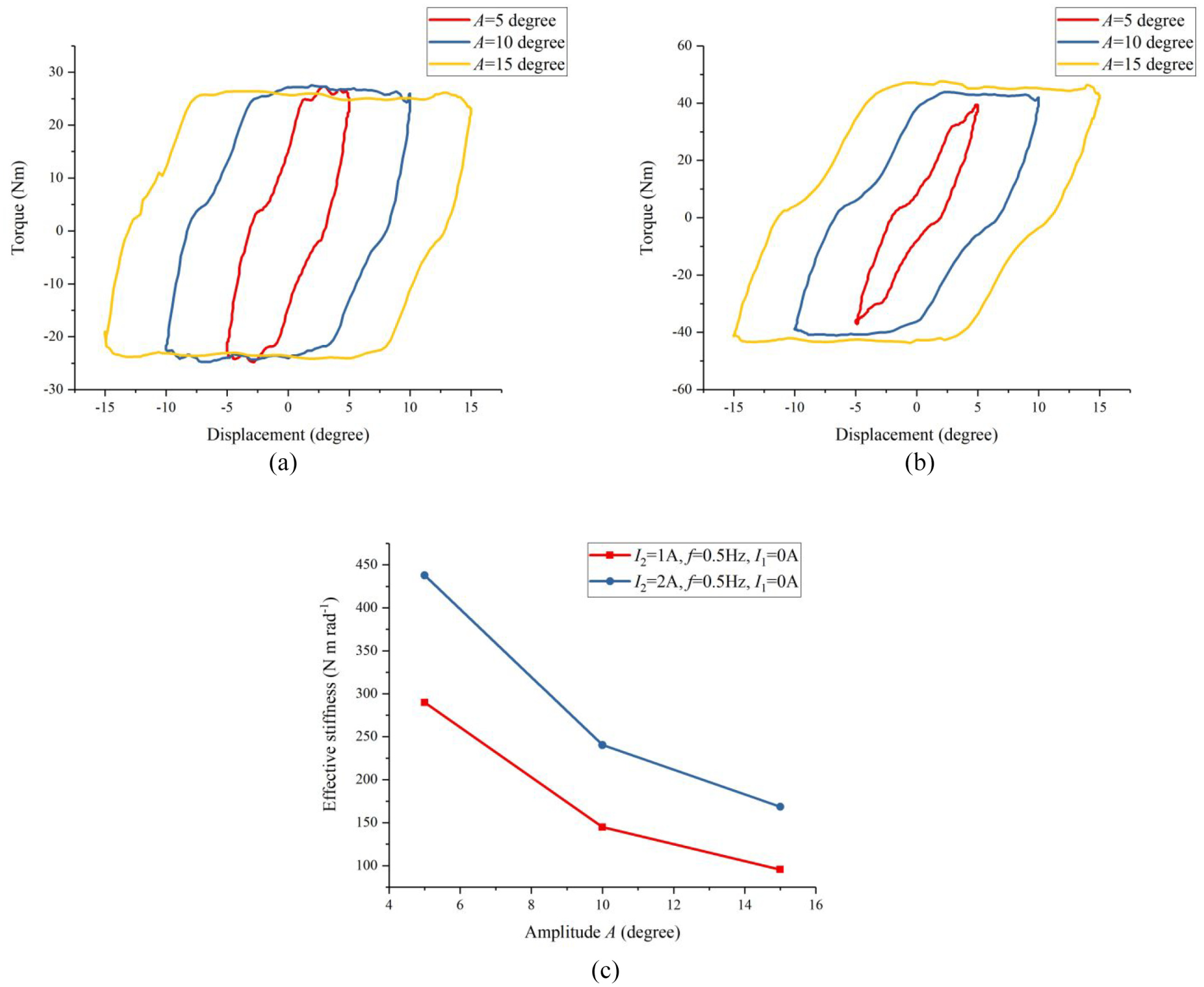
Stiffness response to various amplitudes. (a) Torque–displacement relation at small current I2 = 1 A (f = 0.5 Hz, I1 = 0 A). (b) Torque–displacement relation at big current I2 = 2 A (f = 0.5 Hz, I1 = 0 A). (c) Amplitude response of effective stiffness at the two current conditions, I2 = 1 A and 2 A.
In Figure 8(a), the external damper is yielded for all the amplitude cases at the lower current I2 = 1 A. The damping torque generated by the low current I2 = 1 A is not sufficient to prevent yielding even for the smallest amplitude of A = 5°. In contrast, as shown in Figure 8(b), the external damper is not yielded for the amplitude A = 5° case when a higher current I2 = 2 A is applied until the amplitude increased to A = 10°. Consequently, the maximum torque of the amplitude A = 5° is slightly smaller than that of A = 7.5° and 10°, as in this case, the constant yielding torque of the damper was not reached by the spring for this given external damper current and test frequency.
The effective stiffness of these tests is illustrated in Figure 8(c), which reveals a declining trend with increasing amplitude. Under a constant amplitude, because the maximum torque of the larger external damper current condition I2 = 2 A is larger than that of the smaller current condition I2 = 1 A, the effective stiffness of the large current conditions is larger than that of the smaller current conditions.
4.2.3. Frequency-dependent response
Figure 9 provides the frequency-dependent response of the proposed damper. Three frequencies f = 0.5, 0.75 and 1.0 Hz are prescribed for the test cases of ‘I2 = 1 A, A = 5°, I1 = 0 A’ and ‘I2 = 1 A, A = 10°, I1 = 0 A’. Relative movement between the external damper casing and the external damper disc exists at both amplitude conditions. The torque–displacement loops are almost the same at the three frequency conditions for both the smaller and the larger amplitude test cases. Thus, the effective stiffness is also almost the same for all the frequency conditions as illustrated in Figure 9(c).
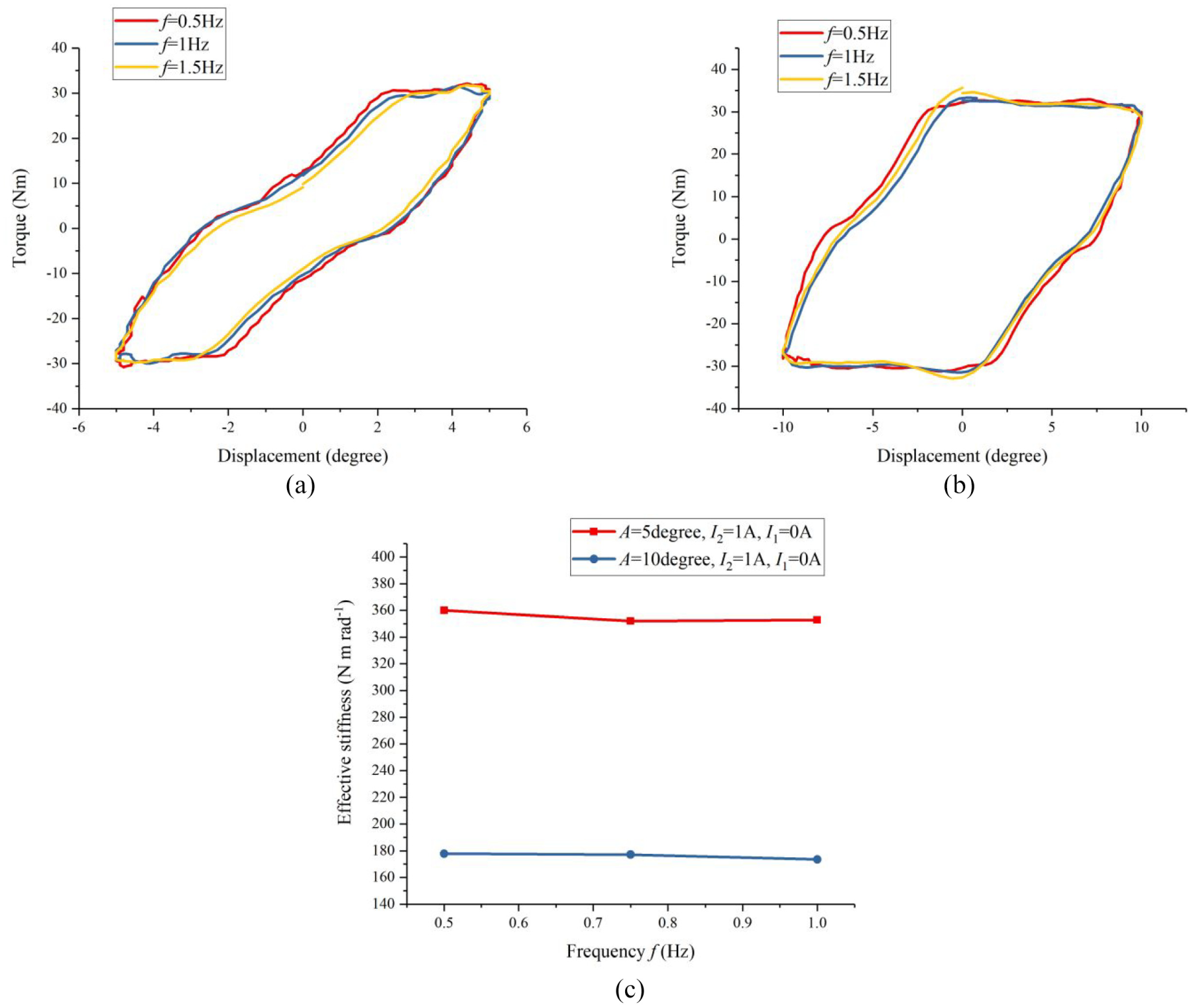
Stiffness response to various frequencies. (a) Torque–displacement relation at small amplitude A = 5° (I2 = 1 A, I1 = 0 A). (b) Torque–displacement relation at big amplitude A = 10° (I2 = 1 A, I1 = 0 A). (c) Frequency response of effective stiffness at two amplitude conditions, A = 5° and 10°.
4.3. Simultaneous working of internal and external damping units
Figure 10 presents the test results when the internal damper unit and the external damper unit work together. The external damper current I2 is set as 0 and 2 A for two groups of test separately. In each group, internal damper current I1 is applied with three levels of currents, 0, 0.5 and 1 A. When the external damper current I2 = 2 A, the maximum torque shows an increase from 42.3 to 52.08 Nm as the internal damper current I1 increases from 0 to 1 A. This increasing trend is quite similar to that of the reference group in which the external damper current I2 = 0 A.
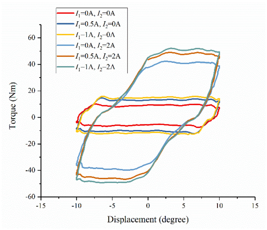
Simultaneous working of internal and external damping units.
5. Modelling and the parameter identification
In order to predict the variable damping and stiffness behaviour of the designed shock absorber, a mathematical model is established in this section. The parameters for both the internal damping unit and the external damping unit were also identified as follows.
5.1. Model establishment
As it is shown in Figure 11, a mathematical model which incorporates two Bingham components (Spencer et al., 1997) is built to predict the damping and the stiffness variation of the designed MR damper. A Coulomb friction element T1 in parallel with a dashpot with viscous damping coefficient c1 is used to describe the internal MR damper unit. Similarly, the external damper unit is characterised by another Coulomb friction element T2 in parallel with a dashpot with viscous damping coefficient c2. In addition, stiffness kr represents that of the rubber spring. For these parameters, T1 and c1 are controlled by the applied current to the internal damper I1, while T2 and c2 vary in value due to the change in external damper current I2. The angular displacements of the shaft or plate and the external damper casing are prescribed as
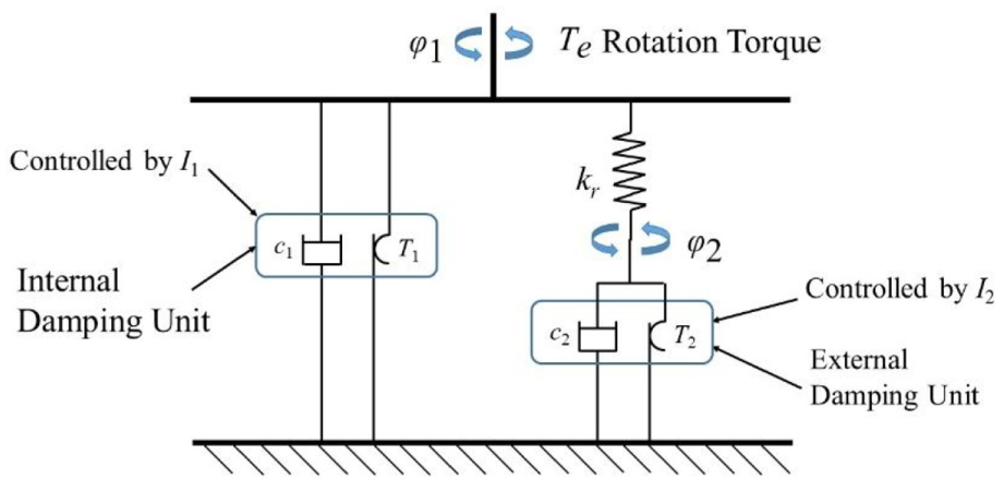
Mathematical model of the proposed rotary MR damper.
The rotation torque


where

The damper torques
If

Else if

5.2. Parameter identification
After building the model of the system, four parameters in the model, c1, T1, c2 and T2, should be identified using the experimental data to predict the behaviour of the device. The procedure follows the least-squares method in combination with the trust-region-reflective algorithm which is available in the MATLAB and Simulink. The goal of this method is to minimise the difference between the modelled results and the experimental results by adjusting the four parameters as shown in the following equation
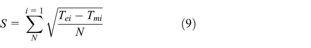
where S is the root mean square between the predicted and the experimental results;
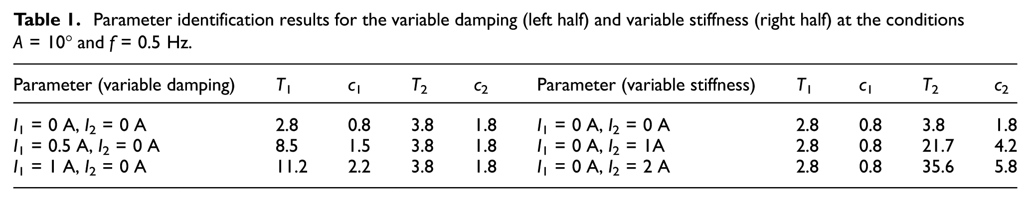
As the damping variability and the stiffness variability are separately controlled by the internal damper current I1 and the external damper current I2, the internal damper parameters c1 and T1 at different currents are identified with the fixed external damper parameters c2 and T2 for the damping variable part, and vice versa. Adopting the experimental data of variable damping tests (A = 10°, f = 0.5 Hz, I1 = 0 A, 0.5 A and 1 A) and the data of variable stiffness tests (A = 10°, f = 0.5 Hz, I2 = 0 A, 1 A and 2 A), the parameters are identified using the builded model in the Simulink as shown in Table 1. The modelled results compared with the experimental results are also shown in Figures 12 and 13.
Parameter identification results for the variable damping (left half) and variable stiffness (right half) at the conditions A = 10° and f = 0.5 Hz.
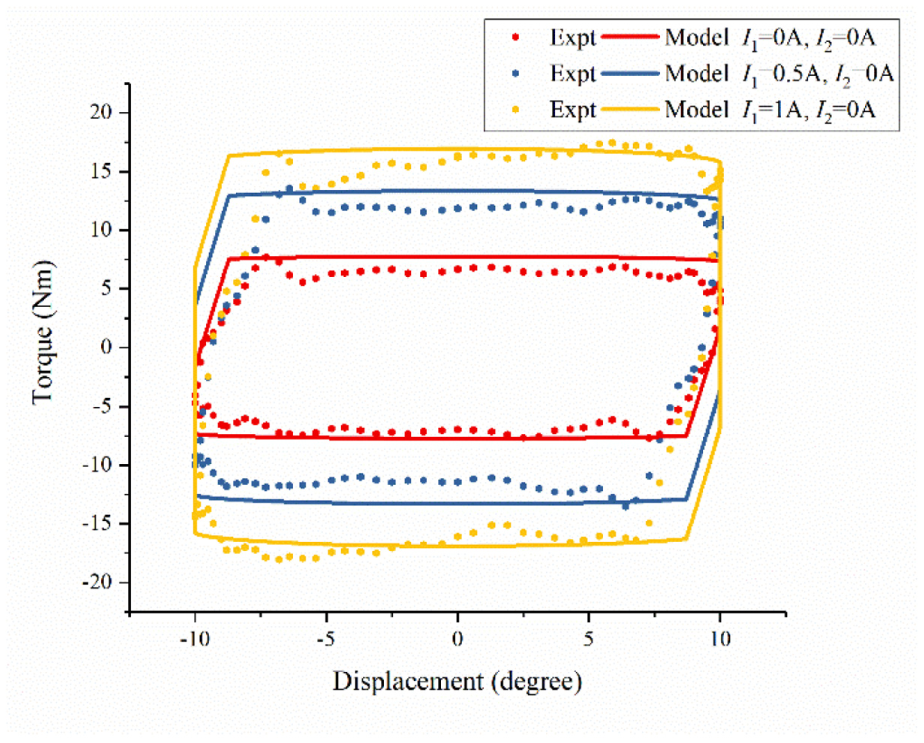
Modelled results compared to the experimental results of the variable damping tests (A = 10°, f = 0.5 Hz).
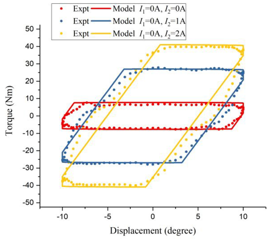
Modelled results compare to the experimental results of the variable stiffness tests (A = 10°, f = 0.5 Hz).
As illustrated in the left half of Table 1, the external damper parameters T1 and c1 increase with an increasing internal damper current I1, while T2 and c2 are constant with the constant zero external damper current I2. Plotting the simulated result against the experimental result, the modelled variable damping behaviour in Figure 12 shows a good fit with the experimental data at various levels of I1. For the modelled results, the area enclosed by the torque–displacement loop increases with the increasing current, which predicts the variable damping ability very well. The parameters of the external damper, T2 and c2, also show a positive relationship with the increase in I2. At the same time, the internal damper parameters T1 and c1 do not change for the fixed I1. The variable stiffness capability is also well modelled for the effective stiffness increases with the increasing I2, as shown in Figure 13.
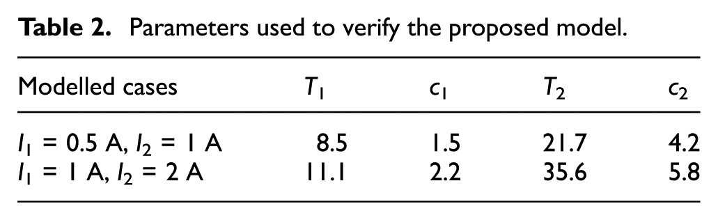
To verify that the proposed model with the identified parameters could predict the behaviours of the device, two modelled results for the conditions ‘I1 = 0.5 A, I2 = 1 A’ and ‘I1 = 1 A, I2 = 2 A’ were plotted in Figure 14 using the parameters shown in Table 2. The values of T1 and c1 are obtained from the cases with the same internal damper current I1, while the values of T2 and c2 are obtained from the cases with the same external damper current I2. For instance, within the parameters for the modelled case ‘I1 = 0.5 A, I2 = 1 A’, ‘T1 = 8.5, c1 = 1.5’ and ‘T2 = 21.7, c2 = 4.2’ are separately obtained from the corresponding parameters of the test cases of ‘I1 = 0.5 A, I2 = 0 A’ and ‘I1 = 0 A, I2 = 1 A’ as listed in Table 1. As it is shown in Figure 14, the modelled results have a very good accordance to the experimental data, which means the proposed model with the parameters in Table 2 could predict the behaviour of the device very well, facilitating future control efforts for such a device.
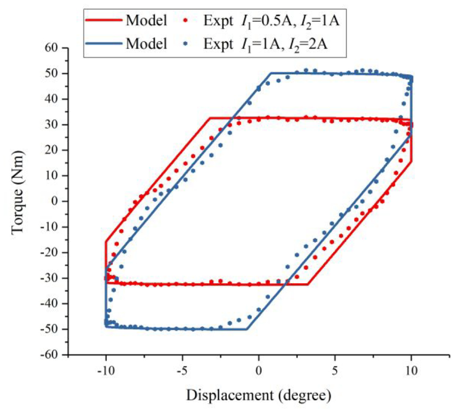
Verification of the proposed model under co-working conditions by comparing the modelled results to the experimental results (A = 10°, f = 0.5 Hz).
Parameters used to verify the proposed model.
6. Discussion
In this article, a rotary variable stiffness and damping is designed, tested and modelled. Even though the proposed shock absorber could realise independent control of variable damping and stiffness, it still has drawbacks such as magnetic saturation as mentioned in Section 2.3. This issue could be solved by further optimization of the internal damper, which may contribute a larger damping variation. In addition, the shock absorber would be more versatile in application if it had a more compact structure.
7. Conclusion
This study includes the design of a novel shock absorber with variable damping and stiffness capabilities based on rotary MR damper. Experimental tests were conducted to verify such performance, and the test results show that the damping increased 141.6% from 13.98 to 33.78 N.m.s.rad−1 as the current increased from 0 to 1.0 A with a 10° amplitude. In addition, a maximum of 618.1% increase in effective stiffness from 31.51 to 226.26 N.m.rad−1 is achieved with the current shift from 0 to 2 A at the amplitude of 10°. The accuracy of the established mathematical model in predicting the variable damping and stiffness characteristics of the damper was also verified with the identified parameters of internal and external MR dampers.
Footnotes
Declaration of conflicting interests
The author(s) declared no potential conflicts of interest with respect to the research, authorship and/or publication of this article.
Funding
The author(s) disclosed receipt of the following financial support for the research, authorship, and/or publication of this article: This research was supported by the Australian Research Council Linkage Grants (nos LP160100132 and LP150100040), Discovery Grant (no. DP150102636), National Natural Science Foundation of China (no. 51375468) and has been conducted with the support of the University of Wollongong and China Scholarship Council joint scholarship.