
Abstract
For sound absorption of conventional porous materials, its noise-reducing ability in low frequencies is less than that in high frequency bands. A porous layer offers effective sound absorption when the thickness of layer is a quarter wavelength of the sound wave. Increasing the layer thickness is not an effective solution. Adjustment of rear air cavity volume for the porous medium has been used in practical applications to increase low frequency sound absorption. Noise reduction using only passive sound absorption characteristics is a challenge, especially when the operation conditions of noise source changes. In this study, we propose a smart porous material having noise reduction ability in the broad frequency band. We implement semi-active control by applying a magnetic reactive material to a porous medium. The smart foam proposed in this study reduced noise with adjustment of the magnitude and polarity of the magnetic field. Evaluation of its noise reduction performance is performed with the impedance tube method. Experiments are conducted for semi-active noise control of the proposed smart foam. The sound absorption characteristics are controlled efficiently with relatively low electric power consumption. A theoretical model to predict absorption characteristics is proposed using the transfer-matrix method, and its results show good agreement with measured behaviors.
1. Introduction
Porous structures are commonly used in noise-reducing applications because of their light weight, low production cost, and flexible mechanical characteristics. The acoustic properties of porous structures are determined by various microscale characteristics including flow resistivity, porosity, tortuosity, and characteristic length (Allard and Atalla, 2009; Doutres et al., 2010). These factors reflect mechanical and acoustical properties. For noise sources such as vehicles, refrigerators, and washing machines, the noise spectral characteristics change with the operating conditions. Conventional passive sound absorbers do not allow active adjustments. Previous studies have been carried out to implement a sound-absorbing structure with an active control system that dynamically responds to the time varying characteristics of noise sources.
Smart foams combining the passive sound absorption characteristic of a porous structure with the active control of a piezoelectric material were proposed. A smart structure composed of cylindrically curved polyvinylidene fluoride (PVDF) film embedded in a partially reticulated polyurethane acoustic foam was proposed (Gentry et al., 1997), and active noise control with a feedforward filtered-x LMS controller was implemented. The potential of a single-input single-output (SISO) adaptive feedforward and feedback methods with smart foams was investigated (Guigou and Fuller, 1998). The adaptive feedback control system showed efficient noise reduction. To improve the transmission loss with small thickness, smart foams composed of PVDF film and half-cylinder-shaped melamine foam were investigated (Kundu and Berry, 2011). Significant improvement in noise reduction capability was obtained at specific frequencies. The curvature of the PVDF membrane in the proposed structure was an important factor in controlling low frequency band noise. The curved PVDF structure was also utilized as a speaker for active noise control of automotive interior noise (Dias et al., 2007). The adaptive-passive noise control methods by combining a passive porous material with a noise reduction structure such as the Helmholtz resonator (De Bedout et al., 1997; Esteve and Johnson, 2005) were proposed with adaptive control systems. Hybrid noise control for duct (Kostek and Franchek, 2000; Sellen et al., 2006) and fan noise (Wong and et al, 2003) by combining the passive and active noise control methods were investigated. Adaptive control methods for the rear air cavity of porous structures (Beyene and Burdisso, 1997) and microperforated panels (Cobo et al., 2004; Yoda and Konishi, 2001) were proposed to change their passive acoustic characteristics. Smart foams with magnetorheological materials within a magnetic field have been studied (Gong et al., 2013). Methods for improving the absorption characteristics of passive porous materials through magnetic field control were proposed (Scarpa and Smith, 2004; Zielinski and Rak, 2010).
In this study, a sound-absorbing structure that changes acoustic characteristics using the external magnetic field is presented. The proposed structure was constructed with the thin layer material rolled in helical shape. The magnet was placed at the center, and it imposed deformation force when the external magnetic field was applied to the foam. Due to the rolled shape, the force induced change of the thickness. The slits between the thin layers absorb sound waves during propagation. The slit length in the proposed structure varied actively according to the magnetic field. The variation in the length induced control of the sound absorption characteristic. To verify the performance of the proposed structure, the absorption coefficient was measured with the impedance tube method. The transfer-matrix method was used to identify the sound absorption variation under different magnitudes of the magnetic field. The absorption mechanism of the proposed smart structure was verified by comparing it with the predicted results.
2. Design and fabrication of smart foam
In the case of conventional sound-absorbing materials such as polyurethane and melamine foams, material properties are determined by their microstructures. Figure 1 shows the proposed smart porous structure for intelligent control of the acoustic properties. The magnetic material is located at the center of the structure. A thin layered material (mulberry paper in this study) constitutes the porous medium. Due to the interaction between the structure and air during propagation, the thin layered medium absorbs sound energy and converts it into heat. The slit geometry of the proposed structure determines the porosity and flow resistivity (Kim et al., 2015). Air medium between adjacent layers determines acoustic characteristics. The thickness of this air layer depends on the winding process. A specific slit thickness induced the optimum sound absorption, which is correlated to the porous properties.
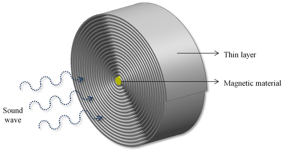
Configuration of the proposed smart porous structure.
The geometric change of the proposed structure in response to the magnetic field is shown in Figure 2. The direction of wave propagation relative to the surface is normal to the sample surface. The sound absorption characteristics of the proposed structure are affected by inherent material properties, which are determined by its producing parameters. When a magnetic field acting parallel to the thickness direction is applied to the proposed structure, the surface of the helical absorber is deformed into a curved shape, as shown in Figure 2(b). This process increases the edge-to-edge thickness of the smart foam to Δlh + lh and expands the effective absorption thickness. The increased thickness enhances the sound absorption, especially at a low frequency band. Thereby, active control of the acoustic characteristics of proposed porous medium was possible. The magnitude of the magnetic flux controls the direction of curvature of the proposed structure according to the polarity of the magnetic field. The rear air cavity layer, la, at the back of the smart foam, also raises the sound absorption performance in low frequency bands.
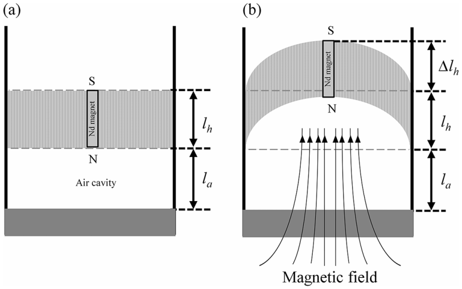
Schematics of the proposed structure: (a) without and (b) with application of the magnetic fields.
3. Experimental setup to measure acoustic properties
The impedance tube method was used to evaluate the acoustic characteristics of the proposed smart foam, as shown in Figure 3. The two pressure-field microphones (B&K Type 4187) were mounted along the wall of the tube. A loudspeaker was placed at one end of the tube to generate a random sound signal. A power amplifier (B&K Type 2719) was used to drive the loudspeaker. The distance between the microphones was 20 mm, which determines the lower cut-off frequency as 500 Hz. The upper cut-off frequency is set as 6400 Hz, which is controlled by the tube diameter (29 mm in this study). A solenoid coil was placed at the end of the tube, and the inner diameter of the coil was the same as that of the tube. A rigid termination was given at the end of the solenoid coil. A direct current (DC) power supply (TOYOTECH TDP-305A) was connected to the solenoid coil to generate a DC magnetic field. The absorption coefficient was measured by calculating the pressure amplitudes of the incident and reflected standing waves. Measurements were performed under different DC magnetic field amplitudes. Neodymium magnets (4 mm × 4 mm) were used for smart foam materials of different depths (lh).
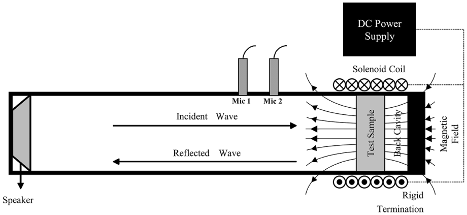
Schematic of experimental setup for sound absorption coefficient measurements.
4. Prediction of acoustic behaviors for multilayer structure
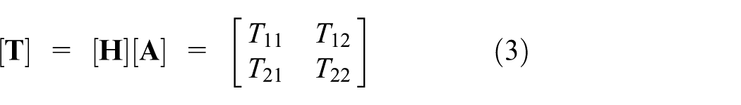
The proposed smart foam had multiple layers and was constructed with a helical sound-absorbing structure and an air cavity behind the porous medium. To predict the acoustic characteristics of a multilayer structure, the transfer-matrix method and the equivalent electrical circuit approach (EECA) method (Kang and Fuchs, 1999) have been widely used. In this study, the transfer-matrix method (Lee and Kwon, 2004) was used to predict the absorption behavior of the proposed smart foam. A schematic diagram for a transfer-matrix representation is shown in Figure 4. The transfer matrix for the helical absorber, [
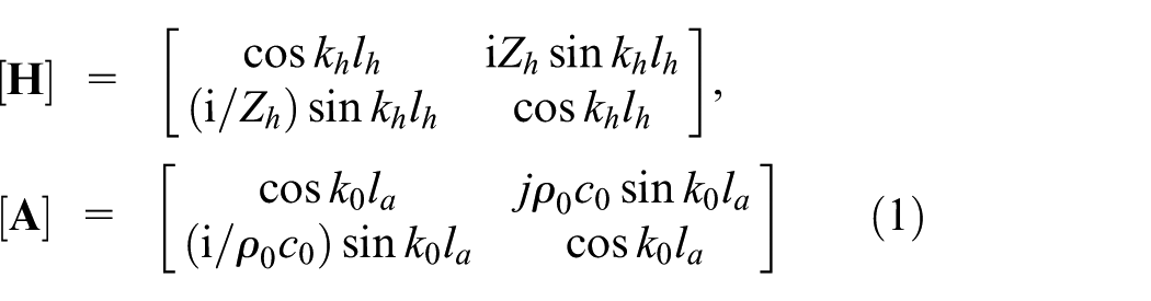
where k0, ρ0, and c0 are the wavenumber, density, and wave speed of air, respectively. A parallel-sided slit model (Allard and Atalla, 2009) was used to predict the acoustical properties of the helical-shaped sound absorber. The thin layer constructed as helical shapes was analyzed as a rigid wall. The area occupied by the magnet in the sound medium was approximately 2% of that of the helical structure. It did not substantially affect the passive acoustic characteristics of the porous structure. Consequently, the magnet was neglected during prediction of the acoustic properties. The wavenumber, kh, and characteristic impedance, Zh, of the helical absorber were calculated with the effective density, ρh, and bulk modulus, Kh, of the slit model (Allard and Atalla, 2009; Kim et al., 2015) as kh = ω(ρh/Kh)0.5 and (ρh·Kh)0.5. The density and modulus were expressed as
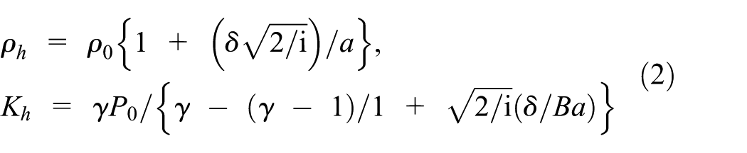
where γ, B, P0, and a are the specific heat ratio, square root of the Prandtl number, atmospheric pressure, and slit thickness, respectively. The acoustic characteristics depended on the pore size, a. This factor was controlled during the winding process of sample fabrications. The value of a decreased with the increasing production layer length. It was calculated considering the layer thickness and the absorption area, which varies according to the layer length of helical absorber. The viscous skin depth, δ = (2η/ωρ0)0.5, where η is the shear viscosity, also influenced the sound absorption. The total transfer matrix, [
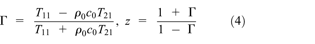
By applying the rigid wall boundary condition, the pressure reflection coefficient, Г = B/A, and surface acoustic impedance, z = zr + izi, are expressed as
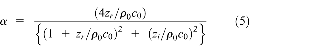
The sound absorption coefficient, α, is defined by α = 1–|Г|2. For the proposed smart foam, the absorption coefficient was given in terms of surface acoustic impedance as follows
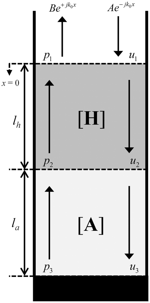
Configuration of transfer matrices for prediction of acoustic properties of proposed smart foam.
5. Measured acoustic properties and comparison with predictions
The measured sound absorption coefficients in the absence of a rear air cavity are shown in Figure 5(a). Mulberry paper was used for the thin layer of the helical absorber. The material density was 80 kg/m3. The magnitude of the DC magnetic field increased according to the input voltage, V. The sound absorption enhanced with the increasing magnitude of the magnetic field.
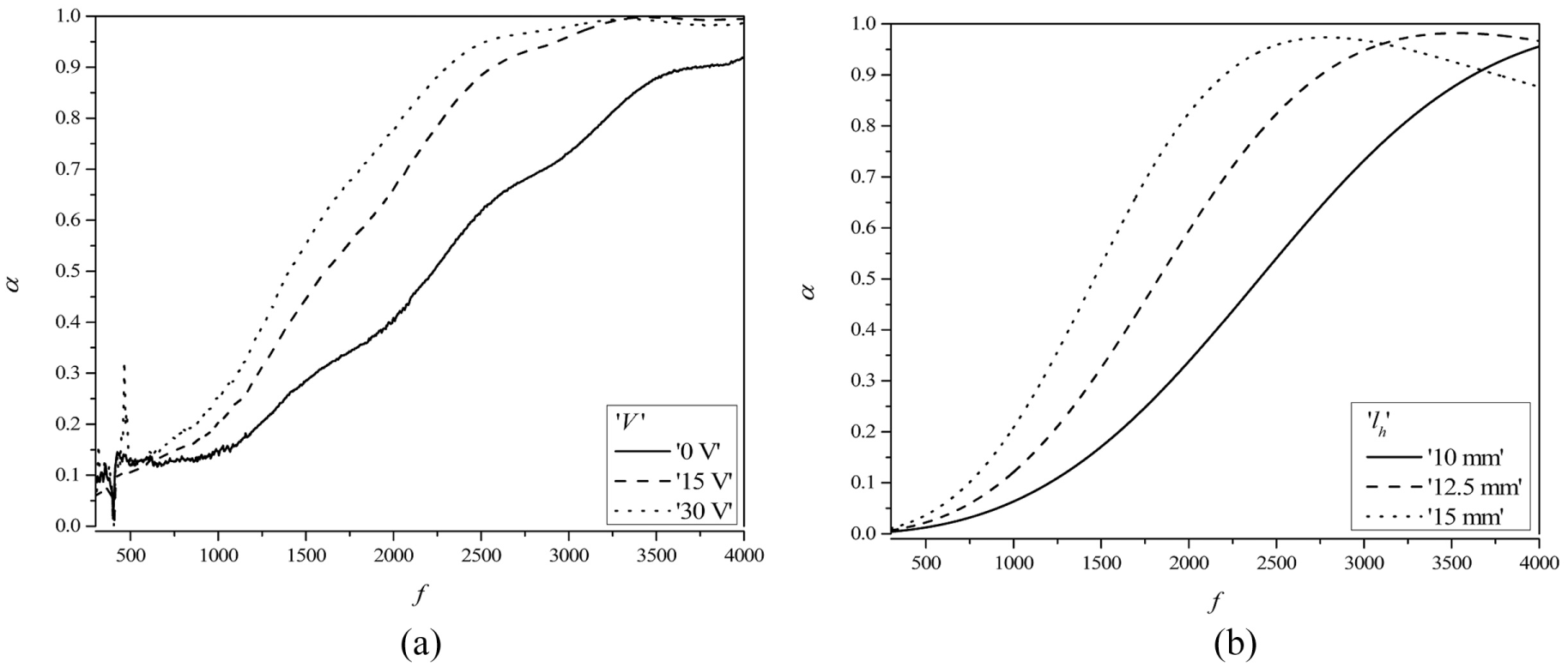
(a) Measured and (b) predicted sound absorption coefficients.
This increased sound absorption behavior showed similar behavior to those expected for acoustic foams with larger thickness. For comparison of the measured results, the predicted sound absorption coefficients derived by equation 5 for foams of different thicknesses were compared, as shown in Figure 5(b). In the predicted results, the larger dissipation due to the thickness of the helical absorber was consistent with the measured results. This confirms that the magnetic field induced change of the effective thickness of the smart foam and controls the sound absorption characteristics.
In the deformed shape, due to the magnetic fields, the rear air cavity increased in volume together with the increased thickness. The comparison with the prediction of the actual sound absorption verifies the influence of the magnetic field on the effective thickness variation. The edge-to-edge thickness of the deformed smart foam increased by 33 mm when the input voltage was 30 V. The predicted results yielded similar sound absorption properties as the measured sound absorption was for the foam of 15 mm thickness. When the smart foam was deformed in the thickness direction, the structure interacted with the air layer in the helical absorber medium. To predict the acoustic properties of the smart foam deformed by the magnetic field, the predicted absorption coefficient was derived after varying the thickness factor which best reflects the change of the sound absorption characteristic. The increased effective thickness according to the voltage input is shown in Figure 6, which confirmed control of the foam geometric properties by the magnetic field.
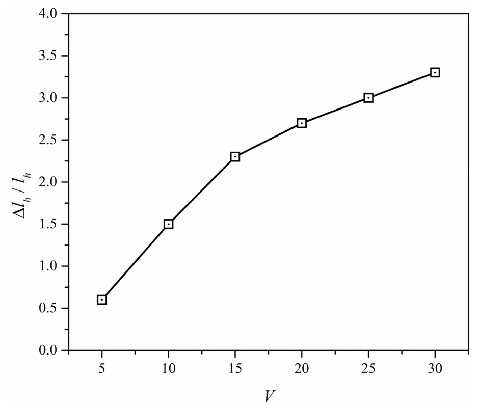
Increased thickness ratio according to the applied voltage variations.
The contour graphs in Figure 7 show the measured and predicted sound absorption coefficient when there is a rear air cavity. The measured and predicted results showed that the frequency band of the maximum absorption decreased with the increasing effective thickness. For the proposed smart foam, the frequency band of maximum sound absorption was controlled by more than 300 Hz by a relatively small voltage input. The maximum sound absorption appeared at a lower frequency band than those without the rear air layer. The proposed structure showed a complete sound absorption without reflections at low frequencies. With the increasing DC magnetic field magnitude, the maximum absorption coefficient became slightly smaller than those without the magnetic field. It was possible to control the sound-absorbing frequency band according to the magnitude of the magnetic field, as shown in Figure 5. In Figure 7(a) and (b), there was a linear correlation between the predicted thickness, lh, and the input voltage, V, as shown in Figure 6.
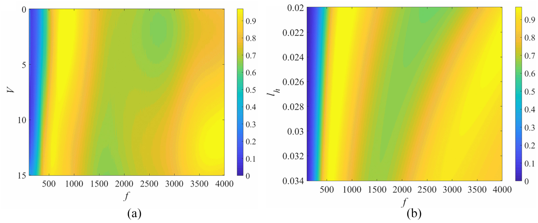
(a) Measured and (b) predicted sound absorption coefficients for different thickness and voltage inputs for lh = 20 mm, la = 30 mm, and a = 0.009 mm.
A slight deviation was shown in the 2000–3000 Hz band. This deviation appeared since the change of the curvature shape of smart foam was neglected during predictions. In order to simplify the influencing factor, the prediction was performed using the effective thickness. In Figure 7(a), sound absorption characteristics measured for input voltage of 10 V were found to be inconsistent with the predicted results. In the actual fabrication of the helical absorber, no continuous air layer forms. Some layers were in contact with each other due to inhomogeneity. A frictional force exists between the layers when static force is produced by the magnetic field. As the static force is smaller than the maximum static frictional force in some areas, the deformation efficiency of the helically shaped smart foam was lowered. Mulberry paper, which has smaller friction coefficient than conventional paper, was used to make a helical absorber in order to prevent these restrictions. If the layer material has a smaller friction coefficient and thickness than that used for construction of the helical absorber in this study, it is possible to obtain higher sound absorption efficiency in the lower frequency band.
6. Conclusion
In this study, a smart foam structure that changes sound-absorbing properties reactively and effectively with a DC magnetic field is proposed. Its absorption characteristics were predicted to confirm the principle of sound reduction. With the proposed smart foam structure, it was possible to control the effective sound absorption characteristics by supplying relatively low electric power inputs. To predict the acoustical behavior of the proposed smart structure, the transfer-matrix method was used. The measured and predicted results show good agreement for the two different absorber configurations—with and without the rear air cavity. The maximum sound absorption appeared at a lower frequency when there is a rear air cavity. The sound absorption characteristic was controlled by the magnetic field. The effective thickness of the proposed smart foam was adjusted with the solenoid coil. A layer material with a low friction coefficient improves the adaptation capability for the proposed structure. This adjustment induced adaptive change of sound absorption characteristics, which is required for efficient reduction of noise having variations on the spectral characteristics depending on operation conditions. The proposed structure allows modification of sound reduction characteristics by incorporating relatively simple electronic devices. Consequently, wide applications are expected, for examples, noise barriers and room acoustic fields. When the proposed structure is applied to wall surfaces, reverberation characteristics are adaptively adjusted according to the required acoustic conditions depending on usage of the room spaces.
Footnotes
Declaration of conflicting interests
The author(s) declared no potential conflicts of interest with respect to the research, authorship, and/or publication of this article.
Funding
The author(s) disclosed receipt of the following financial support for the research, authorship, and/or publication of this article: The research was supported by the Basic Science Research Program through the National Research Foundation of Korea (NRF), which is funded by the Ministry of Education, Science, and Technology (NRF-2019R1A2C1005619).