
Abstract
The demand of more powerful and high-dynamic hydraulic actuators gives the servo valve as a control member an increasingly important role. The valve should provide the hydraulic actuator with sufficient volume flow over wide frequency range to achieve large strains at high operating frequencies. Here, the electrorheological effect as an electrohydraulic valve drive offers great potential. It converts the electrical input signal directly into a controlling mechanical quantity within a few milliseconds and provides theoretically unlimited strain. Thus, the electrorheological effect has the ability to increase the performance of conventional hydraulic systems. This work presents a two-stage servo valve with an electrorheological pilot stage. Furthermore, it introduces a model to describe the static and dynamic properties of the system. The model is validated on the basis of measurement results.
1. Introduction
Hydraulic linear actuators offer the advantage of very high power density combined with simple implementation of translatory movements with almost unlimited strain (Huber et al., 1997). These properties are the reason for their successful application in many technical areas, such as aerospace, material testing, and vibration decoupling (Maskrey and Thayer, 1978). Here, servo valves represent a key component, as they form the interface between the fluid power unit and the electronic control system (Janocha, 2004; Plummer, 2016). Proportional to the electrical input signal, they release volume flow to the actuator. As a result, its dynamic is a function of the valve response time and the flow rate. The performance of hydraulic drives is therefore mainly dominated by the static and dynamic characteristics of the servo valves used (Changbin and Zongxia, 2014). Here, the conventional servo valves set the limiting factor. They often consist of two stages, an electromagnetic and a mechanical-hydraulic converter in the pilot stage and a valve spool in the main stage (Gordic et al., 2008; Moog, 1956). The mechanical-hydraulic converter represents two active hydraulic flow resistances usually designed as a flapper between two nozzles. The electromagnetic converters used, usually torque motors, generate small strokes only due to eddy current losses, hysteresis, and magnetic saturation (Gomis-Bellmunt and Campanile, 2010; Merritt, 1967; Urata, 2007), which leads to the necessity for a hydraulic intermediate stage, which translates the small stroke in the controlling pressure difference across the valve spool. However, the volumetric flow saturation of the hydraulic intermediate stage affects the maximum achievable spool velocity in the main stage negatively, whereby conventional servo valves reach high switching frequencies only at low input signals (5%; Janocha, 2004; Milecki, 2006). The high oil jet through the nozzles is also the main reason for the occurrence of cavitation at the nozzle outlets and the flapper (Li et al., 2013; Wang et al., 2016), which erodes the flapper plate and the nozzles and causes strong vibrations in the pilot stage that provoke failure of the valve (Li et al., 2017; Wang et al., 2016).
Therefore, the current research and development focuses on replacing the conventional electromagnetic transducers with piezoelectric, magnetostrictive, or electrodynamic actuators (Murrenhoff, 2003; Plummer, 2016; Sung, 2015; Tamburrano et al., 2018b; Wu et al., 2014; Zhu and Li, 2014).
Some authors investigated piezoelectrically driven valves, with the use of stack-type actuators as well as bimorph actuators. Although stack type actuators provide high forces and very low response time, the use of different stroke amplification mechanisms is required because of a very small strain, which affects both the dynamic and the achievable actuating force of the spool drive adversely (Jeon et al., 2014; Linden, 2001; Lindler and Anderson, 2002; Reichert and Murrenhoff, 2006). Compared to piezoelectric stack type actuators, bimorph actuators reach larger strain, but their dynamic and stiffness are significantly smaller. This is the reason why servo valves with bimorph actuators rely on the same hydraulic intermediate stages as conventional servo valves (Bertrand and Mailhan, 2017; Kamali et al., 2016; Karunanidhi and Singaperumal, 2010; Milecki, 2006; Sangiah et al., 2013; Tamburrano et al., 2018a).
Magnetostrictive actuators possess similar properties. In addition, their advantages of high power density and dynamics cannot be used for a direct spool drive due to their small stroke, which is why magnetostrictive actuators are mainly combined with hydraulic amplifier stages (Zhu et al., 2015; Zhu and Li, 2014).
In comparison, electrodynamic actuators achieve relatively higher strains with high dynamics, and thus they are mainly developed as direct drives (Sung, 2015; Wu et al., 2014). However, like the torque motors, they also suffer from the drawbacks of magnetic saturation, hysteresis, and eddy current losses. Particularly in the case of higher frequency applications, the eddy current losses, due to the increasing thermal power loss, have a negative effect on the actuator performance (Gomis-Bellmunt and Campanile, 2010; Hiemstra et al., 2014). For this reason, electrodynamic direct drives operate only at low input signals in the higher frequency range (Sung, 2015; Wu et al., 2014). In addition, their low power density (Gomis-Bellmunt and Campanile, 2010; Huber et al., 1997) leads to big and heavy valve systems.
By contrast, an electrorheological (ER) effect can be used to convert an electrical input signal directly with very high dynamic and reversibly into a suitable mechanical quantity and a theoretically unlimited strain (Gurka et al., 2011; Nam et al., 2008; Zhu et al., 2016). In comparison to electromechanical transducers, the high thermal power loss of resistance-controlled hydraulic constant-pressure systems has a positive effect on the dynamic properties of the ER drive (Nam et al., 2008; Ulrich et al., 2009). These advantages qualify the ER effect for an electrohydraulic pilot stage.
In the past, some authors have already tried to develop an ER-powered servo valve (Lou et al., 1991; Pagel et al., 2010; Zaun, 2006). Lou et al. (1991) introduced an ER servo valve prototype designed for aerospace system. The pilot stage consists of an ER valve full-bridge, to drive the four-way valve spool in the main stage, and a diaphragm separates both stages form each other. However, the properties of the complete valve were never presented because the diaphragm failed and the power of the pilot stage could not be converted into a controlled pressure signal on the valve spool. Zaun (2006) presented the feasibility study of an electrorheologically driven servo valve with a pilot stage consisting of two ER valves and two constant restrictors. However, this study also failed in the implementation of the control pressure signal in the main stage. Results were not published. Pagel et al. (2010) also did not go beyond the isolated study of the ER effect in the pilot stage without the main stage. A full working servo valve with an ER pilot stage to control conventional hydraulic linear actuators was presented by Heinken et al. (2018). The developed valve prototype achieves a volume flow over 18 L/min at 180-bar system pressure and a dynamic response over 230 Hz, which is independent of the electrical input signal level.
This article focuses on modeling the static and dynamic properties of this ER servo valve. The governing equations are described, and the simulation results are validated based on measurement data. The developed simulation model is therefore suitable to design further ER servo valves for different applications and to develop valve control strategies.
2. Working principle and design
In the pilot stage of the servo valve, there are four active hydraulic resistors represented by ER valves designed as a full-bridge (see Figure 1). The pilot stage is integrated into a hydraulic supply system that provides constant volume flow. By applying an electric field strength in the electrically active gaps, a pressure is generated (ER effect), which is passed via internal channels into the pressure chambers on the front-end spool surfaces. By means of the continuously adjustable pressure difference across the valve spool, it is deflected. The hydraulic losses in the control stage are set to a minimum. Because of this, the fluid supply as a function of the volume flow consumption in the main stage is guaranteed even at very high frequencies.
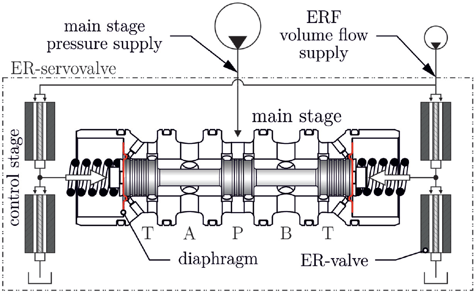
Schematic representation of the ER servo valve.
In the main stage, also called power stage, there is a 4/3 way valve spool mounted between two compression springs. The compression springs provide a defined spool stop position and close the valve in the event of an electric field strength breakdown. Specially molded diaphragms spatially separate the volumes of the two valve stages, such that there is no mixing of the two hydraulic circuits. The diaphragms additionally enable a dynamic deflection of the valve spool with negligible resistance. Figure 2 shows a sectional view of the servo valve graphically.
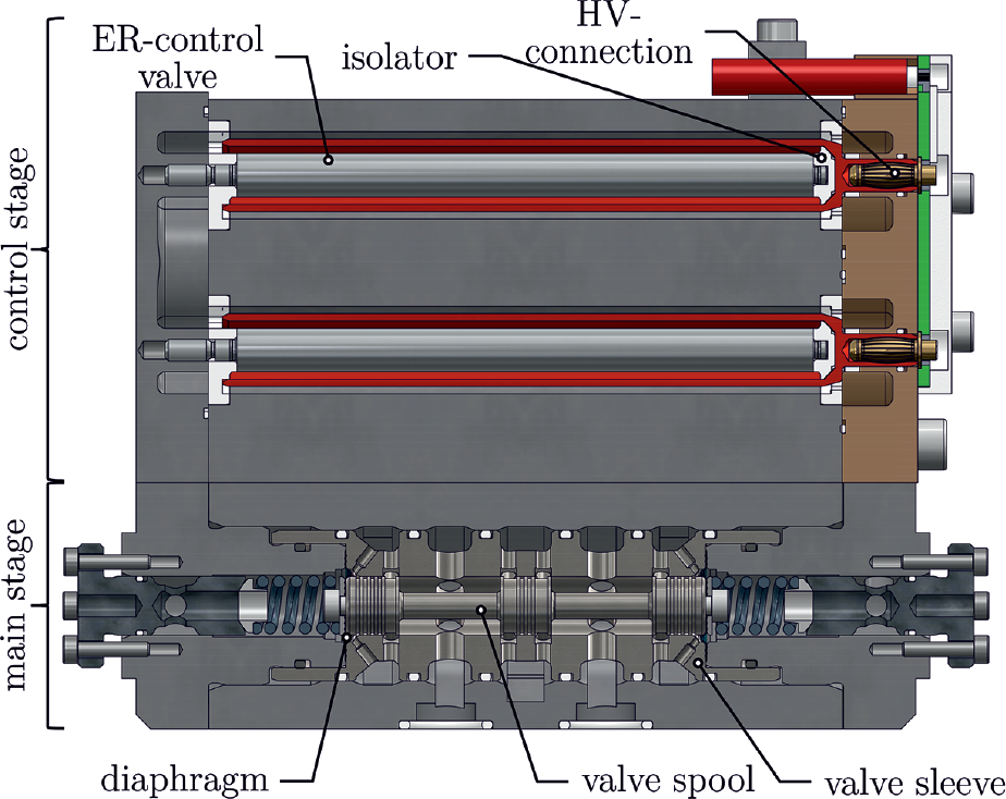
Sectional view of the valve design.
3. Modeling
Figure 3 illustrates the schematic representation of a hydraulic half-bridge in the pilot stage derived from the valve working principle. The aim of this section is to develop the pressure build-up equation in the control chambers of the main stage.

Schematic representation of the hydraulic system in a half-bridge.
The excitation by the switchable pressure due to the ER effect is taken into account by the pressure function


In this case,

Substituting the volume flows into the pressure balance yields the control pressure build-up behavior equation

where

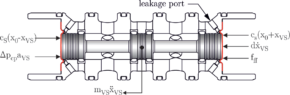
Schematic representation of the mechanical system in the main stage.
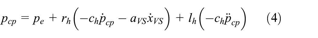
The control pressure acting on the spool end surfaces
4. Performance of the control stage
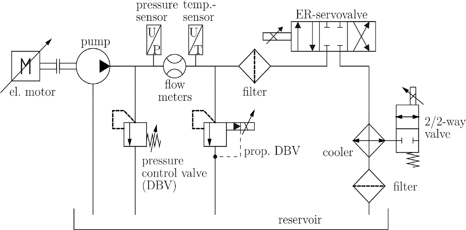
The hydraulic circuit to measure the pilot stage performance is shown in Figure 5. The suspension used is RheOil4.0.
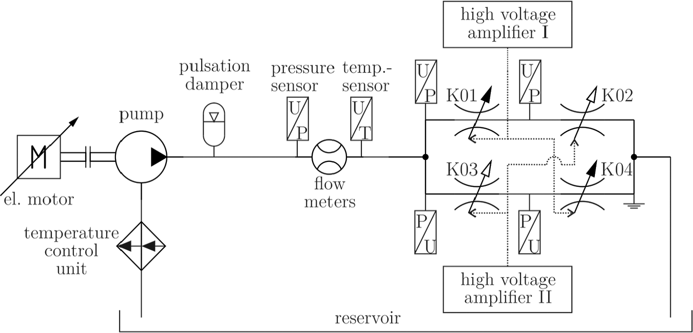
Pilot stage supply system.
In the hydraulic circuit, the volume flow can be controlled and variably adjusted by the combination of an electric servomotor and a constant pump. A pulsation damper ensures an undisturbed volume flow through the ER valve. Both the volume flow and the suspension temperature are measured before entering the pilot stage. Pressure transducers measure the system and the control pressure. A temperature control unit heats the suspension to an operating temperature of 60°C for its fast response (Gurka et al., 2011; Ulrich et al., 2009). Two high-voltage amplifiers adjust the field strength in the electrical active gaps.
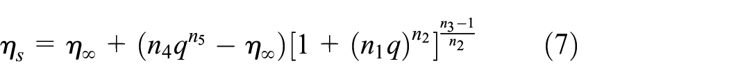
For the investigation of the static and dynamic pilot stage properties, the valve spool is fixed in the main stage at first. Hence, the measured characteristic pressure curve is shown in Figure 6. It describes the pressure drop across a control valve as a function of the volume flow rate and the applied electric field strength. For modeling the field-dependent static rheological behavior of the suspension, the modified Carreau–Yasuda equation by Ulrich et al. (2009) has proved (Heinken et al., 2015; Krivenkov et al., 2013)
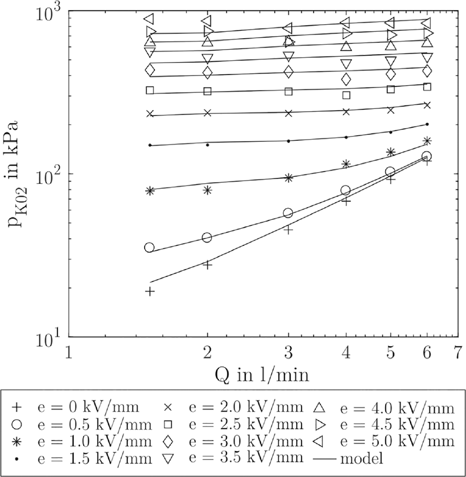
Pressure drop across the ER valve at a volume flow rate of Q = 1.5–7 L/min, an electric field strength of e = 0:0.5:5 kV/mm, and a fluid temperature of
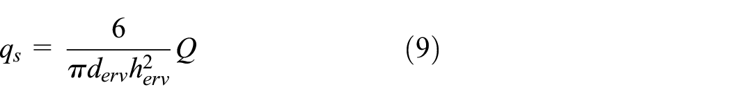
For this, the volume flow must be converted into the geometry-independent scaled shear rate
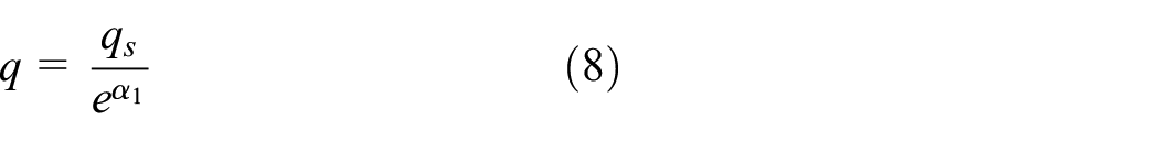
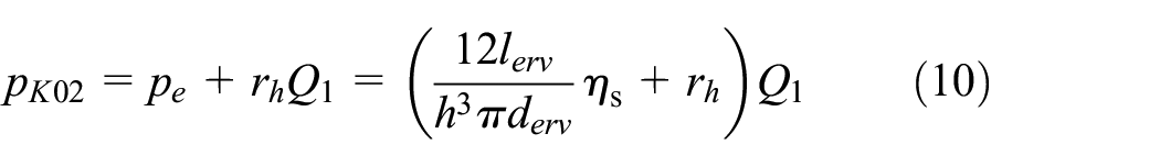
Substituted into the static pressure balance, the equation describes the control pressure of an ER valve as a function of the volume flow and the applied electric field strength
The results of the model are validated by the measurement data in Figure 6. Only at low volume flow rates and high electric field strength it shows a discrepancy between the experiment and the model. All model parameter values are listed in Appendix 1.
The dynamic pressure build-up behavior was determined by the reciprocal control of the half-bridge elements in the pilot stage. The reciprocal control reduces the capacitive volume in the pilot stage and thus decreases the reaction time of the electrohydraulic converter. Figure 7 illustrates the results as frequency responses.
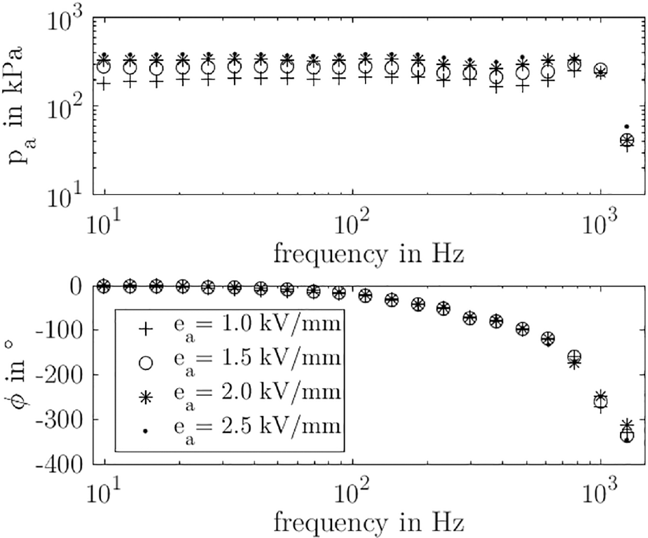
Frequency response of a half-bridge at a volume flow rate of Q = 3.5 L/min, a bias electric field strength of eb = 2.5 kV/mm, an amplitude of ea = 0.5:0.5:2.5 kV/mm, and a fluid temperature of
The frequency responses emphasize the potential of an ER pilot stage. It can be seen that the achievable pressure amplitudes in the half-bridges have a constant high dynamic range up to 1000 Hz. This dynamic is almost independent of excitation magnitude. For the analytical description of the dynamic fluid behavior, many papers considered the dynamic electrical behavior of the respective suspension isolated from the hydraulic system (Clack et al., 1994; Firoozian, 1996; Hosseini-Sianaki et al., 1994; Krivenkov et al., 2013; Whittle et al., 1994). This has the advantage that the dynamic hydraulic parameters like the inertias and resistances have almost no influence on the ER effect dynamic modeling. Hosseini-Sianaki et al. (1994) and Krivenkov et al. (2013) used a phenomenological model that considers the suspension in the ER valve as a conducting dielectric between the electrodes of a capacitor. From the measured frequency-dependent dielectric properties, they derived a dynamic fluid model as a transfer function of the complex resistance
The impedance is the inverse of the complex conductance
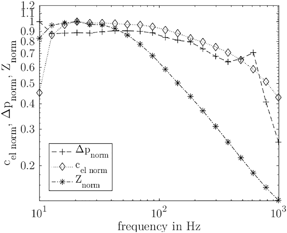
Amplitude response of the normalized pressure, impedance, and capacity.
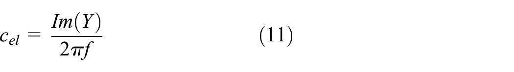
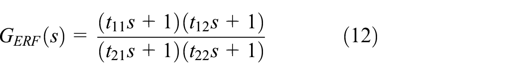
Therefore, the dynamic behavior of the suspension is derived from the time constants of the electrical capacitance with a transfer function
By contrast, the dynamic hydraulic behavior can be taken from the standardized control pressure. It clarifies the natural frequency of the hydraulic, which is explained by the resonance in the upper frequency range. Fixing the valve spool in the main stage eliminates the influence of spool movement in the pressure build-up process, and equation 5 is simplified to a standard hydraulic
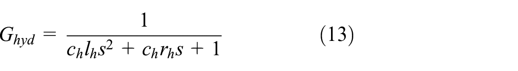
The dynamics of the control pressure can finally be calculated from the series connection of the transfer functions

The results of the simulation model for the pilot stage dynamic behavior are compared with the measured data in Figure 9 as the frequency response and in Figure 10 as a normalized step response in the time domain. They show very good agreement. In particular, the good agreement of the delay time behavior and the phase characteristic is important for a closed-loop controller development later on.
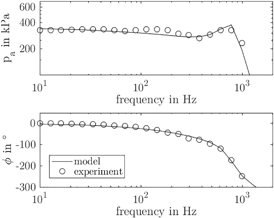
Comparison of the frequency responses between the simulation model (equation (14)) and the experiment at Q = 3.5 L/min, eb = 2.5 kV/mm, ea = 2.0 kV/mm, and
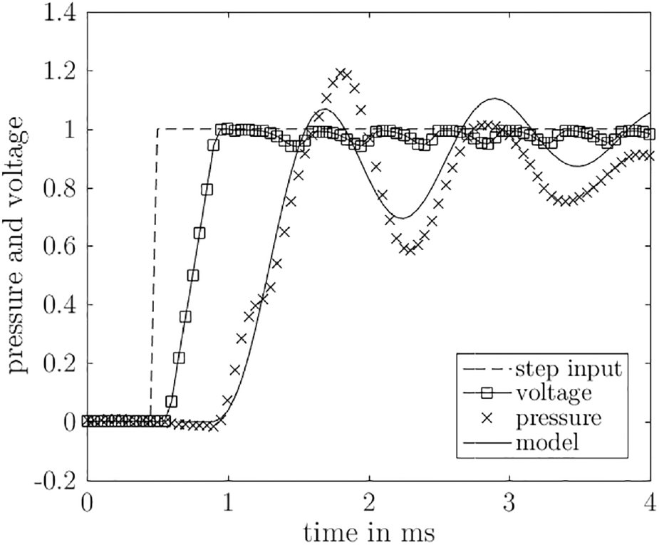
Comparison of the step responses between the simulation model (equation (14)) and the experiment at Q = 3.5 L/min, e = 5 kV/mm, and
5. Performance of the second stage
After modeling the electrohydraulic drive in the pilot stage, the following section introduces the modeling of the valve main stage. For the model development and validation, measurement results of the main stage performance tests in a test rig with conventional hydraulic oil (HLP 46) are used (see Figure 11).
Hydraulic supply system for the valve main stage.
In order to determine the pressure-dependent volume flow stroke characteristic and the effective flow force, a test setup with a mechanical spool adjustment unit was used. It is illustrated schematically in Figure 12. The valve spool is mechanically connected to a displacement and force sensor, whereby the manually set spool position and the flow force acting on the spool can be measured. Pressure transducers at the main stage connection ports detect the pressure drop across the metering edges. The flow forces thus recorded at different system pressures
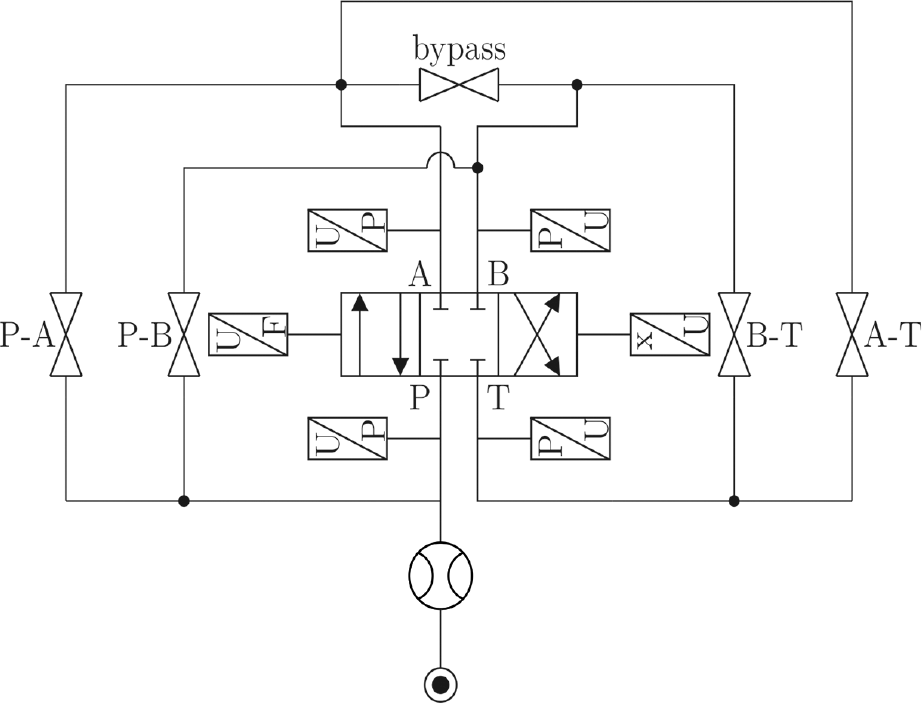
Main stage test rig.
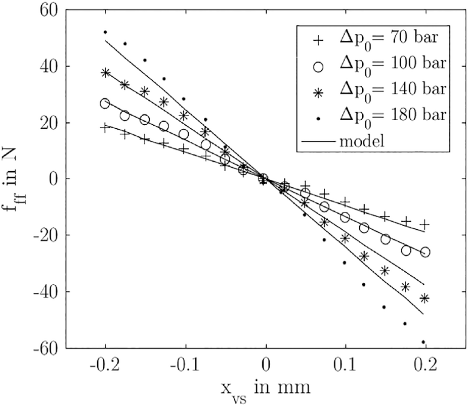
The measured flow forces compared to the model (equation (15)) as a function of the spool stroke at different system pressures and an oil temperature of 60°C.
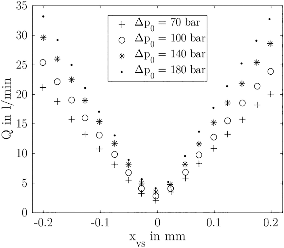
Characteristic valve flow curve as a function of the spool stroke at different system pressures and an oil temperature of 60°C.
As already mentioned, the stationary part of the acting flow force can be described as a path-dependent and pressure-dependent variable with the stiffness


The adjusted volume flow at the metering edge can be calculated using the orifice flow equation as a function of the spool stroke
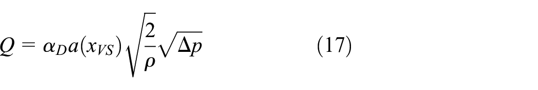
The dimensionless orifice flow coefficient
ρ is the density of the HLP 46. In order to represent the valve volume flow output as a function of the control pressure, the static equilibrium force on the spool has to be resolved according to the stroke
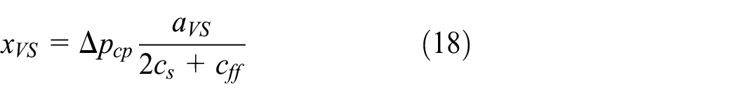
The obtained dependence between the spool stroke and the control pressure can be substituted into the orifice equation and thus results in the valve output as a function of the control pressure (see Figure 15)
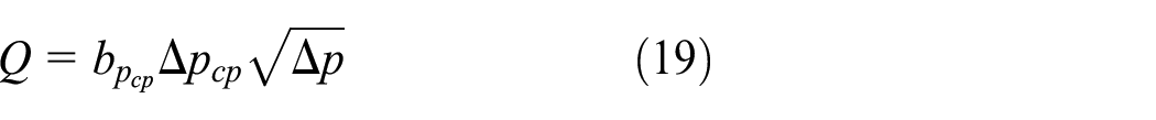
The valve output volume flow as a function of the control pressure compared to the model results (equation (19)).
Using the established relationship between the electric field strength in the ER valves of the pilot stage and the acting pressure on the valve spool (equations (5) and (6)), the main stage output can also be explained as a function of electric field strength (see Figure 16).
The valve output as a function of the electric field strength compared the model results (equation (17)).
6. Dynamic behavior of the ER servo valve
The dynamics of the overall system was initially tested without hydraulic consumers with depressurized main stage. Figure 17 illustrates the measured frequency responses of the control pressures in the two half-bridges reaching a constant dynamic up to 233 Hz. It makes clear that the valve spool cannot follow the control pressure signal over the entire dynamic bandwidth. In order to determine the reason for this dynamic reduction, the influence of individual components such as the diaphragm, the springs, and the spool-sleeve assembly in the main stage was isolated and analyzed. It could be determined that mainly friction and clamping effects due to manufacturing inaccuracies of the spool-sleeve assembly affect the dynamic behavior of the servo valve adversely.
The frequency response of the control pressure in the half-bridges at Q = 3.5 L/min through each half-bridge,
Since the spool stroke is not measured explicitly, only the implicit impact of the spool behavior in the pressure signal can be considered. The only feedback between the control stage and the main stage exists as the volume flow consumption of the valve spool (see Figure 18).
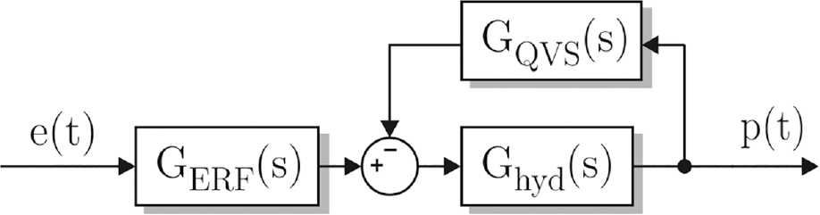
Simplified representation of the feedback in the system.
If this volume flow increases at resonance frequency in the power stage over a critical limit, the control pressure breaks down due to the volume flow fluctuation in the electrical active gaps on the pressure-switching side. At the same time, the volume displaced by the spool has to be pressed through the control valve on the opposite side, which results in further pressure fluctuations amplification.
If the impact of the valve spool on the half-bridges as a function of its flow consumption is extended by a second-order transfer function
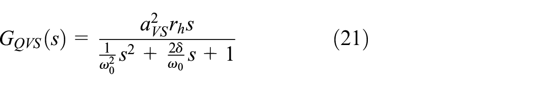
with
The present model is thus able to describe the complete static and dynamic valve behavior. Figure 19 illustrates how the ER servo valve behaves if the main stage is pressurized. This figure demonstrates the frequency responses of the pressure feedback–controlled pilot stage. At this test, the pressure in the main stage was set to 180 bar and the valve connected to a linear actuator.
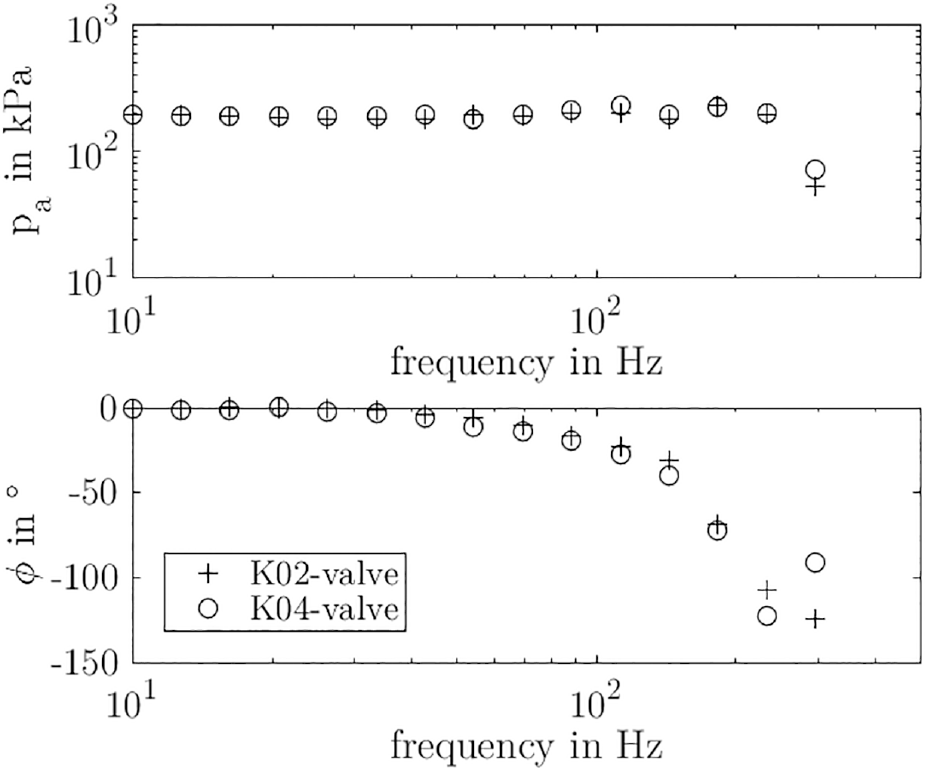
The frequency response of the controlled pressure in the half-bridges.
It figures out that the servo valve works very well under load condition and reaches a dynamic over 233 Hz. In addition, the amplitudes of the control pressures are identical and indicate a very symmetrical control of the valve spool by the half-bridges.
7. Conclusion
To extend the performance of hydraulic actuators, a servo valve with an ER drive was developed. It consists of four ER valves in the pilot stage and a 4/3-way valve spool in the main stage. Diaphragms separate the two stages. The developed ER servo valve convinces with a flow rate of 18 L/min at 180 bar and a high dynamic range over 233 Hz. Compared to other pilot stages, the developed electrohydraulic converter provides constant control pressure with high dynamic up to 1000 Hz regardless of the input signal’s magnitude. The ER servo valve thus increases the performance of hydraulic drives and is able to combine the high power density of conventional hydraulic linear drives with the high dynamics of ER systems. To be able to describe the static and dynamic behavior analytically, a valve simulation model was developed in this work. For this, the characteristic equations were listed. In particular, a model for describing the dynamic behavior of the used ER fluid RheOil4.0 was presented. The simulation results agree well with the tested system behavior. The developed simulation model is thus suitable to develop various valve feedback controllers or to design further ER-driven servo valves of different nominal sizes.
Footnotes
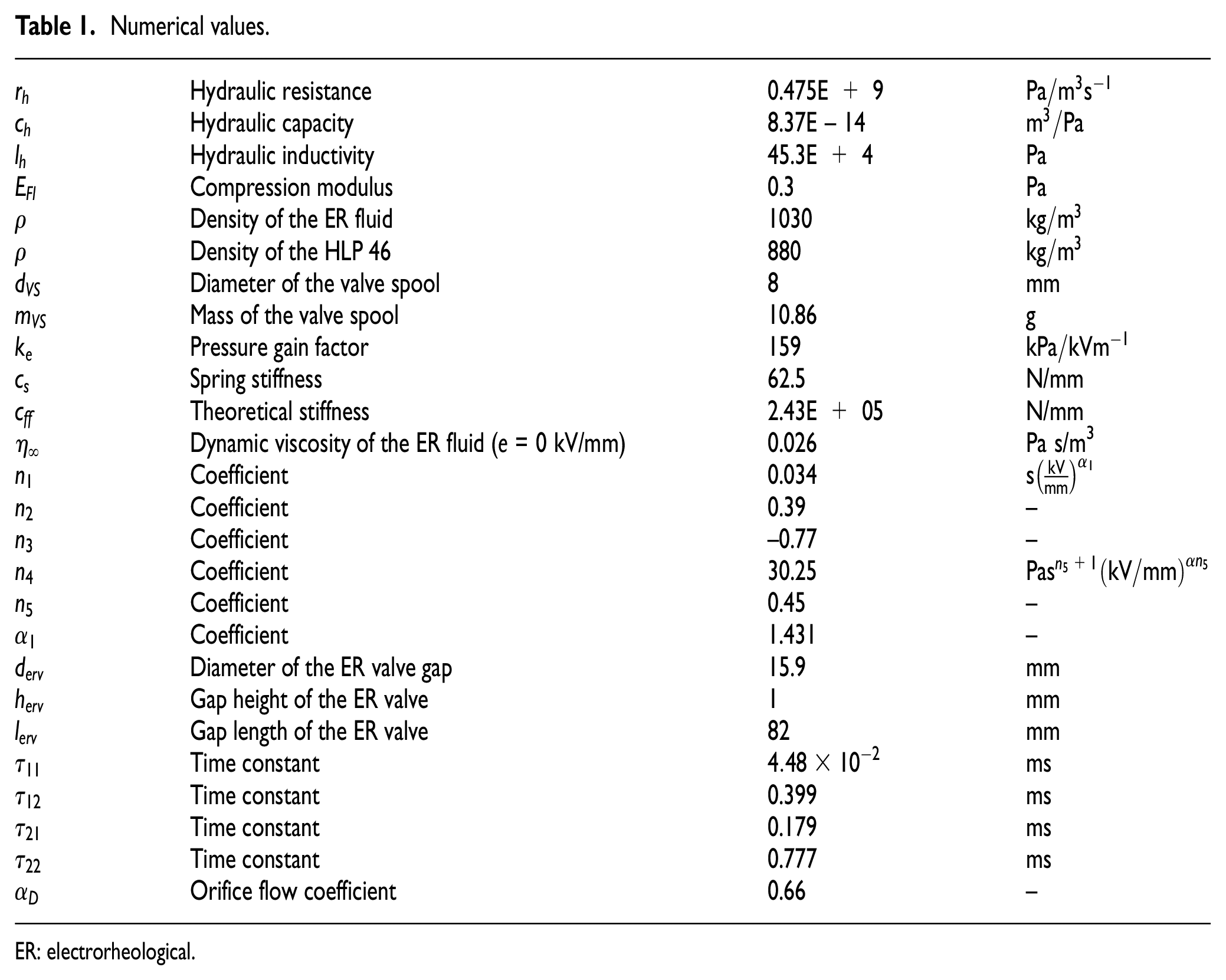
Appendix 1
Numerical values.
| Hydraulic resistance | 0.475E + 9 | ||
| Hydraulic capacity | 8.37E – 14 | ||
| Hydraulic inductivity | 45.3E + 4 | ||
| Compression modulus | 0.3 | ||
| Density of the ER fluid | 1030 | ||
| Density of the HLP 46 | 880 | ||
| Diameter of the valve spool | 8 | mm | |
| Mass of the valve spool | 10.86 | g | |
| Pressure gain factor | 159 | ||
| Spring stiffness | 62.5 | N/mm | |
| Theoretical stiffness | 2.43E + 05 | N/mm | |
| Dynamic viscosity of the ER fluid (e = 0 kV/mm) | 0.026 | Pa s/m3 | |
| Coefficient | 0.034 | ||
| Coefficient | 0.39 | – | |
| Coefficient | −0.77 | – | |
| Coefficient | 30.25 | ||
| Coefficient | 0.45 | – | |
| Coefficient | 1.431 | – | |
| Diameter of the ER valve gap | 15.9 | mm | |
| Gap height of the ER valve | 1 | mm | |
| Gap length of the ER valve | 82 | mm | |
| Time constant | ms | ||
| Time constant | 0.399 | ms | |
| Time constant | 0.179 | ms | |
| Time constant | 0.777 | ms | |
| Orifice flow coefficient | 0.66 | – |
ER: electrorheological.
Declaration of conflicting interests
The author(s) declared no potential conflicts of interest with respect to the research, authorship, and/or publication of this article.
Funding
The author(s) disclosed receipt of the following financial support for the research, authorship, and/or publication of this article: The research is supported by the Bundeswehr Technical Center for Ships and Naval Weapons in Eckernförde, Germany.