
Abstract
The dielectric elastomer generator is a stretchable generator that converts low-frequency motions into electrical output, with excellent impedance matching capabilities. However, the dielectric elastomer requires an external high-voltage priming source to initialize its operation. We previously proposed a piezoelectric generator as the priming source, and demonstrated a net amplification of specific output energy of 1.8 times by the dielectric elastomer generator, as compared with that of the piezoelectric working in isolation. We termed our prototype the dielectric-elastomer-amplified piezoelectric (DEAmP). In this version, we introduce a self-priming circuit that will progressively charge up the dielectric elastomer generator to a much higher potential, thereby allowing the system to approach its optimized operating voltage. We term this the DEAmPx generator, with the letter “x” denoting progressive voltage/charge amplification by the self-priming circuit. The DEAmPx attained an output voltage of about 2000 V in 18 cycles and generates a dielectric elastomer generator–specific energy output of 3.1 mJ/g per cycle—19 times higher than that of the piezoelectric generator working in isolation. The system-specific energy output of DEAmPx is 0.49 mJ/g, with just a single layer of elastomer film. With this significantly larger output, we demonstrate the capability of a single-layer DEAmPx to power dielectric elastomer actuators.
1. Introduction
Low-power sensors and actuators could be autonomously powered by harvesting energy from ambient motion sources. Traditional motion–based energy harvesters use electromagnetic or piezoelectric generators to harvest ambient motions and convert them into electrical outputs. All of them, however, require ambient motions to be regular and fast in speed, in order for usable power to be harvested. The dielectric elastomer generator (DEG) is an emerging technology that is capable of harvesting low-frequency and low-speed ambient motion like sea waves (Kornbluh et al., 2011; Moretti et al., 2018) and human footfall (Kornbluh et al., 2002; Paradiso and Starner, 2005). Dielectric elastomers (DEs) are stretchable capacitors that consist of an elastomeric membrane sandwiched by compliant electrodes. When a low-voltage (Φ) charge is placed on a stretched elastomer prior to contraction, the contraction work against the Maxwell pressure increases the potential of the charge (Φ′, where Φ′ > Φ), thus generating a surplus amount of energy (Figure 1) (Kornbluh et al., 2002; Pelrine et al., 2001). The most common elastomers used for DEGs are acrylics (Huang et al., 2013; Koh et al., 2011a; McKay et al., 2010b; Pelrine et al., 1997; Shian et al., 2014), silicones (Madsen et al., 2016; Skov and Yu, 2017), and natural rubber (Kaltseis et al., 2014; Koh et al., 2011a). The most commonly used electrodes are carbon-based and are classified into three categories, carbon powder, carbon grease, and conductive rubber (Rosset and Shea, 2013). High specific energies of up to 0.78 J/g (Shian et al., 2014), at least 10 times that of existing technologies like piezoelectric and electromagnetic systems, have been reported for DEGs (Kornbluh et al., 2002, 2012). DEGs offer many advantages over conventional generators. They are low cost, light weight, operates noise-free, resists corrosion, and present good impedance matching to many low-frequency ambient sources (Kornbluh et al., 2002; Pelrine et al., 2001; Suo, 2010). However, DEGs require an external high-voltage source to initialize energy conversion.
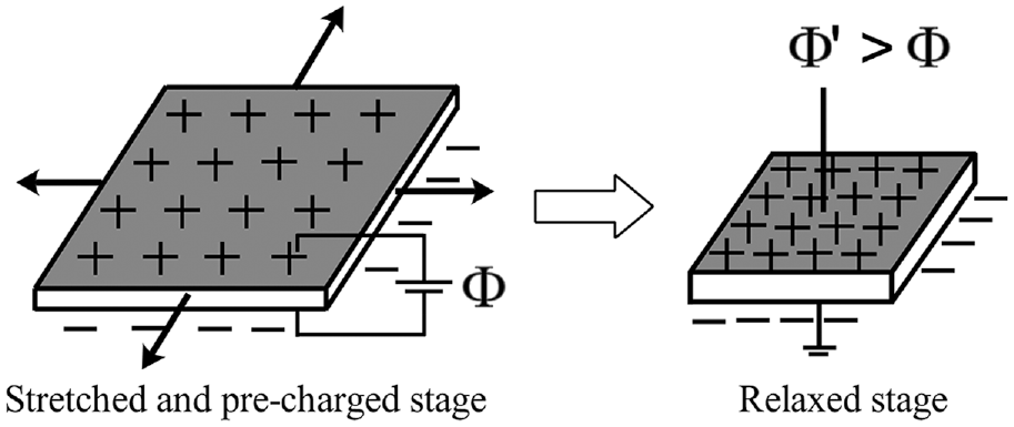
Working principle of the dielectric elastomer generator (DEG). The DE membrane is stretched mechanically and pre-charged with Φ. When the DE membrane is relaxed, the work done by the membrane against the Maxwell pressure, hence increasing the voltage of the charge to Φ′ (Φ′ > Φ).
Currently, there are two approaches to free the DEG from an external high-voltage electrical source: one, by coupling it with another motion-based energy harvester or two, to use an initial charge source with a self-priming circuit (SPC) that enables the DEG to prime itself so as to progressively amplify its voltage on each cycle (Ikegame et al., 2017; Illenberger et al., 2017; 2018; McKay et al., 2010a, 2010b, 2012; Mathew and Koh, 2018; Zanini et al., 2016). Electrets (Jean-Mistral et al., 2012, 2014; Lagomarsini et al., 2017; Vu-Cong et al., 2013a, 2013b) and piezoelectric generators (Alexandru et al., 2016; Clara et al., 2018; Mathew et al., 2019) are considered for the first approach. However, as electrical energy input scales with the square of the electric field (
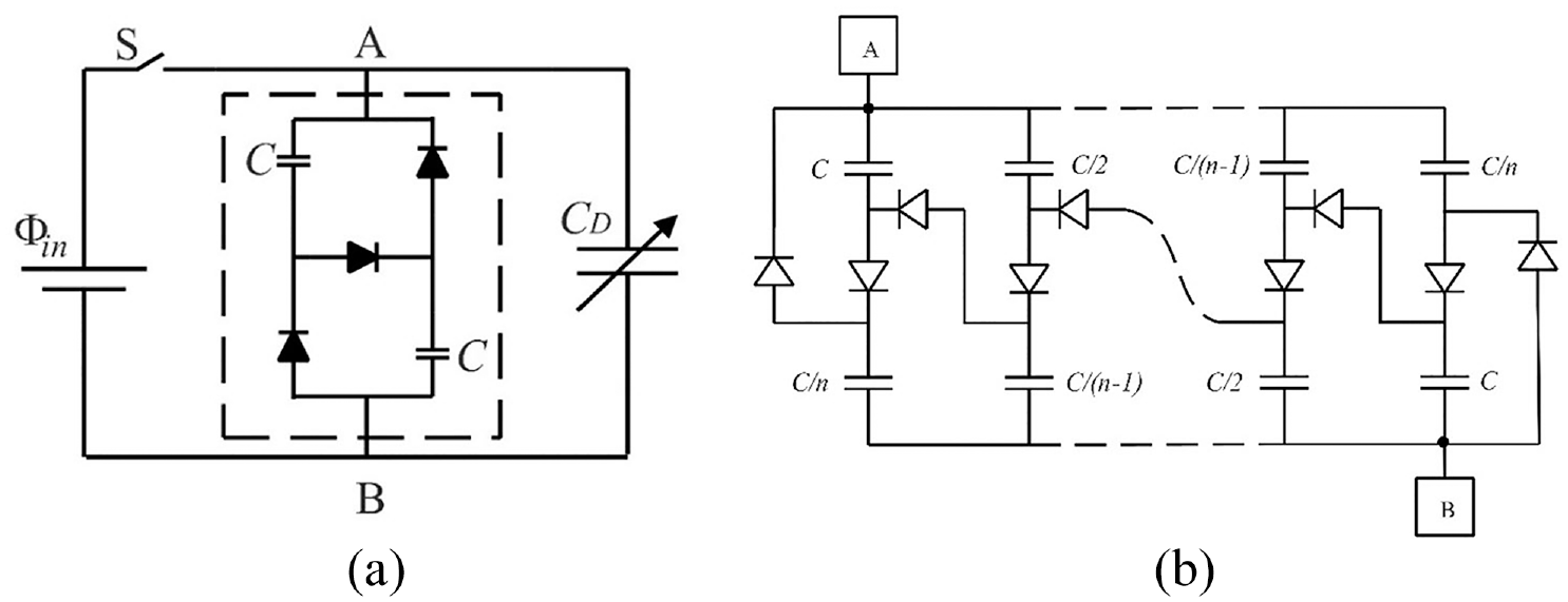
(a) Basic circuit of a self-primed dielectric elastomer generator (SP-DEG). A first-order self-priming circuit is inscribed in a dashed rectangle. When charge flows from point A to B, the SPC capacitors assume a series configuration (high-voltage form) and when the charge flows from point B to A, the SPC capacitors assume a parallel configuration (high-charge form). DEG is represented as a variable capacitor (CD). Switch “S” is kept ON for the initial priming of SP-DEG via a low-voltage source Φ in . (b) nth-order SPC.
Anderson et al. used the SPC with microbial fuel cells (MFCs) or solar cell arrays as the charge source (Anderson et al., 2010, 2011; McKay et al., 2012). The physical process of energy conversion of MFCs or solar cell arrays is dissimilar to DEGs. Hence, they cannot be easily integrated to produce small-scale motion-based energy harvesters. Illenberger et al. (2018) used an electret as a charge source for the SP-DEG instead. Electrets are readily available but are expensive to purchase or produce. They require periodic priming from plasma discharge as its charges will eventually be depleted. In this work, we use a commonly available lead–zirconate–titanate (PZT) piezoelectric diaphragm as the initial charge source for the SP-DEG system. We term this the DEAmPx generator, where DEAmP refers to dielectric-elastomer-amplified piezoelectric (DEG coupled with a piezoelectric generator), previously proposed by the authors (Mathew et al., 2019), and the letter “x” denotes the progressive voltage amplification by the SPC.
Connecting the DEAmPx to an electrical load or a storage unit allows it to transfer a part of its internal energy to do useful work or to store the output charges. With the objective of quantifying this energy output, we analyzed a DEAmPx connected to an output capacitor. Our analysis suggests that the voltage boost per cycle of the system increases with the DEG capacitance ratio. For a space-constrained design, a DE deformation mode, namely, the ripple mode was introduced (Mathew et al., 2019) to induce a large capacitance ratio for the DEG (Figure 3). Based on our analysis, we present a fully autonomous generator prototype that integrates these three components: an SPC that is electrically connected with the DEG, the DEG deformed in ripple mode, and a PZT diaphragm as a charge source. Our compact design makes it suitable to be used as a small-scale energy harvester where the ambient motion source is of a compressive nature, like that of a human heel strike during walking. Experiments are carried out to characterize the energy harvesting capability of the prototype connected to a constant voltage output reservoir, which is a special case of a biased output capacitor where the output capacitance tends to infinity. Finally, we demonstrate the capability of our prototype to power two types of DE actuators (which essentially are output capacitors), which was previously suggested, but not demonstrated, by Anderson et al. (2012). Our demonstration allows safe and untethered operation of the DE actuator (DEA) that requires very large voltage to operate.
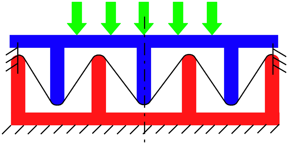
Cross-sectional view of the ripple mode of deformation for DEG. The top and bottom rigid structures (blue and red) deform the DE film (black) out of plane resulting in a ripple shape.
2. State and process modeling of DEAmPx
The electrical voltage source with switch “S” shown in Figure 2(a) is replaced with a rectified piezoelectric (Figure 4). An output capacitor
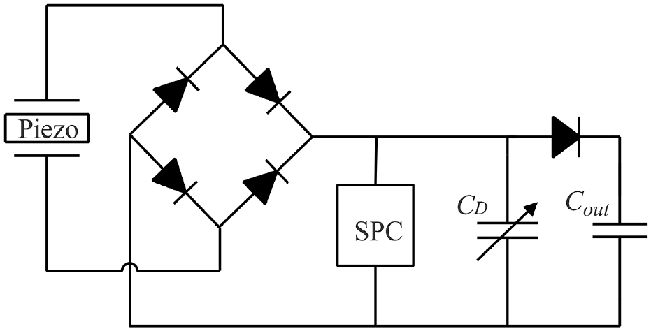
Circuit diagram of DEAmPx connected to an output capacitor via a diode.
For the analytical model, we assume an ideal electrical circuit with zero resistance. We further assume no losses in the diodes and rigid capacitors, and that the DEG consists of electrodes that are perfect conductors and a dielectric that is a perfect insulator. Hence, energy losses within the electrical circuit and its components, and the dissipative processes in the DE such as leakage current and viscoelasticity (Chiang Foo et al., 2012a, 2012b; Zhao et al., 2011) are ignored for the analysis. The operation of the DEAmPx is as follows: the DEG is stretched from a state of minimum capacitance
2.1. Analytical modeling of SP-DEG with an output capacitor
The SP-DEG cycle commences when
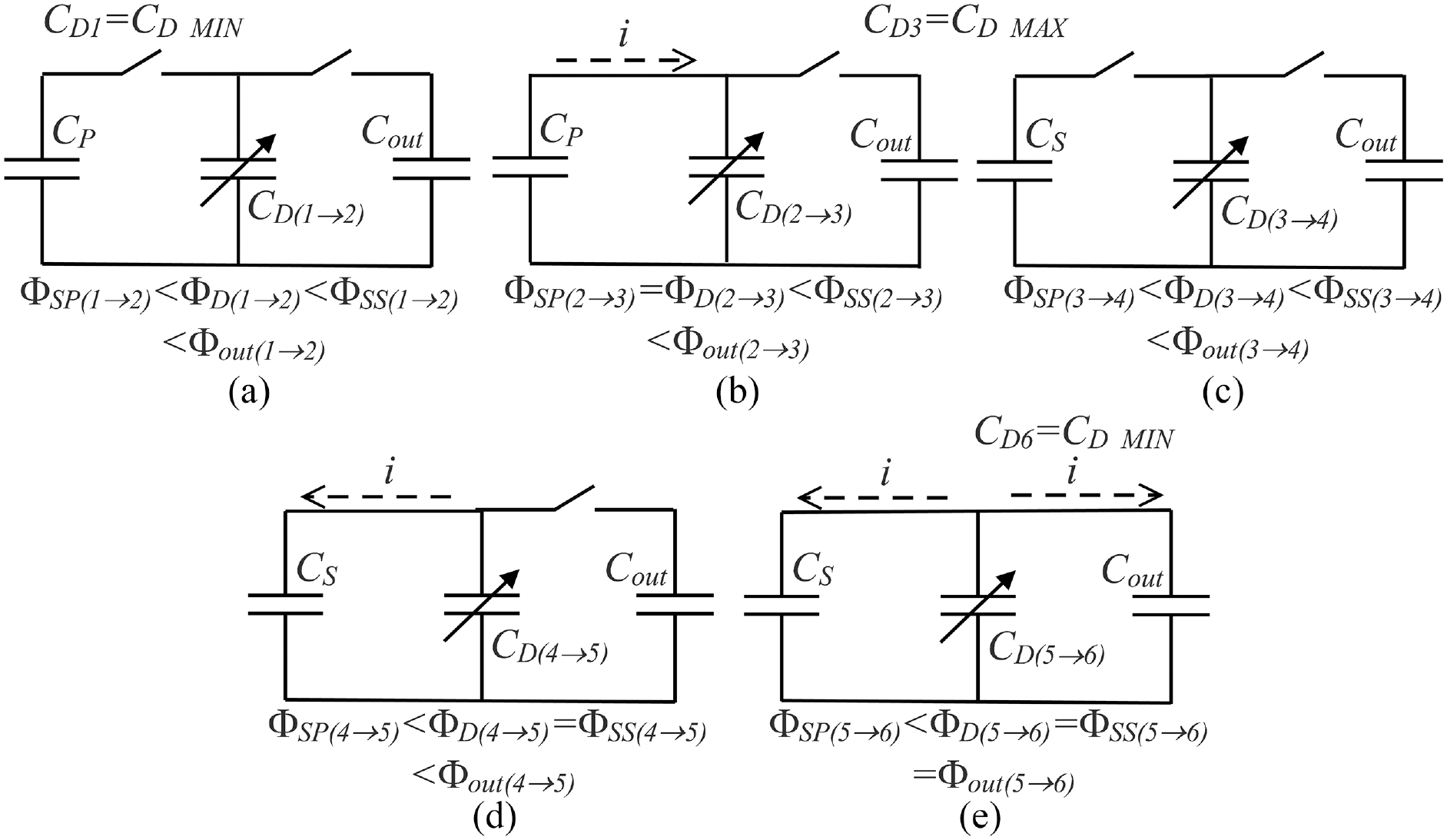
Current flow paths as DEG undergoes one cycle of deformation. (a) Process 1 → 2: DEG stretched from CD_MIN, Φ D > Φ SP , no current flow (open-circuit). (b) Process 2 → 3: DEG is further stretched so that Φ D = Φ SP , charge flows from SPC to DEG until DEG attains CD_MAX. (c) Process 3 → 4: DEG is relaxed from CD_MAX, Φ D < Φ SS , no current flow (open-circuit). (d) Process 4 → 5: DEG is further relaxed so that Φ D = Φ SS , charge flows from DEG to SPC. (e) Process 5 → 6: DEG is further relaxed so that Φ D = Φ SS = Φ out , charge flows from DEG to SPC and output capacitor, until DEG attains CD_MIN.
We develop the equations-of-state for the circuit as follows:
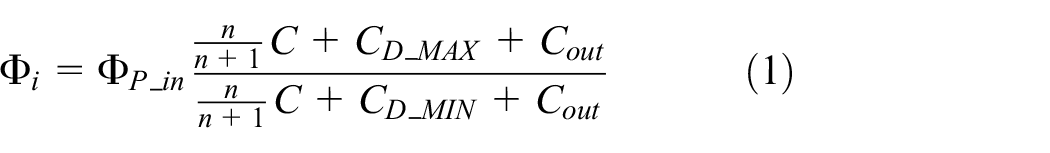
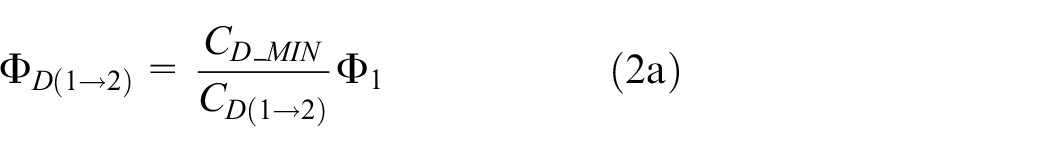
For the process 1 → 2, the DEG is stretched from

While the voltage of the SPC in parallel configuration, is given as
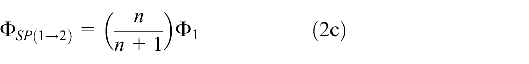
Comparing (2a) and (2c), as long as
where the pre-factor
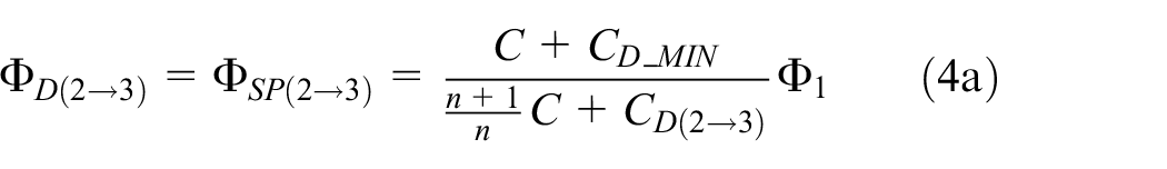

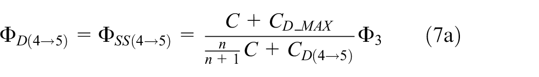
At state 3, the DEG is maximally stretched with its capacitance at
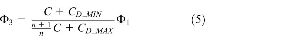
For the process 3 → 4, DEG is relaxed and its capacitance reduces in an open-circuit condition, leading to a voltage increase in the DEG. We have


While the voltage of the SPC in series configuration is given as
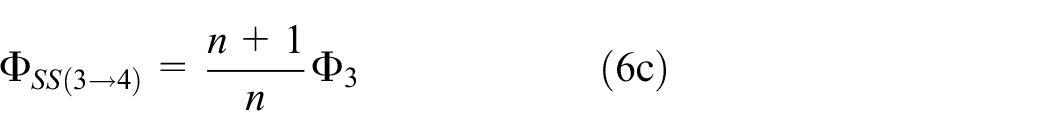
At state 4,

At state 5, the voltage of DEG becomes
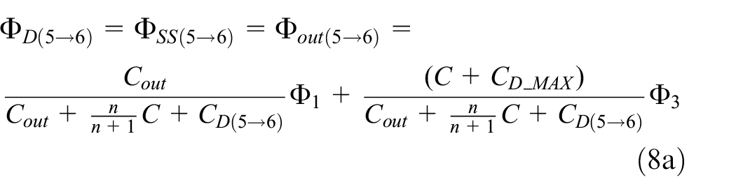

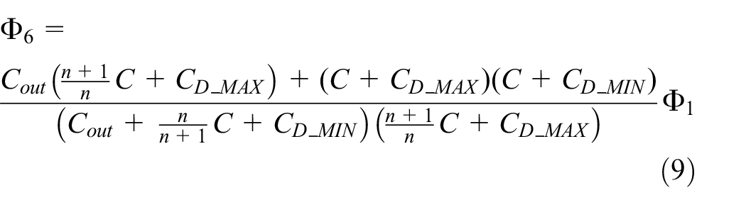
At state 6, the capacitance of the DEG becomes
The cycle restarts with the value of
Energy transferred from SP-DEG system to the output capacitor is given by
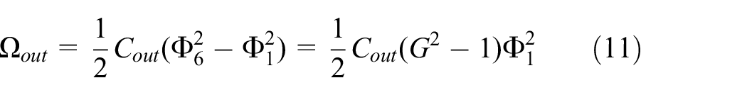
We shall now consider two limiting cases of
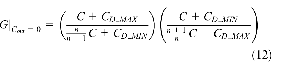
Equation (12) recovers the same equations derived in existing works (Illenberger et al., 2017; Zanini et al., 2016). For the case of
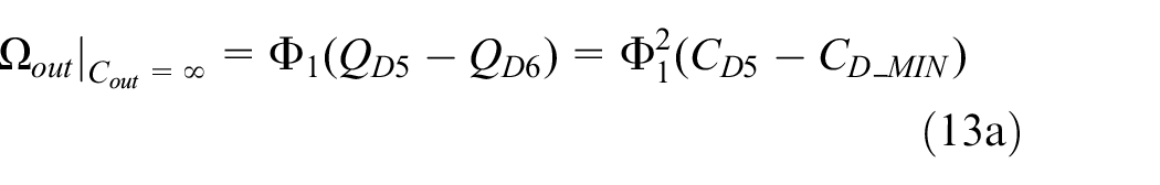
where
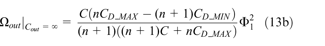
Table 1 provides the summary of the equation of states.
Summary of the equation of states.
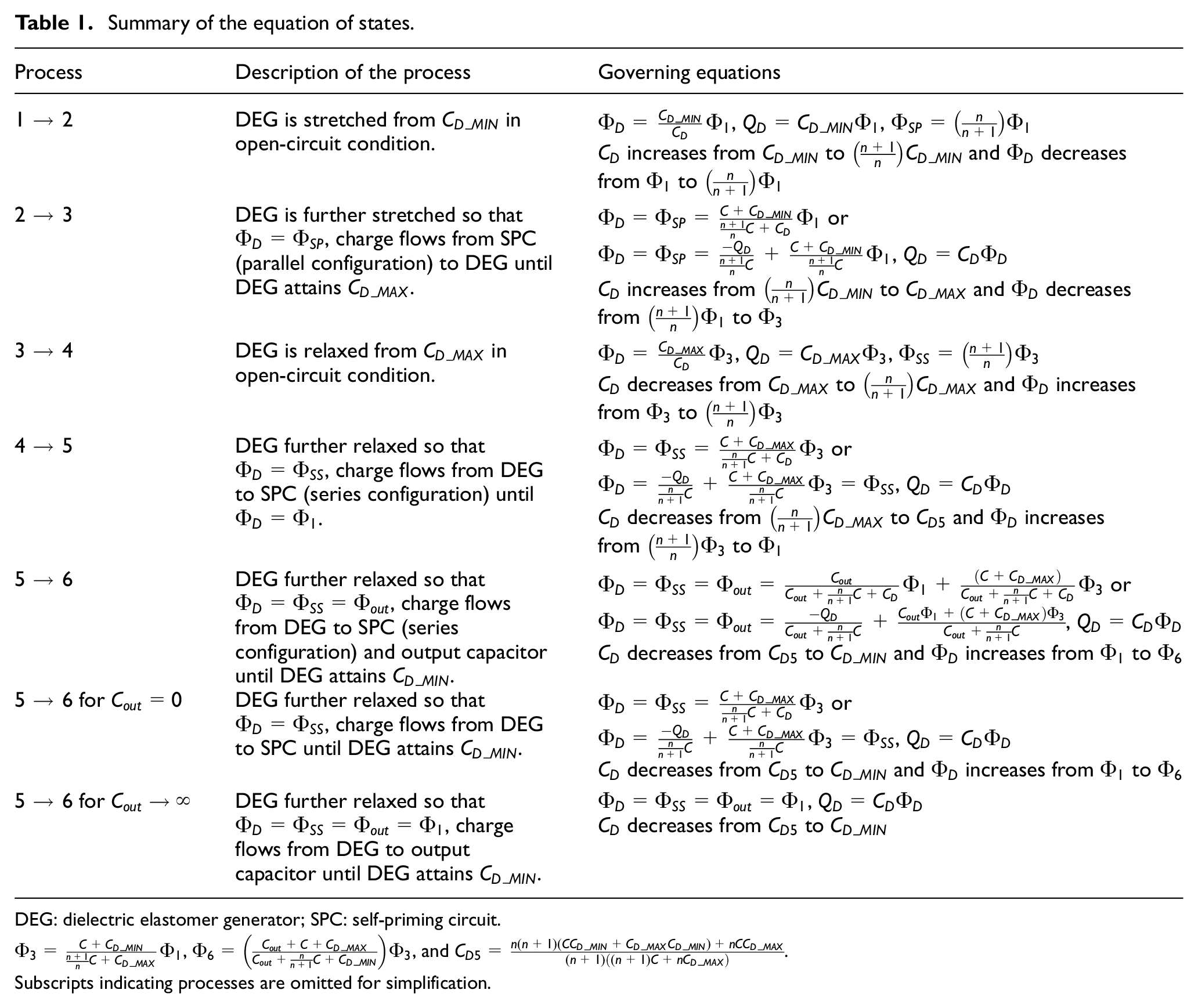
DEG: dielectric elastomer generator; SPC: self-priming circuit.
Subscripts indicating processes are omitted for simplification.
2.2. Graphical illustrations for state processes of SP-DEG
To illustrate operation states and processes of the DEAmPx, we consider an arbitrary example, with operating parameters as follows:
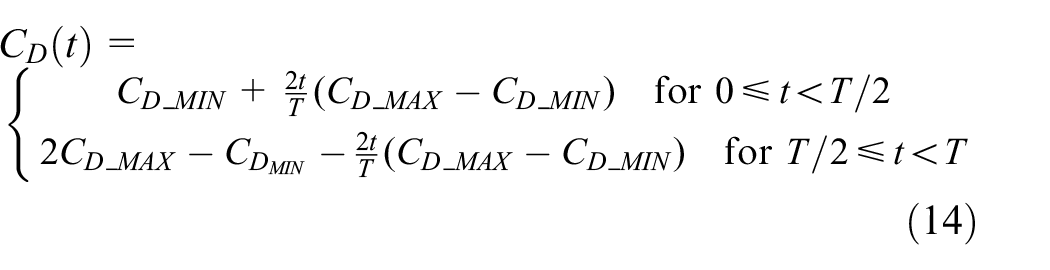
where t is the time and T is the time period for one stretch cycle of DEG.
Figure 6 shows the capacitance change for the DEG (Figure 6(a)) and the corresponding voltage on the DEG, SPC, and the output capacitor (Figure 6(b)) over one period of an SP-DEG cycle. Figure 7 shows the states of the DEG and the SPC plotted on a non-dimensionalized voltage–charge plane. We plot the processes of our example described above, against references of extreme output capacitances of
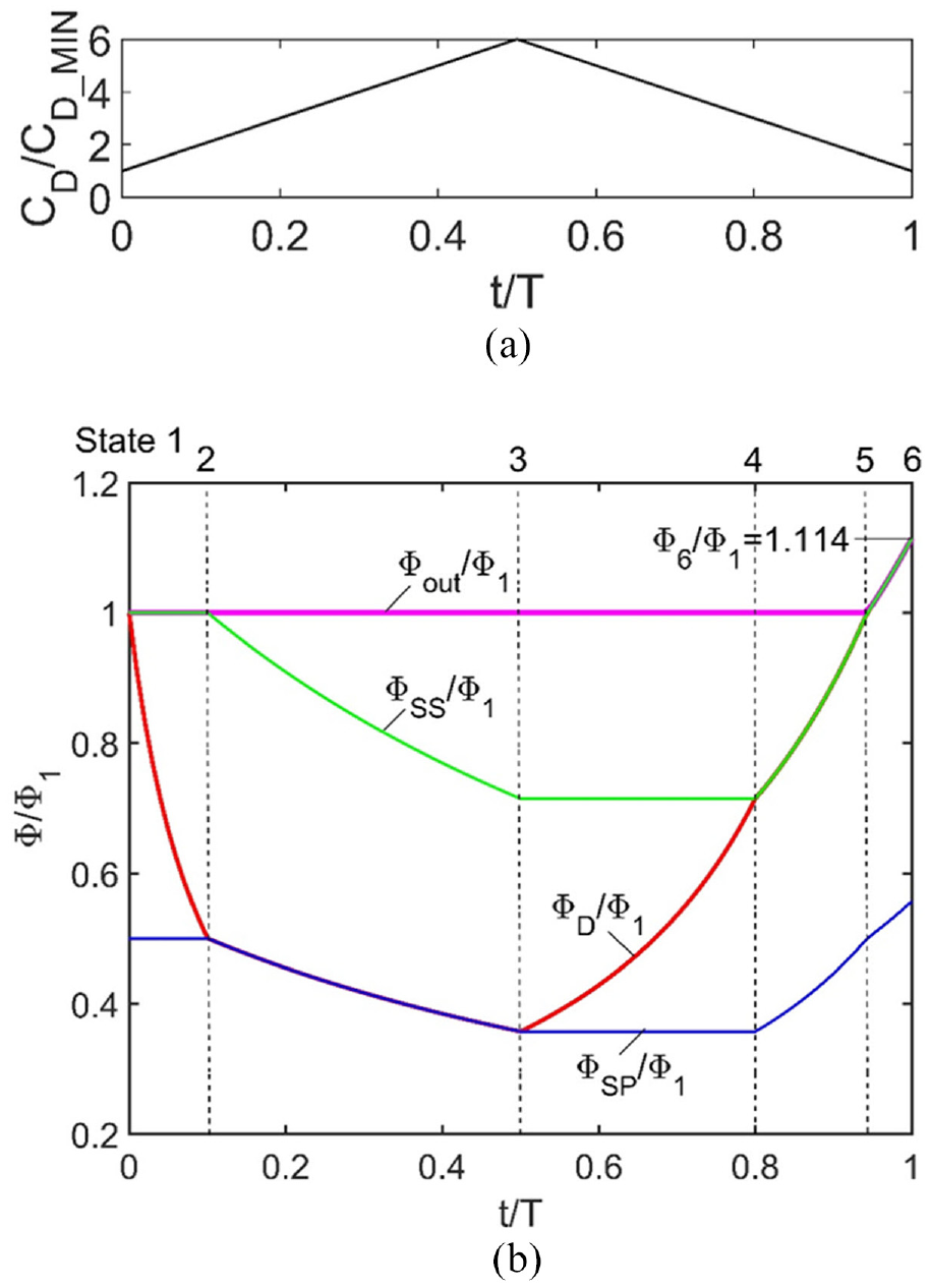
(a) Capacitance change for the DEG versus time and (b) corresponding voltage on DEG (red line), SPC series configuration (green line), SPC parallel configuration (blue line), and output capacitor (magenta line). States of the system are separated by black dashed lines. CD_MAX/CD_MIN = 6, C/CD_MIN = 4, Cout/CD_MIN = 2.
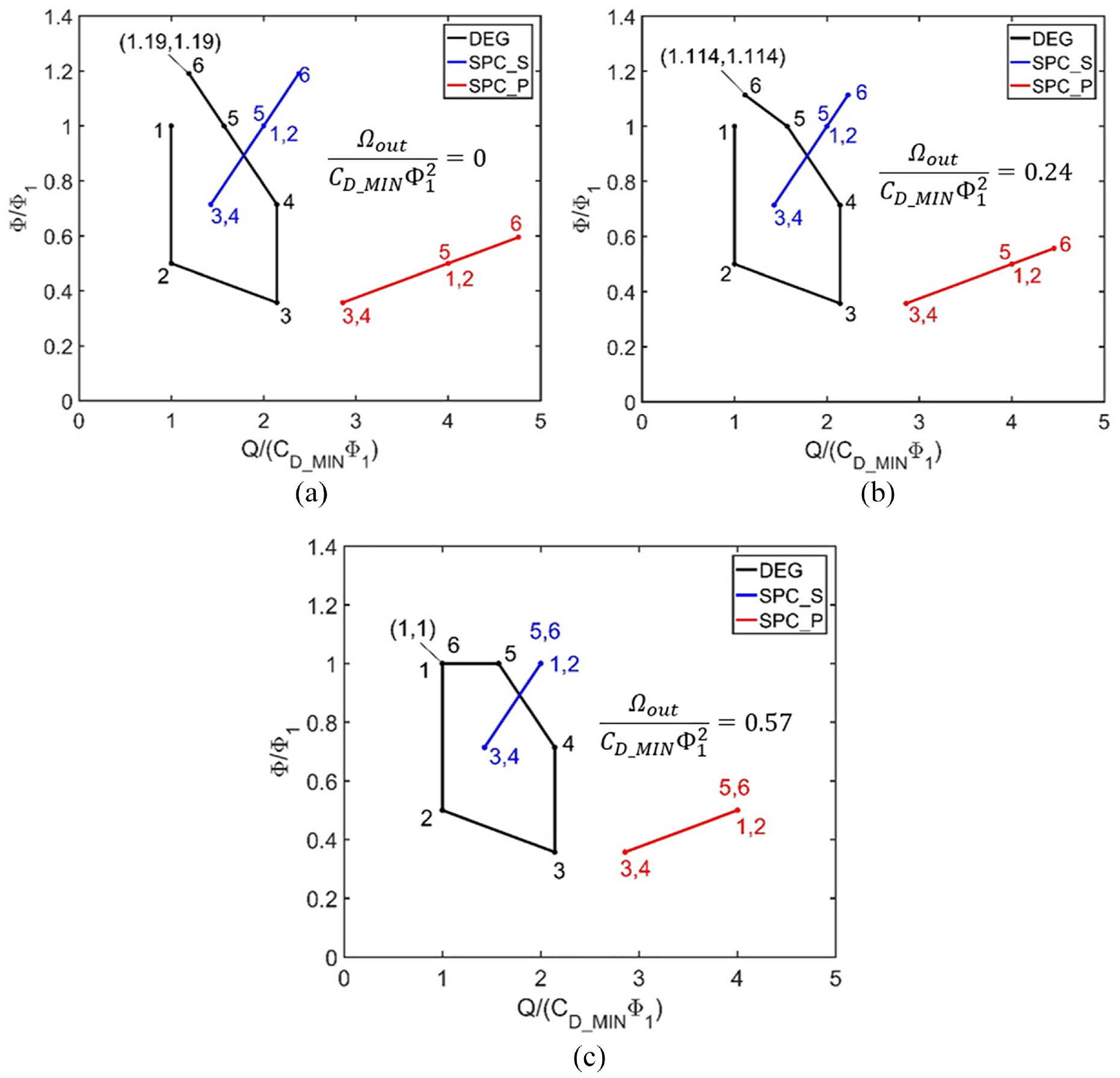
SP-DEG cycle (CD_MAX/CD_MIN = 6, C/CD_MIN = 4, and n = 1) in the voltage charge plane for different cases of output capacitor: (a) Cout = 0, (b) Cout/CD_MIN = 2, and (c) Cout → ∞. The area below the line 2 → 3 represents the non-dimensionalized energy transferred from SPC to DEG, the area below 4 → 5 is the energy transferred from the DEG to SPC, and the area below 5 → 6 represents the energy from the DEG to SPC and the output capacitor. For the case with no output capacitor, energy is transferred from DEG to SPC alone, and when Cout → ∞, all the energy represented by the area under 5 → 6 are transferred to the output capacitor. From geometry, this is equivalent to the area enclosed by the pentagonal cycle (1-2-3-4-5-1). The coordinates of state 6 are mathematically represented by equation (10). Energy transferred to the output capacitor (Ω out ) for each case is shown on the plots.
2.3. Optimal voltage boost
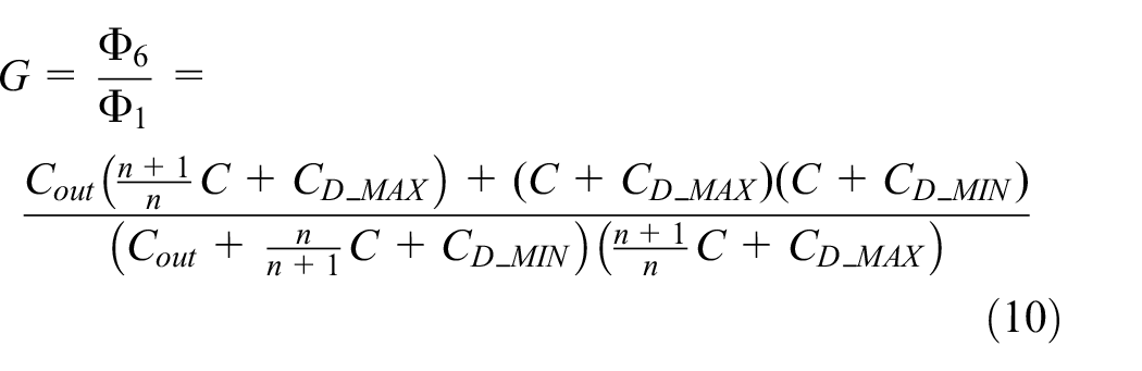
From equation (10), it is easy to see that

where
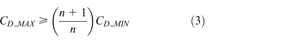
The minimum SPC order is determined by the inequality given in equation (3). When
Using equations (10), (15), and the optimal SPC order, the optimal voltage boost per cycle
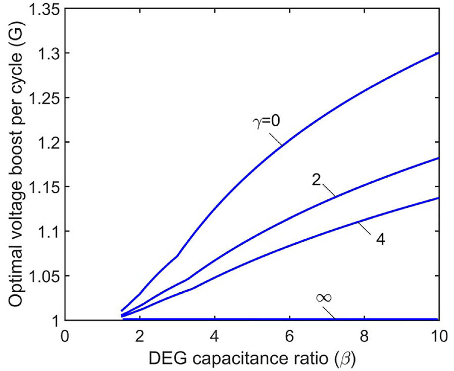
Optimal voltage boost per cycle versus DEG capacitance ratio (β) for different output capacitance ratios (γ). β = CD_MAX/CD_MIN and γ = Cout/CD_MIN.
3. DEAmPx prototype
A prototype as shown in Figure 9 is designed to follow the operation of DEAmPx described in section “State and process modeling of DEAmPx.” On the downward stroke, the top ripple structure deforms the DE film attached to the bottom ripple structure. The restoring elasticity of the DEG pushes the top ripple structure back upward. Ambient compressive motion and the restoring elasticity of the DE hence facilitate the cyclical deformation of the DEG between its maximum and minimum capacitances in the ripple mode, facilitating the continuous transfer of charges across all components in the DEAmPx. The PZT diaphragm is placed at the bottom of the ripple structure so that a compression load on the prototype will deform the piezoelectric only when the DEG attains its maximum capacitance,
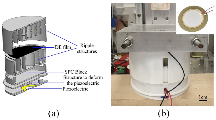
(a) Schematic of the DEAmPx prototype. (b) Photograph of the fully assembled prototype attached to a linear actuator. Photograph of the PZT diaphragm is shown at the top right.
The DE film is made by pre-stretching an acrylic-based elastomer, VHB 4905, equal-biaxially by about 1.8 times and securing the pre-stretch using a 3D-printed frame. Carbon grease is used as the compliant electrode. The capacitance of the DEG prior to deformation
4. Energy-harvesting performance
We use the circuit as shown in Figure 10 to characterize energy output of the DEAmPx. A voltage divider (R1 and R2) was used to measure the voltage of the DEG
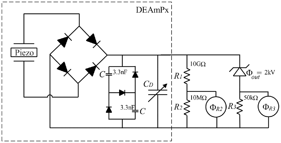
Characterization circuit for DEAmPx. The values of the resistors used are indicated in the figure.
Our experimental results are shown in Figure 11. At the start of the first cycle, when the DEG is fully stretched, the piezoelectric is deformed to prime the DEG and the SPC in series configuration with an input voltage

(a) DEG voltage versus time. (b) Output current versus time.
The mean experimental voltage boost per cycle can be calculated by
In our previous work, we found that the piezoelectric generator working in isolation produces an intrinsic specific energy output of 0.16 mJ/g per cycle under the same loading conditions (Mathew et al., 2019). Our DEAmPx hence demonstrates a net intrinsic specific energy gain of 19 times over that of the piezoelectric working alone (3.1 mJ/g ÷ 0.16 mJ/g), with a system-specific gain of the DEAmPx at three times (0.49 mJ/g ÷ 0.16 mJ/g). The rather small number is a consequence of a very large proportion of mass is taken up by passive piezo and SPC (84%). One may attempt to theoretically scale-up the prototype by inserting more layers of DEGs to allow the system-specific output performance to approach the intrinsic output performance. Assume that the same piezoelectric primes have N number of DE layers. N layers of the DE film electrically connected in parallel will have a capacitance of
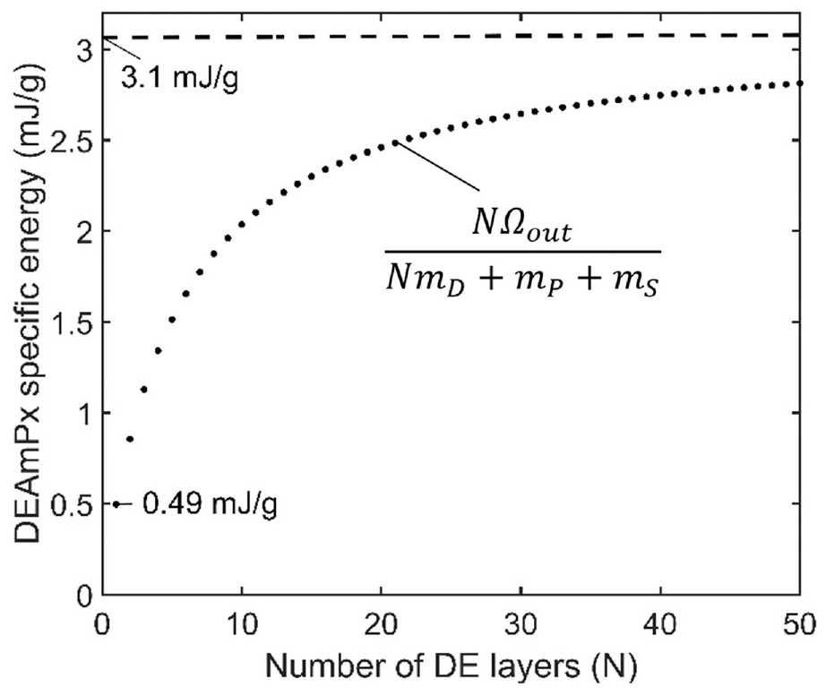
DEAmPx specific energy versus number of layers of DE.
In our previous work, we estimated the mechanical input of DEAmP prototype, which excludes the SPC component, as 860 mJ (Mathew et al., 2019). Taking the ratio of the net electrical energy output (2.3 mJ) of the DEAmPx prototype to the net mechanical energy input of DEAmP prototype, we estimate an approximate value of the efficiency of the DEAmPx prototype as 0.26%. The low value of the conversion efficiency is mainly attributed to the viscoelastic loss of VHB (Mathew et al., 2019). Substituting VHB with an elastomer of lower viscoelastic loss may significantly increase the prototype efficiency. In our experiments, we applied a low-frequency (1 Hz) motion to match with that of a human heel strike. Operating the prototype at very low frequencies may lead to charge loss that may hinder the voltage boost and reduce the output energy. At high frequencies, a highly viscoelastic material may not get sufficient time to retract back to the undeformed state
5. Single-layer DE generator powering DE actuator systems
DEAmPx produces outputs with high voltage (in the order of kV) and low current (in the order of µA). Hence, the generator must ideally find applications that match its output. A most direct application would be to use it to power a DEA. A DEA requires voltage in the order of kilovolts to achieve observable voltage-induced deformation (Huang et al., 2012; Lu et al., 2012; Pelrine et al., 2000). Subject to an electric field, the DEA experiences electrostatic force of attraction (Maxwell stress) that thins down the membrane and expands its area (Pelrine, 2000; Pelrine et al., 2000). The high electric field is supplied using an external high-voltage source, which is in general, bulky, and expensive. Anderson et al. (2012) proposed the coupling of the DEG and the DEA due to the similarity of their physical processes in terms of energy transduction. However, they have yet to demonstrate a working system of their proposal. Here, we demonstrate the actuation of DEAs using the DEAmPx prototype, making it free from an external high-voltage source. Two configurations of the DEA are chosen for the demonstration: a circular DEA (Koh et al., 2011b) and a DE minimum energy structure (DEMES) (Kofod et al., 2006) in the form of a flapping wing.
A circular DEA consists of an electrode active area at the center of a pre-stretched elastomer membrane, secured by a rigid ring (Figure 13(b)) (Koh et al., 2011b). To obtain a visible actuation strain for the DEA within the voltage range of the DEAmPx prototype (0 to ∼2000 V), we applied an equal-biaxial pre-stretch of four times on VHB 4905 and secured using a 3D-printed frame. The diameter of the active area and inactive area was 1.5 and 8 cm, respectively. Carbon grease is used as the electrode material. The electrical connection is identical to that is shown in Figure 4, where the output capacitor is the DEA. However, since the DEA deforms with voltage, the output capacitance is now a function of voltage
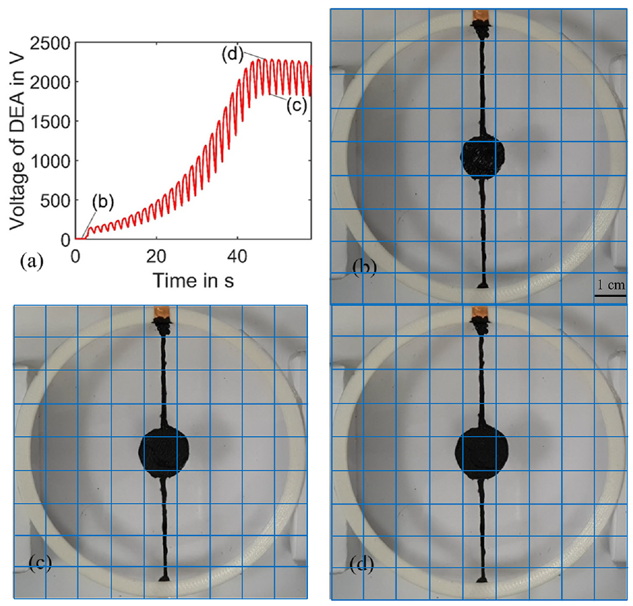
(a) Voltage across the circular DEA powered by DEAmPx. (b) Uncharged DEA at 0% area strain. (c) DEA at 1800 V, 34.55% area strain. (d) DEA at 2250 V, 49.48% area strain.
Figure 13(a) plots the voltage across the circular DEA powered by the DEAmPx prototype. At the beginning of the operation, the voltage across the DEA is zero. It takes 25 cycles for the voltage to reach a maximum value of ∼2250 V. Our loss-free voltage plot, Figure 6(b), suggests that the voltage across the DEA
We demonstrated the actuation of a circular DEA using DEAmPx and achieved areal strains up to 50%. We now demonstrate another type of DEA with a bending characteristic, DEMES. We prepare DEMES as follows: VHB 4905 is pre-stretched equal-biaxially by four times and adhered to a triangular shaped thin plastic frame (∼150 μm) as shown in Figure 14. The excess elastomer is cut off to achieve a final shape where it becomes a self-organized minimum energy structure (Figure 14) (Kofod et al., 2006). When a voltage is applied, the introduction of Maxwell stress reduces the mechanical stress within the DEA which allows the DEMES to change its shape in response to the voltage. The diode that is used in series with the circular DEA for the previous demonstration (Figure 4) was removed to allow a larger voltage swing for the DEMES (Figure 15(a)). The high-voltage swings on the DEA result in a wider motion sweep which is suitable for a flapping mechanism. In the absence of the diode, the DEA is connected in parallel with the DEG. Hence, the new minimum capacitance of the DEG becomes
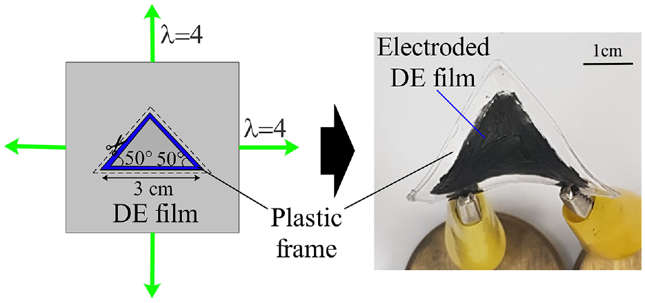
Schematics of the preparation method and photograph of the final shape of the DE minimum energy structure (DEMES). The dimensions of the DEMES are taken arbitrarily.
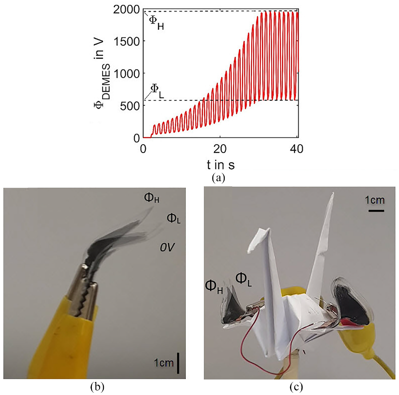
Demonstration of DEMES powered using DEAmPx. (a) Voltage versus time for the DEMES showing a large voltage swing between Φ H and Φ L . (b) Close-up view of a flapping mechanism using DEMES. (c) Flapping mechanism attached to an origami bird.
6. Conclusion
A piezoelectric element is used as the initial charge source for the self-primed DE to create a truly autonomous self-amplifying dielectric-elastomer-amplified piezoelectric (DEAmPx) generator. Ignoring the dissipative processes, a simplified analysis of the system attached to an output capacitor was performed to predict the states of the components (DEG, SPC, and output capacitor) during the mechanical deformation of DEAmPx. From analysis, we found that the voltage boost per cycle of the SP-DEG increases with the DE capacitance ratio
Footnotes
Declaration of conflicting interests
The author(s) declared no potential conflicts of interest with respect to the research, authorship, and/or publication of this article.
Funding
The author(s) disclosed receipt of the following financial support for the research, authorship, and/or publication of this article: This research was supported through funding from the first grant call under the Joint Science and Technology Research Cooperation between the Department of Science & Technology (DST), Govt. of India and the Agency for Science, Technology and Research (A*STAR), and from the NUS MOE strategic grant for Composites Engineering and Research. S.J.A.K. wishes to acknowledge the A*STAR-DST grant no. R-265-000-524-305 (SERC 142 520 3140) for funding this research. Anup Teejo Mathew and Vo Tran Vy Khanh wish to acknowledge the NUS Research Scholarship for their PhD study in NUS from August 2015 to August 2019. Financial support for Liu Chong from NUS MOE strategic grant R-265-000-523-646 is gratefully acknowledged.