
Abstract
In the present work, both theoretical and experimental investigation of a vertical cantilever beam–based piezoelectric energy harvester are carried out under principal parametric resonance condition. A piezoelectric patch is attached near the fixed end of the cantilever beam along with an attached mass positioned at an arbitrary location. The extended Hamilton’s principle is used to derive the spatio-temporal equation of motion, and generalized Galerkin’s approximation is used to obtain the temporal nonlinear electromechanical governing equation of motion. The method of multiple scales is used to find the reduced modulation equations. Due to large transverse deflection and effect of rotary inertia of the attached mass, the system exhibits cubic and inertial nonlinearities. An experimental setup with slider crank mechanism–based shaker and a harvester consisting of a cantilever beam with piezoelectric patch and attached mass is designed and developed. The challenges posed by parametric resonance in crack development in the PZT and in the beam are reported. The theoretical and experimental output voltage and the power obtained are found to be in good agreement. Furthermore, a qualitative and quantitative comparative study of 17 energy harvesters has been carried out, and the normalized power densities have been compared.
Keywords
1. Introduction
The recent advancements in the field of sensors and actuators drastically reduce the power consumption of micro-electronic devices (Mahmoudi and Iniewski, 2016; Meindl, 1995). The next generation devices need to be self-reliant in the energy front. In this regard, these devices must be equipped with certain energy-harvesting unit, which should be capable of extracting energy from ambient sources. Available ambient energy in the form of solar, wind, flowing water, and vibration is sufficient to power such devices. Several transduction mechanisms (Beeby and White, 2010; Priya and Inman, 2009)—namely, electromagnetic, electrostatic, piezoelectric, and electrochemical—are exploited to convert these available energy into electricity. Among them, the piezoelectric-based transduction mechanism has advantage over others because of its high power density (Anton and Sodano, 2007) that makes it suitable for micro-scale applications (Poulin et al., 2004).
PZT materials are employed extensively in sensing, actuation, and energy harvesting purpose. Vibrational energy is converted into electrical energy by structures (i.e. beams, plates, shells, and combination of basic structures) embedded with PZT patches (in
Autoparametric vibration phenomenon is also utilized for energy transduction purpose (Jia and Seshia, 2014) where parametric and autoparametric base excitation shows the superiority over direct excitation. Yan and Hajj (2017) also exploited the autoparametric base excitation to develop a cantilever-based combined absorber and harvester system. Higher order parametric excitation can also be explored as energy harvesters in micro-electromechanical systems (MEMS) at high frequencies (Jia et al., 2016). Bobryk and Yurchenko (2016) reported a significantly improved performance of energy harvester when subjected to the random parametric excitation. Li et al. (2018) studied the coherence resonance of buckled PEH under the stochastic parametric excitation. The nonlinear dynamics of cantilever beam with parametric excitation (Anderson et al., 1996; Cartmell and Roberts, 1987; Dugundji and Mukhopadhyay, 1973; Dwivedy and Kar, 2001; Zavodney and Nayfeh, 1989) is analyzed extensively, where rich nonlinear behaviors—that is, secondary resonances, bifurcations, and chaos—has been observed. In the previous work, Garg and Dwivedy (2019) analytically analyzed a similar PEH system with 1:3 internal resonance between the first two modes. The parametric instability regions along with time and frequency responses are determined, and turning point, pitchfork and Hopf bifurcations are observed. The present study brings light on few challenges pose by the PEH system under parametric excitation.
In the present study, a vertical cantilever-based PEH system is investigated under the harmonic excitation of parametric type. A mass is attached at an arbitrary position along with a piezoelectric patch (PZT-5H). Hamilton’s principle is used to find the governing equations, which involves cubic and inertial nonlinear terms along with electromechanical coupling terms. The method of multiple scales is applied to reduce the second-order nonlinear equation to the first-order form. An in-house shaker is developed to provide harmonic excitation for experimental investigations on the PEH system. The frequency response from analytical and experimental work is compared and analyzed. The parametric excitation causes very large and violent deflection of the cantilever beam system, which brings the challenge of dynamic stability of the system and the durability of the piezoelectric patch attached to it. Large deflection may cause crack in the beam system, which not only breaks the beam from the base (which is also observed by Zavodney and Nayfeh (1989) and by present experimental work) but also severely damages the PZT patch. How these challenges affect the voltage response of the system is investigated in the present work.
2. Design and development of the experimental setup
The objective of this work is to develop a low-cost shaker to provide parametric excitation to the energy harvester. The requirement of the frequency of excitation, amplitude (stroke length), specimen dimensions, and its weight are the basic parameters on which the design and development of the harvester is carried out. The basic specimen considered in this work is a vertical steel cantilever beam having dimensions of 300 mm × 25.5 mm × 5.1 mm attached with a unimorph piezoelectric patch (50 mm × 25 mm × 0.5 mm) near to its fixed end. A mass (m) is attached at an arbitrary distance d from the fixed end. The neodymium magnets (rectangular plate form, 25 mm × 10 mm × 1 mm, weight of 4.5-g each) are used as the attached mass here so that the mass and its position are adjustable along the beam. The PZT patch (PZT-5H) by Sparkler Ceramics Pvt. Ltd. is attached near the fixed end of the cantilever beam. The PZT patch is glued on to the beam surface by using Araldite epoxy-resin (Grade AV138M/HV 998) with a 60-40 ratio.
3. Shaker design
A slider-crank mechanism (Figure 1(a)) is used to convert the rotational motion of DC motor to translational motion of the slider. A base plate is taken to mount the DC motor with the slider-crank mechanism and the electronic components. The CAD model of the setup developed using ProE is shown in Figure 1(b). To design the components, initially kinematic and dynamic analysis of the slider-crank mechanism has been carried out.
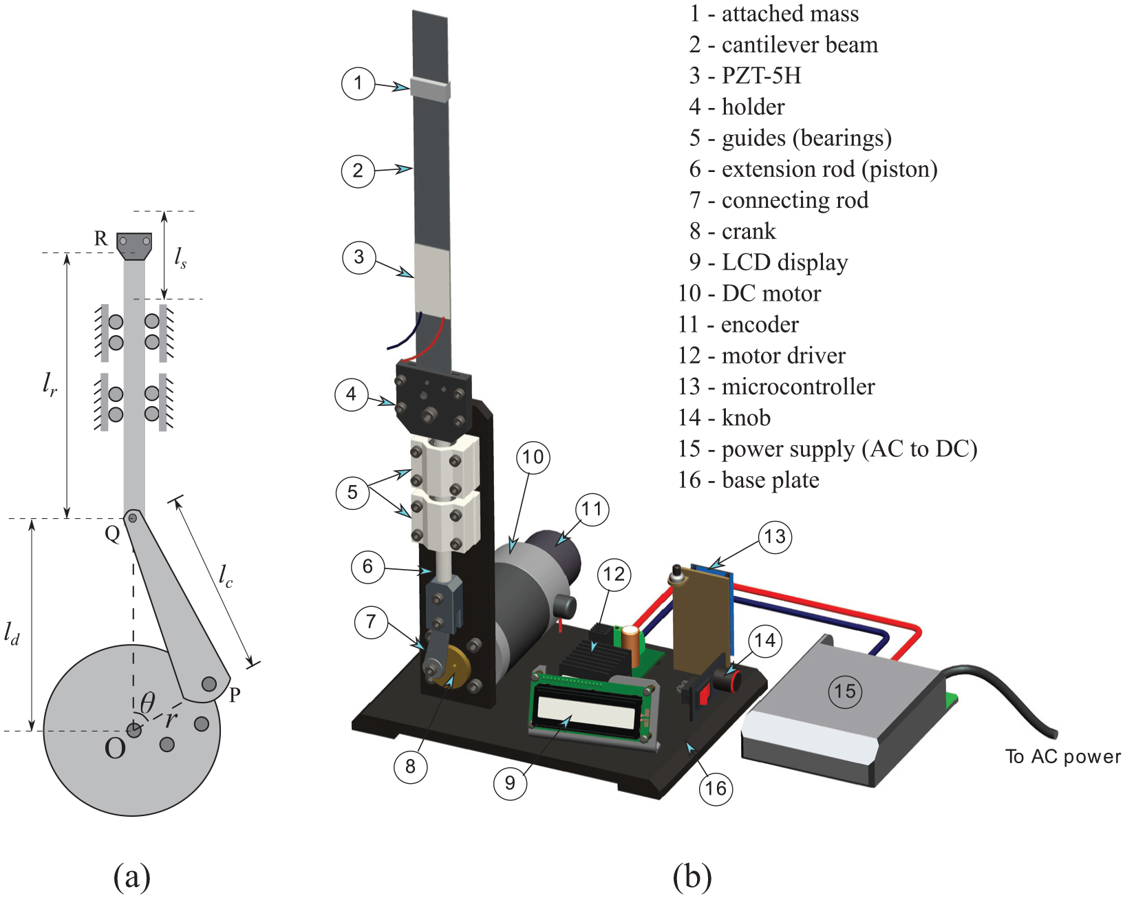
(a) Schematic diagram of slider-crank mechanism and (b) CAD model of the piezoelectric energy harvester (PEH) with different parts.
4. Kinematic analysis
The schematic diagram of the mechanism is shown in Figure 1(a). The mechanism is assumed to have stroke lengths
5. Dynamic analysis
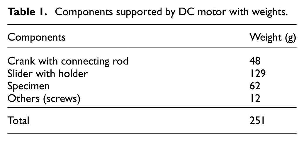
A dynamic analysis is performed to decide the required motor torque to develop the PEH system. The components are made up of mild steel. The components, which are supported by the DC motor with their weights, are mentioned in Table 1. The total load of the basic supporting structure is 251 g.
Components supported by DC motor with weights.
The required torque is calculated using the following expression (Uicker et al., 2011)
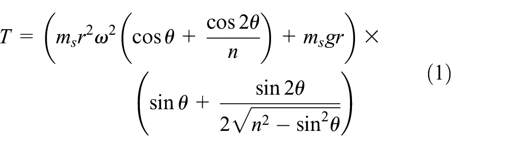
Taking
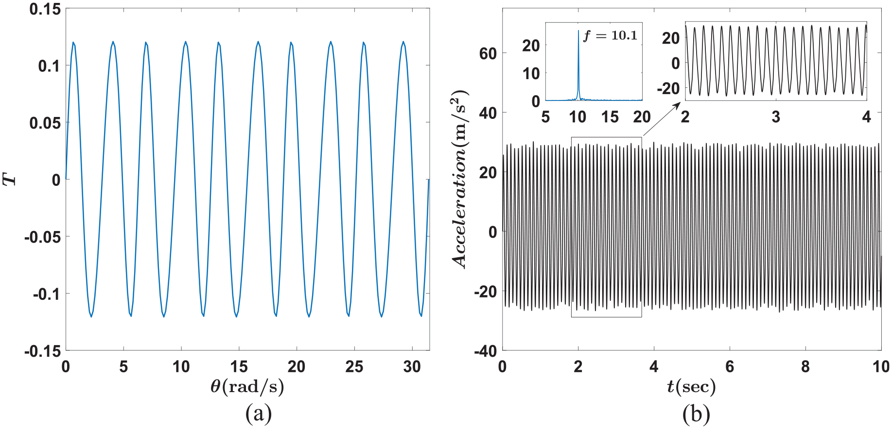
(a) Variation of torque with crank angle and (b) experimental acceleration time response (after filtering) of the holder without beam system attachment at a particular speed of DC motor by using the accelerometer.
Material and geometric properties of the substrate and piezoelectric patch (PZT-5H).
The photograph of the fabricated setup is shown in Figure 3. The encoder is connected to the DC motor to read the rotational speed in cycles per minute. Microcontroller (mbed NXP LPC1768) is programmed in such a way that one can regulate the rotational speed of the DC motor by just rotating the knob and display the output in display unit (16 × 2 LCD). The microcontroller required 5-V DC power, which is provided by USB cable. Power supply converts AC into DC and is connected to the motor driver. The motor driver provides 12 or 24-V power to the motor.
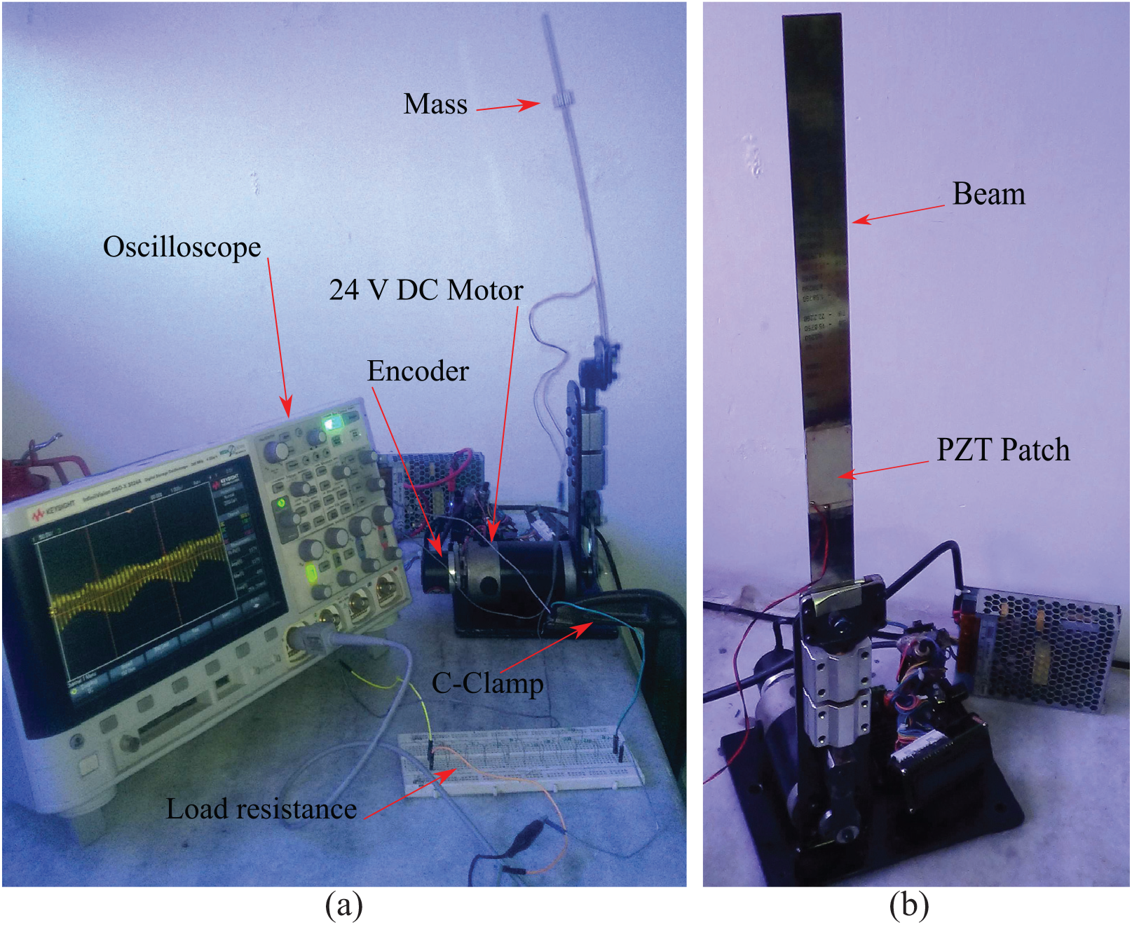
(a) Experimental setup of PEH system with electronic circuit and oscilloscope and (b) the harvester with PZT patch.
6. Analytical model
The schematic diagram of parametrically excited PEH system consists of a cantilever beam of length L, mass m at a distance d from its fixed end, and a PZT patch of length
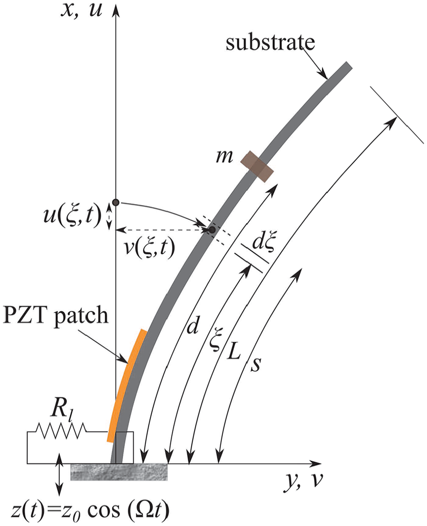
Schematic diagram of piezoelectric energy harvester (PEH) system with parametric excitation.
The nondimensional nonlinear coupled electromechanical temporal governing equations of motion of the system are expressed in the following equations. The detailed derivation can be found in Appendix 1
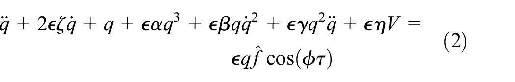

where,
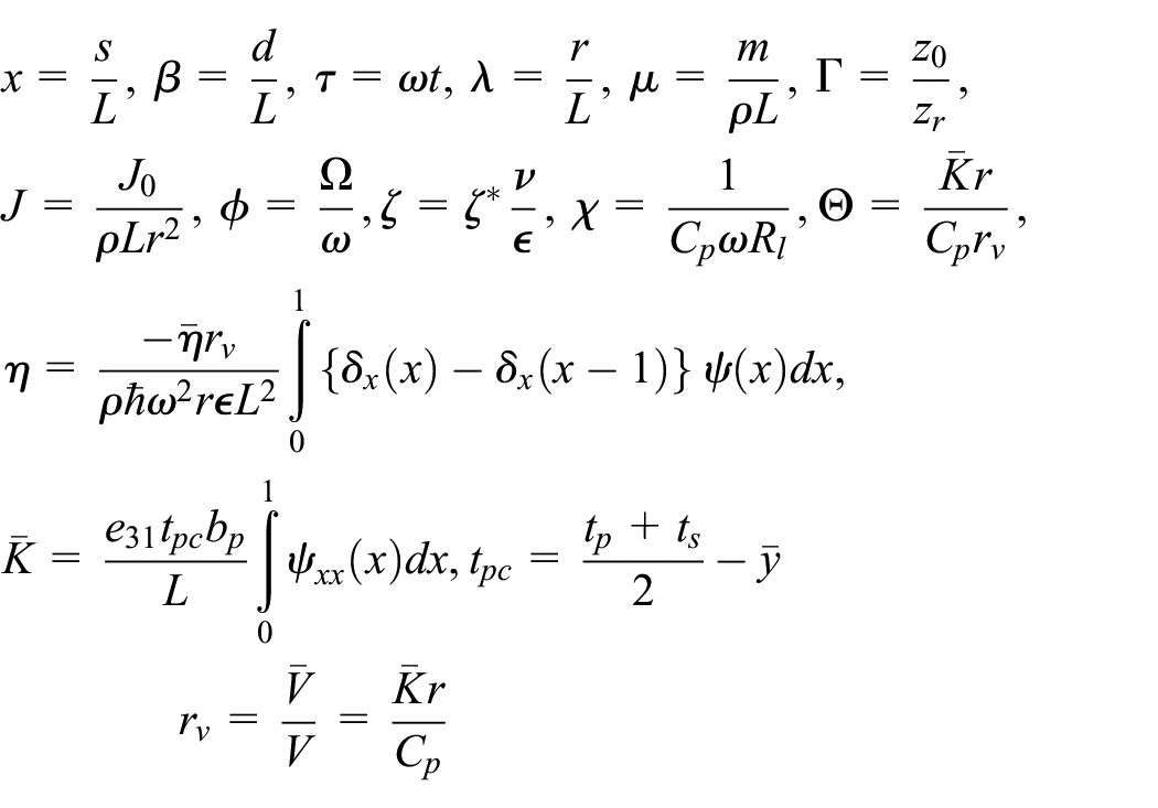
where
7. Perturbation analysis
A uniform first-order approximate analytical solution of equations (2) and (3) is obtained by using the standard method of multiple scales. In the present work, the nonlinear electromechanical system is explored as an energy harvester for the principal parametric resonance condition. The time dependence is expressed into multiple time scales as


Substituting equations (4) and (5) into equations (2) and (3) and further equating the coefficients involving the terms of


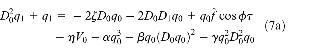

The solution of differential equations (equations (6a) and (6b)) of the order

where cc is the complex conjugate of the preceding terms and
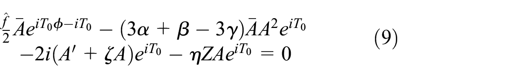
One may obtain similar expression for single-mode approximation without considering 1:3 internal resonance case from Garg and Dwivedy (2019). To express the nearness of

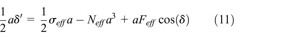
where

where
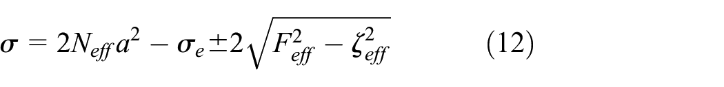
The above expression is parabolic in nature with respect to the nondimensional amplitude a. Steady-state displacement, output voltage, and power are obtained from the following expressions

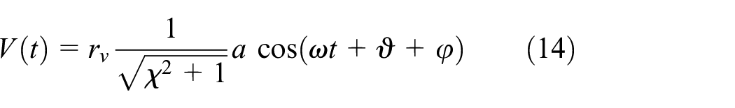
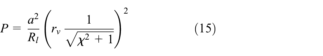
here
8. Results and discussion
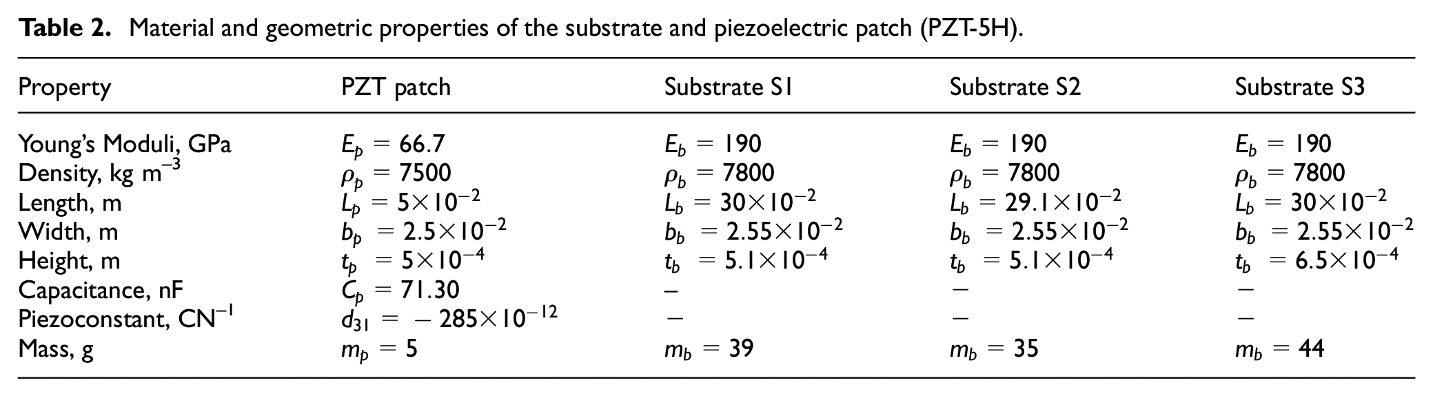
For result and discussion purpose, the geometric and material properties of the specimen (cantilever beam and piezoelectric patch of PZT-5H) as shown in Figure 1(b) are given in Table 2.
It may be noted that a mass of 27 g is attached at a distance of 213 mm from the base of the system. Furthermore, the PZT is placed at a distance of 5.7 mm from the fixed base. Initially, the free vibration response of the system is found out to obtain the natural frequency and the damping ratio of the system. Figure 5(a) shows the voltage–time response of the harvester, which is obtained experimentally by simply tapping the end of the harvester in open circuit condition. As the voltage is proportional to the displacement of the system, using the logarithmic decrement method, the damping ratio of the system is found to be 0.0134.
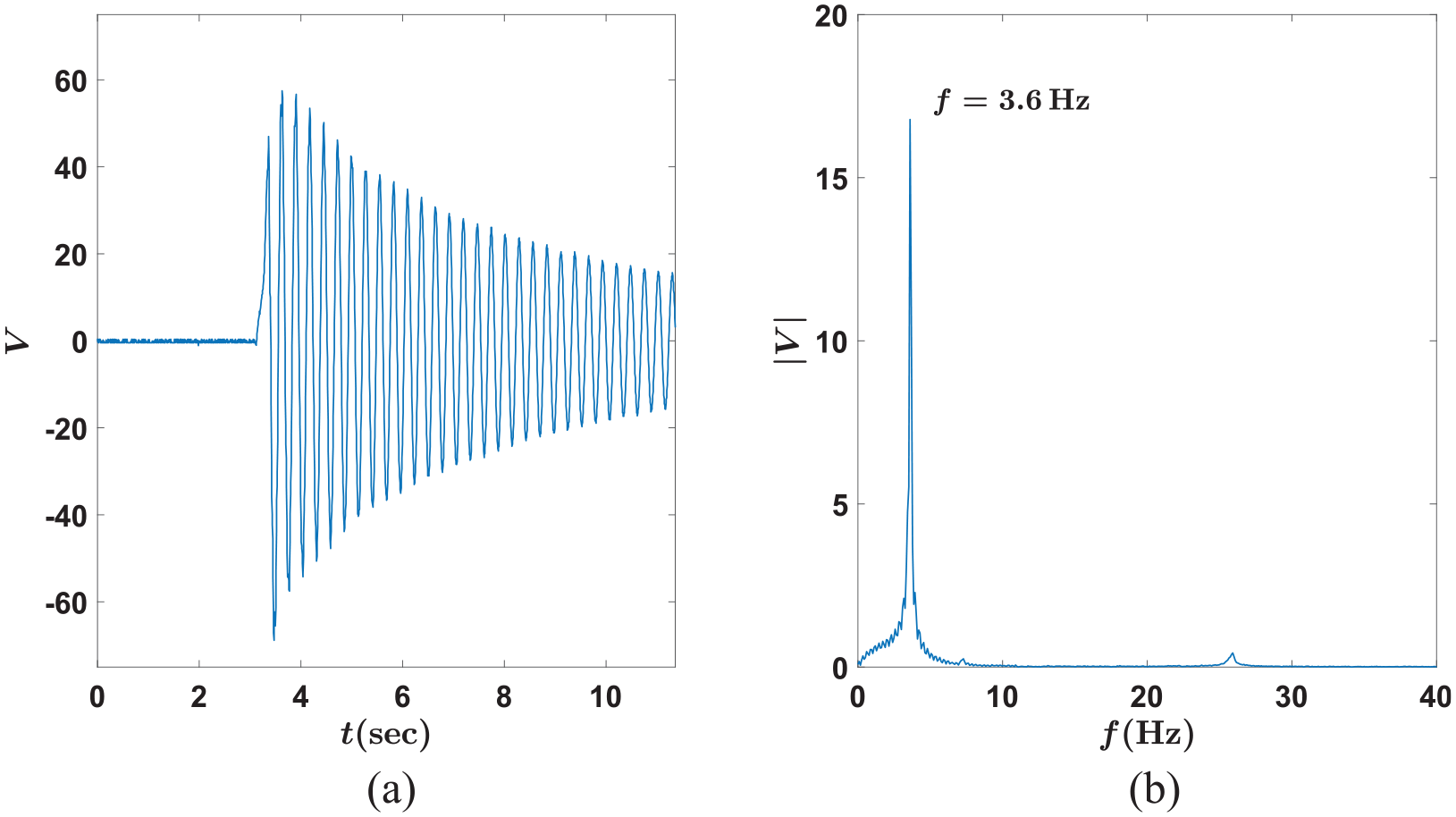
(a) Open circuit voltage–time response of the system when just tapping the top edge of the beam for damping coefficient calculation by logarithmic decrement method and (b) corresponding FFT of the voltage–time signal.
The corresponding FFT of the voltage–time signal is plotted in Figure 5(b), where the fundamental frequency of the PEH system is found to be 3.6 Hz. By using the expression given in Appendix 2, the natural frequency of the system is found to be 3.53 Hz. Figure 6(a) shows the frequency response plot obtained by using equation (12). The external load resistance is kept at
Therefore, the piezoelectric patch does not undergo any strain and hence, no voltage is produced (Figure 6(b)). Furthermore, sweeping up this frequency, after this critical value where it undergoes supercritical pitchfork bifurcation (
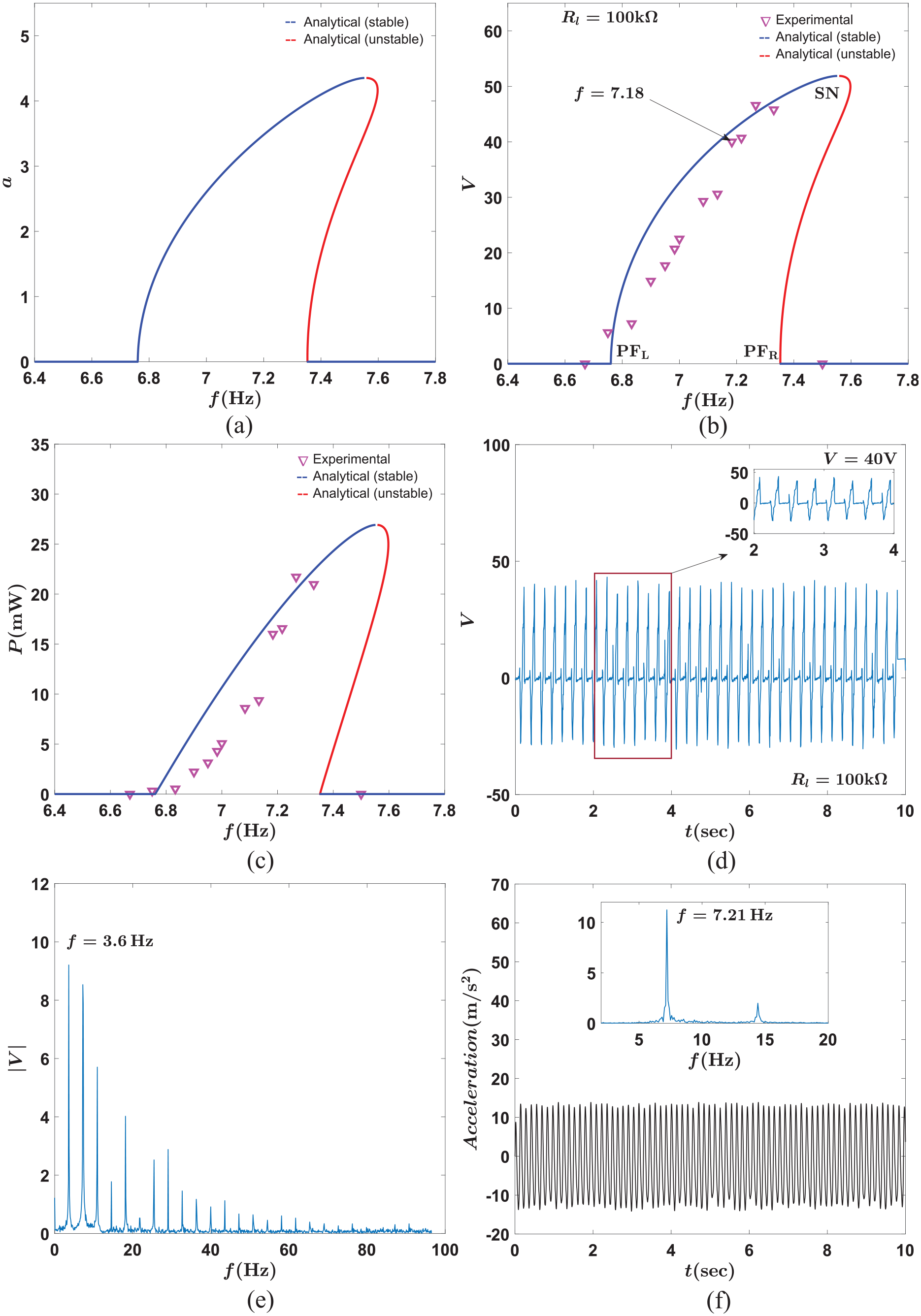
(a) Amplitude response with frequency of excitation at
To compare the analytical result with experimental result, the system is excited near to twice its fundamental frequency (
The difference between experimental and analytical findings may be due to the parameter taken for theoretical analysis and minor imperfection in the experimental setup. The theoretical prediction of critical threshold frequency and the highest output voltage closely resembles the experimental findings. It may be noted that the error is found to be around 2% near the supercritical pitchfork bifurcation point and saddle-node bifurcation point. In between these points the error is coming to be around 10–15%. The error is calculated as the ratio of the total deviation in output voltage by total theoretical voltage. Also one may note that the analytically predicted response consists of stable (solid blue lines) and unstable (solid red lines) nontrivial branches of fixed points, which coincides with experiment findings.
The steady-state power is then calculated as shown in Figure 6(c). One may achieve a maximum power of nearly 22.7 mW around a frequency of excitation of 7.25 Hz for external load resistance of
When the harvester system is excited near the parametric resonance condition, few hairline cracks are observed transverse to the length of the piezo-patch (Figure 7(c)). This is because the patch is placed near to the base (spanned from 5.7 to 10.7 mm length from the base) where the bending moment is high and large amplitude of vibration causes PZT patch to break transversely and visible hairline cracks appear due to the brittle nature (low Young’s modulus) of patches. Due to these cracks, the time response (shown in Figure 6(d)) differs from well-expected continuous periodic profile and sharp peaks rather than smooth variations are visible. Here, near the SN bifurcation point the beam may develop cracks close to the fixed end due to high transverse deformation, which produces maximum bending moment at the base, and after few cycles the beam may break as shown in Figure 7(a). The corresponding close-up figure is shown in Figure 7(b), where the direction of the crack is transverse to the length of the beam. This could be further quantified in terms of the amplitude of the base acceleration, which is responsible for the onset of a crack in the beam. From the expression of the base excitation (
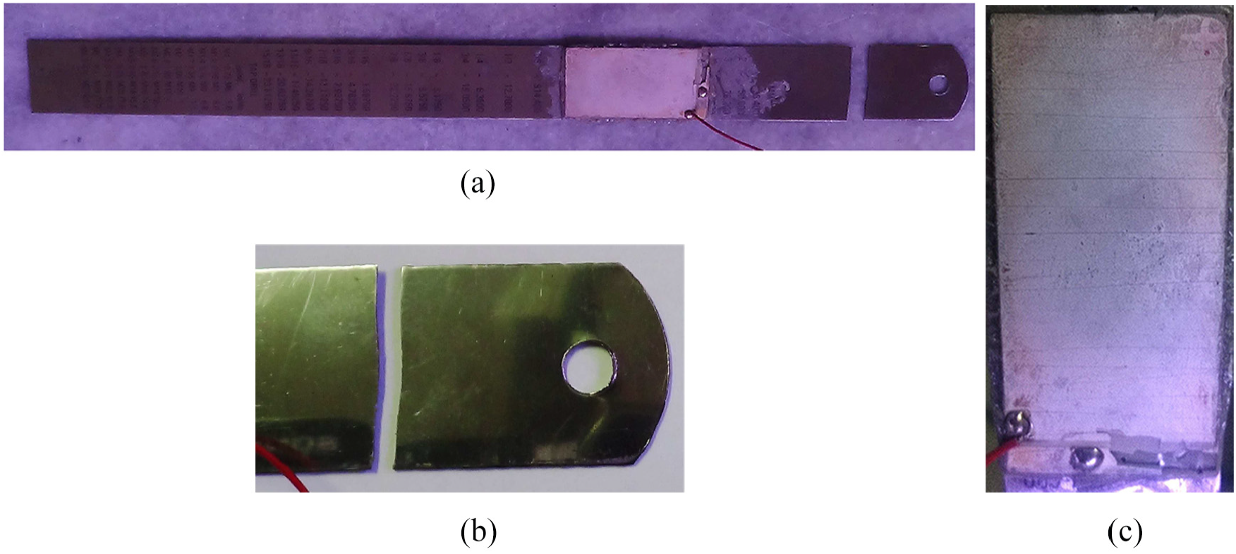
(a) Cracked beam with piezo-patch, (b) cracked beam (zoomed view), and (c) piezoelectric patch (PZT-5H) with visible hairline cracks in transverse direction and disintegration near the electrode separation.
The length of the beam after disintegration (Figure 7(a)) from near its fixed end is reduced to
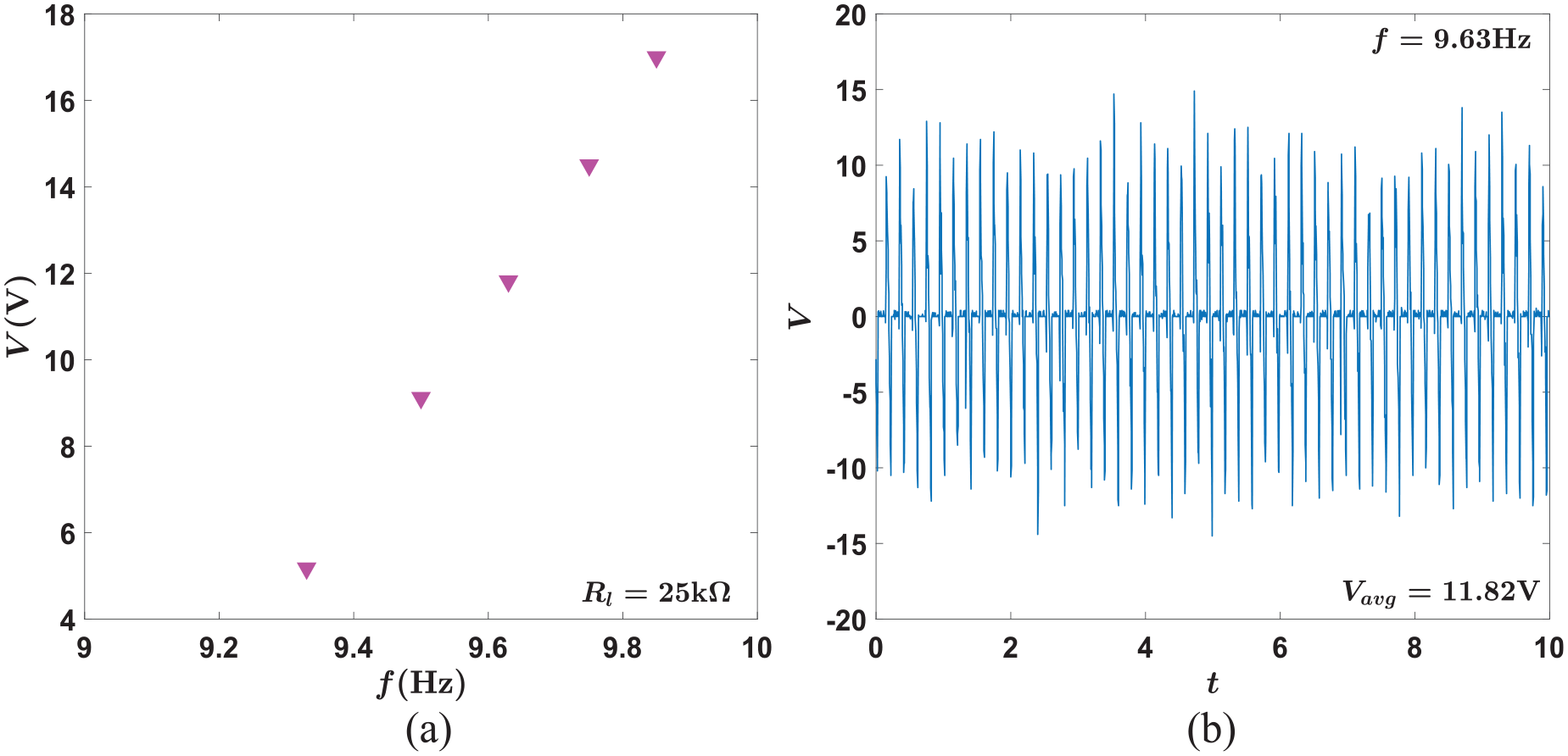
(a) Experimental voltage response with frequency of excitation at
The voltage–time response corresponds to
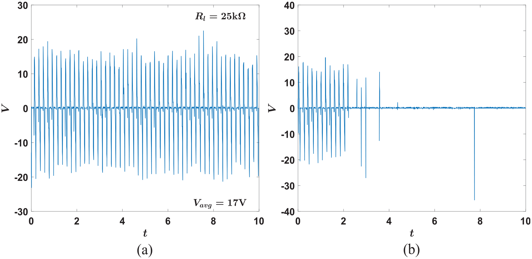
Experimental time response of output voltage at
Since the PZT patch disintegrated in the previous experiment, a new specimen is fabricated for further analysis. The new specimen (with substrate S3) is having all the material and geometric properties similar to previous specimens with substrates S1 and S2 (as mentioned in Table 2), except the thickness. The beam thickness (
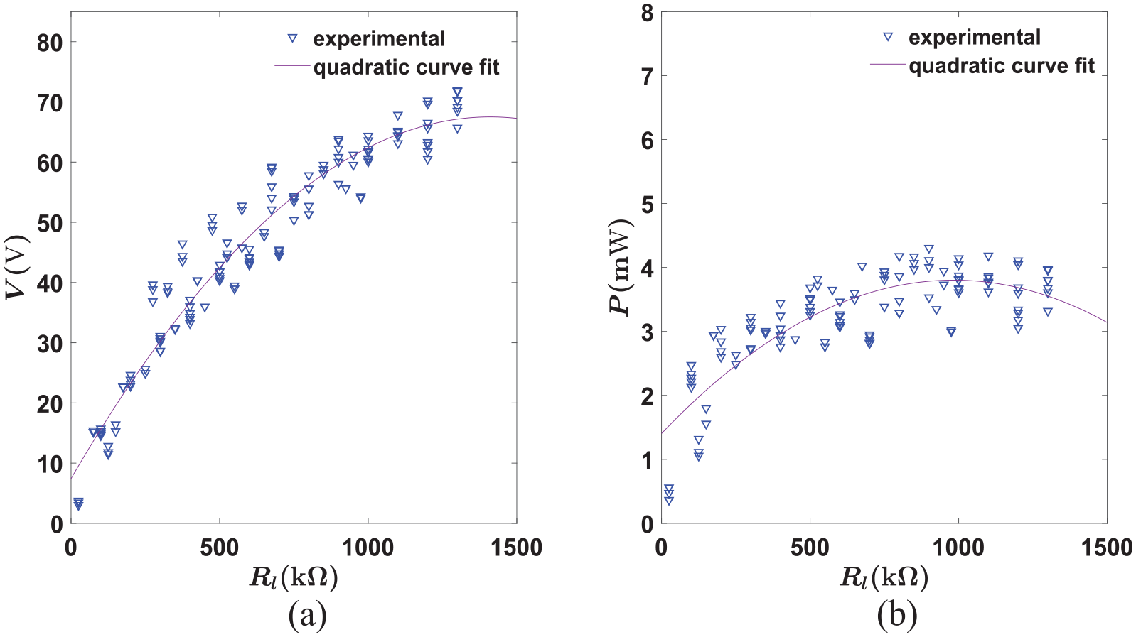
Experimental voltage and power output with variation of load resistance
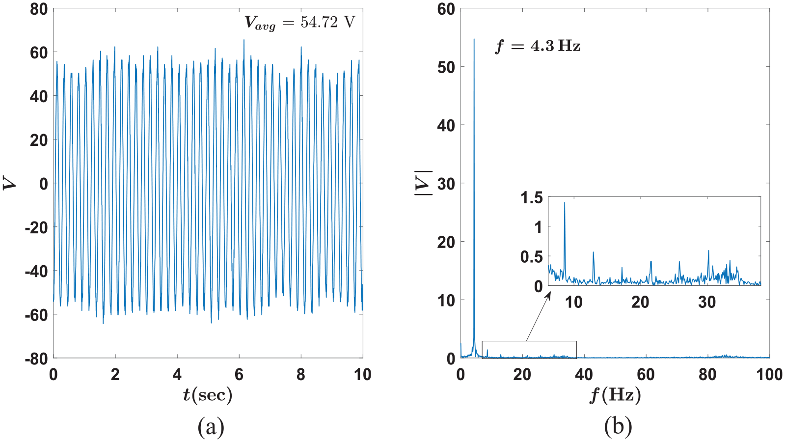
Experimental (a) voltage–time response for load resistance
The continuous and smooth variation of the voltage–time response means the PZT patch is working well, and there is no evident hairline crack is developed until now, at this frequency level. The average value of voltage amplitude is nearly 54.72 V. The participation of other higher harmonics of fundamental frequency is shown in an insight zoomed figure in Figure 11(b) where their participation is weak as compared to the fundamental harmonic. The amplitude modulation may be due to certain imbalances, which causes minor irregularities in energy transfer.
In Figure 12, the variation of output voltage with nondimensional distance (
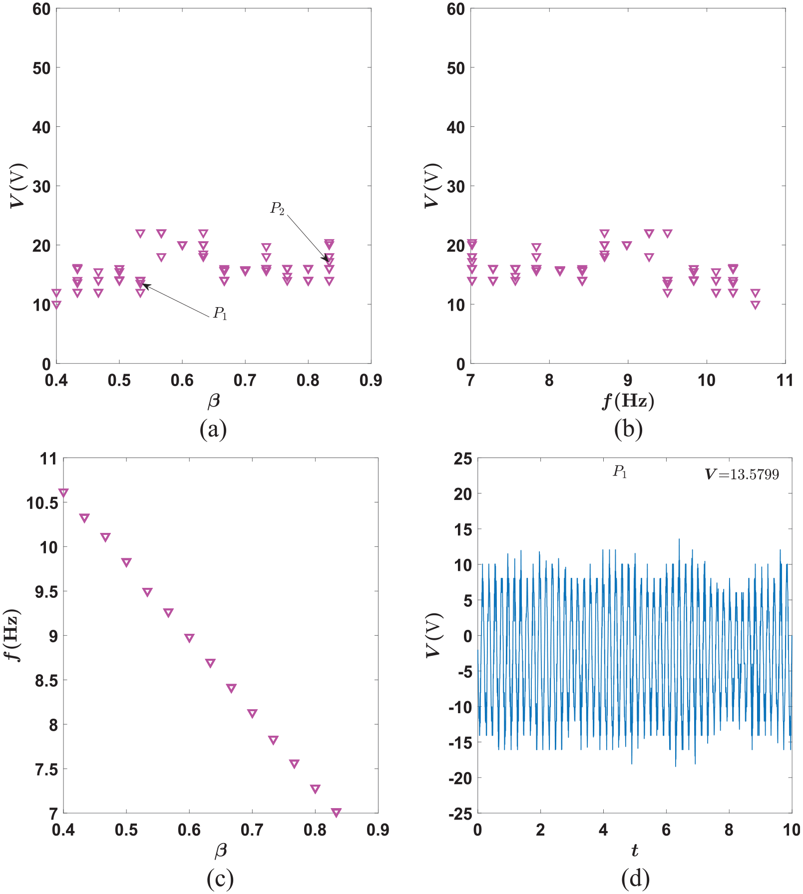
Experimental findings of (a) voltage with nondimensional distance of mass from the fixed end of the beam (
The voltage–time response at point
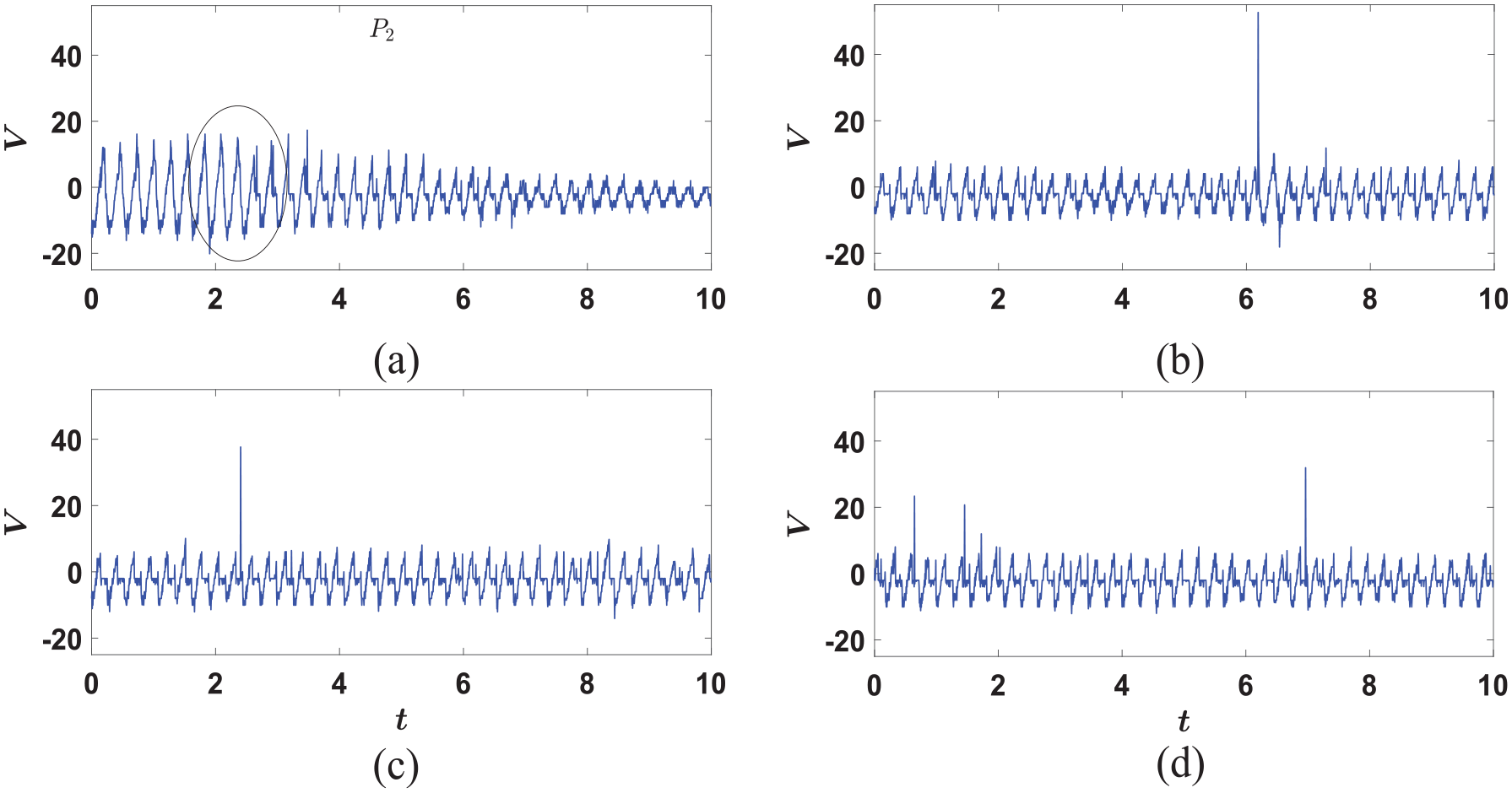
Experimental findings of voltage–time response, where mass
This is probably the first time when time response from a broken patch is analyzed. However, to avoid such kind of disruption in energy transduction two possible solutions are suggested. First, the large amplitude vibration may be restricted by using stoppers and second, the more flexible MFCs (micro-fiber composites) may be used instead of using brittle PZT patches. Apart from MFCs, a wide range of flexible piezoelectric materials (Dagdeviren et al., 2016) are available, which can be integrated into the structures to not only harvest energy but in wearable devices for sensing purpose as well. It also allows using post-buckle structures and curved surfaces. However, use of MFC slightly increases the cost of the system. Another challenge is to avoid the cracks near the fixed end of the cantilever beam system for long-lasting use and keeping the structural integrity intact. The best way to avoid this failure is by providing concave-shaped supporting structure of suitable radius (Kluger et al., 2015) to the base attachment element (holder) or using stoppers (Searle et al., 2018) to prevent large transverse displacement. The provision of mass at an arbitrary position and its value adjustment is helpful to tune the frequency of the harvester as per the available ambient frequency of excitation.
A qualitative comparison of several energy harvesters is presented in Table 3. Comparison has been made based on the type of used piezoelectric patch (viz. PZT, MFC, or PVDF), its configuration (unimorph or bimorph), type of external excitation (direct or parametric), orientation of the specimen (horizontal or vertical), nature of study (analytical or experimental), length covered by the piezoelectric patch (partial or full), and transduction mechanism utilized (piezoelectric or electromagnetic). One sample case (Daqaq et al., 2009) is described here, and the interpretation in a similar manner for the other cases can be drawn from Table 3. Daqaq et al. (2009) were the first to analyze energy harvesting via parametric excitation. In this work, a lumped parameter model of the cantilever beam with a tip mass and MFC patch is used. The beam is kept in the horizontal position in this experimental study. It may be noted that in the present work, the cantilever beam is placed in the vertical position where the effect of gravity is accommodated in the dynamics of the system. Also, the mass can be attached to any arbitrary position along the beam, and PZT-5H patch is used in the present work. Abdelkefi et al. (2012) studied a similar system where a nonlinear distributed parameter model is developed and the effect of nonlinear piezoelectric coupling coefficients on the output voltage and power are analyzed analytically. The unimorph piezoelectric patch spans the whole length of the beam, and any issues in using PZTs under parametric excitation are not reported. Few systems utilized the parametrically excited energy harvesters based on electromagnetic transduction mechanism as well (Jia et al., 2014; Kuang and Zhu, 2019; Yildirim et al., 2016). In such systems, the volume of the system is generally high as compared to the harvesters based on piezoelectric transduction. A combination of direct excitation along with parametric excitation (Mam et al., 2017; Searle et al., 2018; Xia et al., 2019) or autoparametric with parametric (Jia and Seshia, 2014) is also explored for performance enhancement. The emphasis is given on harvesting from low-frequency direct excitation and post-buckled beam system in the work of Friswell et al. (2012). Zhu et al. (2013) and Panyam et al. (2018) explore the effect of axial load in PEH system where the former used piezofilm. Zaghari et al. (2015) analyzed the PEH system with time varying stiffness. In the previous work of Garg and Dwivedy (2019), a system similar to the present one is studied where it undergoes parametric and 1:3 internal resonance. Here due to the internal resonance, the first two modes of the system interacts and the energy transfer takes place between them which helps in extracting more output power and enhances the bandwidth of the harvester. Without considering internal resonance and using unimorph PZT in the limited span instead of bimorph MFC, the system can be reduced to the present system.
Qualitative comparison of the present work with previous literature.

MFC: micro-fiber-composite; U: unimorph; B: bimorph; P: parametric; D: direct; AP: autoparametric; H: horizontal; V: vertical; A: analytical; Exp: experimental; PE: piezoelectric; EM: electromagnetic.
The studies of PEH systems mentioned in Table 3 are extended in Table 4 for the quantitative comparison of the normalized power density (NPD). Here, the parameters considered for the characterization of the harvesting system are the input acceleration, volume, frequency, maximum power output, and NPD. NPD is determined using the expression
Quantitative comparison of the present work with previous literature.
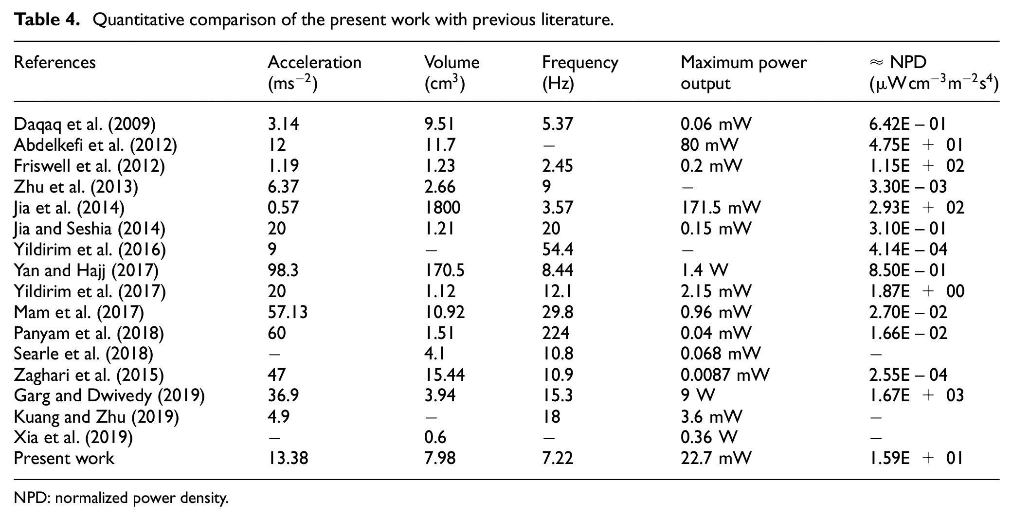
NPD: normalized power density.
In comparison with the previous studies where nonlinear (geometric and inertial type) parametric excited harvesters are analyzed, the present work differs mainly in placing the attached mass in arbitrary position along the beam length and keeping the beam in vertical position instead horizontal in order to let gravity assist in large transverse displacement of the beam system. Also, the present work is the first in reporting the challenges in using PZT and cracks in the beam system due to large deformations where previous works failed to do so. The future work involves the experimental investigation on how in such kind of parametrically excited systems one may bring more stability.
9. Conclusion
In the present analysis, the vertical cantilever beam–based piezoelectric energy harvester under parametric excitation is investigated theoretically and experimentally. The system consists of an arbitrary positioned mass and piezoelectric patch near its fixed end. The nonlinear coupled electromechanical governing equations of motions are derived by using Hamilton’s principle, and method of multiple scales is used to reduce the second-order nonlinear governing equations to a set of first-order reduced equations that are used for finding the steady-state response and the stability of the system. The results from these equations are compared with those available in the literature and by developing an experimental setup.
A shaker with piezoelectric energy harvester is developed to experimentally validate the theoretical findings of the vertical beam-based harvester. The limiting supercritical bifurcation point at which the nontrivial state is observed theoretically is found to be in good agreement from the experimental findings. Furthermore, the theoretical and experimental responses are found to be in good agreement. The maximum output voltage obtained is also found to be in close agreement. The output voltage and power are compared with those found in the literature. It is observed that the present vertical cantilever beam–based harvester nearly produced more output voltage and power than that of a horizontally placed cantilever beam with same configurations. Hence one may use the developed reduced equations for finding the response, voltage, and power for similar piezoelectric energy harvester. A broadband range of frequency between the subcritical and supercritical pitchfork bifurcation points may be used to harvest the energy. The amount of harvested voltage and power depends on the system parameter, which may suitably be adjusted by using the developed reduced equations to harvest more energy. The challenges of cracking in beam and breaking of piezo-patch during experiments are discussed in this work. In addition, some suggestion on how the challenges can be overcome is also discussed for system stability and durability. A qualitative and quantitative comparison of 17 energy harvesters have been carried out, and the present harvester is found to be better than most of the harvesters in terms of the NPD. The present experimental and theoretical investigation will help to overcome the challenges posed by the parametrically excited energy harvester.
Footnotes
Appendix 1
In the present work, the extended Hamilton’s principle
where
The non-conservative virtual work done
The total moment due to piezoelectric patches
Here,
The governing nonlinear equation of motion becomes
Here
where subscript “p” is used to denote terms related to PZT, and
Here
Here
The four boundary conditions at fixed and free ends are represented as follows
At the fixed end, displacement and slope are zero and at the free end, the bending moment and shear forces are zero. By considering single-mode approximation in the Galerkin’s method, the transverse displacement
Appendix 2
Acknowledgements
The authors are grateful to Mr. Arun Borgohain and Mr. Ayushman Gogoi of Yantrabot Pvt. Limited for their help to fabricate the experimental setup.
Declaration of conflicting interests
The author(s) declared no potential conflicts of interest with respect to the research, authorship, and/or publication of this article.
Funding
The author(s) disclosed receipt of the following financial support for the research, authorship, and/or publication of this article: The authors would like to acknowledge the financial support provided by the Department of Mechanical Engineering, Indian Institute of Technology Guwahati.