
Abstract
Shape memory alloy coating on an optical fiber plays an important role in developing novel active thermal sensors in the field of microelectromechanical systems. In this article, a detailed analysis of NiTi alloy deposited over plastic optical fiber was discussed. A detailed investigation of the morphological, structural, and thermal properties of the NiTi-coated optic fiber was conducted. The uniformity, crystallinity, transformation temperatures, and thermal stability of the coatings were measured using differential scanning calorimetry, scanning electron microscopy, X-ray diffraction, and thermogravimetric analysis, respectively. Also, an electrical actuation setup thermo-mechanical test was conducted through Joule heating in which different voltages at varying loads have been used. The sensor characteristic–based parameters (time response and sensitivity) were also calculated. The article presents a complete analysis of experimental results showing the properties and performances of the plastic optical fiber after coating with shape memory alloy.
1. Introduction
Fiber optic sensors have many advantages in the field of engineering structures comprising of the ability to withstand the electromagnetic and radio frequency interference, small dimensions, high resolution, and accuracy with superior capability to transmit signals at long distances. Kuang and Cantwell (2003) and Kuang et al. (2013) discussed a technique for structural health monitoring with the help of a fiber optic sensor. The advantage of measuring the temperature at multiple places within the same fiber as a multi-sensing mode of continuous profiling especially in surveilling long structures such as oil wells, flow lines, pipelines, smart structures, and coiled tubing was discussed by Inaudi and Glisic (2010). Hill and Meltz (1997) discussed the potential applications of plastic optical fiber (POF) and reviewed the promising application fields of optical fiber sensing which are based on the existence of photosensitivity in silica optical fiber. Lee (2003) strongly emphasized on the use and advantages of POF as sensors in real-time environment in the fields of civil, mechanical, material, chemical, and biomedical engineering. Gunther et al. (1994) have developed the high temperature–sensing optical fiber sensor for tracking the ceramic actuator performance and measuring the displacement with its working principle in extrinsic Fabry–Perot interferometer (EFPI) sensor operation. The metal coating enhances the optical fiber cladding surface thermal sensitivity, microstructure enhancement, mechanical strength, and also improves light transmission by reducing the attenuation level, optical nonlinearity, and other deteriorations. For sensing higher temperatures in harsh environments, the waveguide sensor needs to be optimized and coating on the optical fiber provides improved mechanical properties at higher temperatures (Scurti et al., 2017). Previously, metal coatings, such as Pb, Al, Sn, PbSnAg, and InBi, coated on optic fibers by flash evaporation technique, melt spin coating techniques, and so on, acting as thermal sensors had been reported in the literature. Numerical simulation of the optical spectrum for a surface-bonded fiber Bragg grating (FBG) sensor embedded with an elastoplastic metallic coating concerning residual strains over the surface of the structure during strained and unstrained conditions was investigated recently (Kim, 2018). Also, the effect of geometric parameters such as thickness, bonding length, and mechanical parameters of the metallic coating has resulted in residual strain variations and their reflected spectra. A spatial impact source identification method based on a one-dimensional (1D) FBG sensor array for tubular structural application with an effective number of sensors and its arrangement method was investigated for the plumbing pipe structure application. Utilizing optical fiber for telecommunication and shape memory alloy (SMA) for damping has been well explored in the literature but incorporating the combination of both material properties for sensing and actuation are new to the technical field (Mohanchandra et al., 2008a). Distributed sensing is one of the primal and potential benefits of using optical fiber sensor technology (Culshaw, 2004). Li et al. (2014) have developed a user-friendly method for shape recovery deformation monitoring of shape memory polymer deployable structure model based on the measurement from two orthogonally embedded FBG vector sensors. The developed smart structure sample was tested for various static bending angles and the dynamic shape recovery deformation process. Balta et al. (2005) experimented on the closed-loop control methodology for the SMA wires actuation using an optical fiber sensor to calculate the system response under applied load changes. The heat transfer lowers the response time, with an inherent reduction observed from the use of thermal actuation with SMAs. Rao (1997) discussed the applications on microelectromechanical system (MEMS) components–based NiTi thin film. They emphasized on the mechanisms of actuation in work/volume ratio, the miniature NiTi actuated devices based on sputtered products, NiTi films, for the huge commercial market, especially for medical microdevices. As a thin film, NiTi is a superior material to use as a micro-actuator in MEMS, with its higher recoverable strains and recovery forces (Kahn et al., 1998). In the past, researchers like Shelyakov and Terekhov (1995), made a sensor utilizing NiTiCu SMA ribbon covering the endpoint of an optical fiber. Mohanchandra et al. (2008a, 2008b) have prepared NiTi-based SMA-coated optical fiber using a sputtering process which will act as a thermal filter and a thermal sensor NiTi thin film serves many advantages which include increased displacement, higher power density, less operation voltage, and actuation force. NiTi thin film is used where large force and stroke are vital and in conditions of low duty cycles operation, and also in extreme environments such as space, biological and corrosive condition. In this work, NiTi-coated fiber is developed by flash evaporation because flash evaporation will provide more coating thickness in comparison with sputtering (Chandra et al., 2007; Sari and Kirindi, 2008). This study includes characterization techniques such as differential scanning calorimeter (DSC), scanning electron microscopy (SEM), X-ray diffraction (XRD), and thermogravimetric analysis (TGA). For understanding SMA mechanisms and its one-way and two-way shape effect, a study on thermo-mechanical characterization which is named thermal and electrical actuation has been done. The developed sensor can be used as a temperature sensor in applications such as condition monitoring, smart structure sensing, pipeline, oil and gas transmission monitoring.
2. Experimental procedure
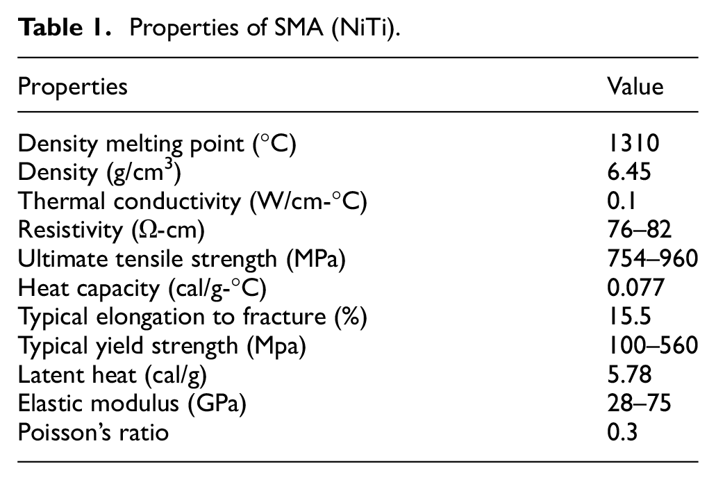
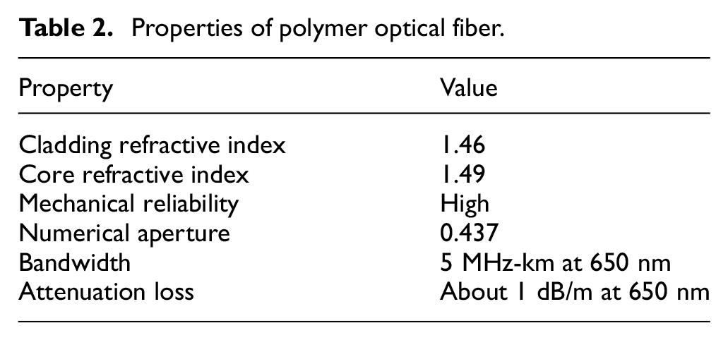
Wires of nickel and titanium (50% Ni and 50% Ti) were used for deposition. From the NiTi phase diagram, an equiatomic composition of nickel and titanium has been selected for better transformation. The NiTi sample has been used for deposition by placing on a tungsten boat in the evaporation chamber and its properties are shown in Table 1 (Huang, 2002). Flash evaporation-based physical evaporation deposition method has been used for developing NiTi thin film on POF with high vacuum condition (5 × 10⁻⁵mbar) and at room temperature. The schematic diagram of the flash evaporation is shown in Figure 1. The POF (1 mm diameter, 0.5 mm core diameter, and 200 mm length) was mounted in an in situ rotatable fixture as shown in Figure 2, which will assist to obtain the uniform deposition of the entire circumference of the fiber. The optical fiber samples are pre-strained 5% using mechanical loading (Abdi et al., 2008). The POF consists of core and cladding structure construction and its properties are shown in Table 2 (Huang et al., 2015).
Properties of SMA (NiTi).
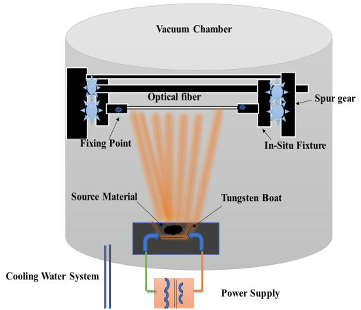
Schematic of flash evaporation deposition setup.
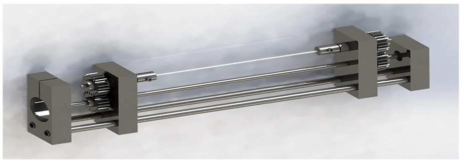
Optical fiber in situ fixture setup.
Properties of polymer optical fiber.
A current of 80 A has been used for evaporating the NiTi samples from the tungsten boat. Using SEM and XRD, the morphological and structural properties of the samples have been characterized, respectively. Phase transformation temperature and thermal characteristics have been analyzed using DSC and TGA.
To explore the suitability of optic fiber in MEMS application, an electrical Joule heating setup was made for the analysis of displacement and bending abilities as shown in the schematic diagram in Figure 3(a). The setup consists of a laser displacement sensor, data acquisition system, Arduino-relay circuit, thermo-optical sensor, and a programmable power supply. The Arduino relay circuit acts as a switch which alternates between heating and cooling of the SMA embedded in the optical fiber for a duty cycle of 15 s. For this actuation analysis, three different loads and voltages such as 35, 50, 75 mg and 2, 2.5, 3 V were used, respectively, as shown in Figure 3(b).
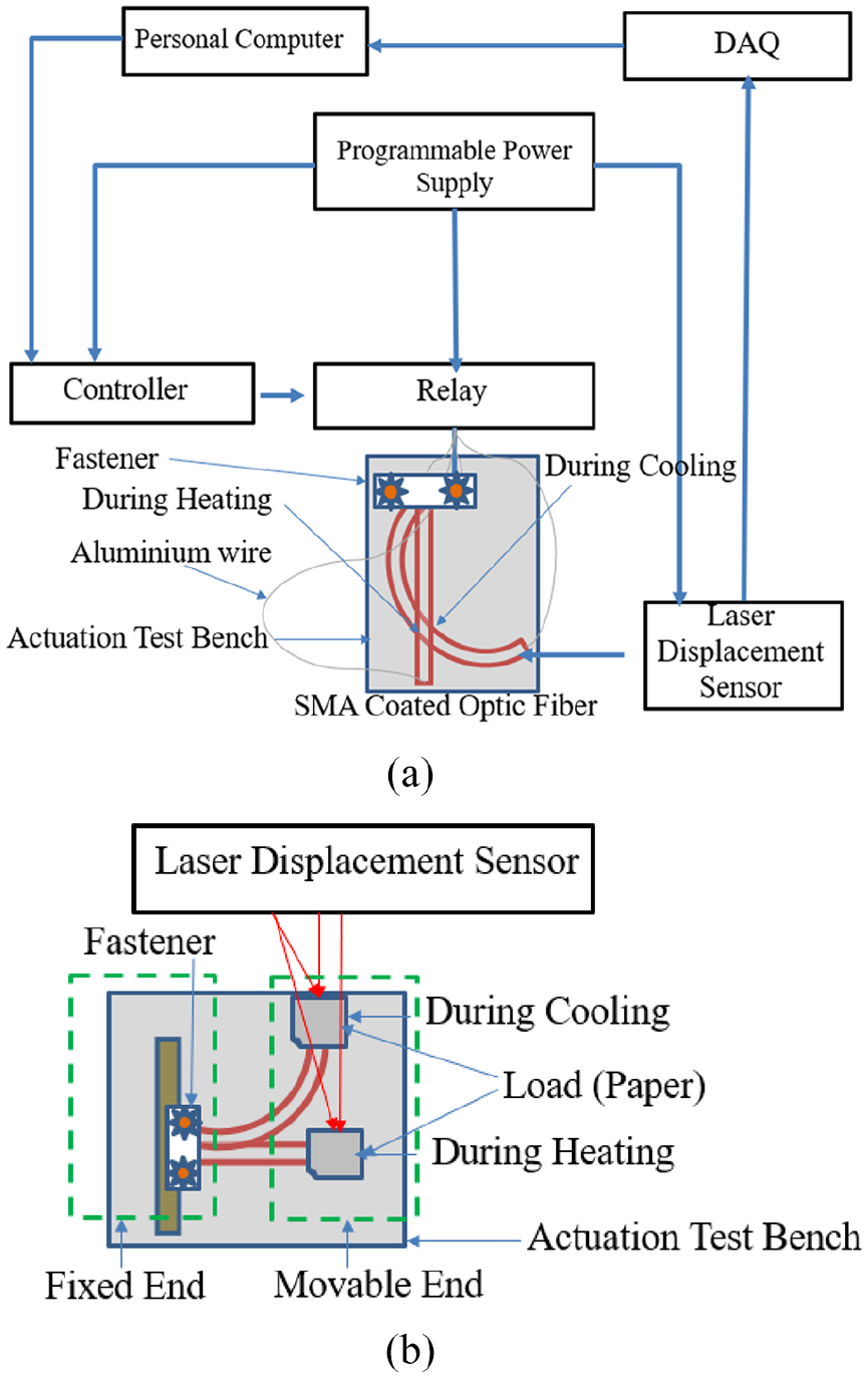
Block diagram of (a) electrical actuation setup and life cycle analysis and (b) mechanical load test.
3. Results and discussion
3.1. Optical microscope result
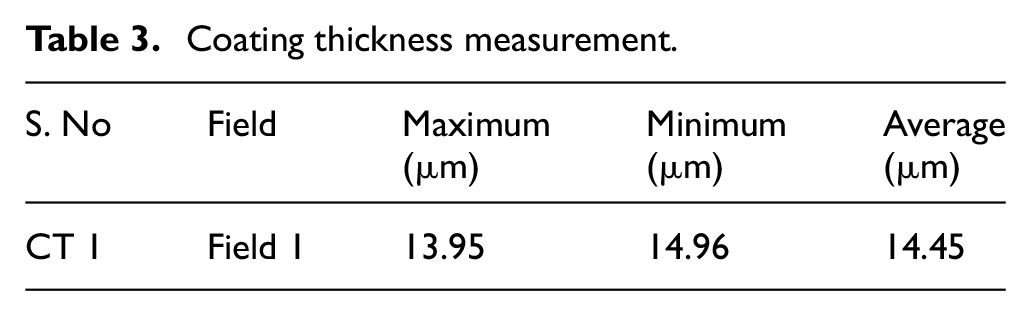
An optical microscope has been used to analyze the NiTi-coated optical fiber thickness and film surface. The thin film surface of the coated optical fiber has exhibited uniformity and layered structure grown by flash evaporation deposition as shown in Figure 4(a). The cross-section of the coated optical fiber is shown in Figure 4(b). The coating thickness and interface sharpness were controlled by rotational speed during deposition (Bunshah, 2000). The thickness of the SMA coating over the optical fiber has been evaluated by optical microscope which is ≈14.45 μm as obtained from Table 3.
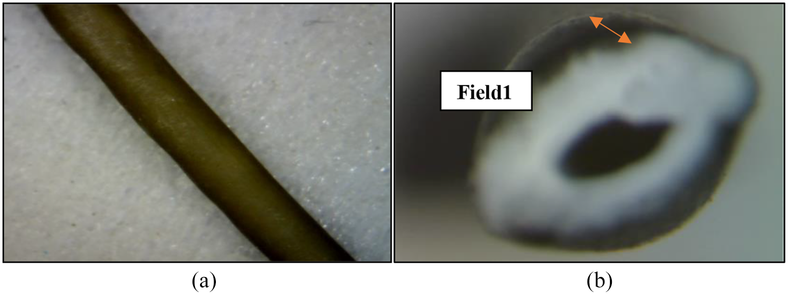
(a) Microscopic images of NiTi-coated fiber and (b) cross-sectional view of the SMA-coated optical fiber.
Coating thickness measurement.
3.2. Morphology results and elemental analysis
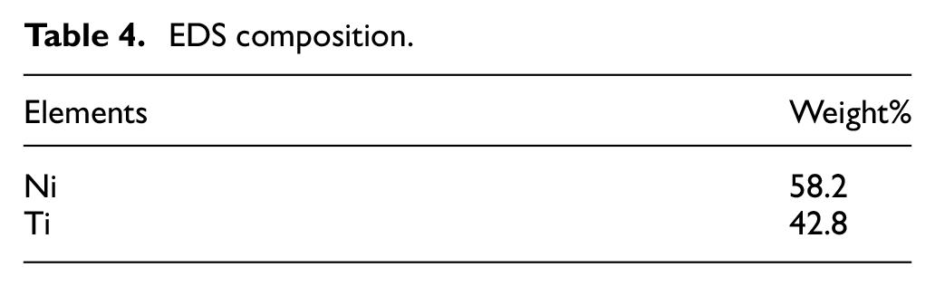
Using SEM, the samples of the NiTi-coated fiber were characterized to examine the morphology of the developed coating. Although the coating appeared to be rough and uneven throughout on a broad view, the surface as observed is layered. This is due to the dissimilar evaporating temperatures of Ni and Ti which are taken in the form of wires due to which it gets coated layer by layer over the fiber and thus the surface appears layered (Bunshah, 2000). The SEM image obtained shows that the film exhibits a typical amorphous microstructure as shown in Figure 5(a). Average grain size was found out to be approximately 330 nm. Also, the micrographs of the cross sections illustrate the presence of columnar grains. Precipitates of nickel are observed throughout the surface. Electron dispersive spectroscopy (EDS) is carried out to determine the compositions of the coatings of NiTi over the optical fiber as shown in Figure 5(b). This was done at 10 different points and then the average was considered for determination. The recorded compositions of the coatings in terms of Ni and Ti after deposition are 58.2% and 42.8%, respectively, as mentioned in Table 4. Minor deviations from the original composition are observed because of the difference in vapor pressure of source material (Sutapun et al., 1998) during deposition.
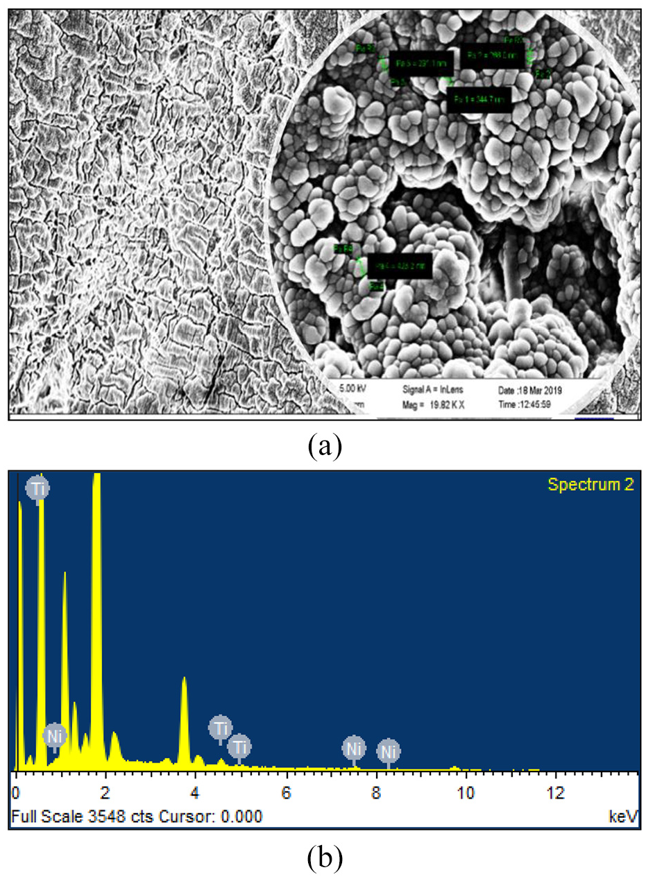
NiTi-coated optical fiber: (a) surface morphology and (b) EDX result.
EDS composition.
3.3. X-ray diffraction
The XRD pattern of NiTi-coated optical fiber is obtained as shown in Figure 6. There are various intermetallic phases identified in the coating, martensitic NiTi, austenitic NiTi, NiTi2 and Ni3Ti. The major high-intensity martensitic peak is observed at 2θ = 44.38° along the plane (0 2 0) which reveals the presence of monoclinic phase there. The film is quite well-crystallized during the deposition process, which may be seen from the plot, as the peak is sharp. At 2θ = 64.7° on the plane (0 1 23) and 2θ = 81.81° at (9 3 1), rhombohedral and cubic lattice structures are observed, respectively. However, these peaks are somewhat broader in comparison with the major peak which shows some amorphous character in them. Various other minor peaks are also observed between 30°C and 85°C. Thus, the fiber coated with NiTi, in the martensitic phase, exhibits a monoclinic structure, rhombohedral structure in the R phase, and cubic structure in the austenite phase. The two-way shape memory effect is amplified in NiTi due to the presence of R phase (Malukhin and Ehmann, 2006). This happened due to the presence of Ni precipitates.
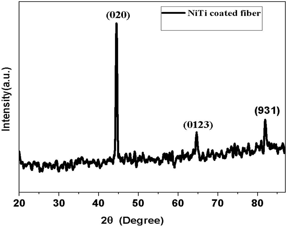
XRD graph for NiTi-coated fiber.
3.4. DSC analysis
Using DSC, a NiTi SMA-coated optic fiber sample of known mass is heated and cooled and the disparities in its heat capacity are measured using the variation in heat flow. The heating and cooling rate were maintained at 10°C/min for this sample. Upon cooling, NiTi alloy shape memory material undergoes austenite to martensite transformation. The lower curve of the DSC plot in Figure 7 shows the endotherm which results when the sample is cooled at a rate of 10°C/min from 140°C to −50°C in nitrogen gas. On heating, the martensite transforms to austenite which yields an exotherm which can be seen in the upper outline of the DSC plot. These transition temperatures are a function of the alloy composition. Apart from this, other peaks are observed at 81°C and at 68.6°C which may belong to plastic fiber (Wang et al., 2016).
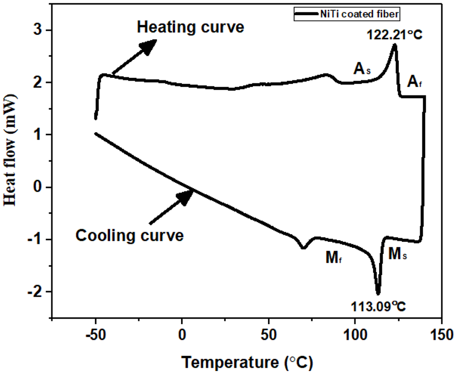
DSC graph for NiTi-coated fiber.
3.5. TGA result
TGA results for both NiTi-coated fiber and bare fiber will undergo a multiple-stage decomposition rate as shown in Figure 8. The rate of decomposition is too less in the initial steps till temperature 214.3°C is almost 5%. After that rapid decomposition occurs in the case of both bare and the coated fibers. The maximum rate of decomposition takes place in the range of temperature 214.3°C–300°C in which 40% of weight reduction occurs because of moisture removal or drying process. The curves show the increment in mass wherever there is a presence of an interactive atmosphere like surface oxidation phenomena, and a small peak is observed at temperature 440°C.
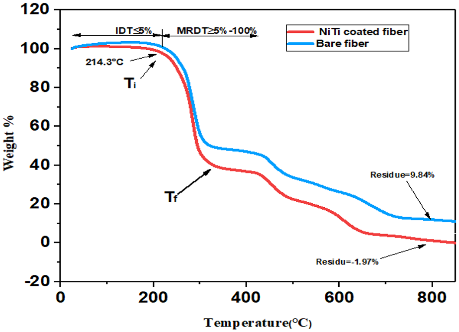
TGA graph for coated and bare fiber.
NiTi-coated fibers have shown a greater rate of decomposition and less mass residue than bare fiber. It has been observed that due to the alloy deposition, the coated optic fiber exhibits a higher degree of heat absorption and results in rapid decomposition when compared with the bare optic fiber. Some nitride compounds formed during this process because of the reaction of the polymer’s elements (C, H, and O) in the presence of nitrogen (Loskyll et al., 2012). The fast decomposition of NiTi test might be ascribed to the capacity of the composites to ingest heat which may result in conduction of the coated samples. The decomposition temperature profile obtained from the TGA graph has been correlated for equating voltage during electrical actuation. From the TGA results, partial melting of NiTi-coated optical fiber samples has been observed after 190°C temperature.
3.6. Hot plate actuation
Hot plate analysis has been conducted for the evaluation of thermal actuation as mentioned in Figure 9(a). During the process of deposition of the SMA over the optical fiber, it was fixed with in situ fixture and it was in the twinned-martensite state. After deposition, the coated fiber was in detwinned martensite because of thermal stress generated during deposition. Both SMA-coated and bare fiber was heated up to 150°C. On heating, the fiber will become straight and after removal from the hot plate, it will regain its original shape. This temperature is different from the DSC phase transformation temperature because of induced stress during the fabrication process. During this test, one end of the fiber is fixed using Kapton polyimide tape and displacement for the other end was taken into the record. In Figure 9(b) and (c), the graph for change in bending angle with temperature has plotted with the help of the hot plate. In NiTi-based alloys, the heat transfer rate is less, which echoes in their change in bending angle. The transformation temperature has decided the shape recovery ratio of the SMA-coated fiber. Using the hot plate analysis, it has been observed that the developed sensor can sense temperature from the range of 70°C–130°C.
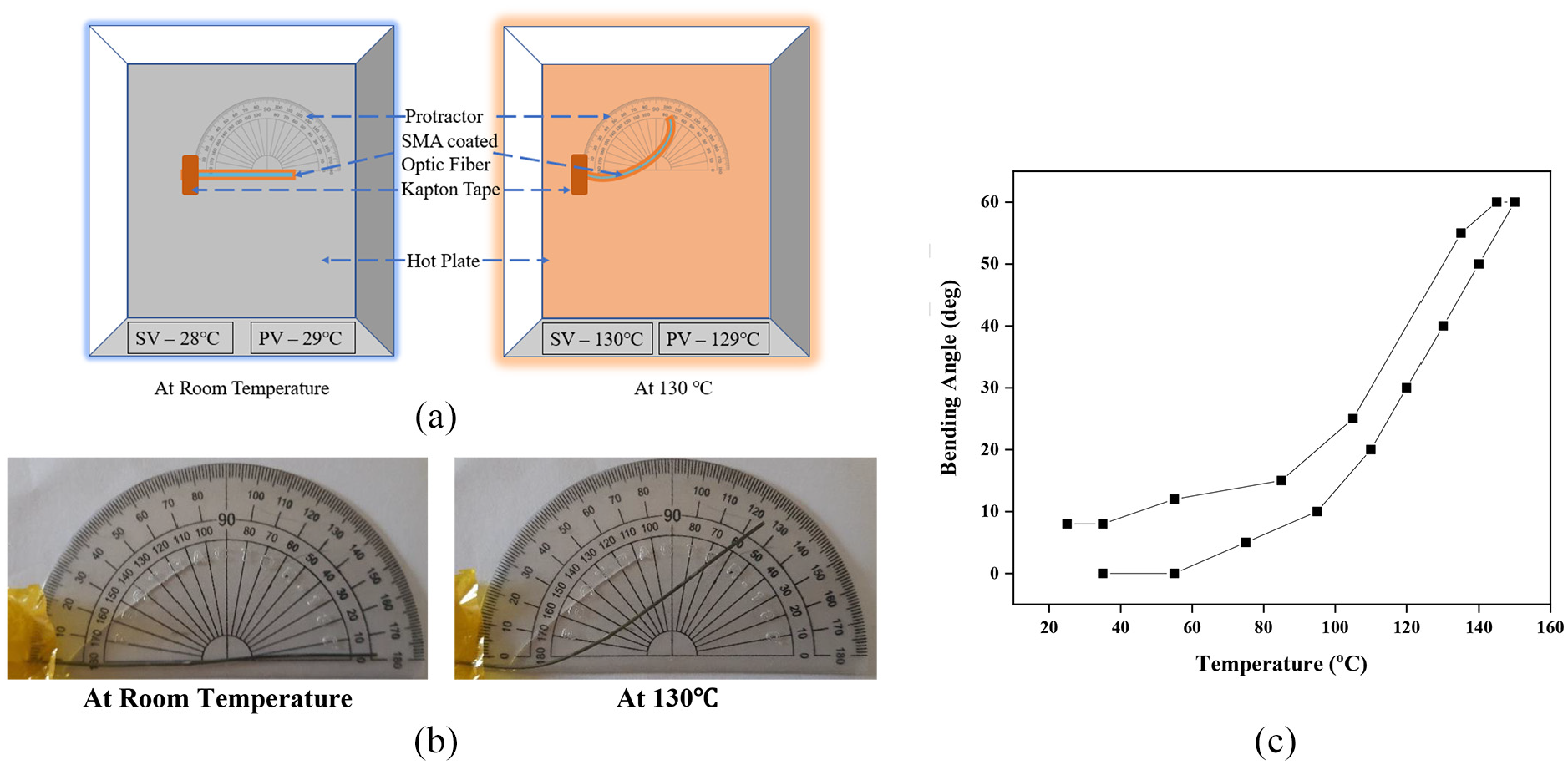
Shape recovery ratio measurement: (a) schematic of hot plate actuation, (b) experimental setup showing hotplate actuation, and (c) graph showing change in bending angle versus temperature.
3.7. Electrical actuation result
To study the life cycle characteristics of the SMA-coated optic fiber sensor, actuation studies were performed using Joule heating technique. Based on this resistive heating effect, the supplied electrical stimuli have been converted into thermal energy. An aluminum wire of diameter 0.05 mm has been used to surround the coated optic fiber for effective heat distribution over the fiber circumference during electrical actuation. The actuation of the SMA-coated optic fiber depends upon the specific heat of the SMA and the latent heat of transformation as due to its thermal properties and response. Aluminum wire has been chosen due to its lightweight and good electricity conduction capabilities. Here, the current is passing through the aluminum wire and only heat generated in the aluminum wire is transferred to the optical fiber. Here, an actuation setup platform was built and the optic fiber was placed with one end fixed at the clamp and the other end in a free moving manner with an ability to add varying loads. Thus, it consequently leads to varying displacement on the tip of optic fiber at the free end due to a thermo-elastic effect. A sequence of potential difference has been applied with varying voltage, current, and frequency for obtaining their actuation response and to study its dynamic displacement characteristics during real-time experimentation (Potapov and Da Silva, 2000; Saunders et al., 2016).
Different loads in the form of paper have been applied to the free end. In the initial stage, a load of 20 mg was applied but in this case actuation results were almost similar to no-load condition, when the load increased beyond 75 mg, then displacement range was very less. From all observations, load range was selected from 35 to 75 mg. The NiTi-coated fiber did not actuate at 1.5 V and coated fiber will get affected (separation of coating and substrate) after 3.5 V. Thus, the selected voltage of 2–3 V has been used for actuation. The amount of current which is drawn from the circuit depends on the resistivity of SMA.
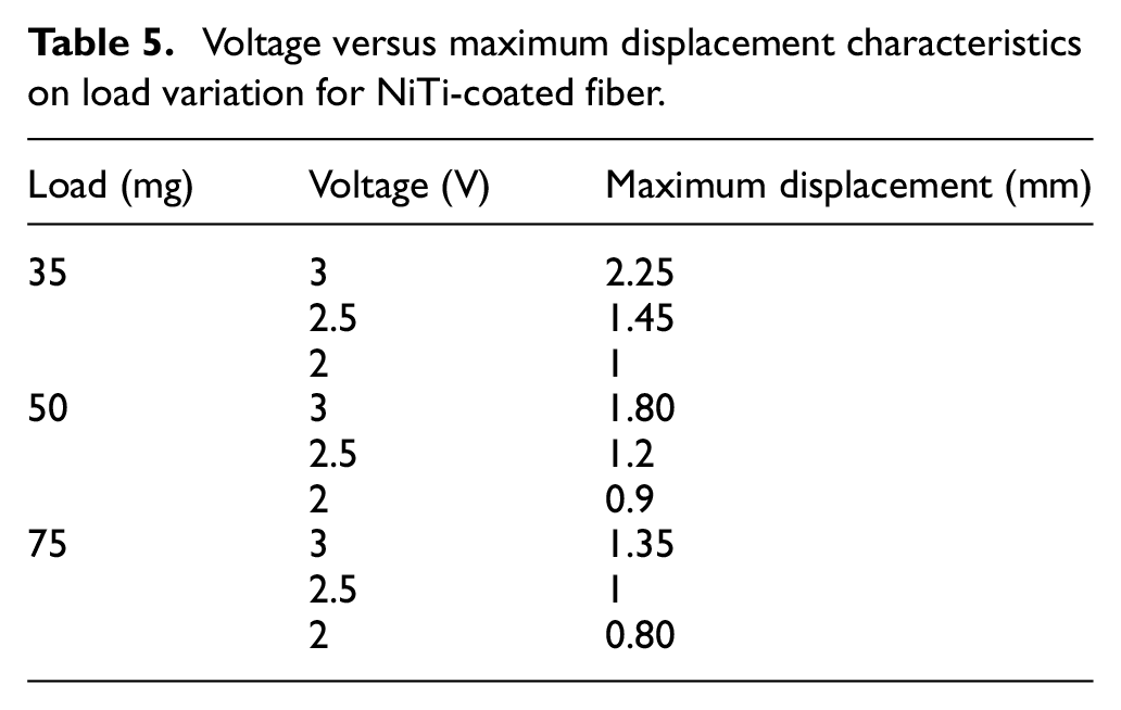
The thermomechanical test was conducted for NiTi-coated fiber under various conditions with changing loads of 35, 50, and 75 mg at different voltages of 2, 2.5, and 3 V and the results were mentioned in Table 5. NiTi-coated optical fiber actuates instantly, showing a higher sensitivity to Joule heating with faster kinetics of transformation as shown in Figure 10(a) to (c). With the increment of load, displacement is seen reduced because the load was resisting the moment during the experiment. The NiTi-coated optical fiber shows stable actuation with load increment. The life cycles of NiTi were analyzed using electrical actuation as shown in Figure 11. Figure 12 shows the actuation result up to 15,000 cycles which is showing reliability and fatigue life results of NiTi-coated fiber which is showing up to which cycle the fiber can actuate (Akash et al., 2018). The NiTi-coated fiber required up to 15,000 cycles to reach a displacement of 95% of the initial value after which coating got peeled off as shown in Figure 13. Life cycle test was performed for one sample at two different voltages. Thermal images were recorded during this test which is shown in Figure 14(a) and (b) with the help of Flir One thermal camera. For this semi-matte surface, selected surface emissivity was 0.8 (Akash et al., 2017a). Calculated sensitivity for NiTi-coated optical fiber was 0.016 mm/°C (Akash et al., 2017b). From this observation, it has been proved that SMA-coated fiber-based sensor can work in higher temperature. By performing this electrical actuation studies, it has been noticed that SMA-coated fiber-based sensor has shown maximum displacement of 2.25 mm. From the experimental specifications for 20 cm of fiber length, 200 mg fiber mass, and 75 mg load, the developed NiTi-coated optic fiber can actuate in force of more than 1 mN.
Voltage versus maximum displacement characteristics on load variation for NiTi-coated fiber.
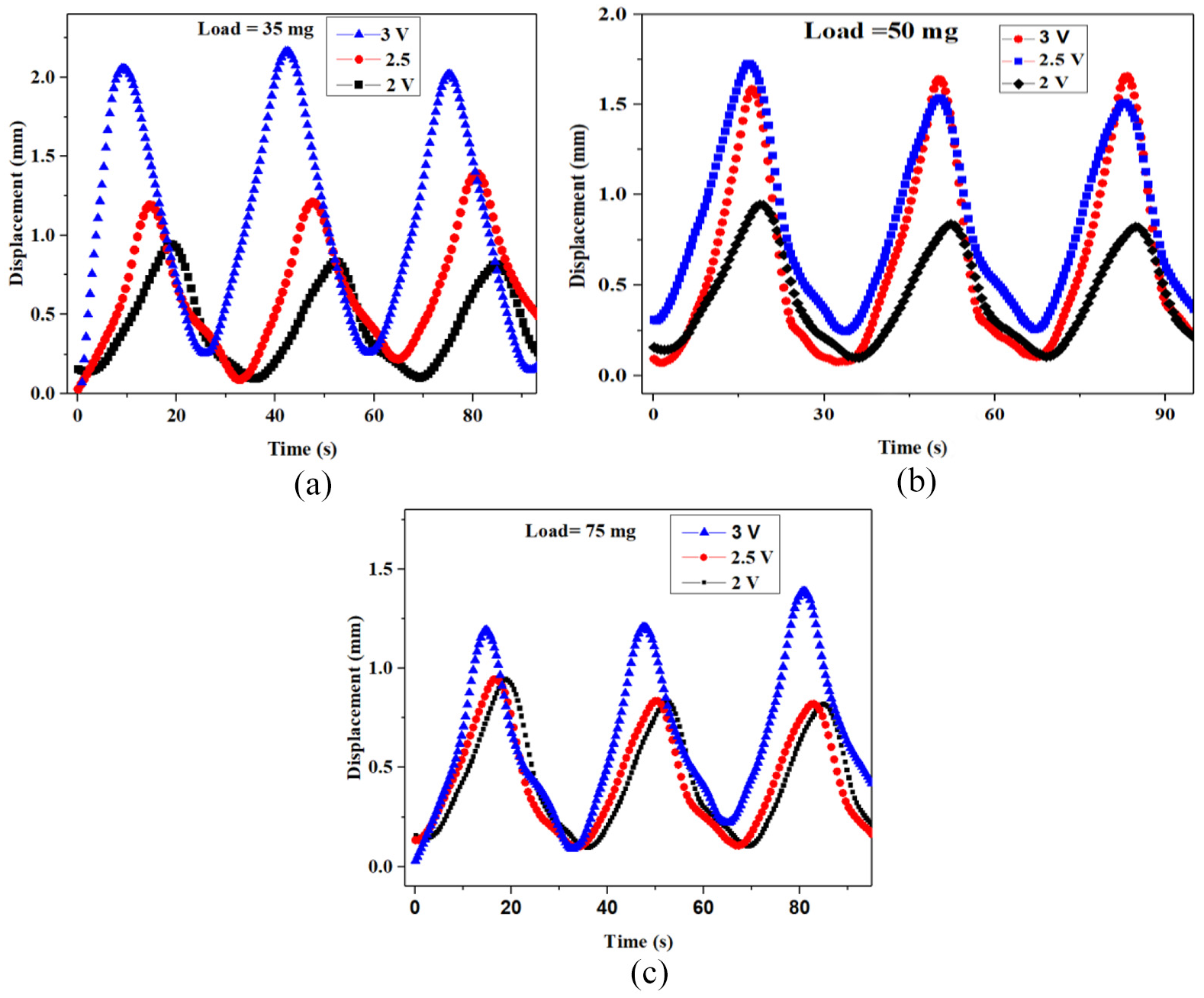
Actuation behavior of coated optic fiber with (a) 35 mg, (b) 50 mg, and (c) 75 mg at varying voltages.
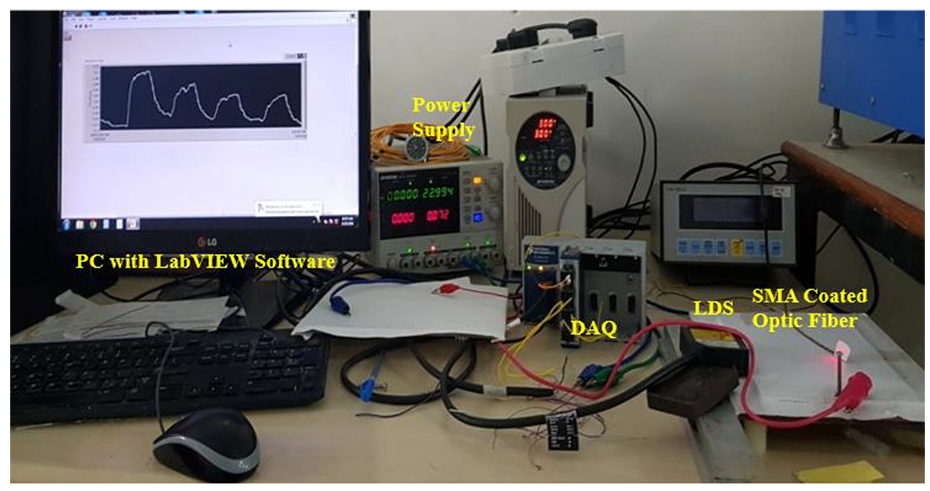
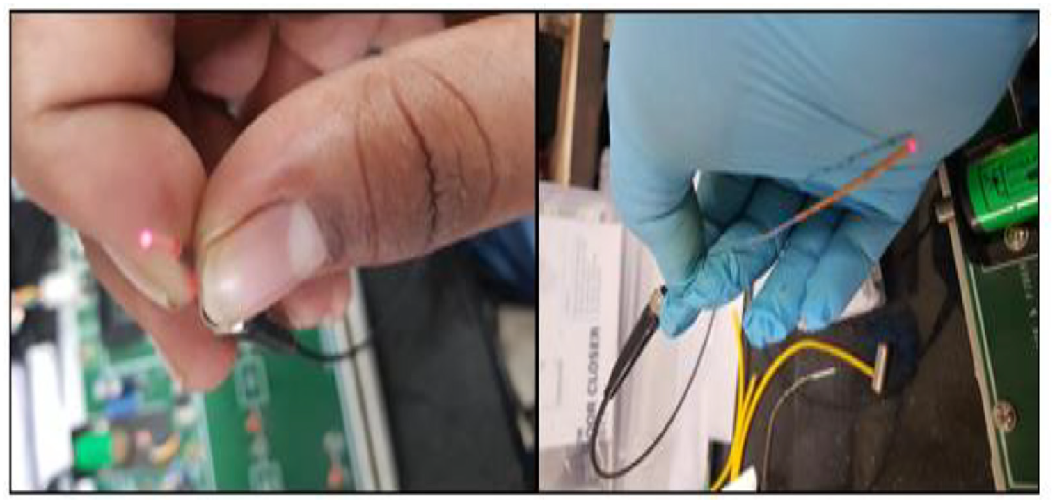
Experimental setup of life cycle analysis.
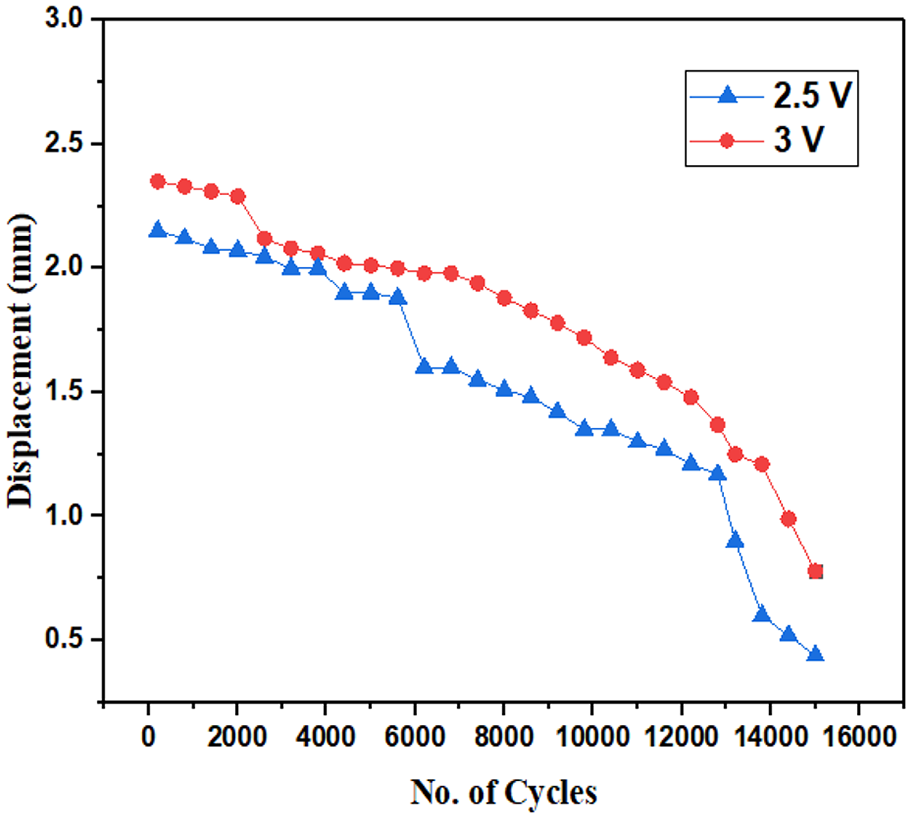
Life cycle behavior of NiTi-coated fiber up to 15,000 cycles.
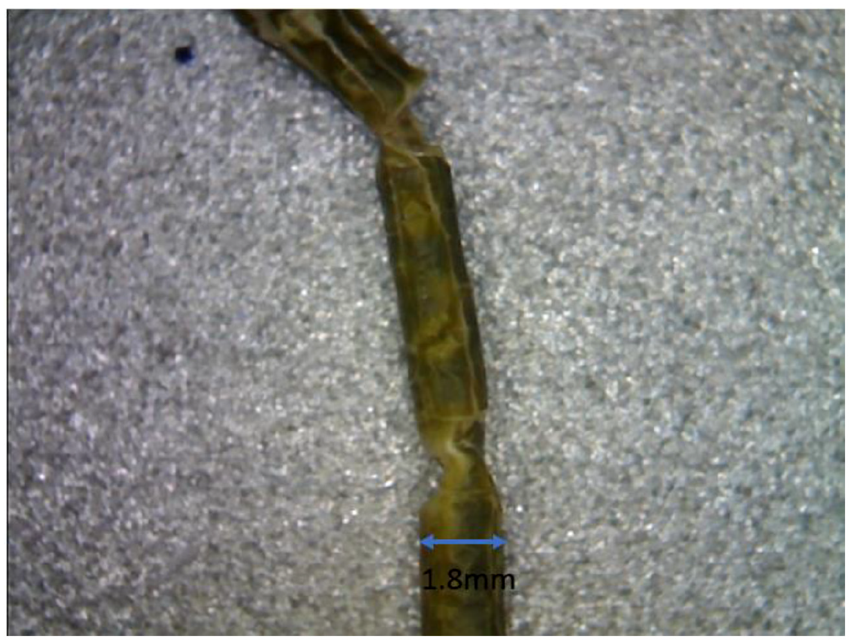
Sample after life cycle behavior.
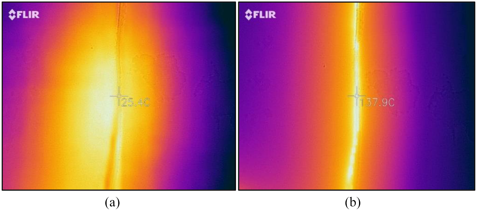
Thermal imaging of NiTi-coated optic fiber: (a) at the start of heating and (b) at the end of heating.
3.8. Sensing experimental results
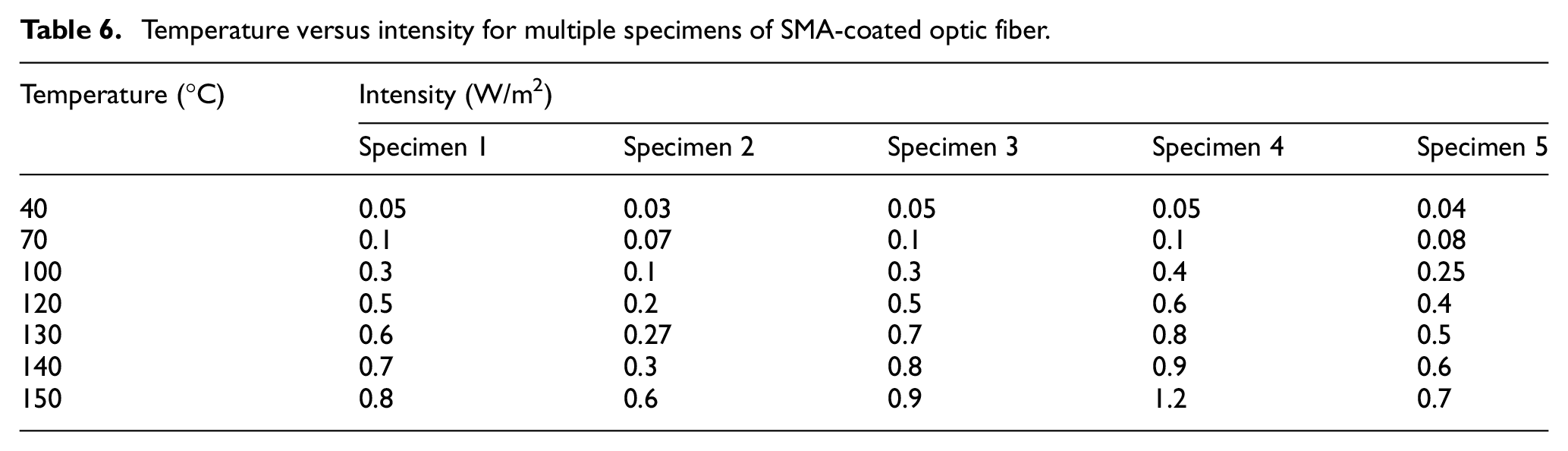
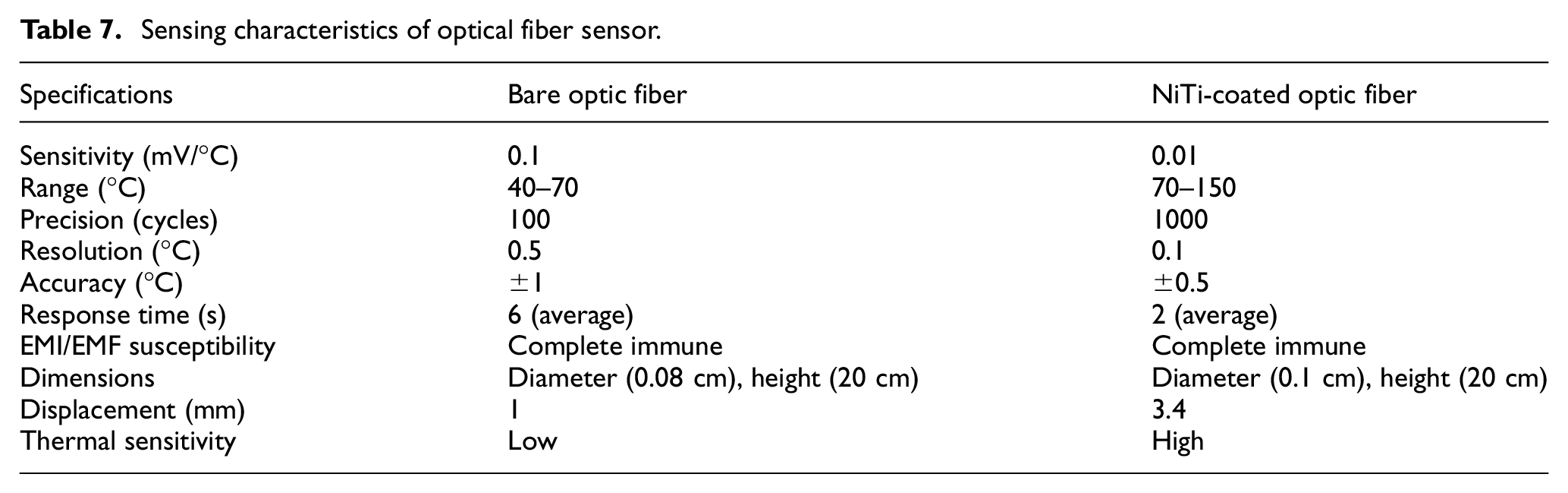
In this work, an experimental test bench was developed for evaluating the developed SMA-coated optic fiber samples. Heating coil made up of nichrome wire of 15 cm length and 0.50 cm coil diameter with 50 turns was used to generate heat around the optic fiber. The fiber was coupled at both the ends using three-dimensional (3D) printed coupling parts with the collimator and the pinhole detector. A 650-nm wavelength-based red-light emitting diode (LED) was used to generate light at the source side as shown in Figure 15. Also, a phototransistor (PT 333-3C everlight make) was used to measure the light intensity in terms of equivalent current at the output side. The results were observed for displacement (of optical fiber) versus intensity to study the response of the developed smart optic fiber sensor as mentioned in Figure 16. From the resulting graph mentioned in Figure 17(a) and (b) it has been observed that for increasing displacement in the SMA-coated optic fiber sensor, the light intensity varies and thus it affects photon energy with a subsequent increment in output current (Kidd, 1991). In case of bare fiber, the light intensity is higher whereas sensing temperature is very less but in the NiTi SMA-coated optic fiber, the intensity is moderate and also the temperature range of operation was double than that of bare one. Table 6 mentions the light intensity obtained from different test specimens and Figure 18(a) and (b) represents the error bar resulted from the standard deviation of five different specimens. For the NiTi-coated fiber-based sensor, sensitivity has been obtained as 0.01 mV/°C for variation in output deflection for change in input temperature of 1°C. The summary of the obtained sensing characteristics of the bare fiber and SMA-coated fiber has been mentioned in Table 7.
Light transmission via coated optic fiber.
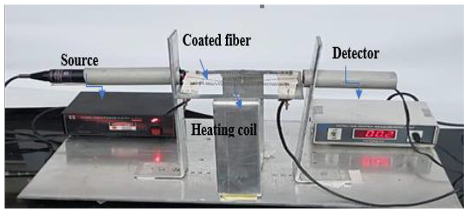
SMA-coated optic fiber sensing setup.
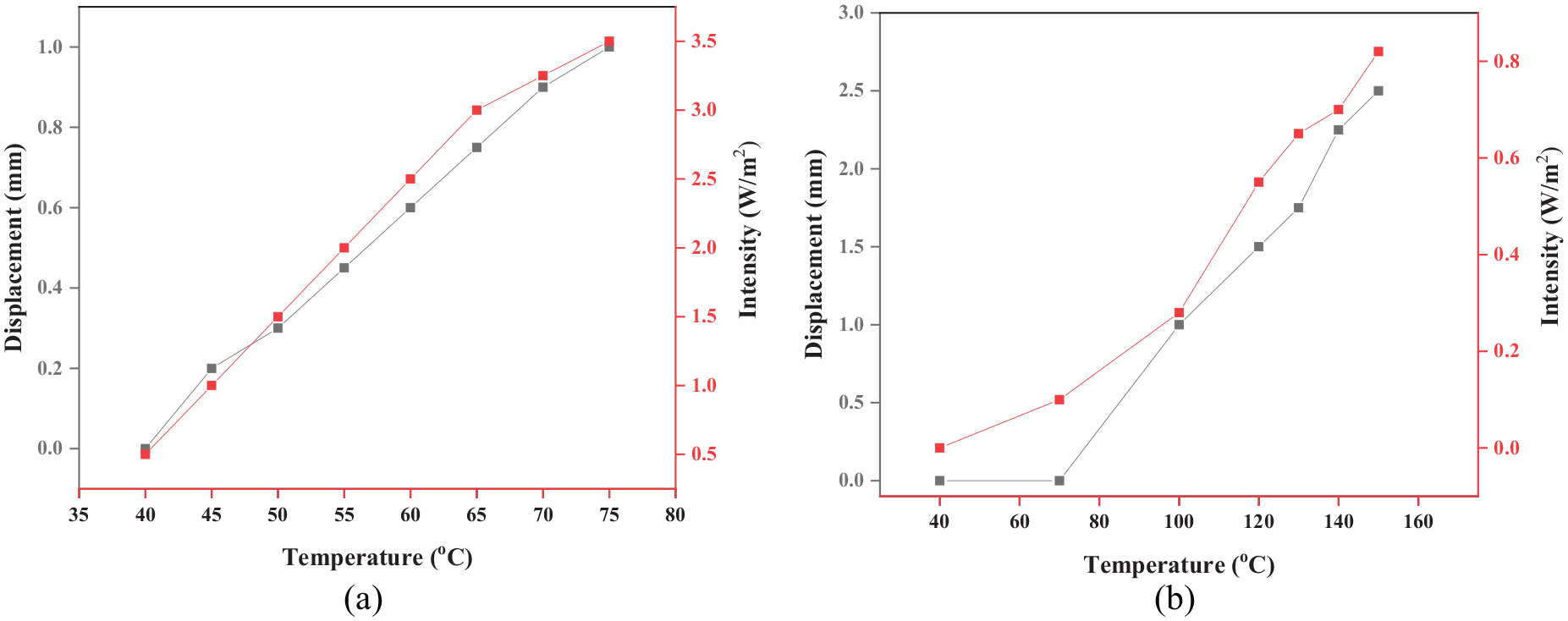
Displacement versus intensity graph on temperature scale for the (a) bare optic fiber and (b) NiTi SMA-coated optic fiber.
Temperature versus intensity for multiple specimens of SMA-coated optic fiber.
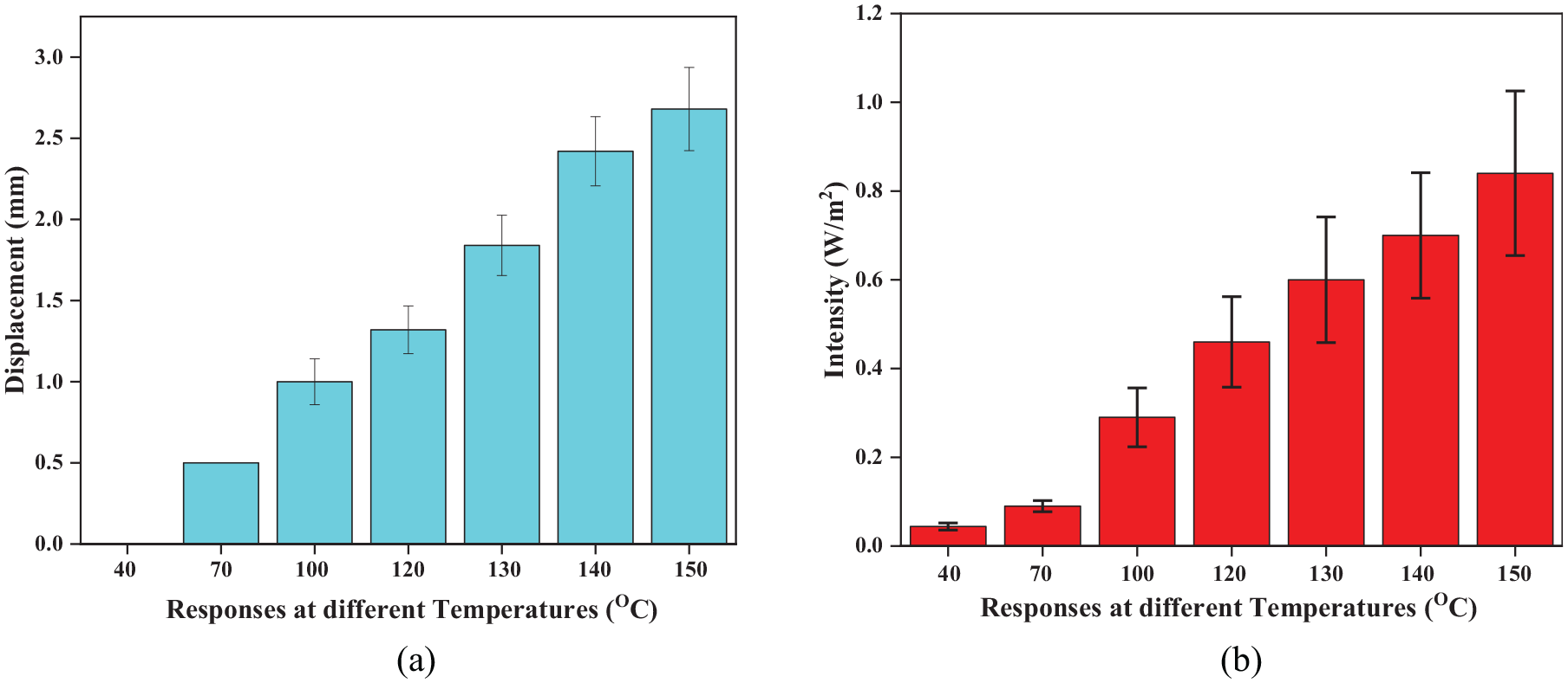
Error bar of NiTi SMA-coated optic fiber in temperature scale for (a) displacement and (b) intensity. Error bars are the standard deviations obtained from five different specimens.
Sensing characteristics of optical fiber sensor.
4. Light transmittance
Light transmittance is calculated as the fraction of incident light of a 650-nm wavelength which passes through the NiTi SMA-coated optic fiber. It has been calculated using the ratio of the transmitted intensity (I) to the initial intensity of the red light used (I0) (Chandra et al., 2007; Yoshidomi et al., 2015; Zhu et al., 2014)
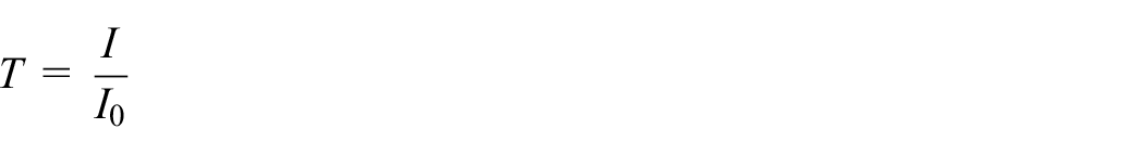
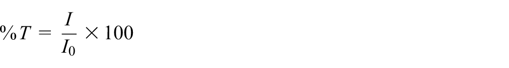
Thus, the transmittance is a numerical value that varies between zero, that is, when all light is absorbed, and one, that is, if no light is absorbed. Percent transmittance (%T) has been obtained by multiplying the factor by 100
Experiments were carried out to analyze the light transmittance effects in the NiTi SMA-coated fiber with the bare optic fiber. Even though the bare fiber makes better light transmittance of 90% up to 60°C, after 70°C the bare fiber started melting and at 90°C the fiber transmittance drops to zero due to the failure in the bare fiber thermal sensitivity. But in the case of NiTi-coated fiber, light transmittance was consistently increasing up to 130°C with improved SMA micromechanic structure over the fiber surface as mentioned in Figure 19. On comparing, maximum light transmittance of SMA-coated optical fibre lags by 10% which arises due to the effect of flash evaporated materials over the optical fiber circumference, where the formed interface layer in between SMA and optic fiber surface in the coated one gets reduced diameter than the bare fiber.
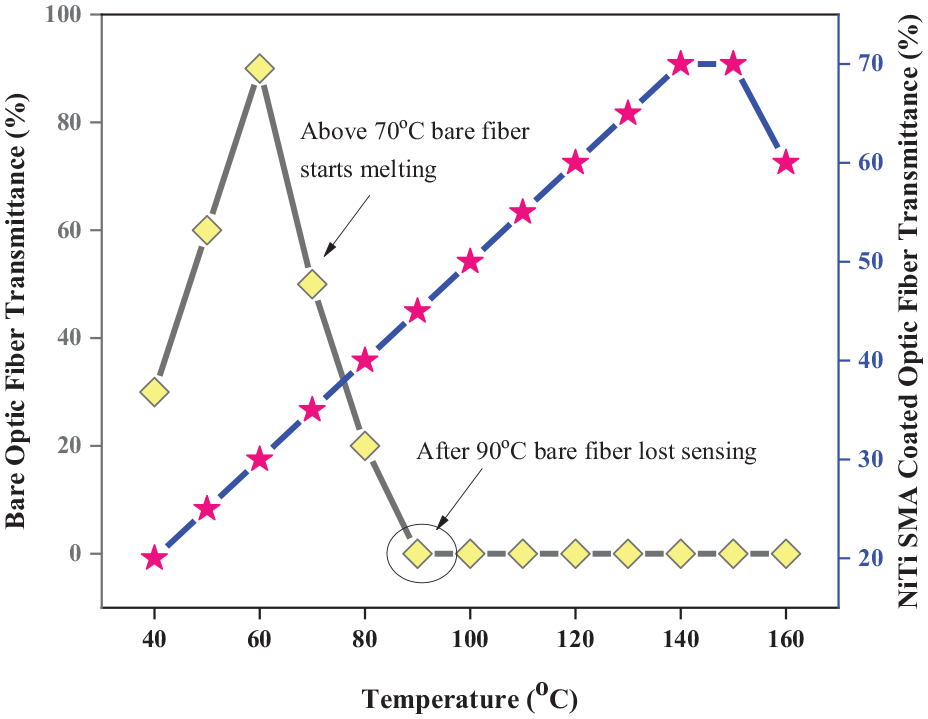
Light transmittance of the bare fiber and SMA-coated optic fiber.
5. Conclusion
From the above experimental results, it can be accomplished that NiTi-coated optical fiber developed through flash evaporation showed cyclic periodicity.
The results are encapsulated as the following
From the SEM results, the surface morphology of the coated optical fiber is continuous, smooth, and has layered surface with a grain size of approximately 330 nm.
The fiber coated with NiTi exhibits monoclinic structure in the martensite phase, rhombohedral structure in the R phase, and cubic structure in the austenite phase. Due to the presence of the R phase, the two-way shape memory effect is enhanced in NiTi.
From the DSC examination, the austenite change temperature for NiTi was observed to be 122.3°C and martensite-start begin temperature was 113.0°C.
The developed sensor can sense the temperature in the range of 70°C to 130°C.
The cyclic behavior was studied using an electrical actuation. NiTi took less time to actuate and also showed a maximum displacement of 2.25 mm.
Calculated sensitivity for NiTi-coated fiber-based sensor is 0.01 mV/°C.
The developed SMA-coated optic fiber can actuate in force of more than 1 mN.
NiTi SMA-coated optic fiber showed better light transmittance at higher temperature range than the bare optic fiber.
Compared with the conventional metallic coating, the advantages of NiTi-coated optic fiber signal have been evaluated in the work. The optical signal has been coupled with phase transformation temperatures of the NiTi SMA. At each of the four phases, a drastic change occurs in the optical signal. These can be noted from austenite–martensite reverse and forward transformation temperatures toward sense. Using this thermally sensitive material (i.e. SMA) with the boon of varying alloy composition, the sensing range can be varied by altering the switching temperature over a wider region (−200°C to 200°C) which cannot be realized using a conventional metallic coating.
Disadvantages of this sensor technology include higher manufacturing cost than a conventional metallic coating, lack of trained expertise, and skilled personnel’s in SMA technology. Coating using flash evaporation reduces optical transmittance which can be improved using other manufacturing technologies (i.e. sputtering). Also, using Cu-based alloy coating and other alloy increases the sensing properties and temperature range can be improved significantly.
Footnotes
Acknowledgements
The authors thank Sophisticated Instrumentation Center of IIT Indore for their support in providing characterization facilities. The authors also thank all the researchers of Mechatronics and Instrumentation lab for their suggestions and help during experiments.
Declaration of conflicting interests
The author(s) declared no potential conflicts of interest with respect to the research, authorship, and/or publication of this article.
Funding
The author(s) disclosed receipt of the following financial support for the research, authorship, and/or publication of this article: S.S. gratefully acknowledges the financial aid support received from the Ministry of Human Resource and Development. K.S. gratefully acknowledges the financial aid support received from the Council of Scientific and Industrial Research (CSIR) Human Resource Development Group (Extra Mural Research Division-I), Ministry of Science and Technology, Government of India, through the project grant (CSIR Project Sanction No. 09/1022(0032)/2016-EMR-I Acknowledgment Number: 181408/2K15/1) for carrying out this work.