





Abstract
In this article, a magnetorheological elastomer peristaltic pump capable of bidirectionally conveying Newtonian and non-Newtonian fluids with precise net pumped volume and required viscosity patterns of fluids is presented and numerically investigated. The basic element is very succinct, which is composed of only a magnetorheological elastomer tube and an electromagnet. Two basic elements in series constitute a magnetorheological elastomer peristaltic pump. The maximum pumped volume can be achieved using maximum lag between voltage parameters gap1 and gap2. The Nelder–Mead optimization method is applied to realize the precise control of the net pumped volume during a steady working cycle. For a certain net pumped volume, the viscosity of fluids can also be adjusted through the modulation of the driving voltage parameters obtained from the Nelder–Mead optimization method.
1. Introduction
Magnetorheological elastomers capable of remotely controlled deformation under an external magnetic field have attracted increasing attention in the field of smart materials (An et al., 2012; Chen et al., 2007; Chen et al., 2008; Cheng et al., 2010; Carlson and Jolly, 2001; Davis, 1999; Galipeau and Castaneda, 2012; Ginder and Davis, 1994; Gong et al., 2012; Huang et al., 2019; Oliveira et al., 2017; Rabinow, 1948; Shah et al., 2014; Xu et al., 2011; Xu et al., 2019). MREs where magnetic particles are embedded into an elastomer matrix are widely applied in vibration absorbers (Sun et al., 2015), smart vibration isolation systems (Oliveira et al., 2017; Khoo and Liu, 2001; Song et al., 2016), soft microrobots (Diller et al., 2014; Hu et al., 2018; Lum et al., 2016; Sitti, 2018; Xu et al., 2019), and so on. This characteristic is also utilized in sensitive liquid conveying, especially drugs and biofluids (Fuhrer et al., 2013; Kutev et al., 2015). The magnetorheological elastomer peristaltic pump (MRE-PP) without any moving parts is first presented by Fuhrer, and related scheduling policies of electromagnets are also investigated to restrain backflow (Fuhrer et al., 2013). The device without batteries can be in vivo used, allowing less harm to human bodies compared to classic pumps such as artificial heart pumps with battery (Hu et al., 2018). MRE-PPs with valves are numerically investigated by Behrooz and Gordaninejad (2016a, 2016b), which can only unidirectionally convey Newtonian fluids. In the study, net pumped volume can be modulated by adjusting the magnitude of the magnetic field. The conceptual design of MRE-PP similar with two-dimensional (2D) design from Gordaninejad has more simple structure, which is proposed by Ehsani and Nejat (2017).
The above-mentioned MRE-PPs and other micro-fluid transport systems (Liu et al., 2017; Said et al., 2017; Stork and Mayer, 2018; Yamahata et al., 2005) actuated by a magnetic field have only one actuator, which causes the viscosity to be dependent on net pumped volume. For a certain value of net pumped volume, the pattern of viscosity cannot be adjusted using the aforementioned MRE fluid transport systems. Besides, the bidirectional conveying of fluids cannot be achieved in these devices. The precise net pumped volume is also not obtained easily, although it is necessary in many engineering fields (Barnoon and Toghraie, 2018; Kutev et al., 2015; Ma et al., 2017; Oka et al., 2005; Taitel and Dukler, 1976; Tao et al., 2016; Vasilyeva, 2017). In the previous study, we presented a 2D smart MRE-PP to convey water and blood bidirectionally (Wu et al., 2019a) and a three-dimensional (3D) MRE-PP with an analogic moisture loss process (Wu et al., 2019b). The MRE-PP has a great potential to convey fluids precisely while controlling fluid viscosity. However, this precise control of the MRE-PP has not been reported yet.
In this study, we numerically investigate an MRE-PP which consists of two basic elements in series. Each basic element is composed of an MRE tube and an electromagnet which consists of a coil and an iron core. Silica-coated carbonyl iron particles–filled silicone vulcanizates, whose magnetic property is characterized by a magnetization curve, are selected as the MRE material, which allows desired time-dependent shapes through the modulation of control parameters of the magnetic field (Poojary and Gangadharan, 2016). The required net pumped volume and the fluid viscosity can be achieved by the control parameters obtained from the Nelder–Mead optimization method.
2. 2D models of MRE-PPs
2.1. Constitutive equation
In the numerical study, the magneto-fluid–solid interaction (MFSI) should be elucidated first. The magnetization curve (Wu et al., 2017; 2019a; 2019b) and Mooney–Rivlin model (Sun et al., 2014; Yang et al., 2017; Yu and Zhao, 2009) are utilized to represent magnetic-induced body force, and the equilibrium and constitutive equations of a mass point in MRE domain are written as follows
where
where p is the pressure in the fluid domain,
where
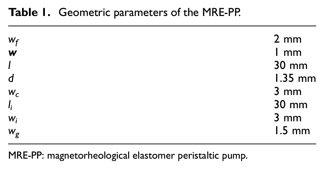
Finite element method (FEM) simulation and the built-in Nelder–Mead optimization method are performed using COMSOL Multiphysics for solving MFSI and obtaining control parameters of the driving voltage. 2D simulation of MRE-PPs is utilized to analyze their performance, adopting plane strain assumption. Rectangles with various sizes are employed to represent the basic element domain composed of an MRE tube domain, fluid domain, and an electromagnet domain, as schematically illustrated in Figure 1(a). Two elements in series constitute an MRE-PP, as shown in Figure 1(b). The geometric parameters are illustrated in Table 1. Finite element mesh of the MRE-PP is depicted in Figure 1(c). The magnetic properties of the MRE tubes are the same with our previous study (Wu et al., 2019a), which is imported in COMSOL using interpolation function, as illustrated in Figure 1(d). Joint parts of neighboring MRE tubes are fixed by clamps with 2-mm width, and two ends of MRE-PPs are fastened. Open boundaries are applied to both inlet and outlet. The function of the constant of 20 V, multiplied by the square wave function with the low and high levels of 0.01 and 1.01, is applied as the driving voltage on the electromagnets. The pattern of square wave function can be tuned through the modulation of two parameters (gap1, gap2) for the MRE-PP, which determines the pattern of the external magnetic field, as illustrated in Figure 2(a). Several identical square wave functions in series allow for continuous working of the MRE-PP, as shown in Figure 2(b). Compared with the modification of geometric variables, the scheduling strategy of the two electromagnets determined by parameters gap1 and gap2 can be tuned in a more flexible and real-time way during the process of fluid conveying.

(a) Sketch of the basic element of MRE-PPs; (b) sketch of MRE-PP composed of two basic elements in series; (c) finite element mesh of the MRE-PP; and (d) magnetic properties of the MRE tubes identical with our previous study (Wu et al., 2019a).
Geometric parameters of the MRE-PP.
MRE-PP: magnetorheological elastomer peristaltic pump.

Square wave functions (a) with gap1 and gap2 for two-element MRE-PP and (b) with the period of 0.4 s.
2.2. Optimization method
The maximum and required net pumped volumes depend on the deformation of MRE tubes upon the external magnetic field during a steady working cycle. Consequently, these parameters can be utilized to obtain the required net pumped volume. However, the process is too complicated to obtain the succinct relationship between control parameters and net pumped volume over a steady working cycle. The Nelder–Mead optimization method is applied to obtain the corresponding parameters for the required net pumped volume during a steady working cycle (Chelouah and Patrick, 2003; Gao and Han, 2012; Lagarias et al., 1998; Luersen and Le, 2004; Olsson and Nelson, 1975).
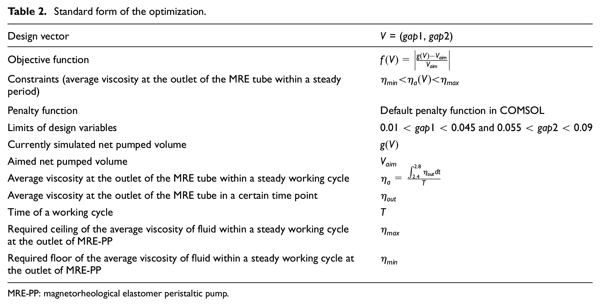
The method maintains a nondegenerate simplex and an n-dimensional geometric figure that is the convex hull of (n + 1) vertices at each step to complete the iterative solution of optimization parameters (Olsson and Nelson, 1975). Each iteration starts at a simplex defined by its (n + 1) vertices and the related function values. After the computation of two or more test points along with their function values, the iteration terminates when a new simplex allows the function values at its vertices meeting some requirements in descent condition in comparison with the previous simplex (Gao and Han, 2012). The iterative process is repeated until the simplex converges to the minimum of the function. In this simulation, two parameters gap1 and gap2 are tuned, thus n is equal to 2 and the simplex is a triangle. The gaits of Nelder–Mead optimization are sketchily illustrated in Supplemental Figure S1, including the operation of reflection, expansion, outside contraction, inside contraction, and shrink. In the Nelder–Mead optimization process, for the required net pumped volume, the design vector, objective function, constraints, and the limits of design variables are expressed as shown in Table 2. In the optimization process, f(V) is minimized through the modulation procedure of the parameters of gap1 and gap2. Time of a working cycle T is set as 0.4 s.
Standard form of the optimization.
MRE-PP: magnetorheological elastomer peristaltic pump.
Only in the control of fluid viscosity pattern, constraints and default penalty function in COMSOL are applied. For shear thickening and thinning fluid, only
3. Results
3.1. Maximum net pumped volume
The time lag between two electromagnets utilized by the lag between gap1 and gap2 renders asymmetric magnetic field and asymmetric fluid field, thus obtaining non-zero net pumped volume. The parameter sweeps of gap1 and gap2 are performed to obtain the maximum net pumped volumes for the Newtonian, shear thickening, and shear thinning fluids in the MRE-PP, as illustrated in Figure 3. The impact of control parameters on the net pumped volume is varied for various fluids.

Net pumped volume of Newtonian (square), shear thickening (sphere), and thinning (triangle) fluids in the MRE-PP with various control parameters gap1 and gap2.
The net pumped volume of the Newtonian and shear thickening fluids is positive when the value of gap1 is lower than that of gap2, while the shear thinning fluid shows the opposite performance. The more obvious difference between gap1 and gap2 can render greater net pumped volume for all fluids. The maximum net pumped volume appears at gap1 = 0.01 s and gap2 = 0.09 s for the Newtonian and shear thickening fluids, and at gap1 = 0.09 s and gap2 = 0.01 s for the shear thinning fluid.
3.2. Required net pumped volume
Besides the realization of maximizing fluid conveying in the MRE-PP, the required net pumped volume and corresponding control parameters of actuation inputs are more important in biological and medical industry. The Nelder–Mead optimization is applied to solve this issue. The required net pumped volumes of 2.72 × 10⁻⁸ m3 are conducted to verify the corresponding feasibility of the Nelder–Mead optimization method. The ranges of gap1 and gap2 are varied with fluids, allowing the acceleration of convergence, as shown in Supplemental Table S2. For shear thickening fluid, initial triangle is constructed by three vertexes of (gap1, gap2) = (0.04, 0.06), (gap1, gap2) = (0.01, 0.06), and (gap1, gap2) = (0.04, 0.09), and f at the corresponding vertexes is first computed. Then, the optimization operation is conducted. The initial and final optimization procedures of the shear thickening fluid are plotted in Figure 4(a) and (b), respectively.

The Nelder–Mead optimization procedure for shear thickening (a, b), shear thinning (c, d), and Newtonian fluids (e, f), at initial (a, c, e) and final (b, d, f) steps.
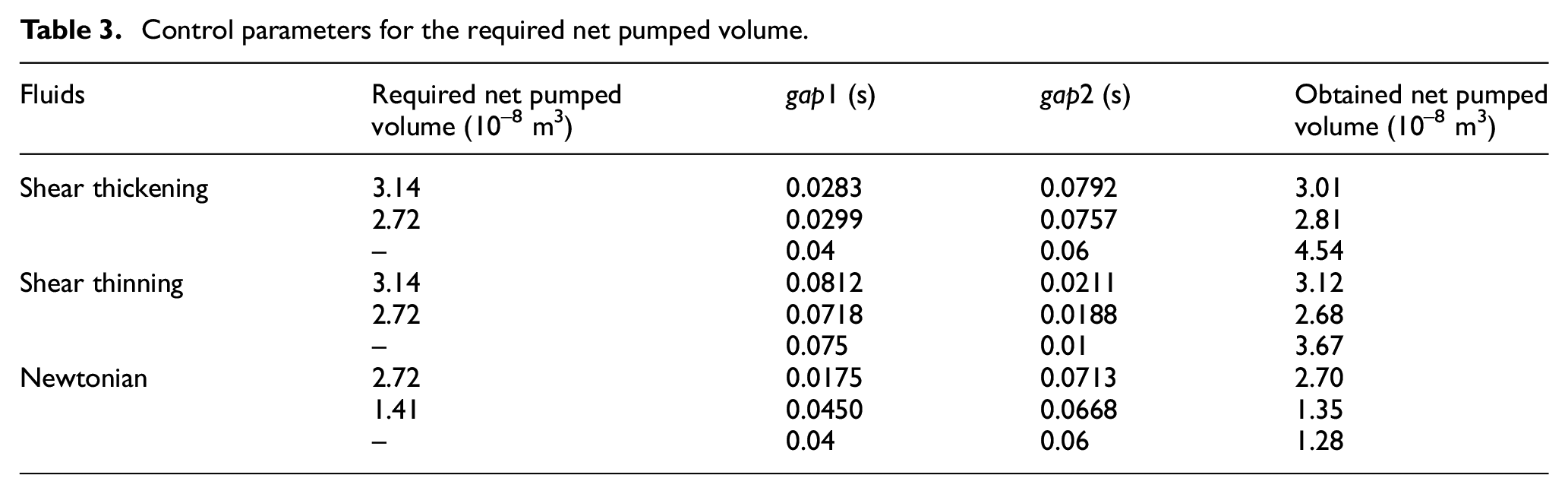
The Nelder–Mead optimization method also utilizes the same operations including reflection, expansion, outside contraction, inside contraction, and shrink to obtain gap1 and gap2 for the required net pumped volume of shear thinning and Newtonian fluids, as shown in Figure 4(c)–(f), respectively. With limits of parameters (Supplemental Table S2), some operations cannot be performed. For instance, the inside constriction is applied instead of reflection for the worst point at (gap1, gap2) = (0.01, 0.075) in shear thinning fluid conveying. The values of gap1 and gap2 generating other required net pumped volume can also be obtained through the modulation of Vaim. All results are shown in Table 3. The maximum discrepancy between the required and the obtained net pumped volume is 4.2% (in shear thickening fluid), demonstrating that the control parameters gap1 and gap2 for the required net pumped volume can be obtained through the Nelder–Mead optimization. We also list g(V) at several initial points in Table 3. The huge discrepancy between g(V) and Vaim could be found, which is also shown in terms of f(V) in Figure 4. Comparing the initial g(V) and final g(V), it could be seen that the solution has been significantly improved, further demonstrating the validation of the Nelder–Mead optimization method.
Control parameters for the required net pumped volume.
In order to investigate the working pattern in detail, the outflow of Newtonian, shear thickening, and shear thinning fluids is shown in Figure 5. In shear thinning fluid conveying, obvious fluctuation appears, resulting in more efflux and backflow. However, the feeble fluctuation is observed in shear thickening fluid conveying. The interaction between the MRE tube and the fluids is non-instantaneous, due to the intermediate Reynolds number (Re is calculated in Supplemental Figure S3). The net pumped volume is the integral of the outflow. Hence, the varied outflow pattern can lead to the similar net pumped volume.

Outflow of the Newtonian, shear thickening, and thinning fluids with the net pumped volume of 2.72 × 10⁻⁸ m3 during a steady working cycle in the MRE-PP.
3.3. Control mechanism
The magnetization and the deformation of the MRE tube, and the magnetic flux density of iron core, are monitored to further reveal control mechanism, as shown in Figure 6. The control parameters gap1 and gap2 determine the magnetic flux density of iron cores, allowing the magnetization of the MRE tube and then the bend of the corresponding MRE tube. The magnetization and deformation of the MRE tube for shear thickening, shear thinning, and Newtonian fluids at the same time point are varied, due to different values of gap1 and gap2. However, the relationship between the control parameters and the net pumped volume is not analytical. Hence, the simulation and the optimization method, named the Nelder–Mead optimization method, provides a novel path for fluid control. The identical deformations of the MRE tube at 2.4 and 2.8 s are observed, demonstrating steady working status of the MRE-PP.

Magnetization and deformation of the MRE tube, and magnetic flux density of iron core for (a)–(e) shear thickening, (f)–(j) shear thinning, and (k)–(o) Newtonian fluids at varied time points. The deformation of the MRE tube is amplified for clear display. The black frame plots the original geometry of the MRE-PP.
3.4. Magneto-fluid–solid interaction
The fluid pressure, body force generated by magnetic field, and deflections of MRE in y-axis for shear thickening fluid at several time points are monitored for the qualitative assessment of the full couple among magnetic field, structure field, and fluid field, as plotted in Figure 7. The fluid pressure, fluid viscosity, and magnet-induced body force in y-axis are varied with driving voltage determined by control parameters gap1 and gap2, and the former one in turn affecting the deflections of MRE in y-axis. When the electromagnet works, the obvious magnet-induced body force is loaded on the nearby part of the MRE tube. The top part of the MRE tube is deflected and the fixed bottom part of the MRE tube is not.

Fluid pressure, body force generated by magnetic field in y-axis, fluid viscosity, and deflections of MRE in y-axis for shear thickening fluid at (a) 2.4 s, (b) 2.5 s, (c) 2.6 s, and (d) 2.7 s. The latter two are shifted by 15 mm along the vertical axis for clear display.
3.5. Required average viscosity at the outlet of MRE-PP within a steady working cycle
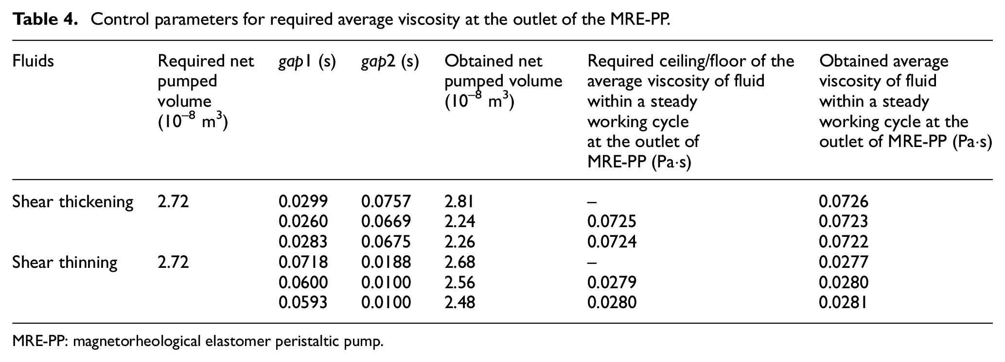
The viscosity of fluids extremely affects the physical, chemical, and biological properties of non-Newtonian fluid (Kutev et al., 2015; Oka et al., 2005). Previous studies adjust the viscosity pattern with obvious change in the net pumped volume. In this study, the net pumped volume is nearly maintained, while the average viscosities at the outlet of the MRE tube within a steady working cycle are tuned. The viscosities of the shear thickening and thinning fluids with constant required net pumped volume of 2.72 ×10⁻⁸ m3, respectively, are shrunk and enhanced. The detailed information is shown in Table 4.
Control parameters for required average viscosity at the outlet of the MRE-PP.
MRE-PP: magnetorheological elastomer peristaltic pump.

Average viscosity of the (a) shear thickening and (b) thinning fluids with the net pumped volume of 2.72 × 10⁻⁸ m3 during a steady working cycle in the MRE-PP under restricted conditions.
4. Conclusion
In this article, an MRE-PP capable of precisely conveying Newtonian, shear thickening, and shear thinning fluids is presented, compared with other MRE-PPs with rough and imprecise fluid-conveying capability. The maximum net pumped volumes are realized through the greatest difference between gap1 and gap2 values. The Nelder–Mead optimization method is appropriate to reversely obtain the control parameters with the required net pumped volume, due to the non-analytic relationship between them. More importantly, the modulations in viscosity pattern of the fluids are also realized with nearly no variation in the net pumped volume using the same optimization method with constrain and default penalty function. We envision that the inverse MRE-PP design with optimization method could enable a much broader scope of optimal designs and data-driven control algorithms that goes beyond MRE devices with intelligence.
Supplemental Material
Supplementary_material-7 – Supplemental material for Magnetorheological elastomer peristaltic pump capable of flow and viscosity control
Supplemental material, Supplementary_material-7 for Magnetorheological elastomer peristaltic pump capable of flow and viscosity control by Chenjun Wu, Xinpeng Fan, Qingxu Zhang, Wei Wang, Yihu Song and Qiang Zheng in Journal of Intelligent Material Systems and Structures
Footnotes
Acknowledgements
Chenjun Wu thanks Xianwen Guo (Peking University) and Yuhai Xiang (Zhejiang University) for discussion on computed fluid dynamics and computational mechanics. Chenjun Wu also thanks Hanyu Wang (Wuhan University of Technology), Yunhui Wang (Huawei Technologies Co., Ltd.), and Zhengxiong Wang (Shanghai Jiao Tong University) for the discussion on the optimization method.
Declaration of conflicting interests
The author(s) declared no potential conflicts of interest with respect to the research, authorship, and/or publication of this article.
Funding
The author(s) disclosed receipt of the following financial support for the research, authorship, and/or publication of this article: This work was supported by the National Natural Science Foundation of China (Grant Nos 51873190, 51790503, and 51573157) and Natural Science Foundation of Shandong Province (Grant No. ZR2018MEM022).

Supplemental material
Supplemental material for this article is available online.
References
Supplementary Material
Please find the following supplemental material available below.
For Open Access articles published under a Creative Commons License, all supplemental material carries the same license as the article it is associated with.
For non-Open Access articles published, all supplemental material carries a non-exclusive license, and permission requests for re-use of supplemental material or any part of supplemental material shall be sent directly to the copyright owner as specified in the copyright notice associated with the article.
