
Abstract
In this article, a novel bi-directional shear mode magneto-rheological elastomer–based vibration isolator has been designed, fabricated, and characterized to improve the dynamic response and identification of this class of “intellectual” mechanical devices. A heuristic embodiment has been realized in order to design such an isolator wherein both the vertical and horizontal directions can be operated only in the shear mode not only individually but also simultaneously. Two fixtures have been designed for performing the characterization of the magneto-mechanical behavior of the proposed magneto-rheological elastomer isolator in the vertical and horizontal shear modes under wide ranges of strain amplitude (4%–32%), excitation frequency (1–8 Hz), and magnetic flux density (0–220 mT). Experimental results revealed maximum relative magneto-rheological effects of 35% and 27 % in the vertical and horizontal shear modes, respectively. Furthermore, basic mathematical models of single-degree-of-freedom systems, employing the magneto-rheological elastomer–based isolator in the vertical and horizontal shear modes, have been established. The proposed magneto-rheological elastomer isolator in the vertical mode exhibited natural frequency shift of 6.1% by a small increment in the magnetic flux density which approves the potential of the proposed bi-directional shear mode magneto-rheological elastomer–based vibration isolator for vibration control applications, such as seat suspension systems.
1. Introduction
Many mechanical systems are daily in an expose of vibration from low to high frequency which can result in fatigue failure. Likewise, vibration, even in short period or low strength, can severely affect the performance of many sensitive electrical and optical instruments such as laser measurement systems, fiber sensing devices, and structural health monitoring equipment. Moreover, civil structures such as buildings, bridges, highways, traffic signals, and variable-message signs are susceptible to environmental stimulus such as wind, rain, vortex induced vibration (VIV), earthquakes, and storms, which enforce several levels of displacement and acceleration demands (Meyer et al., 2015; Yarra et al., 2018; Zhao et al., 2017). Furthermore, many human beings, according to their environmental work space, are at risk of excessive vibration which can lead to serious diseases such as hand-arm vibration syndrome (HAVS) (Yao et al., 2018), chronic back pain, spinal misalignment, and neck strain (Castelo et al., 1999). One practical solution is, indeed, employing vibration isolation technique to attenuate shock and vibration which induced failure and injury in mechanical systems and human being, respectively. Many vibration isolation techniques and devices have been developed that can be categorized into main three groups such as passive, active, and semi-active systems. Passive systems have already been employed for vibration reduction applications; however, they operate in a very limited bandwidth around the designated tuned frequencies. Another approach is to utilize active systems which, besides the passive elements, contain an actuator which applies a control force following an appropriate control law so as to guarantee adjusting to any value of vibration attenuation within a frequency bandwidth. Active systems, however, require large amount of power and may lead to instability of systems in case of control malfunction. Semi-active (adjustable) vibration isolators have been widely accepted for vibration attenuation applications due to their frequency shift capability. The semi-active strategy is nearly identical to that of a conventional passive system with the exception that the semi-active technique consists of a variable coefficient of stiffness/damping, which can be adapted in real time according to different requirements. The semi-active vibration isolation systems have received numerous attentions since they waste less power consumption than that of active systems and have controllability over passive structures (Behrooz et al., 2014a; Rakheja et al., 1994).
Semi-active vibration isolation systems can be developed using magneto-rheological elastomer (MRE), which is a suitable candidate among many materials suggested for developing semi-active devices; an MRE is a class of functional intelligent materials, which consists of solid polymeric matrix and magnetic particles, and exhibits variable/controllable mechanical properties in response to an external magnetic field (Carlson and Jolly, 2000; Kwon et al., 2018; Li et al., 2014; Ubaidillah et al., 2015; Wan et al., 2018). While the invention of magneto-rheological (MR) materials was attributed by Jacob Rabinow in 1948, the developments in MR fluids and elastomers for various engineering applications have emerged only during the past few decades (Rigbi and Jilkén, 1983). Applying an external magnetic field results in variations of stiffness and damping properties of the MREs. The response time for these materials is less than a few milliseconds and mostly depends on the viscoelastic properties of the matrix (Ginder et al., 2000) rather than time-dependent magnetic properties (Pössinger, 2015). Regarding their rapid response to the applied magnetic field, the MREs are considered ideal candidates in a many engineering applications (Ahamed et al., 2018; Li et al., 2014). MREs can be easily fabricated by embedding micrometer-sized magnetizable particles in a rubber-like matrix such as silicone or natural rubber (Asadi Khanouki et al., 2019). The magnetizable particles can be either distributed homogeneously (isotropic) or in a chain-like manner (anisotropic) within the matrix (Fan et al., 2019). The MREs are, thus, considered to offer meritorious potentials for many engineering applications, particularly for vibration and noise reduction; thanks to their wide variations in stiffness and energy absorption properties, apart from the low response time, stability, compatibility with mechanical components and reasonably low power requirement (Li et al., 2014; Vatandoost et al., 2019). A number of studies have also demonstrated macroscopic applications of MREs such as vibration isolator for highway bridges (Yarra et al., 2018), vehicle seat suspensions (Du et al., 2011), powertrain mounts (Xin et al., 2016b), adaptive tuned vibration absorbers (ATVAs) (Qian et al., 2017; Sun et al., 2017), structural seismic mitigation as well microscopic applications such as force sensors (Li et al., 2009), soft actuator (Kashima et al., 2012), sealing eye retina detachments (Alekhina et al., 2018), MRE-based stiffness display (Hooshiar et al., 2020), and artificial lymphatic vessels (Behrooz, 2015). Besides, many semi-active MRE-based vibration suppression devices have been designed for applications in structural seismic mitigation (Gu et al., 2016, 2017, 2019; Yu et al., 2016). Owing to the attractive potentials of MREs in vibration attenuation applications, considerable efforts have been made toward designing, fabricating, characterizations, and testing of MREs and MRE-based vibration isolators in recent years in order to seek guidance on their design for different vibration mitigation applications (Behrooz et al., 2016; Collette et al., 2010; Lee et al., 2018; Li and Li, 2015; Xin et al., 2016a; Zheng et al., 2014).
Up to now, many MRE isolators with different operation modes such as shear, torsion, compression, or shear–compression mix-mode, have been designed, fabricated, and their performances have been evaluated. Considering the shear mode, many MRE-based vibration isolators have been designed. For example, performance of an MRE-based isolation system has been studied and compared with those lead rubber bearing systems (Hwang et al., 2006) and the results have shown that the MRE-based isolation system can outperform than that of passive rubber isolation systems. It is proved that the responses of the structures equipped with smart base isolation system including shear mode MRE isolator are smaller than those of the structures employing the passive systems (Behrooz et al., 2014b; Eem et al., 2011; Xing et al., 2015). Also, shear mode MRE-based isolation system can be used as shock absorbers. A novel MRE mount shock absorber in shear mode has been designed, manufactured, and tested by Kavlicoglu et al. (2011). In this regard, maximum lateral stiffness change (Li et al., 2013), negative stiffness effects (Yang et al., 2014), MRE geometry effects on tuning capability (Wang et al., 2017), passive-active stiffness element interactions (Du et al., 2017), and power consumption effects (Chen et al., 2016) of shear mode isolators were also studied and the application of these devices in different situations such as softening MRE isolator of a three-story building (Yang et al., 2016) and bridge isolators (Li et al., 2017; Yarra et al., 2018; Zhao et al., 2017) were analyzed theoretically or experimentally.
Regarding the torsion mode, a semi-active torsional MRE isolator has been built, tested, and the results of torsional transmissibility have shown that resonance frequency of proposed MRE isolator can be increased about 3 Hz when current altered from 1 to 6 A (Marzuki et al., 2018). Considering the compression or squeeze mode, an MRE tunable spring has been prepared, examined, and found that the maximum increase in the compression stiffness was 10% when the provided flux density set at 0.35 T (Kallio et al., 2007). Another compression mode MRE mount has been designed, manufactured, and tested (Kavlicoglu et al., 2011), in which the increase in static and dynamic compression stiffness of the proposed MRE mount was obtained 90% and 27%, respectively. Natural rubber–based MRE isolator (Wahab et al., 2016), pre-load effect on a compression mode MRE isolator (Bastola and Li, 2018), application of compression mode MRE isolator in load bearings (Yarra et al., 2018), and self-sensing MRE isolator (Li et al., 2018) are some novel researches have been performed on compression mode isolators.
In review of shear–compression mix-mode, an MRE isolator has been developed and the results have shown a threefold increment in the stiffness when the applied current changes from 0 to 3 A (Li et al., 2012). Another type of MRE isolator in shear–compression mixed mode has been designed and its performance under mechanical and magnetic field loadings has been tested (Yang et al., 2015). The results have designated an increase of 103% in the resonance frequency of the proposed MRE isolator when the applied current varies from 0 to 1.5 A. One another adjustable MRE isolator working in shear–squeeze mixed mode has been developed (Leng et al., 2018). The experimental results have elucidated that proposed coupling mode MRE isolator can mitigate the acceleration transmissibility up to 39% with maximum current of 2 A. Another MRE isolator, working simultaneously in the compression and shear modes, has been developed for mitigating vibration of inertial measurement unit (IMU). The results have illuminated that the proposed MRE isolator, capability of working in three directions, can effectively suppress input acceleration of the base by 17.67%.
According to what have been reviewed above, majority of structural designs of the MRE-based vibration isolators only focus on either shear mode vibration isolation superimposed on pre-compression, or shear–compression mix-mode. Most of the engineering applications, such as seat suspensions, however, require simultaneous isolation in horizontal and vertical directions. The latter approach, the shear–compression mix-mode vibration isolation, still requires considerable efforts in designing, characterization, modeling, and controlling of the mix-mode isolator since the MREs behavior is quite different in shear and compression mode. In other words, determining the individual contribution of the shear and compression force, along with providing physical interpretation and modeling the shear–compression mixed mode MRE isolators are quite complex tasks as it has been proved by several studies that the linear region or threshold of nonlinearity of MREs is dissimilar in the shear and compression mode (Agirre-Olabide and Elejabarrieta, 2018; Agirre-Olabide et al., 2014; Dargahi et al., 2019a, 2019b; Norouzi et al., 2017; Vatandoost et al., 2017; Wang and Kari, 2019). Moreover, MREs in compression mode show nonlinear behavior even at relatively lower strain amplitudes compared to shear mode (Norouzi et al., 2016; Vatandoost et al., 2020).
The “bi-directional mode” concept, in detail, assuming that one single mode vibration isolation system can only provide one mode isolation with one magnetic field actuation unit while the “bi-directional mode” technique offers integrating two vibration isolation systems that are independent with each other as well as realizing the two single mode vibration isolations that originally need combinations of two magnetic field systems with only one magnetic field actuation system. This concept, “functional integration,” has also been employed in semi-active integrated MR fluid–based seat suspension system (Bai et al., 2017). There are at least three particular advantages of the new proposed integrated vibration isolation system based on the “bi-directional shear mode” concept listed as follows: (1) only one mathematical model along with one coil current command for delivering magnetic field is enough to magnetically actuate two MREs that operates in shear mode at the same time. (2) Straightforward optimization design, simulation, and modeling of a prototype MRE-based vibration isolator prior to fabricating and testing the final device. This can dramatically save time and design budget, hence paving the way toward mass commercialization of MRE-based isolators. (3) From manufacturing point of view, assembling of the proposed bi-directional shear mode MRE isolator is also quite straightforward compared to that of shear–compression mix-mode isolators, thereby reducing the installation area and cost of the system effectively. To sum up, the research on MRE isolators has not gone beyond the scope of the unidirectional shear mode, unidirectional compression mode, or combination of shear–compression mix-mode either theoretically or experimentally. Optimally designing adaptive vibration isolators, which can operate in both horizontal and vertical shear directions, based on physically motivated phenomenological models constitutes the first challenge and an important contribution in the field.
This study focuses on experimental examination on a new type of MRE isolator that can operate in horizontal shear and vertical shear modes, individually and simultaneously, so-called bi-directional shear mode. The optimum configuration and geometry of the MRE isolator were chosen based on a numerical investigation using the Finite Element Method Magnetics (FEMM) software. Two cylindrical- and disk-shaped MRE specimens are fabricated in accordance with the ISO 1827 and ISO 4664-1 standards. An electromagnet was designed based on FEMM simulation software employing experimentally derived relative magnetic permeability of MRE by vibrating sample magnetometer (VSM) device to provide an optimized and closed-path magnetic field, thereby generating almost uniform magnetic flux density of 0.3 T through two MREs. The performance of the proposed MRE isolator both in vertical shear and horizontal shear modes were experimentally assessed under different strain amplitudes, strain rates (loading frequency), and magnetic flux densities. Furthermore, basic mathematical models of single-degree-of-freedom (SDOF) systems, employing the MRE-based isolator in the vertical and horizontal shear modes, have been established to assess the potential of the proposed isolator in shifting the natural frequency.
2. Bi-directional MRE isolator design
2.1. Overview
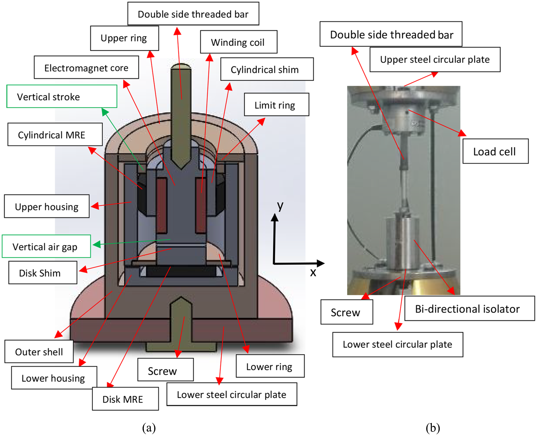
The schematic configuration of the proposed bi-directional shear mode MRE-based vibration isolator is depicted in Figure 1. The MRE isolator consists of 12 parts. The electromagnet core, the cylindrical shim, the disk shim, the upper housing, and the lower housing were fabricated out of pure iron due to its high relative magnetic permeably. The limit ring, the upper ring, and the lower ring were made of stainless steel to confine the magnetic field lines passing only through the parts made of pure iron and finally go across to the two MRE specimens, thereby reducing the leakage flux from the electromagnet core to the upper housing.
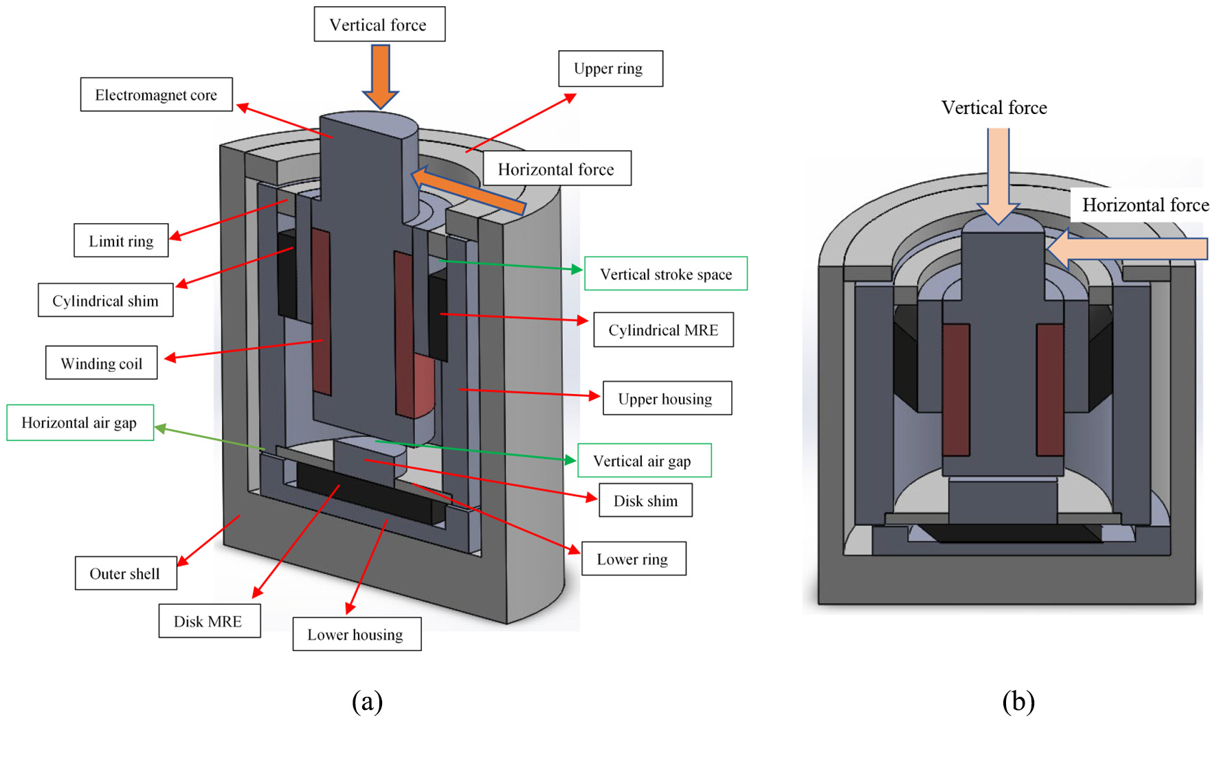
Schematic configuration of the proposed bi-directional shear mode MRE-based vibration isolator (a), and simultaneous bi-directional shear mode operation (b).
The horizontal and vertical air gaps allow the MRE isolator displace and operate in vertical shear and horizontal shear modes, respectively. In the vertical shear mode, only the cylindrical-shaped MRE will go under shear operating and the devised vertical air gap, as shown in Figure 1(a), will not allow disk-shaped MRE to experience any squeeze force. In horizontal shear mode, only the disk-shaped MRE will experience the shear deformation and the designed limit ring prevents the cylindrical MRE from operating in compression mode. Moreover, apart from the vertical air gap, the interval between the limit ring and the cylindrical-shaped MRE is set to 3 mm, which specifies the maximum vertical movement. To enable the horizontal motion of the designed MRE isolator, a small gap of 2 mm between the upper housing and lower housing is reserved. Therefore, the MRE isolator can simultaneously go under vertical shear and horizontal shear modes operation as shown in Figure 1(b) and has the potential application in seat suspension system to reduce vibration coming from the base in two vertical and horizontal directions. Furthermore, one principal advantage of the proposed bi-directional shear mode configuration is attributed to its straightforward assembling process. The exploded view of the MRE isolator was portrayed in Figure 2.
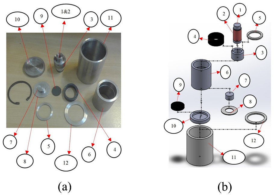
Exploded view of the designed bi-directional shear mode MRE-based vibration isolator (a), and exploded view of the MRE isolator along with its assembling process from the stage 1 to the stage 12 (b).
2.2. MRE fabrication
In this study, two isotropic MRE specimens with particle weight fraction of 70% were fabricated. The MREs contain carbonyl iron particles (type C3518, Sigma-Aldrich), silicone rubber (Silicone sealant, Selleys), and silicone oil (type 378364, Sigma-Aldrich). The iron particles (average diameter of 5 μm) were used as magnetic particles and dispersed in the silicon matrix haphazardly. The weight fractions of MREs’ ingredients such as silicone rubber, silicone oil, and carbonyl iron particles were selected as 20%, 10%, and 70%, respectively. The silicone oil with a viscosity of 5 Pa s was used to avoid particle agglomeration and to enhance their compatibility with the silicone compound. The iron particles were distributed thoroughly in a pre-weighed amount of the silicone oil and then mixed vigorously about 5 min in the room temperature. Afterward, the mixed ingredients were mixed further with the silicone rubber precursor about 10 min. Then, the resulting mixture was placed in aluminum molds after removing air bubbles. Finally, after curing for 24 h at room temperature, hollow cylindrical-shaped MRE specimen with the dimension of 17 mm in height and 6 mm in thickness as well as disk-shaped MRE with dimension of 28 mm in diameter and 7 mm thickness were trimmed from the aluminum molds. The fabricated isotropic MRE samples are depicted in Figure 3.
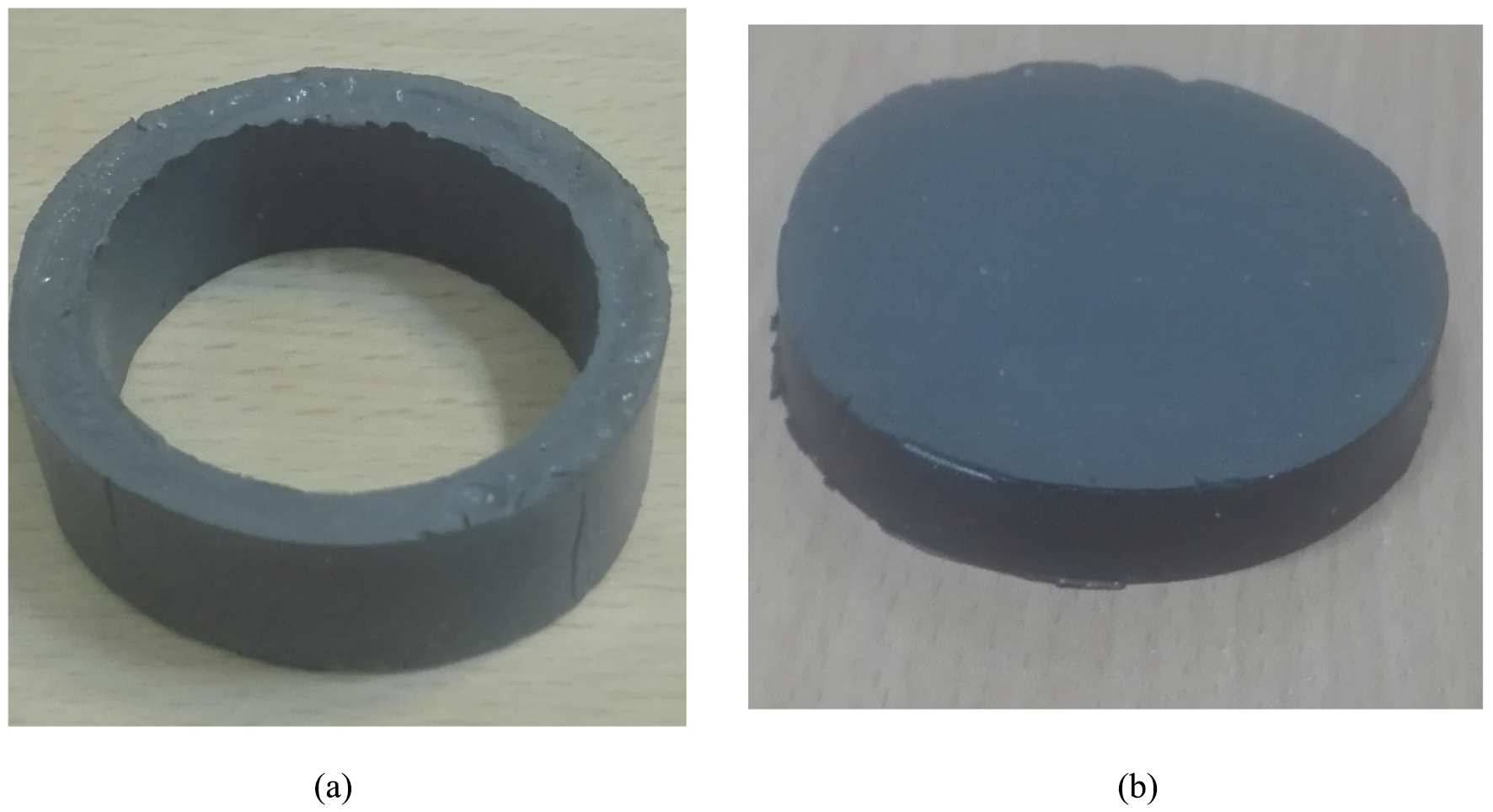
The hollow cylindrical-shaped isotropic MRE with height of 17 mm and thickness of 6 mm (a), and the disk-shaped isotropic MRE specimen with diameter of 28 mm and thickness of 7 mm (b).
It is important to note that for a chain-like structure–based MRE, the optimum volume fraction of iron particles was predicted to be 27% and the relative change in modulus due to a large magnetic field was 50% (Davis, 1999). On one hand, the degree of anisotropy is known to strongly depend on the particle volume concentration of the MRE. It has been reported that anisotropic MREs with greater iron particle volume fraction yield properties comparable to those of the isotropic MRE with the same particle volume fraction (Schubert and Harrison, 2015). Reported studies have also suggested that relatively small increase in the relative MR effect of the anisotropic MRE compared with those of the isotropic MRE, especially for relatively higher particle volume fractions of about 30% (Bellelli and Spaggiari, 2019; Lee et al., 2018). On the other hand, MREs containing <30% volume particle fraction may be damaged under the stress of the absorber mass or weight of structure that MRE is going to support (Lerner and Cunefare, 2007). That’s why in this study isotropic MRE specimens were chosen to be fabricated with particle volume fraction of 30% as they permit more straightforward fabrication process compared to anisotropic MRE, while providing comparable MR effect.
2.3. Magnetic circuit design
The most important step toward developing MRE-based devices is designing an effective electromagnet to generate required magnetic flux to activate the MRE. Electromagnets usually consist of magnetic core and winding coil. The bi-directional MRE isolator can be considered as a magnetic circuit which can direct the magnetic field generated by a winding coil and guiding it from the magnetic core to across within the two MRE samples. To verify the magnetic flux distribution as well as improvement of the circuit, magnetic field analyses were performed by simulating the MRE isolator using a software package called Finite Element Method Magnetics (FEMM) (Meeker, 2010). With this software, the magnetic circuit of the MRE isolator can be quickly investigated, permitting for multiple design iterations prior to component manufacturing. The program is a simple finite element code capable of solving two-dimensional (2D) and axisymmetric magnetic problems. The magnetic circuit portion of the bi-directional shear mode MRE isolator is axisymmetric in nature, thus a more complex three-dimensional (3D) finite element solver is not required. The FEMM software can also analyze the magnetic flux distribution in all parts of the bi-directional shear mode MRE isolator, which is highly dependent on the geometrical dimension and type of materials selected for manufacturing the MRE isolator. Therefore, the magnetic properties such as relative magnetic permeability
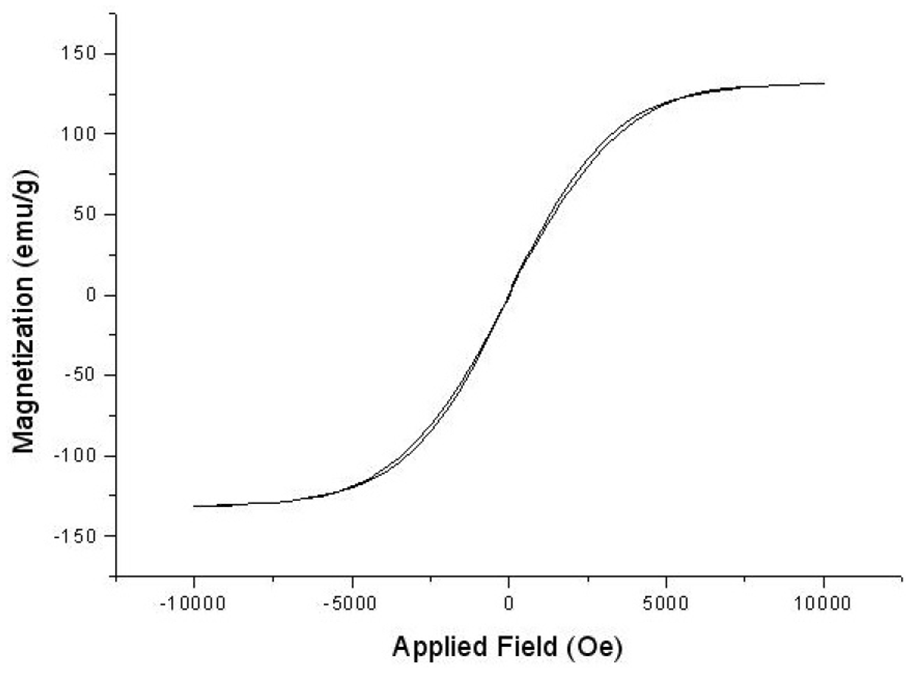
Magnetization curve of fabricated isotropic MRE specimen with 70% weight fraction.
In addition to magnetic properties, the dimension of parts should be determined prior to run the FEMM software. The dimension of the electromagnet core was determined according to the standard fabricated MRE samples. A direct current (DC) of 2500 amp-turns was assumed to apply through insulated conductor copper wire. Therefore, number of turns was obtained as 1300. By considering a suitable current density
As shown in Figure 5, the MRE isolator configuration was entered as a series of points, lines, and areas. Each area was allocated a magnetic material property. The left-most edge of sketch, as shown in Figure 5(a), signifies the axis of symmetry. The software assumes that each area plotted to the right of this line is uniformly revolved around the axis of symmetry, thereby generating a cylindrical volume. After assigning the related boundary condition and generating triangle meshing with 9933 number of nodes, a contour plot of the magnetic flux path and flux density can be realized as shown in Figure 5(b). It is important to note that for axisymmetric magnetic problems, a valid solution can be obtained without explicitly defining any boundary conditions, as long as part of the boundary of the problem lies along r = 0 (Meeker, 2010). The magnetic flux path is marked by the contour lines, which forms a loop through the structure. This plot prepares a crystal-clear graphical representation that signifies how the magnetic material and the MREs direct the path of the magnetic flux. The colors in this plot signify the intensity of the magnetic field within the MRE isolator. The magnitude of magnetic flux density inside the MRE isolator at different locations can also be determined. In the FEMM simulation, it was observed that the magnetic flux density inside the activation area of the two MREs within isolator increases with increasing applied electrical currents. According to Figure 5(b), the flux lines have passed across the electromagnet core, the air gap between the electromagnetic core and the disk shim, the disk MRE, the lower housing, the upper housing, the cylindrical MRE, and the cylindrical shim and have encircled back to the electromagnet core. Besides, Figure 5(b) illustrates that the magnetic field is reasonably uniform and homogeneous in the zones where the cylindrical and the disk-shaped MRE were placed, which guarantees the effectiveness of two MREs under the shear mode operation.
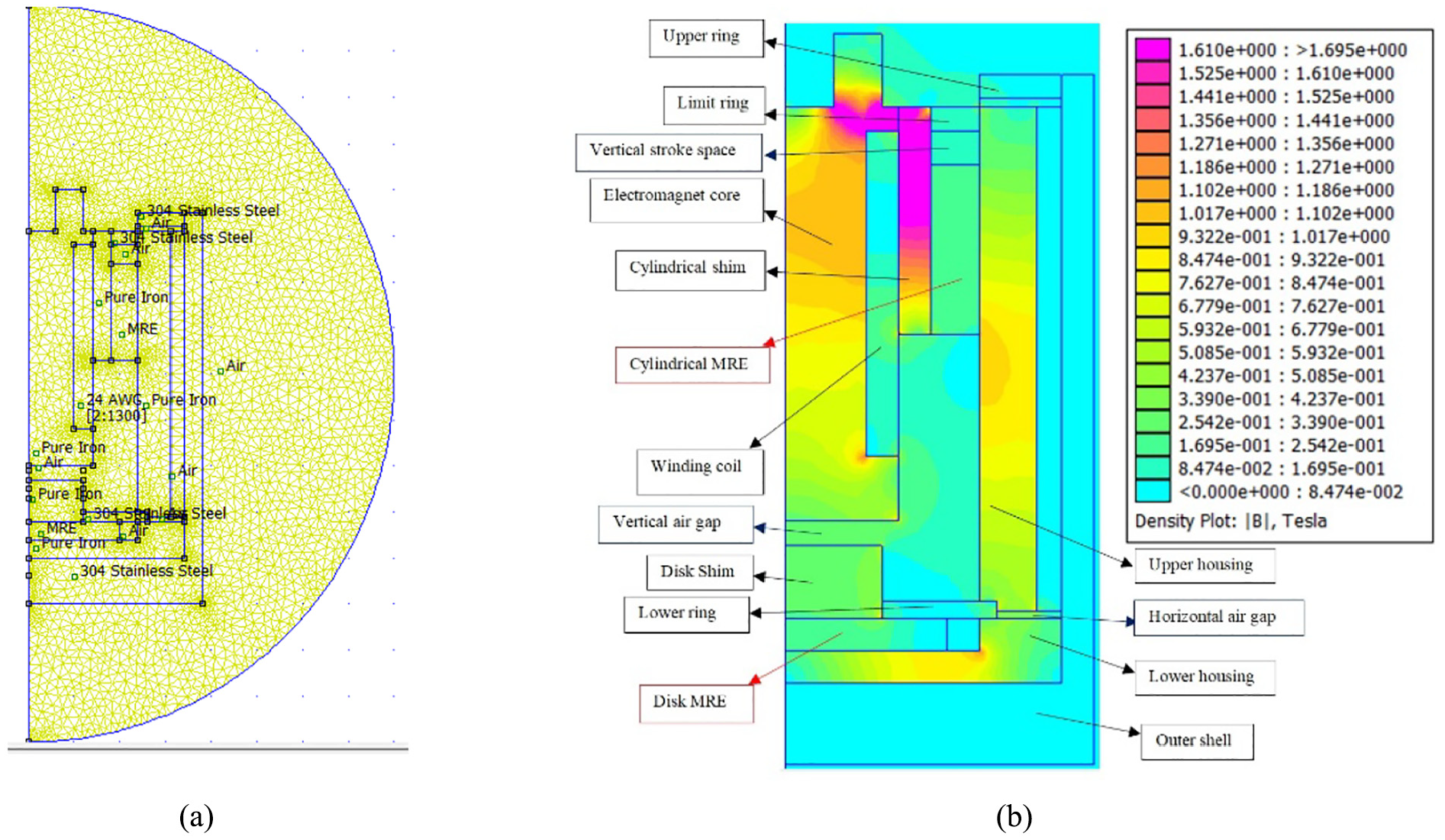
Two-dimensional axisymmetric model of the bi-directional shear mode MRE-based vibration isolator in the FEMM software (a), and the corresponding magnetic flux distribution within the isolator (b).
The results of the average magnetic flux density within two MRE samples for different values of applied electrical current, as well as various levels of air gap between the electromagnet core and disk shim are depicted in Figure 6. It is observed that the magnetic flux density increases with increasing the electrical current. Moreover, by increasing the vertical air gap length, the magnetic flux density decreases. There is a trade-off between the maximum magnetic flux density within MREs and maximum vertical shear displacement. The latter demands large vertical air gap. Luckily in combined magnetic and mechanical loading, by increasing the vertical deformation, the vertical air gap decreases which results in increasing the magnetic flux density within two MREs due to decrease in the reluctance of vertical air gap. According to Figure 6, the vertical air gap between the electromagnet core and the disk shim was finally set to 3 mm, which indicates the maximum vertical shear displacement of the bi-directional shear mode MRE-based vibration isolator. Likewise, to enable the horizontal shear motion of the proposed isolator, a small gap of 2 mm between the lower housing and upper housing was reserved. Furthermore, Figure 6 elucidates the magnetic flux density within disk-shaped MRE and cylindrical-shaped MRE can be reached to 220 and 180 mT, respectively, by setting the electrical current of 1.7 A at vertical gap of 3 mm.
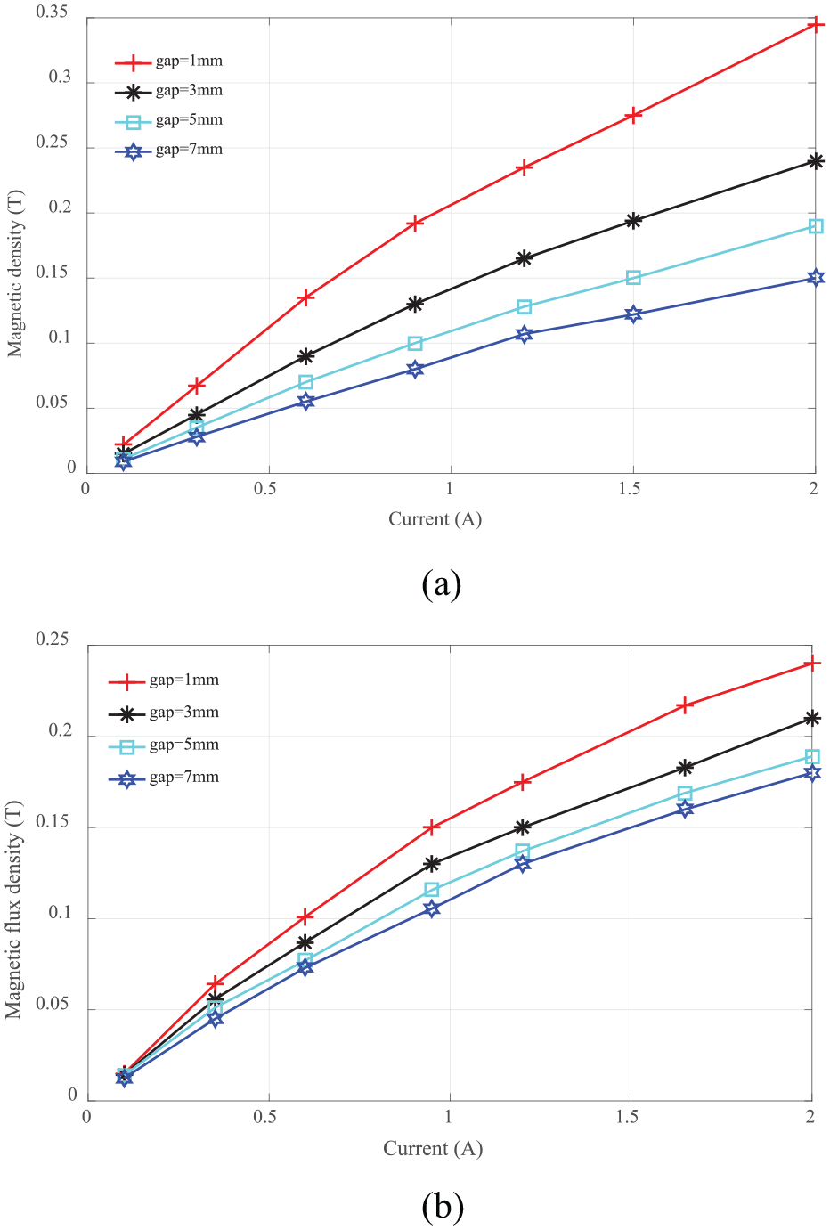
Average magnetic flux density within disk-shaped (a) and cylindrical-shaped (b) MRE sample.
3. Experimental study of the prototype
In this section, two series of experiments were designed for characterization of the bi-directional shear mode MRE-based vibration isolator in the vertical and horizontal shear modes. The sine sweeping-frequency vibration strategy was carried out to evaluate how the bi-directional MRE isolator responds to magnetic and mechanical loadings in these two directions. The methods and the experimental setup designed for each mode of operation are individually described in the next sections.
3.1. Vertical shear mode characterization
Figure 7 illustrates the principal experimental test stand for characterization of the designed MRE isolator in vertical shear mode. The experiments were designed to include relatively broad ranges of strain amplitude, excitation frequency, and magnetic flux density in order to obtain the dynamic characteristics of the MRE isolator over a wide spectrum of mechanical and magnetic loading conditions. The experiments were conducted using a servo-hydraulic Instron 8802 system in the displacement control mode. The methods and the experimental setup designed in the study are described as follow. A vertical shear loading fixture was constructed via a double-sided threaded bar as shown in Figure 7. The vertical shear mode test fixture with the MRE isolator was attached to the upper and lower grip of the Instron via two non-magnetic material circular steel plates. The lower steel circular plate connected to the actuator was attached to the lower part of the MRE isolator. The upper steel circular plate was attached to the load cell and the top grip frame of the Instron. The double-sided threaded bar from the bottom was attached to the MRE isolator and from the top was attached to the load cell. The double-sided threaded bar and the circular plate were made of steel to prevent magnetic flux leakage from reaching to the load cell and the actuator. A power supplier was used to provide electrical current to the electromagnet of the MRE isolator, thereby generating the desired magnetic flux density within the two MREs. This allows variation in the density of the magnetic flux density imposed on the two MRE specimens. Therefore, a series of training set data tests were performed on the MRE isolator in vertical shear mode by varying the magnetic flux density, displacement amplitude, and motion frequency. The mechanical loading was applied using the Instron machine, thus generating a sinusoidal vertical displacement versus time to the MRE isolator. The loading frequencies were set as f = 1, 3, 5, and 8 Hz and the shear displacement amplitudes were set as A = 0.24, 0.48, 0.96, 1.5, and 1.92 mm, which correspond to shear strains of 4%, 8%, 16%, 25%, and 32%, respectively, for the cylindrical-shaped MRE specimen with 6 mm thickness shown in Figure 7(a). The data were acquired under five different magnetic flux densities (0, 70, 110, 140, and 180 mT), which were realized by applying electrical current as 0, 0.6, 0.9, 1.2, and 1.7, respectively. The signals of displacement sensor along with load cell were transferred to a data acquisition instrument for processing and analyzing. Symmetric hysteresis force–deflection curves of tested MRE isolator were obtained, which are discussed in the next section.
Experimental setup for characterizing the bi-directional shear mode MRE-based vibration isolator in in the vertical shear mode: schematic of the MRE isolator (a) and integrated test rig in vertical shear mode (b).
3.2. Horizontal shear mode characterization
Figure 8 demonstrates the principal experimental test stand for characterization of the designed MRE isolator in the horizontal shear mode. A test stand was designed to characterize the MRE isolator in the horizontal shear mode. A horizontal shear loading fixture was constructed via two double-sided threaded bars as shown in Figure 8. According to the horizontal shear mode test fixture, the MRE isolator was attached to the upper and lower double-sided threaded bar. The lower double-sided threaded bar from the bottom was attached to the load cell and from the top attached to the MRE isolator. The upper double-sided threaded bar from the bottom was attached to the MRE isolator and from the top was attached to the load cell. A series of training set data tests were performed by varying the magnetic flux density, displacement amplitude, and motion frequency. The mechanical loading was applied using the Instron machine, thus generating a sinusoidal vertical displacement versus time to the MRE isolator. The loading frequencies and shear strains were set the same as the vertical shear test. The data were acquired under five different magnetic flux densities (0, 100, 130, 160, and 220 mT), which were realized by applying electrical current as 0, 0.6, 0.9, 1.2, and 1.7, respectively.
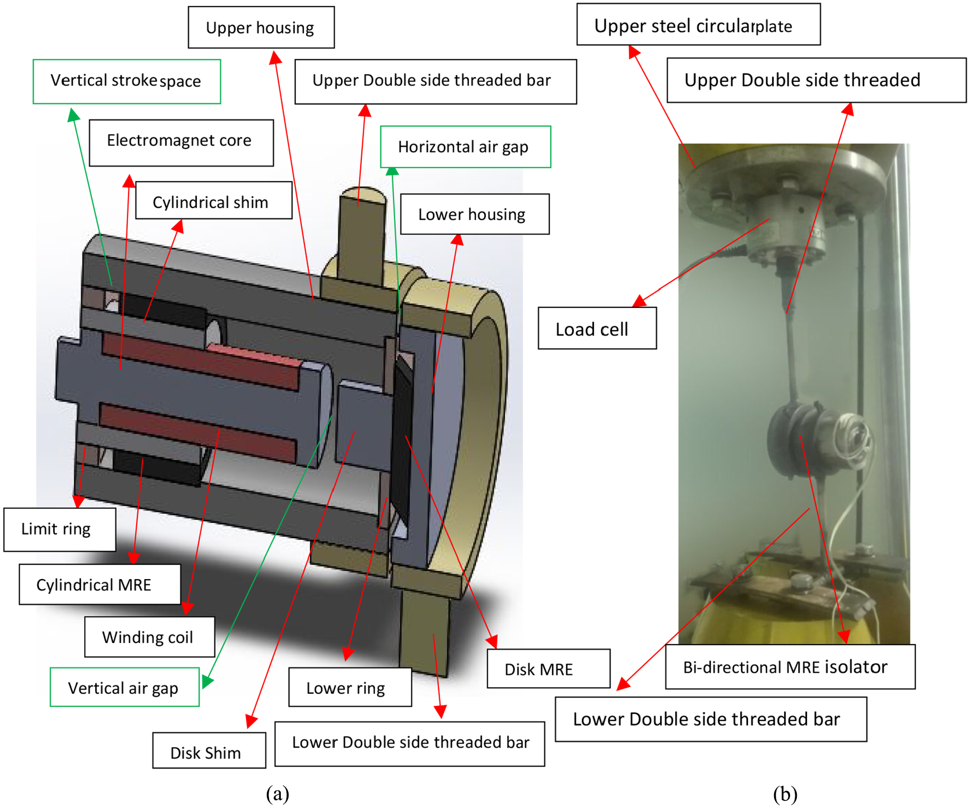
Experimental setup for characterizing bi-directional MRE isolator in horizontal shear mode: (a) schematic of the MRE isolator and (b) integrated test rig.
4. Result and discussion
4.1. Hysteresis loop
In several successive figures, a summary of the behavior of the bi-directional shear mode MRE-based vibration isolator in vertical and horizontal shear modes was schematically elaborated and physically interpreted for the different levels of the magnetic flux density, strain amplitude, and excitation frequency.
4.1.1. Vertical shear tests
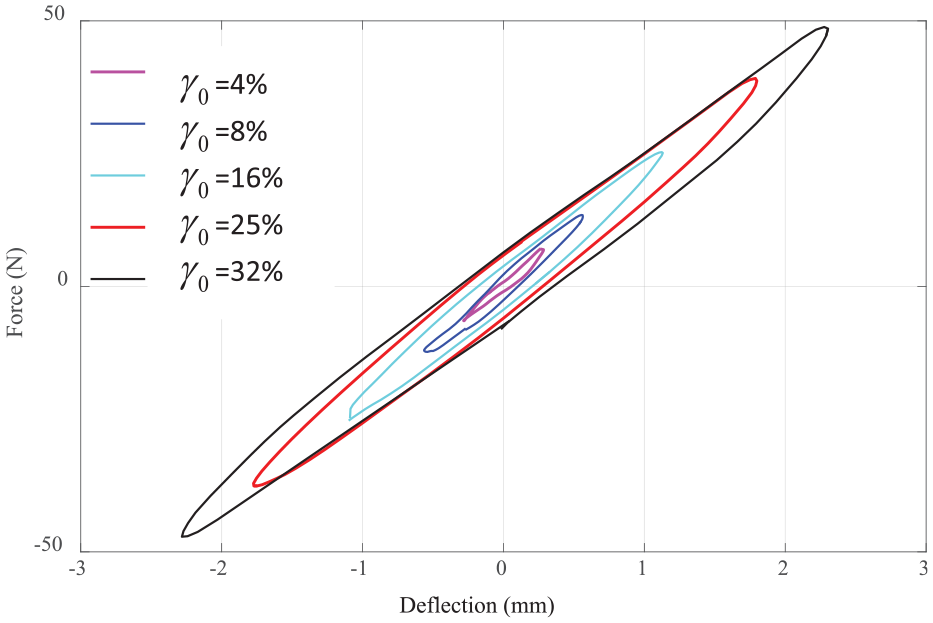
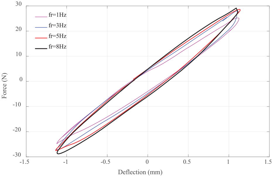
Figure 9 illustrates force–deflection behavior of the MRE isolator considering five levels of strain amplitude ranging from 4% to 32% at magnetic flux density of 140 mT. This figure illustrates that the behavior of MRE isolator starts from strain-softening to strain-stiffening by increasing the strain amplitude from 4% to 32% due to Payne effect and nonlinear viscoelastic nature of MRE, respectively (Vatandoost et al., 2017). Besides, by increasing the strain amplitude, the shape of hysteresis loops changes from linear elliptical to nonlinear nonelliptical shaped and also the enclosed area of the hysteresis loops increases. Figure 10 shows the force–deflection response of the MRE isolator under different frequencies at strain amplitude of 16% and magnetic flux density of 140 mT. By increasing the frequency, the slope of major axis (equivalent stiffness) becomes larger due to the strain-rate stiffening of the MRE. Higher frequencies constrain the time for molecular relaxation motions, thus resulting in higher stresses for a given strain and larger hysteresis loops (Vatandoost et al., 2017). The peak force observed during loading also increases with increasing the strain rate (frequency) as show in Figure 10. In addition, the area of the hysteresis loops increases by changing the frequency from 1 to 8 Hz due to time-dependent hysteretic behavior of MREs. This area indicates the equivalent damping or the dissipated energy in each complete cycle. The variation of the slope or the change in stiffness is more pronounced than change in the enclosed area of the hysteresis loops (equivalent damping), as shown in Figure 10.
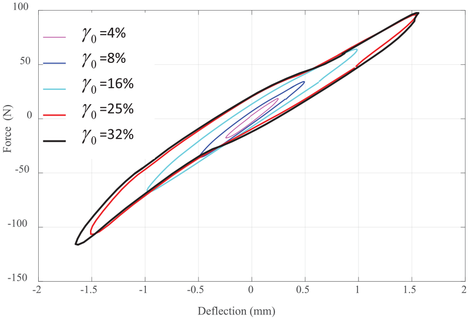
Force–deflection response of the MRE isolator in the vertical shear mode under different levels of strain amplitude at frequency of 8 Hz and magnetic flux density of 140 mT.
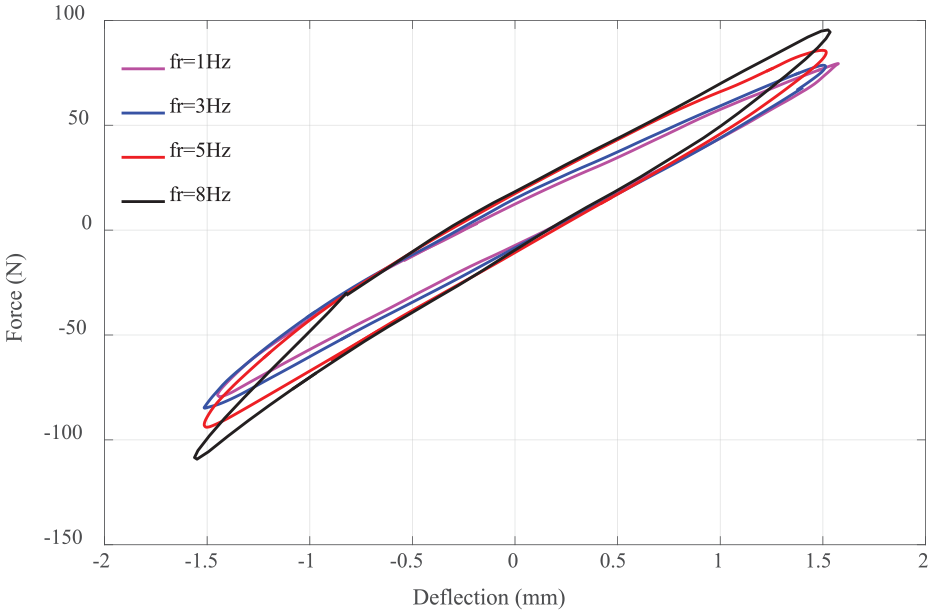
Force–deflection response of the MRE isolator in the vertical shear mode under different levels of frequency at strain amplitude of 16% and magnetic flux density of 140 mT.
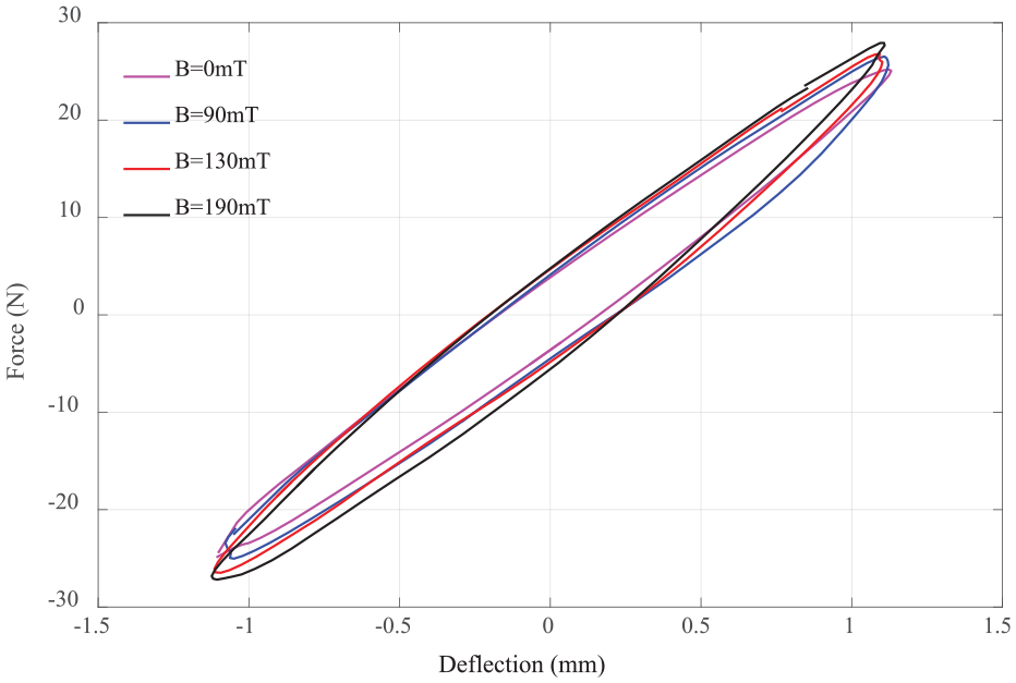
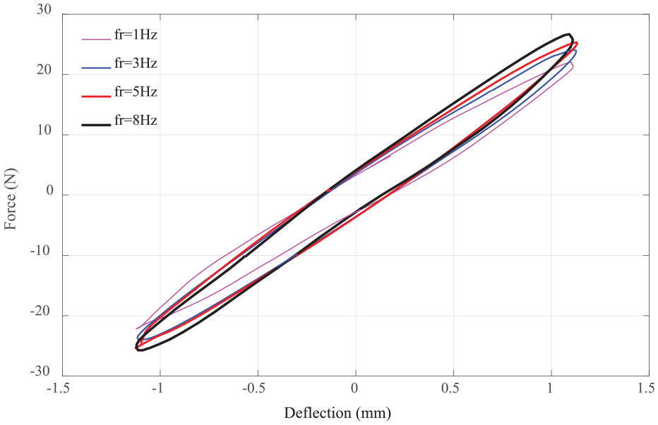
Figure 11 displays how magnetic flux density affects the equivalent stiffness and equivalent damping properties of the MRE isolator. Figure 11 exhibits that by increasing the magnetic flux density, both equivalent stiffness and equivalent damping of the MRE isolator increase. This specifies that the MRE isolator has the capacity to alter its stiffness and damping by controlling the magnetic field, thereby increasing its natural frequency as well as reducing the amplitude of vibration applied on a retrofitted structure with the bi-directional MRE isolator at a resonance frequency. Besides, the contribution of the magnetic flux density results in larger range of shear force, as shown in Figure 11. Figure 12 shows the strain-rate stiffening at zero magnetic flux density. This figure shows that by increasing the frequency, both stiffness and damping of the MRE isolator increased. These increases, however, are not comparable to those caused by magnetic flux density observed in Figure 11.
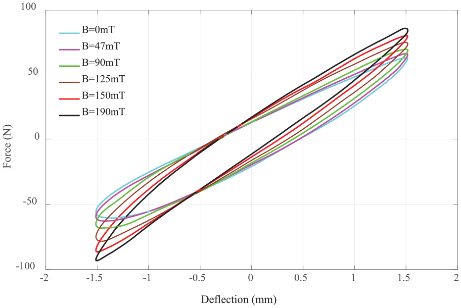
Force–deflection response of the MRE isolator in the vertical shear mode under different levels of magnetic flux density at frequency of 3 Hz and at strain amplitude of 16%.
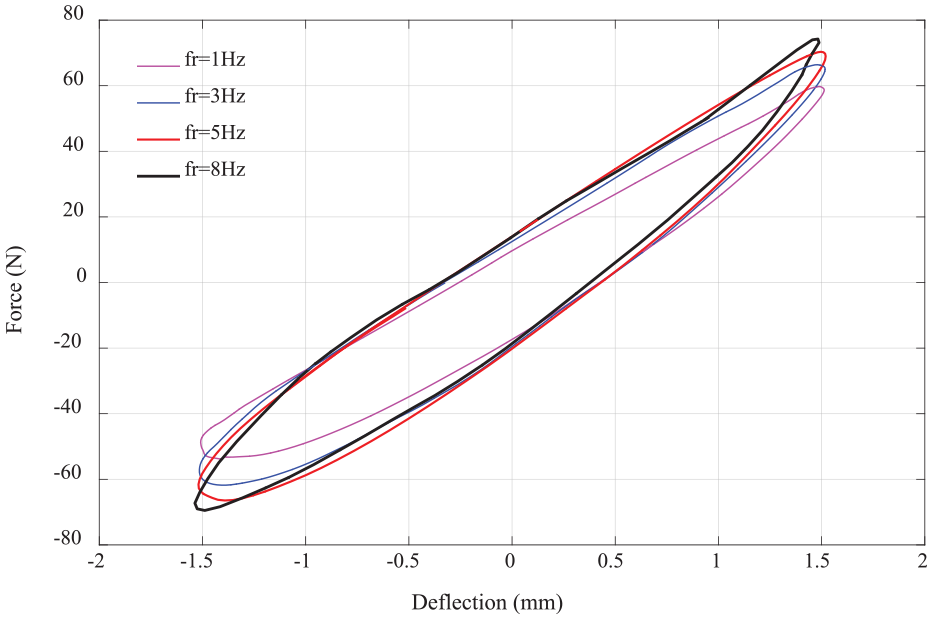
Force–deflection response of the MRE isolator in the vertical shear mode under different levels of excitation frequency under strain amplitude of 16% and zero magnetic flux density.
Figures 9 to 12 have shown no perceptible difference among the tests results attained under shear displacements in the loading and unloading path due to the symmetric nature of the test arrangement as well as MRE feature in the shear mode. In other words, all the experimental hysteresis loops of tested MRE isolator in vertical and horizontal shear modes, as can be seen later, are symmetric about the origin unlike the tension–compression mode operation (Norouzi et al., 2017; Vatandoost et al., 2017), thereby dramatically facilitating modeling of the symmetric hysteresis loops, and all the advantages they offer.
4.1.2. Horizontal shear tests
Figure 13 demonstrates the force–deflection behavior of the MRE isolator at frequency of 8 Hz and zero magnetic flux density. The hysteresis loops shown in this figure are more elliptical than that of corresponding hysteresis loop obtained in vertical shear test at 140 mT as shown in Figure 9. This is mostly due to the contribution of magnetic field nonlinearity in MRE behavior. The force–deflection response of the MRE isolator for different excitation frequencies and the effect of magnetic flux density on the equivalent stiffness and equivalent damping properties of MRE isolator for horizontal shear tests are illustrated in Figures 14 to 16. As can be seen, the equivalent stiffness and damping behaviors are the same as vertical shear tests. Also, Figure 15 demonstrates how force induced in MRE increases due to applied external magnetic flux density at strain amplitude of 16%. Furthermore, Figures 14 and 16 show that the effect of the excitation frequency on stiffening the MRE specimen is quite larger in absence of the magnetic field compared to that in presence of the magnetic field, due to the magnetic field stiffening of the MRE sample.
Force–deflection response of the MRE isolator in the horizontal shear mode under different levels of the strain amplitude at frequency of 8 Hz and magnetic flux density of 0 mT.
Force–deflection response of the MRE isolator in the horizontal shear mode under different levels of the excitation frequency at strain amplitude of 16% and magnetic flux density of 160 mT.
Force–deflection response of the MRE isolator in the horizontal shear mode under different levels of magnetic flux density at frequency of 5 Hz and at strain amplitude of 16%.
Force–deflection response of the MRE isolator in the horizontal shear mode under different levels of the excitation frequency at strain amplitude of 16% and zero magnetic flux density.
Considering results obtained in both vertical and horizontal shear modes, it is evident that the nonelliptical hysteresis loops are more pronounced in the vertical shear mode than the horizontal shear mode. This is because in the vertical shear mode, as the strain amplitude increases, the vertical gap shown in Figure 7 unavoidably decreased, thereby increasing the magnetic field induction in the magnetic circuit along with cylindrical MRE; thus, the extra magnetic flux density causes nonlinear hysteresis loops in vertical shear mode.
4.2. Effect of strain amplitude on the viscoelastic behavior of the MRE isolator
In this section, the effects of strain amplitude on the viscoelastic behavior of the bi-directional shear mode MRE-based vibration isolator, such as shear storage modulus
Viscoelastic parameters of the MRE isolator in the vertical shear mode at frequency of 5 Hz, and magnetic flux density of 150 mT.
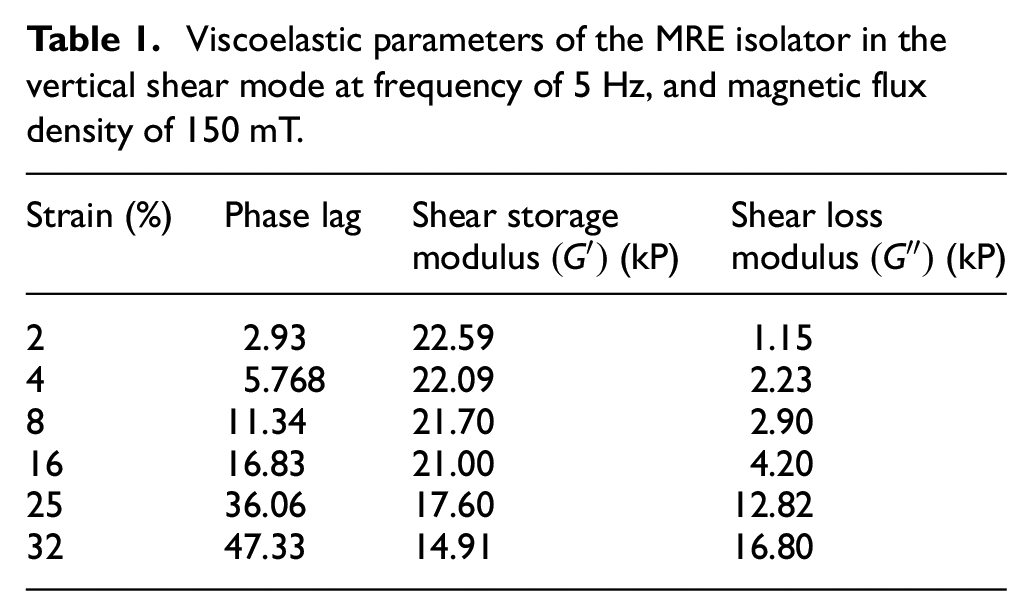
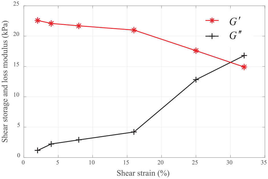
Variation of the shear storage modulus
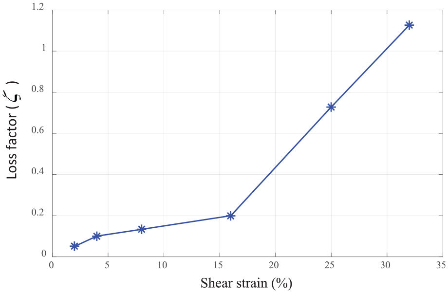
Variation of the loss factor
Figure 17 illustrates the trend of the shear storage modulus
4.3. Vibration attenuation performance of the MRE isolator
4.3.1. Basic mathematical model
Considering Figure 7, the dynamics of the presented bi-directional shear mode MRE-based vibration isolator can be disintegrated into the vertical direction (y-axis) and horizontal direction (x-axis), and the corresponding schematics of the mode of operations are presented in Figure 19(a) and (b), respectively. Therefore, according to Figure 19, the basic mathematical model of the bi-directional shear mode MRE-based vibration isolator in the vertical and horizontal directions, can be expressed as
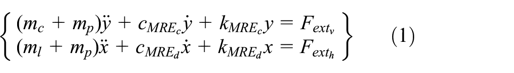
where
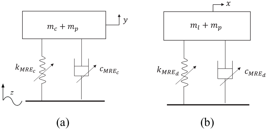
Basic mathematical models of the bi-directional shear mode MRE-based vibration isolator: the vertical direction (a) and the horizontal direction (b).
4.3.2. Vibration attenuation performance
In order to further assess the vibration suppression performance of the bi-directional shear mode MRE-based vibration isolator, its ability to shift the natural frequency in the vertical shear mode is evaluated in this section. The integrated system employing the proposed prototype MRE-based vibration isolator can be considered as an SDOF system, which comprises of a payload mass and a viscoelastic component. The payload mass can be simulated as a combination of the upper part of the electromagnet core assembly within the MRE isolator as well as the miscellaneous hardware attached on the top of electromagnet. Figure 19(a) expresses the equivalent mechanical model of the MRE isolator as an integrated vibration attenuation system, which is a simplified operational model of the proposed MRE isolator system (Figure 7) in the vertical shear mode.
As shown in Figure 19(a),

where for an SDOF system shown in Figure 19(a), the vibration transmitted to total payload mass
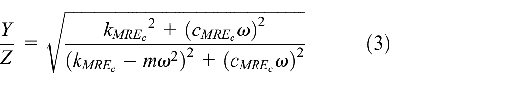
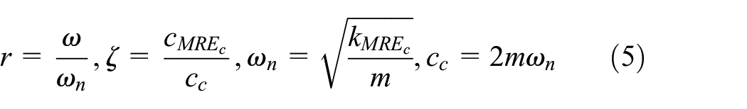
where can be further simplified based on the frequency ration
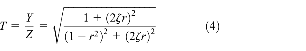
where r,
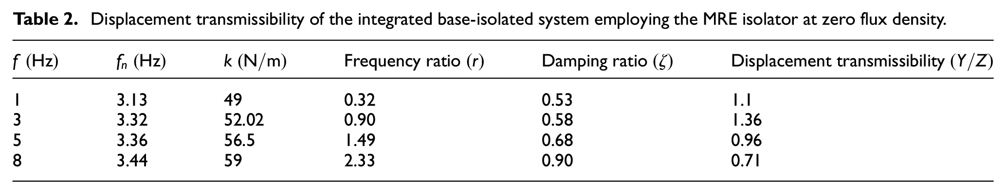
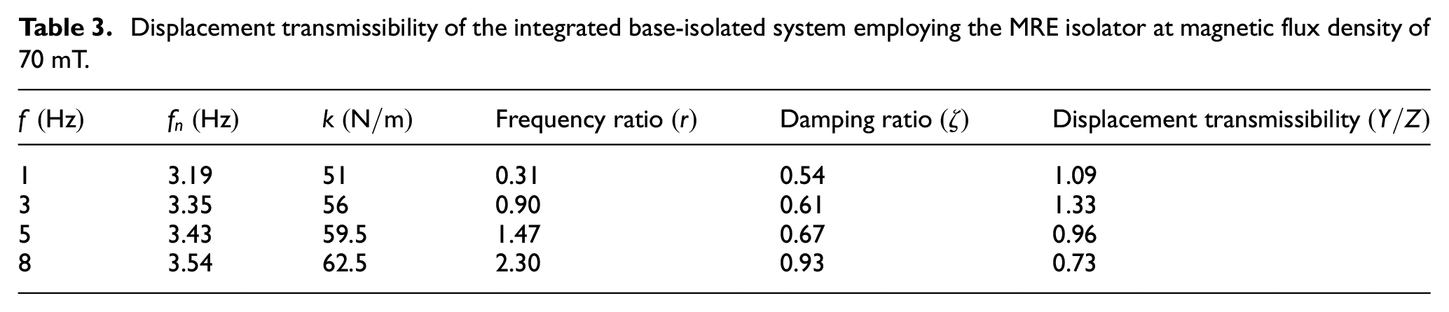
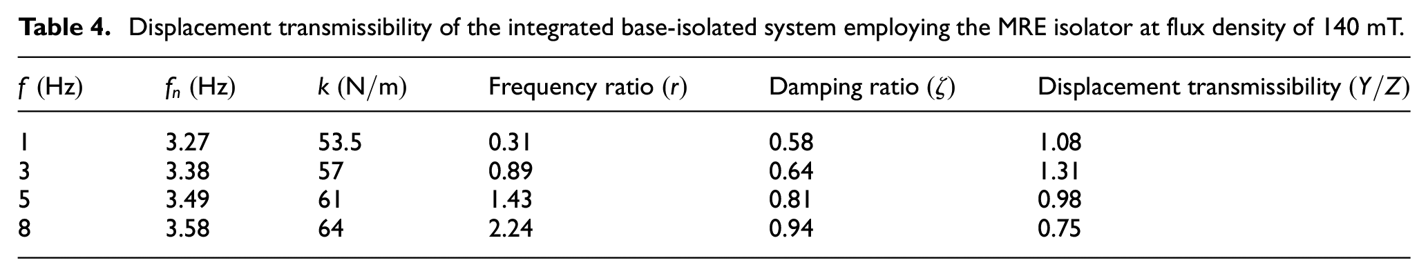
To assign the parameters of the integrated base-isolated system with variable stiffness and damping properties, the experimental results related to frequency of 1, 3, 5, and 8 Hz as well as magnetic flux densities of 0, 70, 140, and 180 mT are employed. The corresponding displacement transmissibility for each case then calculated according to equation (4) and summarized from Table 2 to 5.
Displacement transmissibility of the integrated base-isolated system employing the MRE isolator at zero flux density.
Displacement transmissibility of the integrated base-isolated system employing the MRE isolator at magnetic flux density of 70 mT.
Displacement transmissibility of the integrated base-isolated system employing the MRE isolator at flux density of 140 mT.
Displacement transmissibility of the integrated base-isolated system employing the MRE isolator at magnetic flux density of 180 mT.
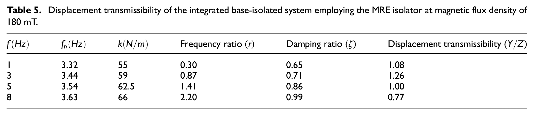
The integrated base-isolated system employing the bi-directional MRE isolator in vertical shear mode yielded natural frequency shifts of 6.1% and 5.5% for excitation frequency of 1 and 8 Hz, respectively, with a small increment in the magnetic flux density, ranging from 0 to 180 mT. Relatively similar results can be obtained in the horizontal shear mode. Such a relatively good change in the natural frequency of the bi-directional MRE-based vibration isolator suggests its greater potential for applications in vibration control, particularly when simultaneous isolation in two perpendicular directions is required, such as in seat suspension systems.
Schematically, Figure 20 illustrates the displacement transmissibility of the integrated system employing the bi-directional shear mode MRE-based isolator for a frequency range of 1–8 Hz under different levels of magnetic flux density. According to Figure 20, when the magnitude transmissibility, T, reaches its maximum value, the corresponding exciting frequency is determined as the resonance frequency. From controlling point of view, the results of displacement transmissibility indicates that the intersection of off-state (zero magnetic flux density) and on-state (magnetic flux density of 70, 140, and 180 mT) can be considered as a reversal frequency in on- and off-based control strategies for effectively attenuating vibration amplitude. In other words, when the forced motion frequency is higher than the reversal frequency, the applied control magnetic flux density can be set at the maximum value, 180 mT, and when the forced motion frequency is lower than the reversal frequency, the applied control magnetic flux density can be set to zero, so-called passive mode. Figure 20 also demonstrates that as the magnetic flux density varies from 0 to 180 mT, the vibration transmissibility increases near to the resonance
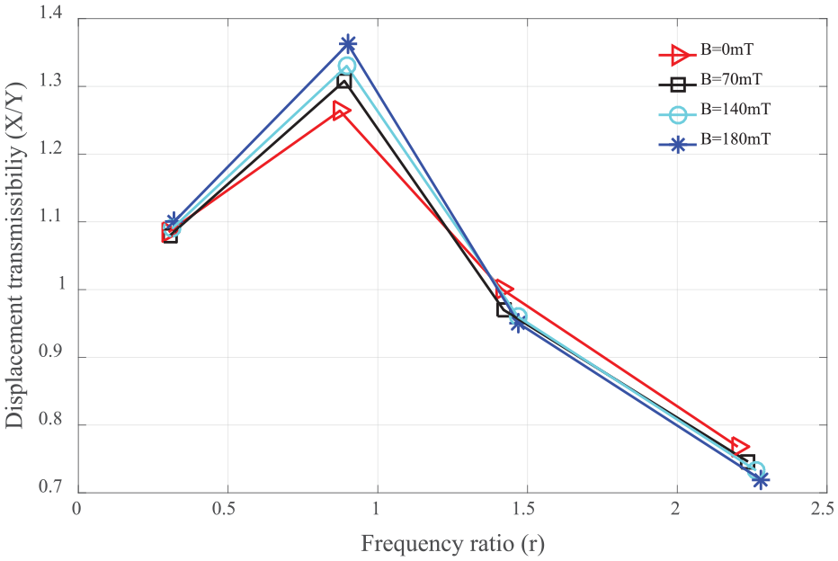
Displacement transmissibility of integrated system employing MRE isolator for different levels of magnetic flux density.
5. Concluding remarks
A novel bi-directional shear mode MRE-based vibration isolator was designed and manufactured. Two fixtures were designed to assess the vibration mitigation performance of the designed MRE isolator in two vertical and horizontal shear modes. A finite element analysis using FEMM software was carried out to design an effective electromagnet, to investigate the magnetic flux distribution inside two MRE specimens, and to reach to a trade-off between maximum permissible vertical shear displacement of the MRE isolator and magnetic flux density within two MREs. The effects of magnetic flux density, strain amplitude, and loading frequency on the equivalent stiffness and equivalent damping coefficients of the MRE isolator were studied in both vertical and horizontal shear modes. Maximum MR effects of 35% and 27% were obtained for the vertical and horizontal shear modes, respectively. The integrated SDOF system employing the bi-directional MRE-based isolator in vertical shear mode yielded natural frequency shifts of 6.1% and 5.5% for excitation frequency of 1 and 8 Hz, respectively, with a small increment in the magnetic flux density, ranging from 0 to 180 mT. Moreover, the corresponding displacement transmissibility of the SDOF system decreased as the magnetic flux density increases. The potential for realizing such a capacity of employing the bi-directional shear mode operation, individually and simultaneously, suggests reasonably well promising features of the proposed bi-directional shear mode MRE-based isolator for applications required vibration mitigation in two perpendicular modes such as seat suspension systems. Future works are being directed toward developing a novel phenomenological model that can predict the dynamic behavior of the proposed MRE-based isolator as well as linking the FE analysis with an artificial intelligence (AI)-based optimization algorithm in order to seek the optimal parameters of the bi-directional shear mode MRE-based isolator.
Footnotes
Declaration of conflicting interests
The author(s) declared no potential conflicts of interest with respect to the research, authorship, and/or publication of this article.
Funding
The author(s) received no financial support for the research, authorship, and/or publication of this article.