
Abstract
The optical fiber smart composite structures have been widely applied for the structural health monitoring, and the packaging technique of integrating optical fiber sensor with host structure is one of the key issues. The flame spraying coating provides strong adhesive strength with good heat resistance, which is particularly suitable for the packaging applications in harsh environments. However, the elaboration process of flame spraying coating–based fiber composite structure faces great challenges due to the flame spraying mechanisms. This study evaluates numerically an overall effect of flame spraying coating formation process on the structural and the optical properties of the embedded fiber optic based on a three-dimensional finite element model. First, the lumped capacitance method is used; both the average heat flux density in the whole spraying process and the specific heat flux density of each torch sweep are estimated to initialize the thermo-mechanical modeling. Then, the stress distributions in both radial and axial directions of the embedded fiber are discussed separately. Next, the variation of refractive index of the embedded fiber optic due to the residual strain is also investigated. Finally, the elaboration parameters including torch displacement and velocity are evaluated and optimized. The simulation results show that the embedded fiber optic maintains good structural and optical properties with the presented elaboration conditions, and therefore its transmission and sensing performance can be ensured.
1. Introduction
Structural health monitoring is the key technique which is applied widely in the fields of aviation, energy, petrochemical, and civil engineerings, such as aircraft manufacture, oil pipeline, bridge and tunnel, and so on (Chen et al., 2018; Li et al., 2004; Yuan et al., 2008). In recent years, the optical fiber smart composite structures are proposed, and they are able to realize the self-diagnosis and the online monitoring of the system structure. As for the fabrication of fiber composite structure, the packaging technique of integrating optical fiber sensor with the host structure is one of the key issues. At present, the mechanical bracket and the adhesives are two main packaging techniques (Biswas et al., 2010; Sasy Chan and Zhou, 2014; Zou et al., 2015). The mechanical bracket needs the additive devices, and therefore it is not able to provide enough adhesion the host structure and the embedded fiber sensor. The adhesives, such as ceramic cement and epoxy resin, are not suitable for the operation in harsh environments due to their poor reliability. For example, in high-temperature environments, the adhesive layers are easy to soften and deform or even damage due to the accumulation of residual stress. When compared with the traditional packaging techniques, the flame spraying technique solves perfectly these shortcomings. Its principle consists of melting the feedstock materials into individual molten particles by high-temperature combustion and then propelling onto the substrate surface to form the coating layers which are used to protect the substrate material (Berger, 2015; Brake et al., 2017; Cinca et al., 2013; Gupta et al., 2017). The deposited coating layers are heat-resistant, corrosion-resistant, antioxidant, and are able to provide good bonding strength with high reliability. All these advantages make it a promising candidate for structural health monitoring in the harsh environment.
A comprehensive study involving flame spraying coating–based fiber composite structure should, first of all, examine the overall effect of the given fabrication process and the deposited coating on the structural property of the embedded fiber optic. However, the process of embedding a fiber optic into flame spraying coating faces great challenges. First, the strong thermal impact which is generated by the in-flight molten particles may destroy directly the embedded fiber. Second, the thermal stresses which are accumulated during the elaboration process influence greatly the adhesive strength the embedded fiber and the host structure (Chen et al., 2014; Lima et al., 2017; Wu et al., 2014) and finally worsen the stability and the lifetime of the smart structure. Third, the refractive index of the embed fiber optic is also modified mainly due to the elasto-optic effect (Bichler et al., 2012), and therefore the optical property of the smart composite structure may be affected. Briefly, a thermo-mechanical analysis should be conducted before the fabrication process to evaluate the interaction mechanism the embedded fiber and the flame spraying coating. In the author’s preliminary work (Yi et al., 2018), a two-dimensional (2D) numerical model is built up to evaluate the behavior of embedded fiber optic. However, in this preliminary study, the nature of 2D model itself limits the analysis. Specifically speaking, only the stress distribution of the fiber cross section is evaluated, and the stress level along the fiber length is not yet analyzed due to the computational complexity. Besides, the dynamic movement path of the spraying torch is not considered in the previous analysis. In a word, a three-dimensional (3D) model is more demanding to approach the real fiber embedding process, and all these challenges lead to the objective of this study.
This study demonstrates systematically the overall effects of the flame spraying process and the deposited coating on the structural property as well as the optical property of the embedded fiber optic based on a 3D finite element model. First, the principle of the flame spraying technique is illustrated briefly, and the lumped capacitance method is used to determine the actual average incident heat flux density as well as the specific heat flux density generated during each spraying torch sweep. These two values are used to initialize the thermo-mechanical modeling. Then, the stress distributions of the embedded fiber optic in both radial and axial directions are investigated, respectively. Next, the variation of refractive index of the embedded fiber optic due to the elasto-optic effect is also investigated. Finally, the optimized elaboration conditions of the spraying torch path including torch displacement and velocity are discussed thoroughly. This study provides an effective method to evaluate quantitatively the overall effect of flame spraying process on the structural and the optical properties of the embedded fiber optic. It lays a good foundation for the experimental fabrications of the future flame spraying coating–based composite structure with the embedded fiber optic sensor, which can be further used for monitoring applications such as temperature/strain sensing.
2. Embedding technique
The oxy-acetylene flame spraying is selected as the embedding technique, and the whole spraying process consists of the heating process and the following pure cooling process. Figure 1 shows the experimental setup; a fiber optic is fixed onto the substrate surface, and two masks are placed on both upper and lower ends to fix the embedded fiber length. During the flame spraying process, the coating materials are molten as the individual molten droplets (dozens of microns in diameter) by the high-temperature flame which is generated by the Rokide-type torch, and then impacted randomly onto the substrate surface by the high-speed compressed air stream. Once the molten droplets reach the substrate surface, they are solidified and deposited rapidly as a layer of coating. The torch sweeps in the horizontal direction back and forth, and it is driven automatically by the robot with the predefined movement path and the velocity. After several torch passages, the multi-layer of coating is finally formed. Generally speaking, the torch displacement in the horizontal direction is set much larger than the substrate width so that part of heat flux is evacuated from both sides; this avoids the over-accumulation of heat flux inside the embedded fiber optic and therefore reduces the risk of fiber damages. Besides, two venturis are placed on both the front and rear sides of the substrate to provide the forced convection cooling during the whole flame spraying process. The initial experimental operation parameters are shown in Table 1.
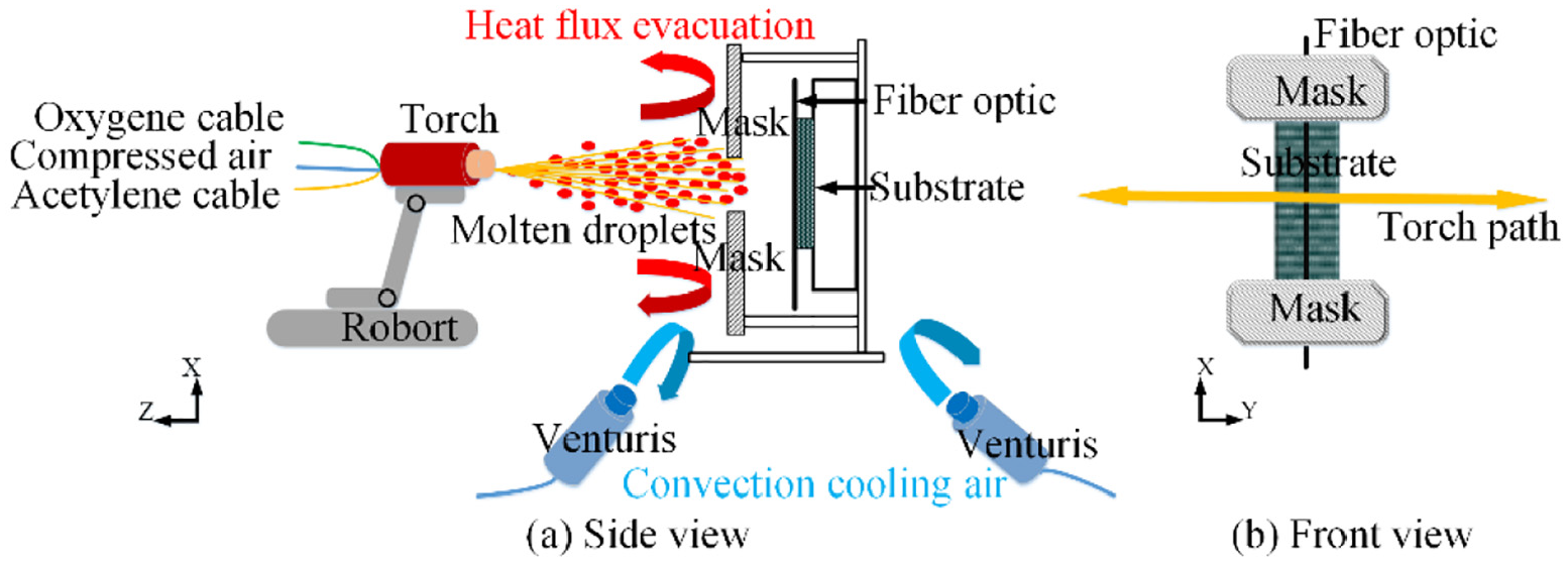
Diagram of the experimental setup.
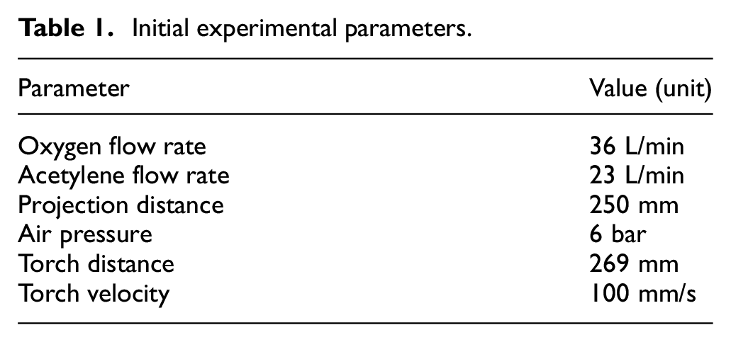
Initial experimental parameters.
3. 3D model
3.1. Model definition
A 3D finite element model using COMSOL 4.3b is built up to simulate an elaboration process of a fiber optic embedding into the flame spraying coating. The model geometry/mesh and its cross-sectional diagram are shown in Figure 2. It consists of the substrate, the coating, and the embedded fiber optic. The substrate is built as a cuboid with a length of 4 mm, a width of 2.5 mm, and a thickness of 1 mm. The multimode fiber consisting of the fiber core, the cladding, and the metal protective coating is selected, and they are modeled as the multi-layer concentric cylinders with diameters of 100, 140, and 200 µm. The coating layers are deposited uniformly on the substrate and the fiber surface. Besides, a semicircular groove is designed to facilitate fiber implementation (Figure 2).
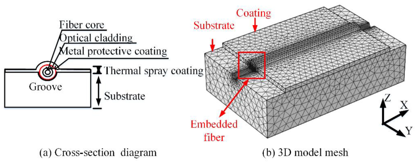
Model geometry and mesh.
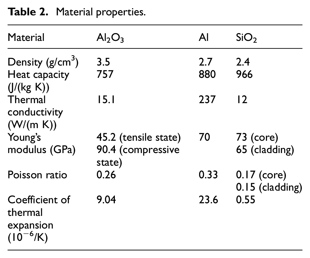
The material properties are listed in Table 2. Aluminum is selected as the substrate material, and alumina is selected as the coating material due to its high-temperature resistance. The fiber core and the optical cladding are both made of silica, and their thermo-mechanical properties exist a minor difference due to the different doping materials. Besides, the metal protective coating material of the fiber optic is aluminum.
Material properties.
3.2. Determination of the actual incident heat flux density
During the fiber embedding process, the flame spraying coating is deposited over the fiber layer by layer, and the stress evolution the multi-coating layers and the embedded fiber is complex considering the coating growth process. In this study, an efficient method is used by assuming the coating layers as an entirety, and then applying the average net incident heat flux onto the coating surface; hence, the thermo-mechanical behavior of the embedded fiber optic can be evaluated together with the boundary conditions. Obviously, the determination of the actual incident heat flux density which occurs during the flame spraying process is vital to initialize the model.
In order to determine the incident heat flux density, a lumped capacitance method is proposed. It assumes that the surface resistance of the system limits its internal heat flow under conditions that the Biot number (defined as Bi = h·L/k) is much less than 0.1. In our case, the substrate thickness L is 1 mm, and the thermal conductivity coefficient k is 237 W/(m K), and the forced convection heat transfer coefficient h is normally several hundred, and therefore the Biot number is definitely less than 0.1. Then, the transient temperature of the composite structure can be assumed as spatially uniform and only in function of time.
Based on this method, the complex heat flux evolution during flame spraying is converted into a theoretical thermal balance model, which signifies that the incident heat flux energy is balanced by the thermal energy accumulated inside the structure and the thermal loss by convective cooling. Then, the thermal balance model is expressed as a first-order differential equation, as shown below
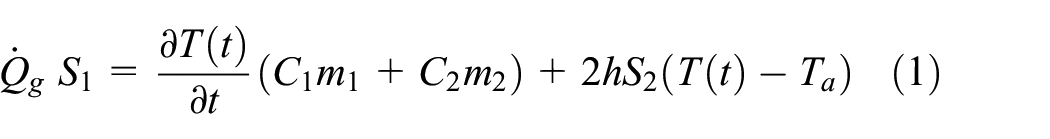
where the first item represents the incident heat flux power, the second item represents the heat flux power accumulated inside the composite structure, and the third item represents the thermal loss by the convective cooling.
The first-order differential equation (1) can be solved out based on the Laplace transformation, and the solution is
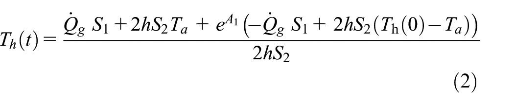

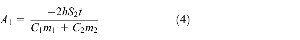
where
Besides, the evaluation of incident heat flux density launched by the torch during each sweep is also important to the optimization of elaboration conditions. If the torch movement path and the coating growth process are taken into consideration, equation (4) is converted into
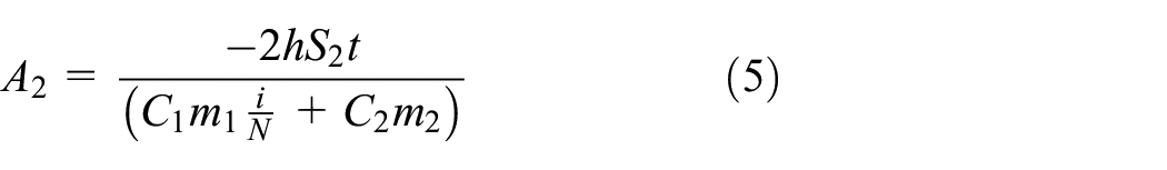
where N is the total numbers of the total torch sweep and

where
3.3. Thermo-mechanical analysis
In the presented 3D thermo-mechanical model, two studies are conducted. In the first study, the average stress level of the embedded fiber optic in both radial and axial directions are discussed separately, and the results are compared with the theoretical ultimate tensile strength of silica fiber. In this modeling, the average thickness of one coating layer is set as 11 µm based on the experimental measurements, and 10 coating layers are defined. Besides, the average net incident heat flux density during the whole flame spraying process is estimated at 24.7 kW/m2 according to equations (2)–(4) and the experimental thermogram recordings. Finally, the flame spraying duration is set as 60 s to achieve the full heating, and then it follows the pure cooling process.
In the second study, a comparative analysis is conducted to evaluate the elaboration conditions including the torch displacement and the velocity (Figure 3). In this study, the torch movement path is considered, the heat flux distribution launched by the torch is assumed as the 3D Gauss form (Bolot et al., 2014), and its central maximum heat flux density value is calculated as 96 kW/m2 according to equations (5)–(7) and the experimental thermogram recordings. Besides, only one coating layer is considered, which corresponds to one torch sweep. The specific comparative conditions of the modeling are described below.
Comparative test (1): Torch velocity varies from 25 to 50, 100, and 200 mm/s, and the torch displacement is fixed as 200 mm.
Comparative test (2): Torch displacement varies from 50 to 100, 150, and 200 mm, and the torch velocity is fixed at 100 mm/s.
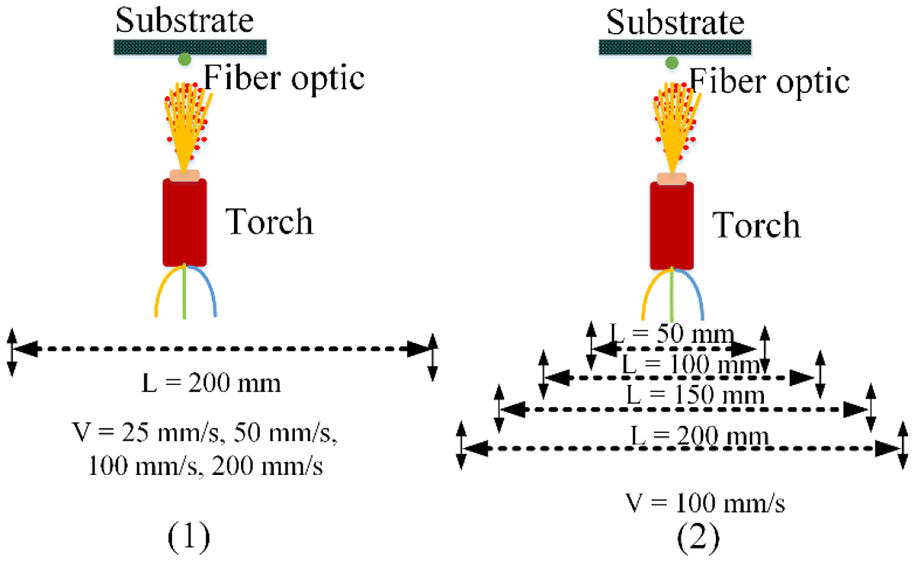
Comparative test conditions of the 3D modeling.
For both studies, the initial temperature and the ambient temperature are set as room temperature of 292 K. The thermal calculations are first conducted, and then the thermal results are applied as the heat load on the model, and the mechanical analysis is conducted as follows. During the mechanical analysis, the displacement-freedom of the top-left corner of the substrate is defined as zero in all directions, since this corner of the substrate is fixed by the screws and nuts during the experiment. The modeling results of the firststudy are indicated in Figures 4 to 7, and the modeling result of the secondstudy is discussed in Figure 8.
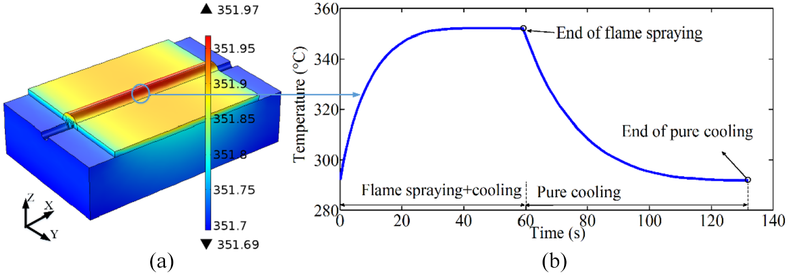
Thermal results of the 3D model: (a) temperature distribution of the composite structure at the end of flame spraying and (b) temperature evolution trace of the central point of the embedded fiber optic.
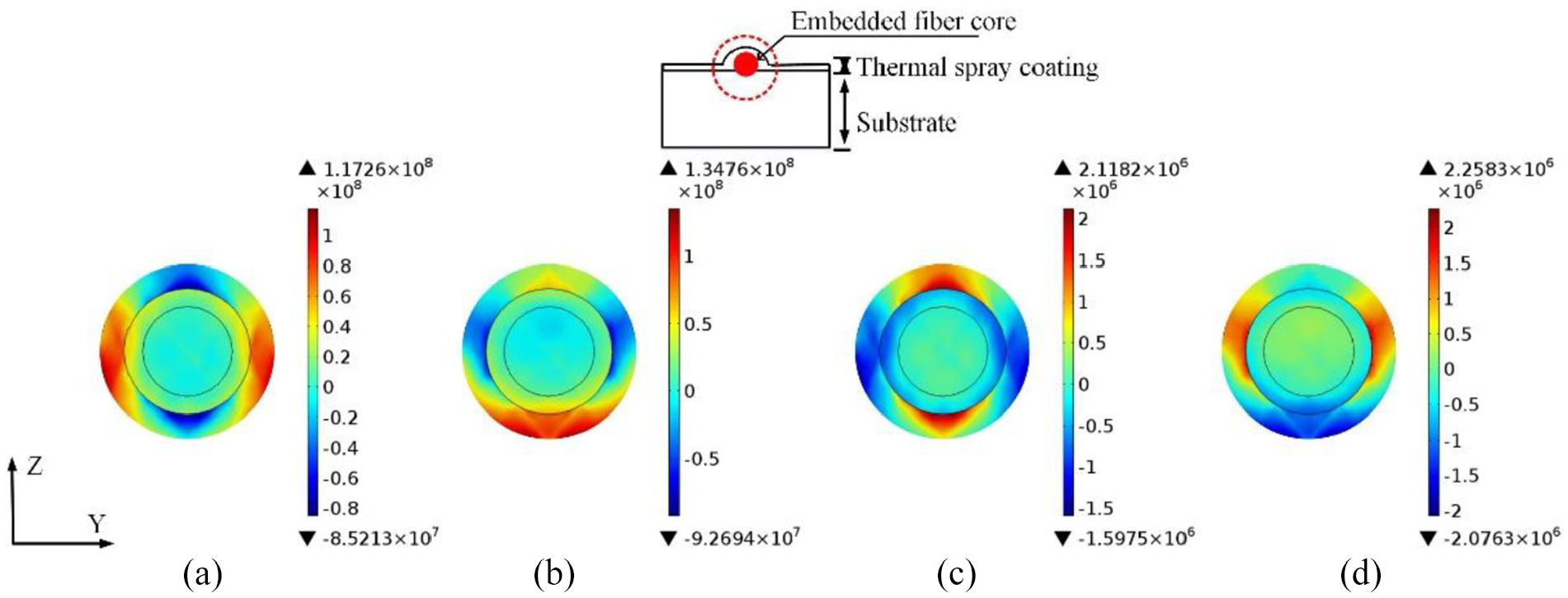
Modeling results of stress distribution of the fiber optic cross section: (a) end of flame spraying, Y component; (b) end of flame spraying, Z component; (c) end of pure cooling, Y component; and (d) end of pure cooling, Z component (positive values represent the tensile stress and negative values represent the compressive stress, same for the following analyses).
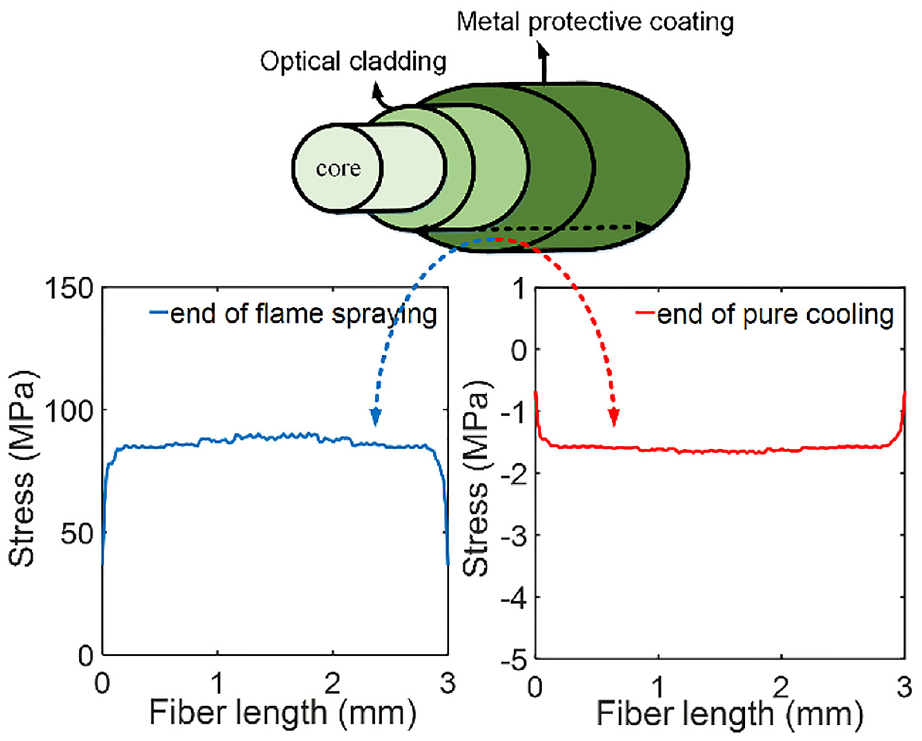
Modeling results of stress distribution along the embedded fiber length: (a) end of flame spraying and (b) end of pure cooling.
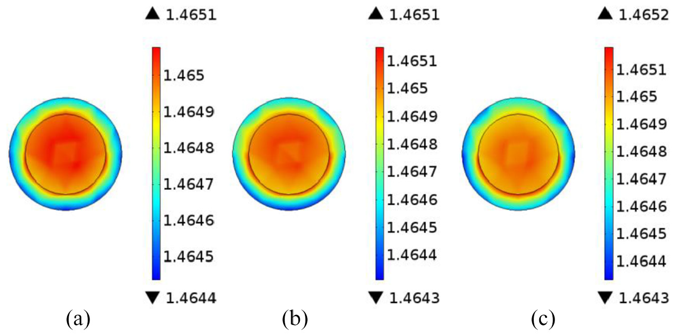
Distribution of refractive index of the embedded fiber at the end of flame spraying: (a) X axis, (b) Y axis, and (c) Z axis.
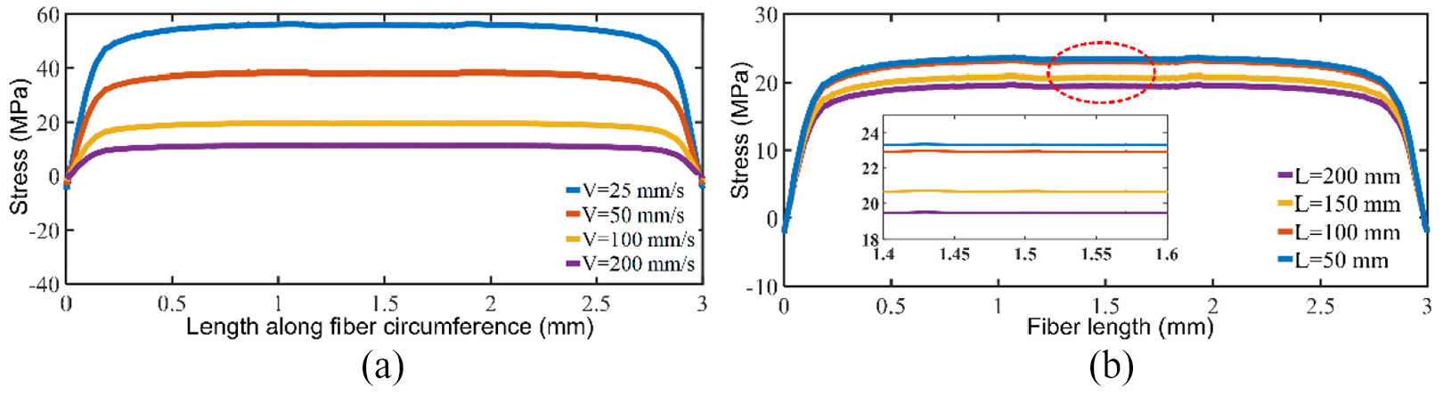
(a) Relationship the stress distribution and the torch velocity and (b) relationship the stress distribution and the torch displacement.
3.4. Refractive index analysis
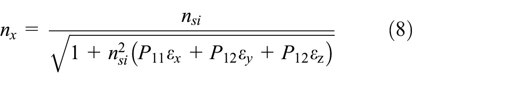
The refractive index is one of the most important parameters which affects greatly the optical property of the embedded fiber optic and the final sensing performances of the smart structure. During the fiber embedding process, the refractive index is modified mainly due to the thermo-optic effect and the elasto-optic effect. In this study, the variation of refractive index due to the thermo-optic effect is ignored, since its variation in function of temperature is insignificant (about 0.13% for temperature variation of 100°). As for the elasto-optic effect, the variation of refractive index in function of fiber strain is expressed as (Bichler et al., 2012)
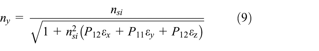
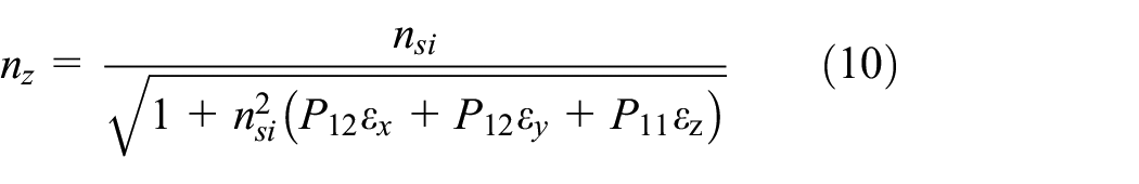
where
4. Modeling results and analyses
4.1. Temperature evolution
First, the thermal result is discussed. Figure 4(a) represents the temperature distribution of the composite structure at the end of flame spraying. Clearly, the coating part which covers the fiber shows the highest temperature of 351.97 K. However, the temperature distribution of the whole composite is almost uniform with the gradient of only 0.28 K. Then, the central point of the embedded fiber is selected and its temperature evolution trace is shown in Figure 4(b); it is seen that the fiber reaches the thermal equilibrium at the end of flame spraying, and then it reduces to the ambient temperature at the end of pure cooling with the continuous forced convection air stream.
4.2. Stress distribution of the embedded fiber optic
Next, the stress distribution of the fiber optic cross section is analyzed, and the end face of the fiber is focused, since it is more likely to be damaged than the inner body of the fiber. The results are shown in Figure 5, “Y axis” represents the horizontal direction and “Z axis” represents the vertical direction of the cross-sectional area. At the end of flame spraying (Figure 5(a) and (b)), it is observed that the strong stress amplitude occurs around the metal protective coating, and it suffers from the strongest tensile stress on both left and right sides in the horizontal direction, while in the vertical direction, the obvious tensile stress is found at the bottom. This phenomenon is reasonable, since the interface the metal protective coating and the optical cladding generates the strongest thermal stress due to the difference of thermal expansion coefficients of the different materials, and these stresses are most likely to affect the fiber geometrical structure. As for the fiber core and the optical cladding, they both suffer from the tensile thermal stress but the stress amplitudes are relatively weak due to the similar material components the fiber core and the optical cladding.
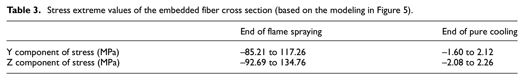
At the end of pure cooling (Figure 5(c) and (d)), the tensile-compressive state of the embedded fiber shows an opposite tendency due to the inverse of the temperature gradient; however, the stress amplitudes become weak. Table 3 summarizes the extreme stress amplitude values of the embedded fiber in the cross-sectional area, and the order of magnitude is 108 (∼100 MPa) at the end of flame spraying, while it decreases to 106 (∼1 MPa) at the end of pure cooling, and the strongest stress amplitude is 134.76 MPa, which occurs at the end of flame spraying.
Stress extreme values of the embedded fiber cross section (based on the modeling in Figure 5).
Next, the stress distribution along the embedded fiber length is analyzed and the result is shown in Figure 6. The interface the optical cladding and the metal protective coating is selected, since it suffers from the strongest thermal stress in the cross section. At the end of flame spraying, it is observed that the stress varies slowly along the fiber length especially for the center part, and the stress amplitudes of the two ends tend to zero due to the settings of the boundary conditions. The average stress value along the fiber length is estimated at 84.85 MPa. Besides, at the end of pure cooling, the stress along the fiber length inverse to the compressive state, and the stress amplitude become much weaker with the average stress value of −1.57 MPa.
From Figures 5 and 6, it is concluded that the fiber always suffers from the strongest tensile thermal stress at the end of flame spraying. Besides, the maximal stress amplitude in the cross section (134.76 MPa) is larger than along the fiber length (84.85 MPa). This phenomenon may be explained by the dimension design of the composite structure; specifically speaking, the substrate length is designed larger than its width. However, the theoretical ultimate tensile strength of the optical fiber is about 689 MPa, which is much larger than the maximum thermal stress values of the fiber in this modeling. Since the incident heat flux which initializes the thermo-mechanical modeling is obtained from the experimental thermogram of flame spraying process, we conclude that the embedded fiber optic is able to ensure good structural integrity under the presented elaboration conditions (Table 1).
4.3. Refractive index variation of the embedded fiber optic
Actually, the refractive indexes of the fiber core and the optical cladding are different, they vary from 1.4 to 1.6, and it exists a minor difference of 1%–2% them due to the different doping materials. In this study, an approximate analysis is conducted. The initial refractive index is set as 1.465 for both fiber core and optical cladding in order to compare them together. Under this condition, the comparison of absolute values is meaningless, and only the relative variation of refractive index during the fiber embedding process is discussed.
The results of refractive index distribution of the embedded fiber at the end of the flame spraying process are shown in Figure 7. It is observed that the refractive index evolves in almost the same manner in X, Y, and Z axes. The refractive index of the fiber core shows a slight rise, and the maximum variation rate is (1.4652 − 1.465)/1.465 = 0.013%. However, the refractive index of the optical cladding shows a decrease, and the maximum variation rate is (1.465 − 1.4643)/1.465 = 0.048%, which situates at the outer edge of the optical cladding. These results signify that the variation of refractive index of the whole fiber (fiber core and optical cladding) is insignificant with the presented elaboration conditions, and therefore the transmission and the sensing properties of the embedded fiber optic are ensured.
4.4. Optimizations of the elaboration conditions
In the second study, the torch movement path is added into consideration, and the stress distribution along the embedded fiber length at the end of flame spraying is evaluated to find out the optimized elaboration conditions; the results are indicated in Figure 8. In the first comparative study, it is observed that the average tensile stress amplitude decreases with the increase in torch velocity, and the minimum stress amplitude becomes less than 10 MPa with torch velocity of 200 mm/s. Then, in the second comparative study, the average tensile stress amplitude increases with the decrease in torch displacement, and the maximum tensile stress is about 23.3 MPa with torch displacement of 50 mm. Besides, similar to Figure 6, the stress at the two end faces of the fiber tends to zero due to the setting of the mechanical boundary conditions.
From Figure 8, several conclusions are obtained. (1) More thermal energies are accumulated in the embedded fiber either when the torch moves with lower velocity or when the torch displacement becomes shorter. Under this condition, the thermal energies transfer as the thermal load and finally generate larger thermal stress. Considering the fiber embedding process, the thermal stress is desired to be as lower as possible, and therefore longer torch displacement and larger torch velocity are needed. (2) When the torch displacement varies from 50 to 200 mm, the variation of the thermal stress equals to 23.3 − 19.5 = 3.8 MPa, which is insignificant when compared with the ultimate tensile strength of silica fiber (689 MPa). It means that the torch displacement has an insignificant effect on thermal stress accumulation. (3) However, when the torch velocity varies from 200 to 50 mm/s, the corresponding average thermal stresses are 11.2 and 38.1 MPa, which is about 3.40 times (38.1/11.2 = 3.40). When compared with (2), it is obvious that the variation rate of thermal stress caused by the torch velocity is larger than that caused by the torch displacement.
5. Conclusion
This study evaluates the overall effects of the flame spraying process and the deposited coating on the structural and optical properties of the embedded fiber optic based on a 3D finite element model, several conclusions are indicated below:
The embedded fiber suffers from the strongest thermal stress at the end of flame spraying. The maximal stress amplitude is 134.76 MPa in the radial direction and 84.85 MPa in the axial direction. Both stress levels are much lower than the theoretical ultimate tensile strength of 689 MPa. Since the incident average heat flux density which initializes the 3D thermo-mechanical model is obtained based on the experimental thermogram recordings of flame spraying, we conclude that the given flame spraying process will not damage the structural integrity of the fiber with the presented elaboration conditions.
During the flame spraying process, the variation rate of maximum refractive index of the fiber core/cladding is estimated as 0.048%. These results signify that the variation of refractive index is insignificant under the presented elaboration conditions, and therefore the transmission and the sensing performances of the embedded fiber optic can be ensured.
Longer torch displacement and higher torch velocity tend to generate less thermal stress in the embedded fiber optic, which is desired for the fiber embedment. Besides, the variation of thermal stress caused by the torch velocity is significantly larger than that caused by the torch displacement.
It should be explained that all the results and the analyses of the modeling are based on the experimental elaboration parameters shown in Table 1. Hence, this study provides an effective method to evaluate quantitatively the effects of actual flame spraying process on the structural property and the optical property of the embedded fiber optic, which lays a good foundation for the experimental fabrications of the flame spraying coating–based fiber composite structure.
Footnotes
Declaration of conflicting interests
The author(s) declared no potential conflicts of interest with respect to the research, authorship, and/or publication of this article.
Funding
The author(s) disclosed receipt of the following financial support for the research, authorship, and/or publication of this article: This work was funded by the National Natural Science Foundation of China (Grant No. 51808347) and Natural Science Foundation of SZU (Grant Nos. 2019109, 860-000002110218).