
Abstract
The wall-slip effect is observed in areas with magnetorheological fluids (MRFs). A slip layer is formed, which reduces the friction between the solid particles and working surface that causes relative movement of the particles. This leads to errors in the measurement of rheological parameters and an inaccurate braking torque model. Thus, here, a rheometer with a sandpaper on the rotor is used to change the working surface roughness to analyze the wall-slip effect of the MRFs. Based on the experimental results, the influence patterns of wall-slip effect on fluid viscosity and yield stress are obtained. Furthermore, a MRF model is established that considers wall-slip effect, which is different from the conventional models. The model is employed to establish a magnetorheological (MR) braking torque model. To verify the braking torque model, a prototype was manufactured, and its mechanical properties were tested. When compared with a smooth rotor, the braking torque of MR brakes with rectangular grooves is increased. This confirms the existence of the wall-slip effect and shows that the wall-slip effect of MRF can be effectively suppressed by incorporating grooves on the rotor surface.
1 Introduction
Recently, the wall-slip phenomenon in the magnetorheological (MR) property tests and engineering applications of magnetorheological fluids (MRFs) has attracted academic attention worldwide. Numerous studies have been conducted on the mechanism and rheological effect of the wall-slip phenomenon. For example, the causes of wall slip, which involve complex liquids, were studied (Ya Malkin and Patlazhan, 2018). The reason for the wall-slip phenomenon and its calculation method and influence on the shear properties were systematically described. The results emphasise that the form of slip layer is related to the shear velocity (Kalyon, 2005). Furthermore, the wall-slip phenomena of ionic and kerosene based MRFs with smooth and rough surfaces were studied, and the effect of the formation of slip layer on the viscosity and shear stress under smooth surface testing was characterised (Gómez-Ramírez et al., 2012). A formula for calculating the thickness of slip layer was proposed, which provides theoretical basis for related studies (Buscall et al., 1993). Considering that the wall-slip effect reduces the test value of shear stress when compared to the actual value, a neuron algorithm was used to compensate for the experimental error caused by wall slip (Chin et al., 2018). The calculation of the force between magnetic particles, and the wall surface was analysed using the theory of magnetic mirror (Lemaire et al., 1991).
In addition, according to the wall characteristics of different structures and materials, several studies were conducted on the wall-slip characteristics of the MRFs. Based on MCR301 rotary rheometer, the rheological effect of MRF was studied with rotors of different materials and wall roughness. It was found that for a non-magnetic disc, a rough wall can significantly increase the measured value of the MRF yield stress, and the yield stress measured under smooth magnetic wall condition was larger than that under smooth non-magnetic wall conditions (Jonkkari et al., 2012). To suppress the wall-slip effect and improve the measurement accuracy of the yield stress of MRFs, measuring plates with different groove shapes were manufactured. The experimental results show that the groove shape and groove width have little effect on the groove shape, but the measured yield stress increases with an increase in groove density. The groove depth was 0.3 mm after optimisation (Tian et al., 2017). The shear stress of MRFs under a magnetic field was measured by magnetic and non-magnetic rotors. According to the magnetic field distribution of different materials of rotors, it was proposed that surface grooves can change shear properties (Laun et al., 2011). The pressure drop of MRFs passing through an aluminum or a steel plate groove was studied (Kavlicoglu et al., 2011). The results show that the width of the aluminum plate groove has little effect on the pressure difference, but the groove depth considerably affects the pressure difference. The wall roughness of steel plate has little effect on the pressure difference, but the pressure difference can be significantly increased after the groove is machined on the wall. To study the effect of magnetic field on the shear instability of MRFs, a rheometer with rough parallel plate geometry was used to measure the shear flow in the controlled rate mode (López-López et al., 2013). It was inferred from the results that the shear instability was mainly due to the periodic failure and healing of the particle structure induced by the magnetic field. The stick slip motion of MRFs in a simple linear shear mode was experimentally studied (Jiang et al., 2015). The critical shear strain at the beginning of stick slip motion decreased logarithmically with flux intensity. In a specific range, the rate of energy accumulation and release in the process of stick slip motion presented a power-law change of continuous phase viscosity.
Unlike the conventional experimental analysis, some scholars used numerical simulation methods to study the mechanism of wall slip. The relationship between the particle structure and wall under different magnetic field intensities was analysed in detail using the discrete element method (Lagger et al., 2014). It was proposed that the magnetic field distribution is the key to the relationship between the particle structure and wall; three different failure mechanisms of the particle structure were reported. The thermal field and dispersion of magnetic particles in the sliding boundary condition were studied using numerical methods (Hayat et al., 2017). It was proposed that the magnetic wall provides additional magnetic force for the magnetic particles in the carrier fluid and changes the chain state of the particles to influence the shear stress. This explains the cause of particle concentration stratification. The Couette Poisson flow of MRFs through a thin channel was analysed (Kim et al., 2014). A magnetic field dependent double viscosity constitutive model was developed and applied with the Navier wall-slip condition. The possibility of the existence of the eight MFD double viscous flows was studied under four different characteristic conditions of the internal magnetic field structure. The quasi-static shear deformation of magnetic particles in Couette flow of MRF was studied using Stokes’s dynamics simulation (Zhou et al., 2015). It was revealed that larger shear rate of the base fluid results in a larger yield stress. The effects of the magnetisation intensity of the walls and their space distance on the yield stress were also investigated.
Although numerous studies were conducted on the formation mechanism and rheological effect of the wall-slip effect, the wall-slip mechanism has not been systematically elaborated, and the influence on its braking performance has not been systematically studied. Therefore, this study investigates the influence of wall-slip characteristics on the viscosity and yield stress using a MCR302 rheometer to test MRFs under three different volume fractions. This paper systematically reports the wall-slip characteristics of MRFs. According to the wall-slip characteristics and working principle of the MR brake, the braking torque model of the MR brake is established. Furthermore, magnetic field simulation, prototype machining, and performance testing are performed to verify the wall-slip braking torque model.
2. Wall-slip effect experiment
2.1. Experimental preparation
The MCR302 rheometer (as shown in Figure 1) was used to test the wall-slip characteristics of MRFs. It can accurately measure rheological parameters such as viscosity, thixotropy and shear stress. The measuring rotor of the rheometer is a parallel plate rotor. When compared with a cone plate, using plate can maximise the contact area between the MRF and plate, thereby increasing the reliability of the experimental results. Under different shear rates, the torque can be obtained when the parallel plate rotor is in contact with the MRF; the required rheological parameters can then be obtained via conversion. The corresponding excitation coils under the magnetic fluid measurement area can produce a uniform magnetic field. A temperature probe and water bath module were installed to accurately control the temperature and magnetic field strength of the magnetic fluid measurement, thereby ensuring the accuracy of the measurement results.
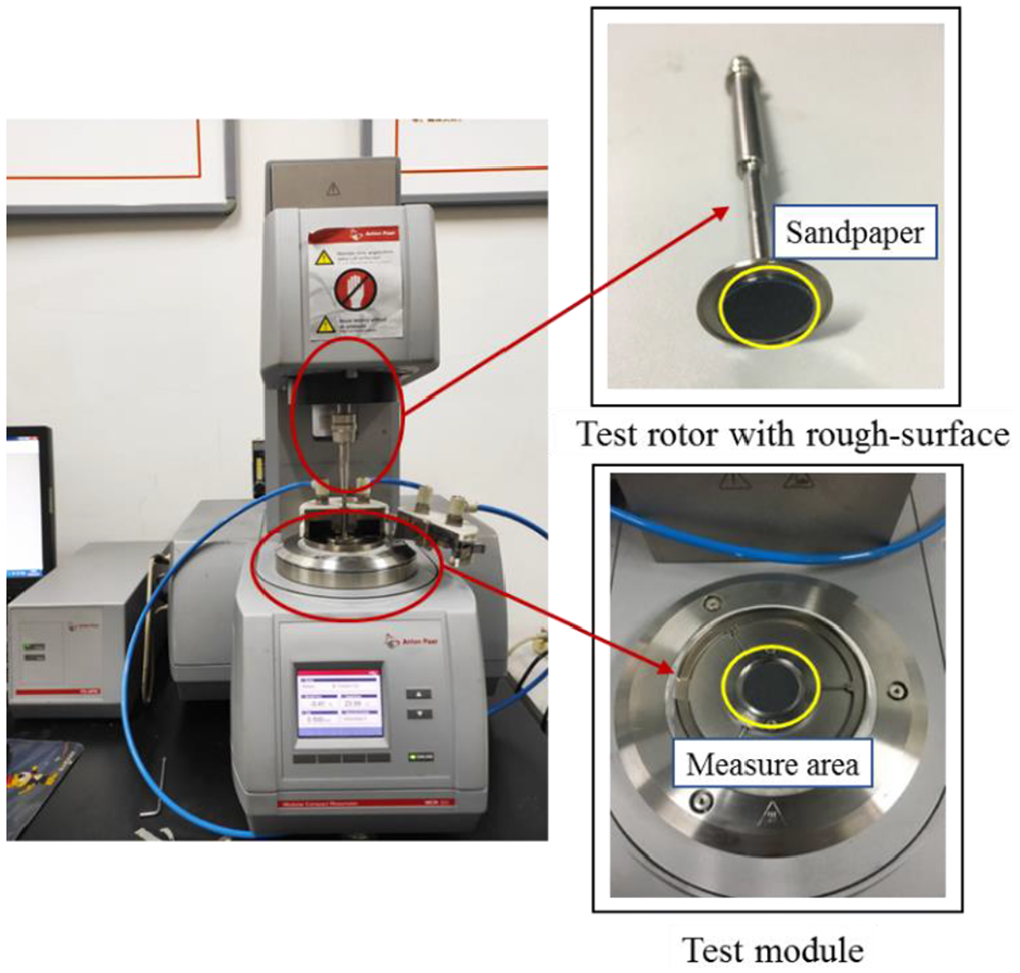
MCR302 rheometer measuring device.
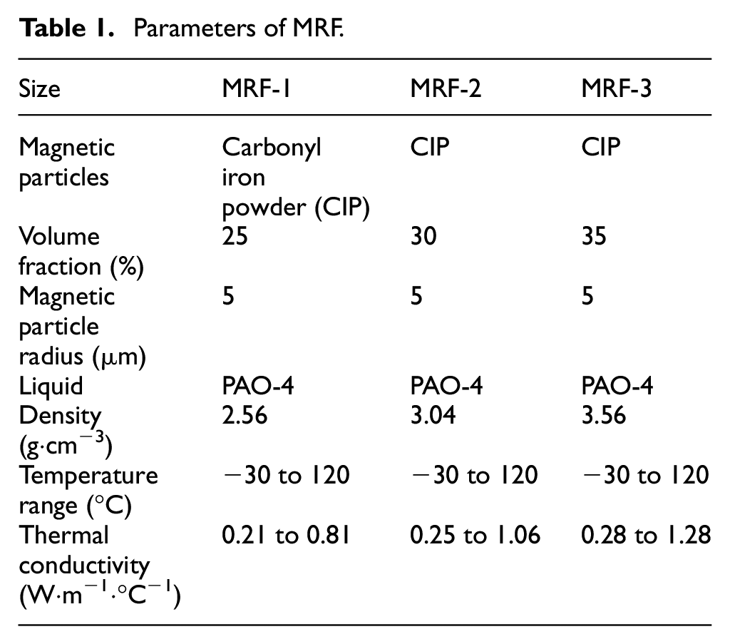
To study the influence of the volume fraction of magnetic particles on the wall-slip effect, three groups of MRFs with different volume fractions of magnetic particles were selected for the experiment. The type of MRF was GH-MRF-35, which was sourced from Beijing HaoHua Technology Limited Company. The selected MRF exhibits good sedimentation stability and wide working temperature range; its main parameters are listed in Table 1. Magnetic particles with a diameter of 5
Parameters of MRF.
2.2. Experimental results
Figure 2 shows the zero-field viscosity measured by rotors with different surface structures. As shown in Figure 2(a), the viscosity of MRF-1 measured by smooth and rough structures was similar. When the shear rate was 0.01 s−1, the deviation was 8.3
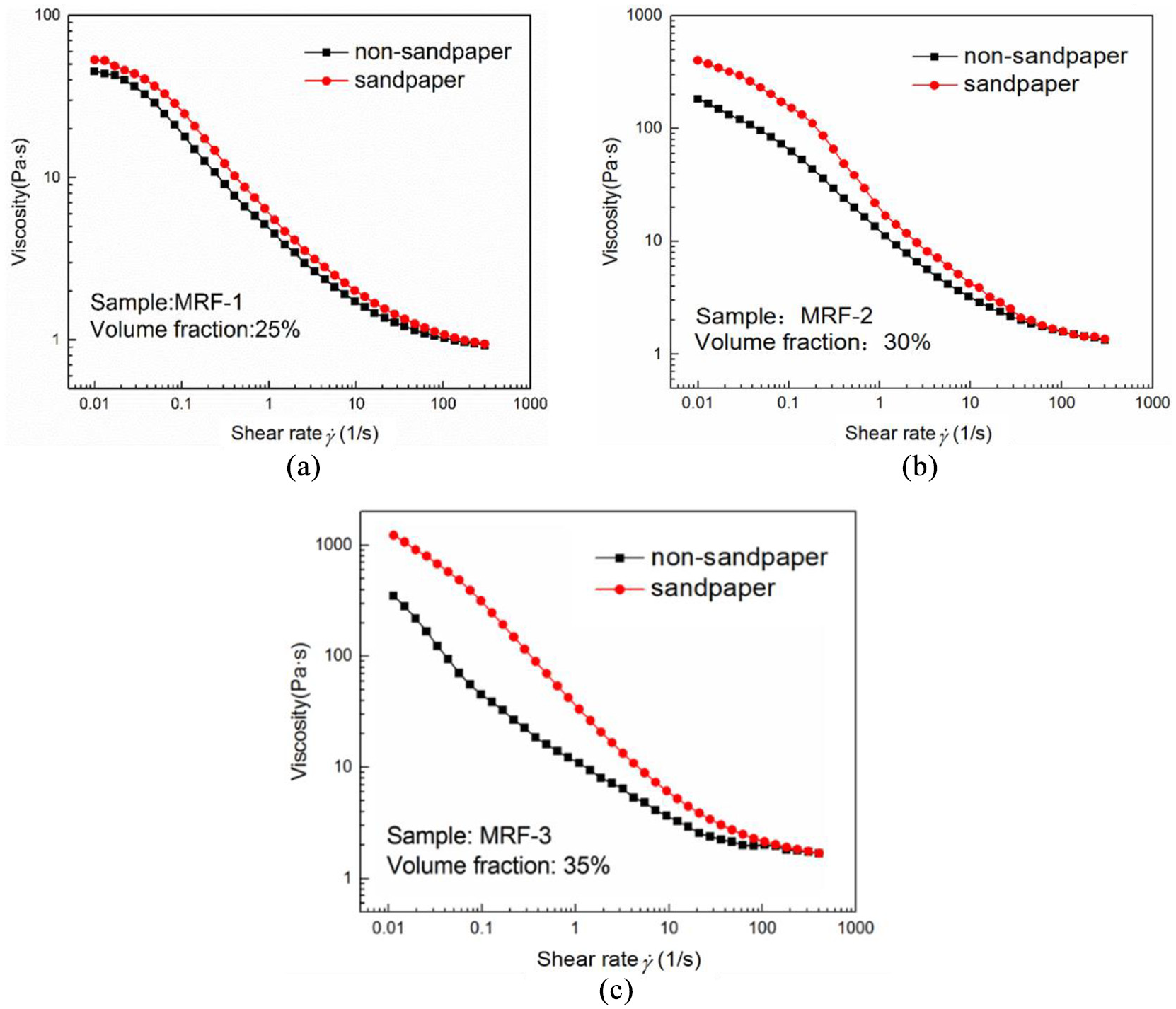
Influence of wall slip on zero-field viscosity: (a) MRF-1, (b) MRF-2 and (c) MRF-3.
The viscosity values measured by rheometer rotors with smooth and rough surfaces when the excitation current increases from 1 to 3 A are shown in Figure 3. The results show that the difference between the viscosity values measured under smooth and rough surface conditions is small, and the wall slip has little effect on the viscosity under a magnetic field.
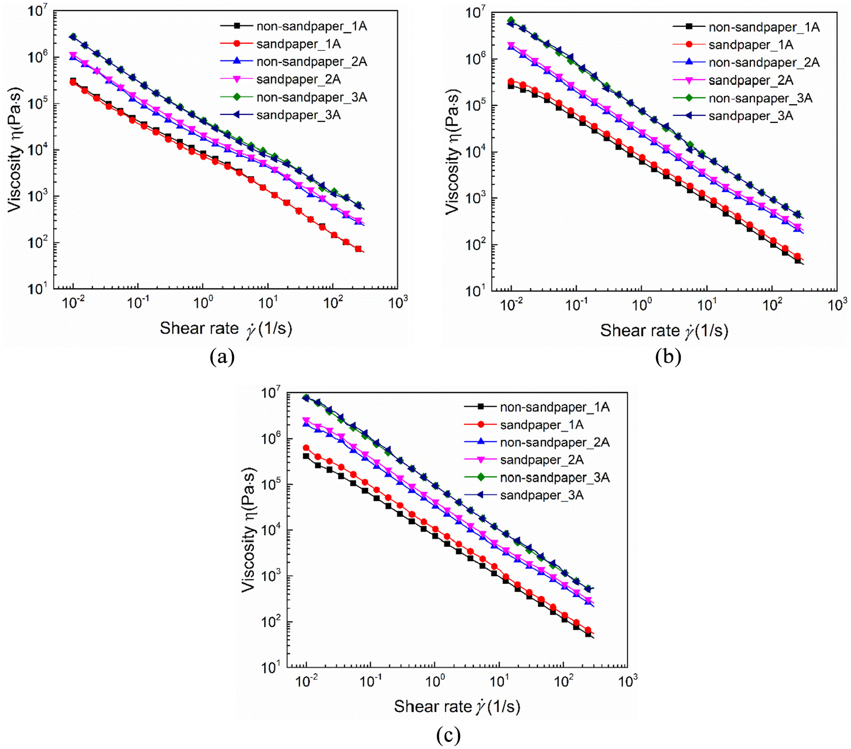
Wall-slip effect on viscosity under different magnetic fields: (a) MRF-1, (b) MRF-2 and (c) MRF-3.
Because the flow characteristics of MRFs without a magnetic field are similar to that of Newtonian fluids, the influence of wall-slip characteristics on yield stress under different magnetic field strengths was mainly studied. The results are shown in Figure 4. For MRF-1, when the excitation current increased from 1 to 3 A, the yield stresses measured by rheometer rotors with different surface structures were similar and the deviations were 0.6, 0.4 and 0.2 kPa, respectively. For MRF-2, the yield stress deviations were 2.7, 0.7 and 0.2 kPa, respectively, when the excitation current increased from 1 to 3 A. For MRF-3, the yield stress deviations were 5.4, 2.7 and 0.5 kPa, respectively. The result shows that the effect of wall slip on the yield stress was negatively correlated with the intensity of magnetic induction.
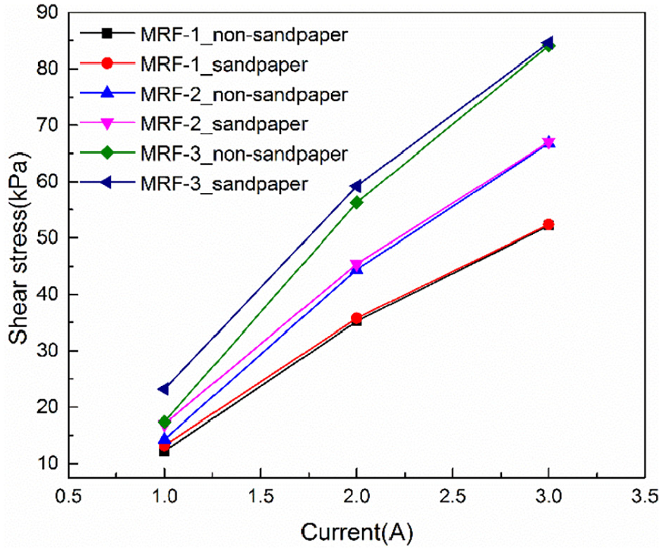
Test results of yield stress.
Based on the experimental study on the wall-slip effect of MRFs, the influence of wall-slip characteristics on the rheological characteristics is described as follows:
In the case of non-magnetic field, the wall slip affects the zero-field viscosity of the MRF. An increase in the volume fraction increases the effect of wall slip on the zero-field viscosity.
In the case of magnetic field, the wall slip has little effect on the viscosity under different magnetic fields but affects the yield stress. Its influence is related to the volume fraction and magnetic induction strength. For the same volume fraction, an increase in the magnetic induction intensity decreases the influence of wall-slip effect on the yield stress. For the same magnetic induction strength, an increase in the volume fraction increases the influence of wall-slip effect on the yield stress.
3. Theoretical analysis of wall slip
3.1. Wall-slip mechanism
The aforementioned experiment results show that the wall-slip phenomenon of MRF has a significant impact on the viscosity and yield stress. Considering the special wall-slip characteristics, the model analysis of the wall-slip mechanism and establishment of the wall-slip model are presented below.
The surface stability of MRF is represented by plane wave perturbation (Li, 2003):
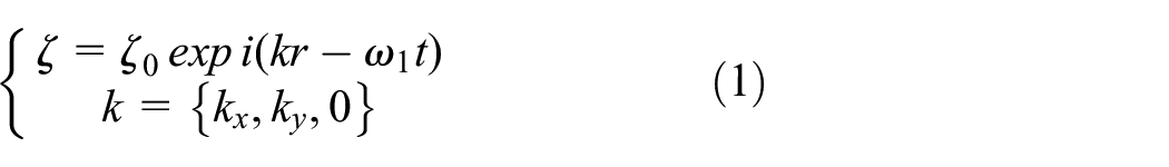
where
When the MRF was in a uniform magnetic field, the dispersion equation was obtained by combining the frequency and number of plane waves propagating on the surface:
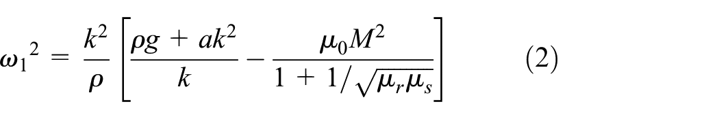
where a is a constant,
Equation (2) shows that when M is sufficiently large, the value on the right-hand side of the equation can be negative. Here, the plane wave propagation frequency was negative, and the liquid level began to become unstable. Therefore, the criterion of surface instability is obtained as follows:
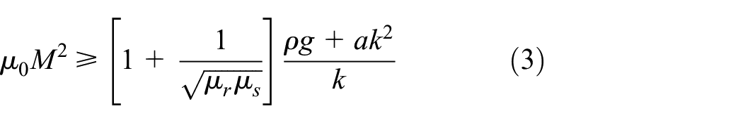
The critical value
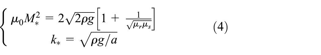
where
The above derivation demonstrates that when the magnetic field is sufficient and the MRF surface is unstable, the original smooth liquid surface changes into a rough surface and forms a needle-like protrusion. Because the magnetic particle chain under the action of magnetic field produces a normal force to puncture the liquid surface, when the magnetic field intensity increases, the number of needle-like protrusions increases and the needle tip becomes higher. When the rotor was used to measure the rheological parameters, the needle-shaped protrusion formed by the action of the magnetic field destroyed the slip layer between the solid boundary and MRF. The smooth liquid surface formed a rough surface, which can suppress the wall-slip effect.
3.2. Wall-slip model
The flow velocity distribution when the wall-slip effect occurs is shown in Figure 5. Because the measurement gap was small, it can be assumed that the velocity of the MRF in the measurement gap presents a linear distribution, and the upper and lower surfaces exhibit a linear distribution. Simultaneously, the thickness of the wall-slip layer was equal.
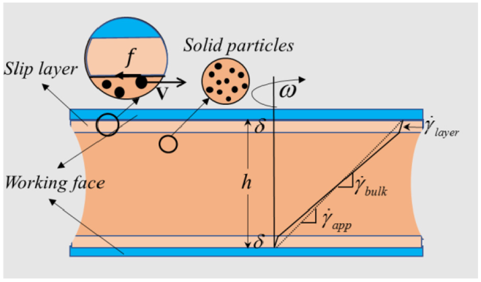
Flow velocity distribution diagram.
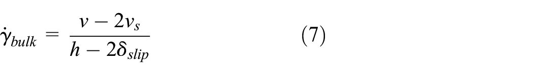
The apparent shear rate value
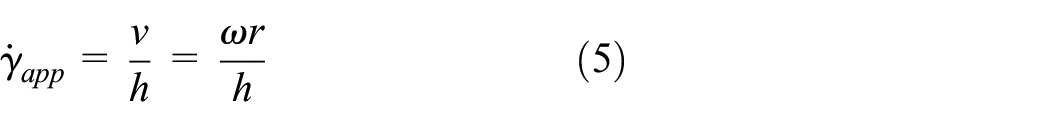
where
The shear rate
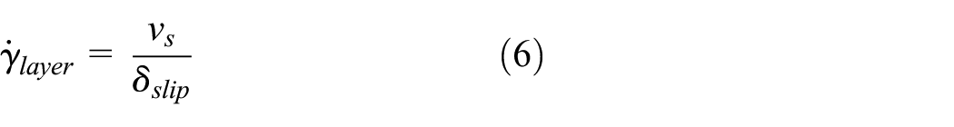
where
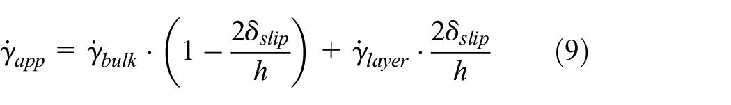
Considering the existence of the upper and lower slip layers, the shear rate
Then, we obtain the relationship between the rates of each layer as follows:

By substituting equation (5) in equation (8), the relationship between the shear rates of each layer can be obtained as follows:
According to Newton’s law of internal friction, the relationship between shear rate, shear stress and viscosity is as follows:
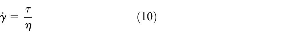
To simplify the calculation, it was assumed that the shear stress within a given radius is uniformly distributed:
where
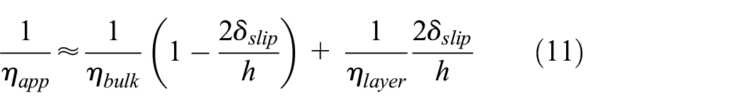
To calculate the solid particle suspension layer thickness formed by the wall-slip effect, several publications have reported empirical formulas, and MRFs are also applicable as a suspension (Korhonen et al., 2015):
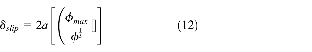
where
By substituting equation (12) in equation (11), the true viscosity of the MRF can be obtained as follows:
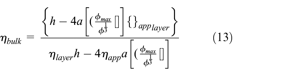
According to equation (13), the influence factors of wall-slip effect on the zero-field viscosity are related to the volume fraction and radius of magnetic particles which are directly proportional to the volume fraction and inversely proportional to the radius of particles.
In general, the relationship between yield stress and magnetic induction strength of MRF is as follows (Sidpara et al., 2009):

where
To obtain the mathematical expressions of yield stress and magnetic induction intensity under the condition of wall slip, the relationship curves of yield stress and magnetic induction strength are fitted using polynomial fitting according to equation (14), and the following formulas are obtained:


The above derivation shows that the wall-slip effect causes errors in the measurement of rheological parameters, which leads to inaccuracy in the engineering application of MRFs. To solve this problem, based on the proposed mechanism and model of wall-slip characteristics, a MR brake with grooves on the surface of the rotor disc was designed, and a wall-slip torque model of the brake was established by combining the conventional brake model.
4. Torque model of MR brake
According to the wall-slip effect on the viscosity and yield stress, a new braking torque model is established by combining the wall-slip characteristics with the braking principle. To study the wall-slip effect on MR brake, the braking torque under wall-slip effect was tested. The method of incorporating rectangular grooves on the surface of the rotor disc was selected to suppress the wall-slip effect (Cloitre et al., 2017). The braking torque test under different operation conditions was conducted with the rotor disc, and the test results were analysed to verify the correctness of the braking torque model.
The investigated brake is a double disc MR brake, which is applied to suppress the wall-slip effect by machining rectangular grooves on the rotor disc surface. The brake structure is shown in Figure 6 (Huang et al., 2018).
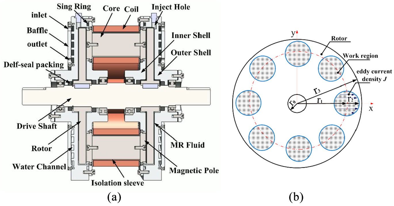
Brake structure diagram and working gap diagram: (a) structure diagram and (b) working gap diagram.
To analyse the wall-slip effect on braking torque, it was assumed that the thickness of wall-slip layer in the working gap was the same, and the velocity distribution in the working area was uniform linear distribution before modelling.
Considering the wall-slip effect on the yield stress, the polynomial fitting method was used to fit the actual yield stress:
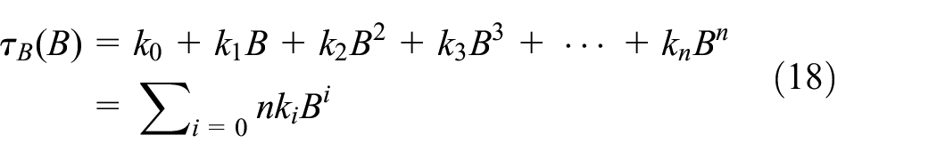
where i is a positive integer and n is a positive integer.
When the magnetic field was applied, the yield stress increases instantaneously, and the braking torque in the region affected by magnetic field can be expressed as follows:
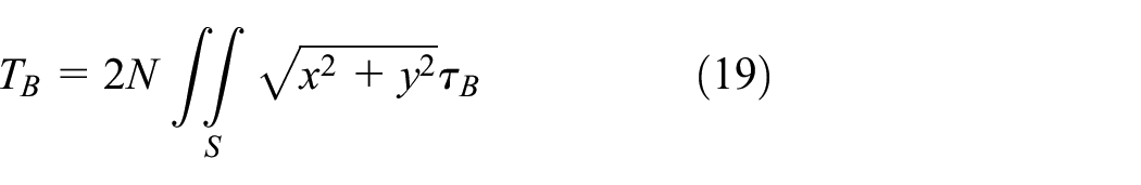
where the integral region S is given by
As
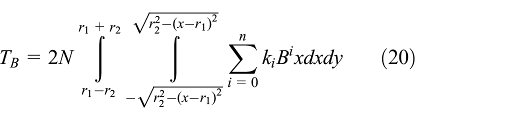
where
To facilitate the calculation,
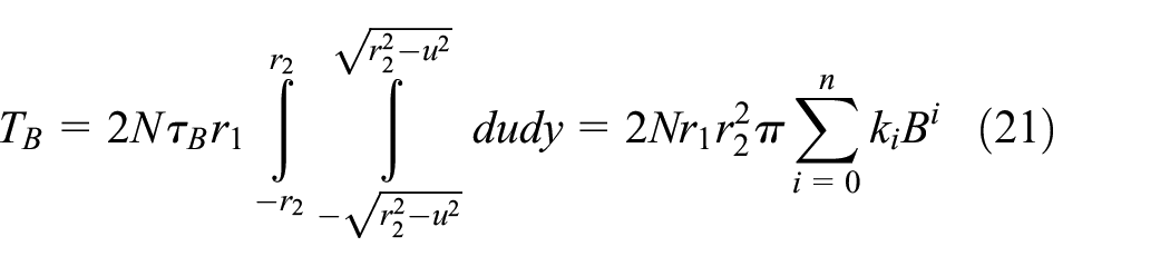
where
Under the magnetic field, the total braking torque produced by the MR brake is as follows:
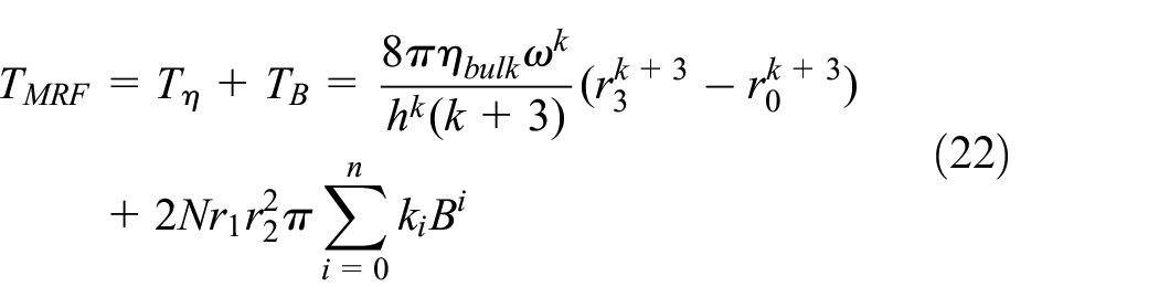
Here,
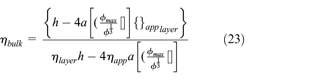
Equations (22) and (23) show that the main sources of braking torque of the MR brake are the eddy current effect, magnetorheological effect and MRF viscosity. According to the influence of the wall-slip effect on the MRF, the relationship between the wall-slip effect and braking torque can be established: when there is no magnetic field, the wall-slip effect of the MRF reduces the braking torque; when the MRF is affected by the magnetic field, the wall-slip effect gradually weakens with the increase of the magnetic induction intensity and when the applied magnetic induction intensity is sufficiently strong, the wall-slip effect can be checked, thereby improving the braking torque.
5. Verification of MR braking torque model
5.1. Prototype of MR brake
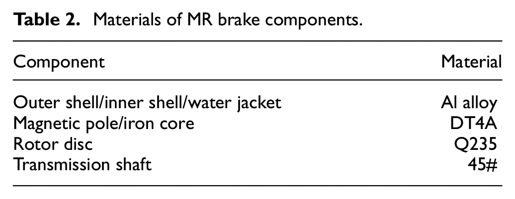
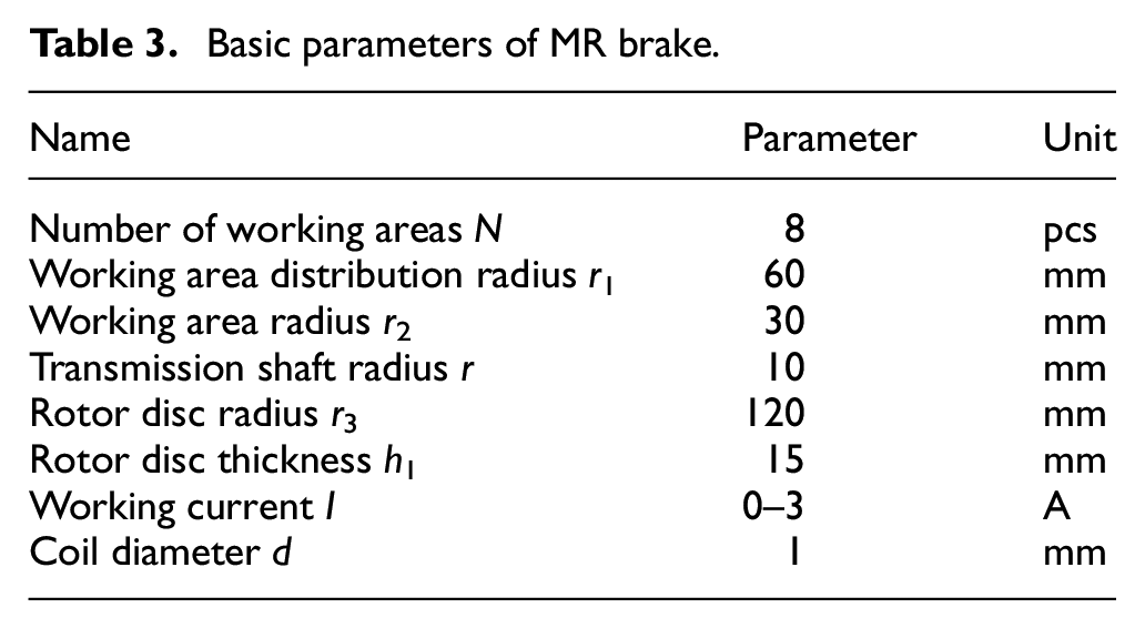
Figure 7(a) presents a rotor disc with machined rectangular grooves, and Figure 7(b) shows a rotor disc without machined grooves. According to the relevant parameters of the MR brake, the image obtained after processing and assembling each part is shown in Figure 8. The weight of the brake is 70.6 kg, and it can withstand retarding braking for up to 12 min under the maximum magnetic field. The main parts of the MR brake are listed in Table 2, and the parameters are listed in Table 3.
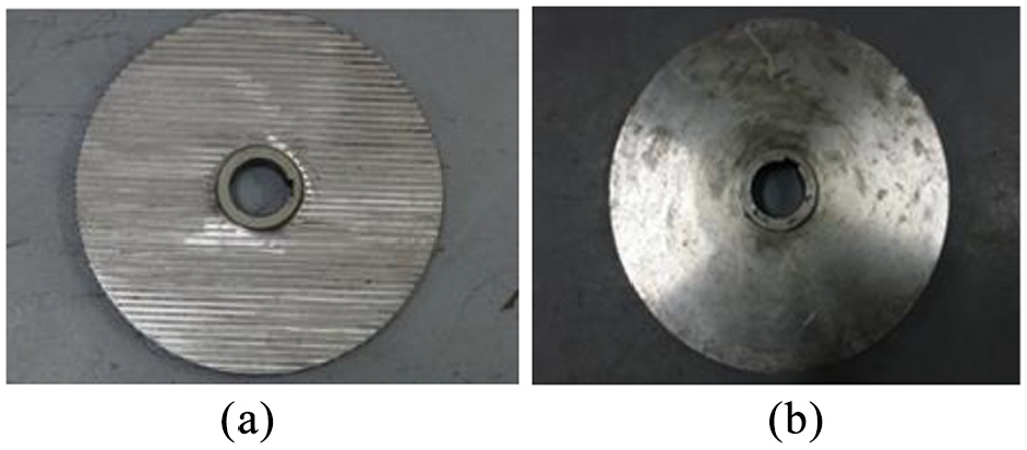
MR brake rotor disc: (a) rectangular grooved rotor disc and (b) smooth rotor disc.
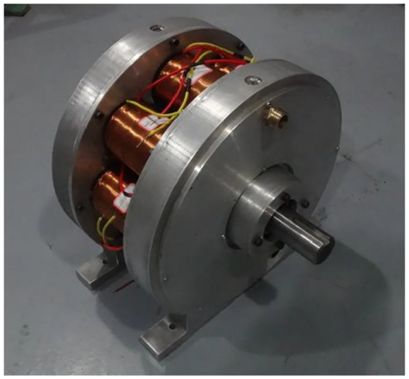
MR brake.
Materials of MR brake components.
Basic parameters of MR brake.
5.2. Construction of performance test platform
Figures 9 and 10 show the schematic and physical diagrams of the MR brake performance test platform, respectively. The platform mainly includes a mechanical braking system, data acquisition and control system and cooling system. The mechanical braking system is the core part of the brake system test bed, and it is mainly composed of a motor, the coupling, a torque sensor and the MR brake. The data acquisition and control system includes a temperature sensor, an acquisition card, an excitation coil control system and a motor control system. The system is used to collect real-time data and control the current excitation coil, motor speed and power. The cooling system is mainly composed of water pumps and water sources.
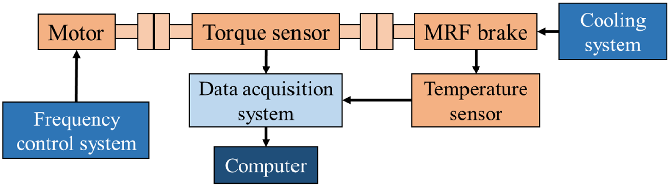
Schematic diagram of brake performance test platform.

Brake performance test platform.
An experiment was conducted to analyse the mechanical properties of the MR brake using the performance test platform. The experiment consists of a no-load torque test and braking torque test. A no-load condition implies that the braking torque changes with the rotation speed when the braking device does not apply an excitation current. A braking force test was used to study the braking performance of the MR brake under different excitation currents and speeds.
6. Experimental results
6.1. Verification of wall-slip braking torque model
The developed torque model was verified experimentally, and the braking torque was tested under no-load condition and an excitation current of 3 A, respectively. Under the no-load condition, three volume fractions were used to test the braking torque at different speeds, and in Figure 11, the results were compared with the theoretical model of wall-slip braking torque. From the analysis results, we can conclude that an increase in the rotational speed slows the rise of theoretical and experimental data. When compared with the experimental volume fraction of 25%, 30% and 35%, the average error between the model and experimental values was 0.98%, 0.62% and 0.74%, respectively. Under the current excitation of 3 A, the average error between the model and experimental data was 1.9%, 2.2% and 2.1%, respectively.
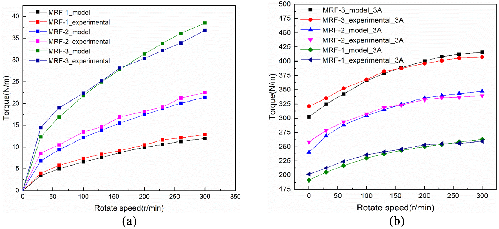
Model validation of speed and braking torque: (a) no-load condition and (b) current excitation of 3 A.
According to the above results, it can be inferred that the wall-slip braking torque model can appropriately predict the torque value of the MR brake under two different working conditions. However, there is a deviation between the theoretical and experimental values. There are two main reason for this deviation. First, the friction between the transmission and seal of the brake, friction between the bearing and sealing ring and friction between the transmission shaft and rotor disc were not considered in the modelling process. Further, the friction of these mechanical structures resulted in a higher measured torque; hence, the theoretical values were smaller than the experimental values. Second, at a current of 3 A, the large excitation magnetic field accelerated the magnetic leakage, and the actual magnetic induction intensity of the coil was less than that of the theoretical value; thus, the theoretical values were higher than the experimental values.
6.2. Analysis of wall-slip suppression effect
To study the braking performance of the MR brake with the rectangular grooved rotor disc and to investigate the effect of wall slip on the MR brake, braking torque test experiments were conducted with different rotor discs. The torque under braking refers to the torque produced by the MR brake when the coil current was 0–3 A. The torque was mainly generated by the magnetorheological effect and eddy current effect. In this study, the braking torque generated by the eddy current part was not investigated, that is, the effect of the rotor disc brake with grooves on the braking torque generated by the sliding part of the wall was not studied.
The braking torque under no-load condition was mainly produced by the zero-field viscosity and mechanical friction of the MRF. To study the braking performance of the MR brake under the no-load condition and the influence of wall slip on the no-load torque, torque test experiments were conducted.
Figure 12 shows the no-load torque curve of three MR brakes with different rotor discs. The test results show that when MRF-1, MRF-2 and MRF-3 were considered as the working fluid, the maximum torque lifting rates were 6.8%, 36.5% and 52.9%, respectively, while the average lifting rates were 2.9%, 9.6% and 17%, respectively. An increase in the volume fraction increases the wall-slip effect on the viscosity. Hence, the inhibition effect on the wall slip becomes significant when using the rotor disc with rectangular grooves. It can be concluded that the MR brake with rectangular grooves can effectively inhibit the wall-slip characteristics under the no-load condition to improve the no-load torque of the MR brake.
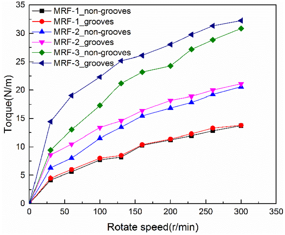
Curve of braking torque varying with rotational speed under no-load condition.
Figure 13 shows the relationship curves between the braking torque and speed of MRF-1 under a current of 1–3 A. As shown in the figure, as the coil excitation current increases, the braking torque deviation of MR brake with different rotor discs decreases gradually. The braking torque is similar under different current conditions with the increase of rotating speed. When the coil excitation current was 1 A, the deviation between the two conditions was the largest, average braking torque lift rate was 1.6% and maximum braking torque lift rate was 6.6%. When the coil excitation current was 2 and 3 A, the braking torque was reduced to 0.5% and 0.2%, respectively. According to the above analysis, the effect of wall slip on braking torque mainly occurs because of two sources: one is the yield stress in the area under magnetic field action, and the other is the zero-field viscosity in the area without magnetic field action. When MRF-1 was used, the wall-slip effect had little influence on its yield stress and zero-field viscosity. The torque measured by the brakes with different rotor discs was similar under different coil current intensities.
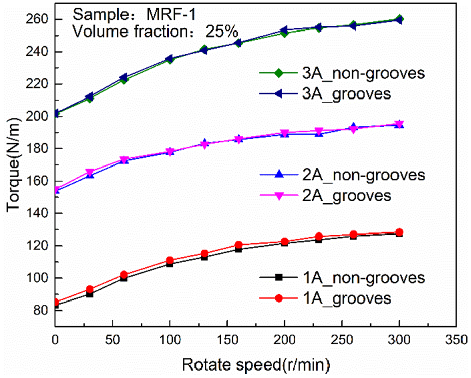
MRF-1 curve of braking torque varying with rotational speed at different current.
Figure 14 shows the relationship curves between the braking torque and speed of MRF-2 under a current of 1–3 A. With an increase in the coil excitation current, the braking torque deviation of MR brakes with different rotor discs decreases gradually. When the coil excitation current was 1 A, the average braking torque lifting rate of the rectangular grooved rotor disc was 4%. When the coil excitation current was 2 and 3 A, the braking torque lifting rate was 2.4% and 0.13%, respectively.
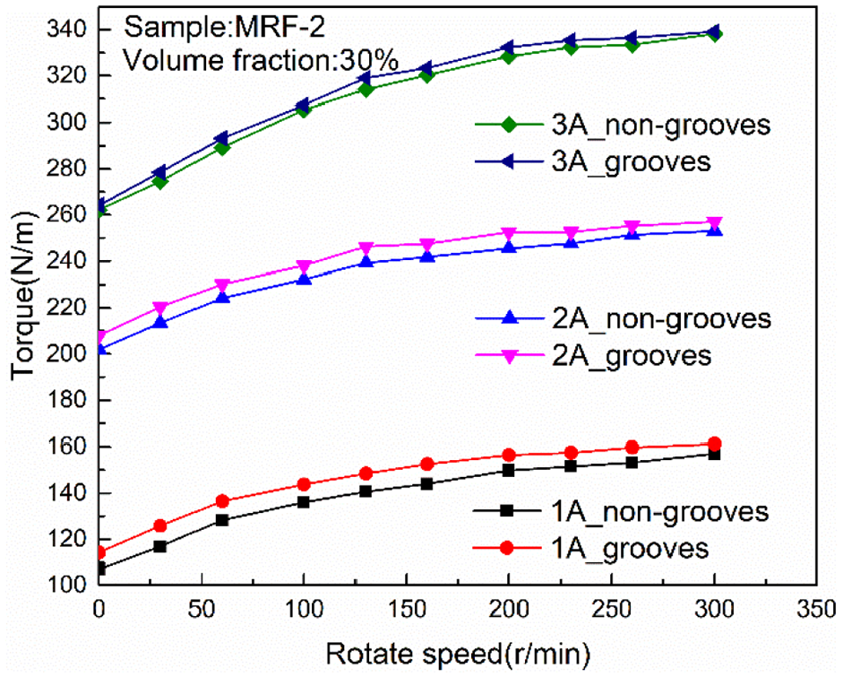
MRF-2 curve of braking torque varying with rotational speed at different current.
Figure 15 shows the relationship between the braking torque and speed of MRF-3 under a current of 1–3 A. When the excitation current was 1, 2 and 3 A, the average braking moment lift rate of the rectangular grooved rotor disc system was 5.2%, 3.3% and 1.6%, respectively, of that of the non-grooved rotor disc system.
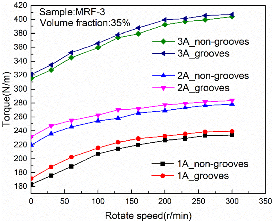
MRF-3 curve of braking torque varying with rotational speed at different current.
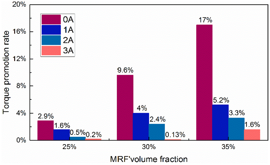
Figure 16 shows the lifting rate histogram of the braking moment of the three volume fractions under different excitation magnetic fields with and without a rectangular fluted ratio. The test results further show the influencing factors of the wall-slip effect and the manner in which it affects the braking performance:
According to the analysis of test results under different MRF volume fractions, when the volume fraction of the MRF increases from 25% to 35%, the impact of wall-slip effect on the maximum average braking moment lift rate is 1.6%, 4% and 5.2%, respectively.
The test results with different current excitation show that under the non-load condition, an increase in the volume fraction produces more significant torque for the MR brake with grooves. When the coil excitation current increases from 1 to 3 A, the average braking moment lift rate of the three types of MRFs decreases from 1.6% to 0.2%, 4% to 0.13% and 5.2% to 1.6%, respectively. The braking torque with the grooved rotor disc under the no-load condition was more evident than that under magnetic field excitation condition. This is because the wall-slip layer of the MRF becomes damaged as the coil excitation current increases. Furthermore, the electromagnetic force and friction force between magnetic particles and the transmission interface increase. Consequently, the difficulty of wall slip increases, and the increased value of the lifting rate becomes smaller.
Average braking moment lift rate of grooves under different conditions.
7. Conclusion
This study verified the effect of the MRF wall-slip effect on the fluid flow parameters. According to the experimental results, a wall-slip characteristic mechanism is proposed herein. A new brake wall-slip torque model was established, and a new MR brake was designed. The existence of wall slip was verified by processing grooves on the rotor disc, which influenced the braking torque. The conclusions of the study are as follows:
According to the experimental study of the wall-slip effect of the MRF, when a magnetic field was absent, the wall slip mainly affects the zero-field viscosity. As the volume fraction increases, the wall-slip effect on the zero-field viscosity of the MRF increases. In the case of magnetic field, the yield stress is mainly affected. The greater the applied magnetic induction intensity, the smaller is the impact of the wall-slip effect on the yield stress. Further, the impact of the wall-slip effect on the yield stress is greater when the volume fraction is greater.
The experimental results show that the MR brake with grooves shows better braking performance than the non-machined MR brake. The wall-slip effect of the MRF with different volume fractions can be effectively inhibited, and the braking torque of the MR brake can be improved.
Footnotes
Declaration of conflicting interests
The authors declared no potential conflicts of interest with respect to the research, authorship, and/or publication of this article.
Funding
The authors disclosed receipt of the following financial support for the research, authorship, and/or publication of this article: This work was supported by Ministry of Science and Technology of the Peoples Republic of China, and subproject of National Key R & D Program, Key Technology of Design and Manufacture of micro high speed on-off valve(Grant No.2019YFB2005103), general project of Natural Science Foundation of Fujian Science and Technology Department (Grant No. 2020J01452), The Key Laboratory of Fluid Power and Intelligent Electro-Hydraulic Control (Fuzhou University), Fujian Province University, the projects from educational research projects for young and middle-aged teachers (Grant No. JAT190007).