
Abstract
In this study, a Magnetic Levitation Energy Harvester (MLEH) was designed and fabricated. The magnetic field distribution and power generation performance of multiple cylindrical magnets were studied. The full factorial design (FFD) of L20 (22 × 5) test was carried out with the sliding magnet arrangement, coil arrangement and wiring method as the control factors, and the output power as target factor. Sweeping-frequency vibration tests and railroad spectrum random vibration tests were conducted to verify the power generation capacity of the prototype. Experimental results show that the device has a broadband response and the railroad vibration test proves the effectiveness of harvester in the application scenario for powering the rail-side sensors. The range of maximum output voltage, power and corresponding frequency in sweeping-frequency vibration tests with the amplitude of 1 to 10 mm and frequency of 5 to 50 Hz are 1.5 to 4.5 V; 1.80 to 17.0 mW and 9.7 to 30.8 Hz. The maximum output voltage and power are 1.33 V and 1.47 mW based on the measured railroad spectrum. Finally, a retrospective review in the efficiency, effectiveness and volume figure of merit is conducted to evaluate the performance of MLEH, indicating a high power density of the proposed harvester.
1. Introduction
Vibration is often accompanied by the operation of machinery, and most vibrations bring side effects and cannot be eliminated. Therefore, collecting and utilizing vibration energy has practical significance in energy saving, environmental protection, and cleaner production (Carneiro et al., 2020; Hou et al., 2020; Li et al., 2018; Shu et al., 2019; Wu et al., 2019). For most machinery or devices, the energy obtained from vibration is insignificant compared to mechanical power sources (such as internal combustion engines and generators), and the feedback of the energy from vibration to the power system is of little significance (Fang et al., 2020; Huang et al., 2020; Li et al., 2019; Zhou and Zuo, 2018). However, components with low power demand such as sensors can be driven by the energy scavenged from vibration (Yang et al., 2019, 2020). The sensor is an indispensable device for status detection and signals feedback of modern mechanical equipment. The development of Micro-Electro-Mechanical System (MEMS) techniques reduces the power consumption of sensors to a milliwatt level, enabling us to supply these low-power sensing devices with the energy harvested from vibrations (Gao et al., 2019, 2020a, 2020b, 2021; Sun et al., 2021).
Railway has many advantages in cargo transport, such as safety, environmental protection, cost-effectiveness, and has become the core transport mode of various countries. Taking China as an example, the total rail freight volume increased from 3.813 billion tons in 2014 to 4.318 billion tons in 2019. In 2018, the number of railroad locomotives in the country reached 21,000, and the number of railway wagons in the country was 833,000 (Chen, 2019). In the railway industry, the working conditions of freight cars cannot be obtained in real-time due to the lack of power supply for sensing devices. It is challenging to power these monitoring devices from the cabin room. Traditional sensors mostly use batteries as a power source, which has shortcomings such as short life cycle, large volume, and pollution issues, and requiring periodical replacements. Therefore, it is beneficial to harvest vibration energy and drive the sensors.
There are many ways to harvest energy from vibration. Common types include piezoelectric (Cha et al., 2016; Erturk et al., 2009; Fan et al., 2018; Kan et al., 2016; Yang et al., 2021; Lai et al., 2021; Wang et al., 2021), electrostatic (Daqaq, 2011; Donelan et al., 2008; Tao et al., 2018; Zhang et al., 2018), electromagnetic (Gao et al., 2018, 2020a), and magnetostriction (Wang and Yuan, 2008). Piezoelectric energy harvesters have high sensitivity and can obtain voltages under small vibrational deformation, but their large internal resistance results in low output power (Lu et al., 2020). Electrostatic energy harvesters are made of expensive electret materials and are not suitable for large-scale promotion at this stage. The magnetostrictive energy harvester has a complicated structure and requires a large volume. Electromagnetic energy harvesters, based on Faraday’s law of induction, have the advantages of high output power and cost-effectiveness and thus electromagnetic harvesters have attracted wide attention (Lu et al., 2021a, 2021b).
Electromagnetic energy harvesters (EMEHs) mainly include mechanical types and magnetic suspension oscillators (Firoozy and Ebrahimi-Nejad, 2020; Firoozy et al., 2019; Yang and Zhou, 2019). The mechanical type mainly transfers the vibration to the motor through a spring or gear, driving the motor for converting mechanical energy to electricity. The mechanical EMEH can obtain the most energy when the excitation frequency is consistent with its natural frequency; and the displacement of the vibration is used to drive the motor to work, which leads to limitations to its fixed position. For magnetic levitation energy harvester (MLEH), the non-linear characteristic of the repulsive force between the suspension and fixed magnets leads to wider frequency response. Compared with mechanical energy harvesters, MLEHs have higher power output at low frequencies, no special material requirements, and low costs, which can meet the requirements of large-scale application in the field of railway and agricultural machinery industry.
Aldawood et al. (2019) presented an enhanced energy harvester based on magnetic springs, using dual-mass and geometrically non-linear mechanical planar springs to increase the power of the harvester. Nammari and Bardaweel (2017) proposed a type of magneto-mechanical non-linear vibration energy harvester, which used four tilt springs to guide the movement of the suspended magnet. The broadband and low-frequency energy collection characteristics of the designed harvester were verified through experiments. Zhang et al. (2019) proposed a device that integrated a non-linear shock absorber and a suspended magnetoelectric energy harvester, which can effectively reduce vibration while improving energy harvesting capacity. Fan et al. (2019b) achieved a 2-DOF electromagnetic energy harvester (EMEH) by encapsulating 1-DOF EMEH and magnetically suspending it in a cylindrical shell and conducted the experimental investigation. The result indicated that the 2-DOF EMEH could capture ultra-low frequency vibration energy. The above research aimed to realize broadband and low-frequency energy harvesting by improving the design of mechanical structures. However, the presented structure will influence the stability of the unidirectional motion of the suspension magnet due to contact sliding friction between the suspended magnet and the tube, thereby reducing the energy-conversion efficiency.
To meet the power consumption of different sensors and adapt to various working conditions, extensive research has been conducted to increase the output power of magnetic-suspension vibration energy harvesters. Palagummia and Yuan (2018) designed a bistable magnetic levitation system and studied its dynamic model, and verified that the energy harvester could be used under low-frequency (<10 Hz) conditions. Gao et al. (2018) presented a multi-stable electromagnetic-induction energy harvesting system. The bifurcation, high-energy orbit motion, and chaotic motion were experimentally studied. The result indicated that the multi-stable energy harvesting system could significantly improve the energy harvester performance and deliver a remarkable current to loads. Li and Wang (2017) analyzed the effects of damping ratio, frequency, non-linear coefficient, elastic coefficient, and excitation amplitude on the vibration response characteristics, with the vibration energy harvester as the research object of the vibration pickup structure. The physical model and dynamic equations of the vibration sensor structure were established, which contribute to optimizing structures of vibration energy harvesters.
The above research mainly focused on introducing non-linear magnetic restoring force, constructing a bistable or multi-stable mechanism to widen the effective frequency band. The optimization is realized by adjusting the number of sliding magnets, which could be limited in the practical application due to the actual size constraint of the device. The performance of the magnetic levitation electromagnetic energy harvester has a relationship with the winding and arrangement of coils as well as the polarity direction of multiple magnets; however, to the best knowledge of the authors, few studies have been explored from the perspective of coil layout, polarity layout of multi-magnets and wiring under the constraint that the overall size of the device cannot be changed. Besides, most of the existing research methods were carried out in the form of sinusoidal excitation for experimental research; however, the actual ambient vibration is mostly a random broadband power spectrum.
In this study, a suspended electromagnetic energy harvester is presented. Sliding magnets are guided by non-ferromagnetic copper beads, ensuring the unidirectional movement of sliding magnets. The novel contributions and features of the present study include: (1) a broadband and high power density magnetic levitation energy harvester was selected through the FFD method; (2) the influences of the coils layout, wiring modes and magnetic polarity configurations on the output power as well as the broadband and load characteristics of the vibration energy harvester were studied; (3) the actual random vibration signals (measured railroad spectrum) were applied to the vibration energy harvester and the deliverable power and voltage to a resistant load justify the practicality of the proposed device; (4) a comprehensive comparison of the harvester performance is conducted regarding the efficiency, the effectiveness, and the volume figure of merit.
The rest of the paper is organized as follows: the theory, model and power generation of the magnetic field of multiple cylindrical magnets are described in Section 2. Device setups based on FFD methods as well as detailed experimental work of the frequency-sweeping tests, fixed frequency tests, and railroad vibration tests are described in Section 3. Results of theoretical analysis and experiment are compared, and findings and outcomes from model and experiment are included in Section 4.
2. Theory and model
2.1. Magnetic field of the single cylindrical magnet
Consider a cylindrical magnet of length 2b and radius a, as illustrated in Figure 1. The origin of the cylindrical system is located at the center of the magnet. Each point in the cylindrical system can be written as
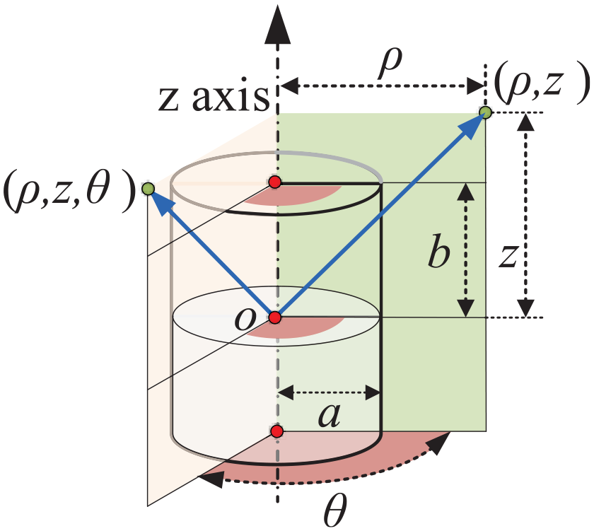
The coordinate system of a cylindrical magnet.
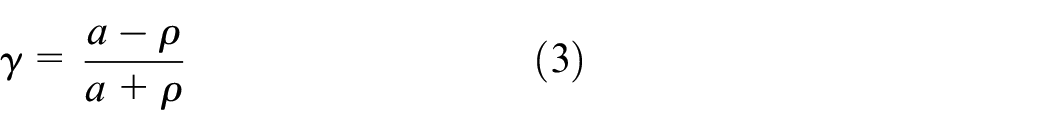
According to the cylindrical symmetry of a cylindrical magnet, the magnetic field is symmetrical to the symmetry axis. The calculation of the magnetic field at point
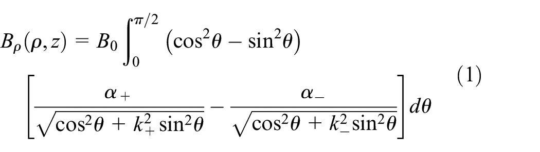
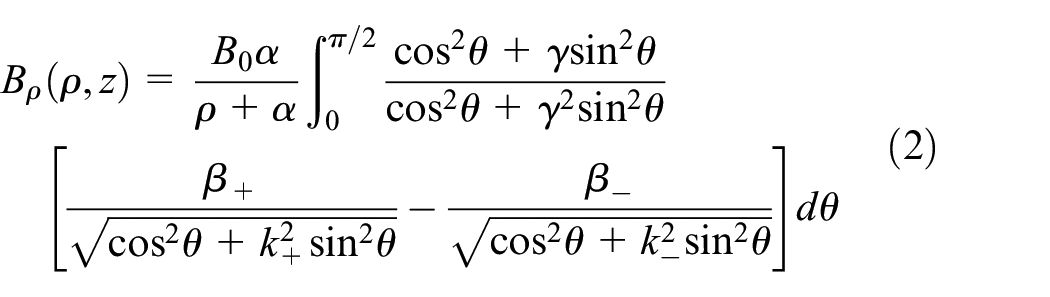
where,
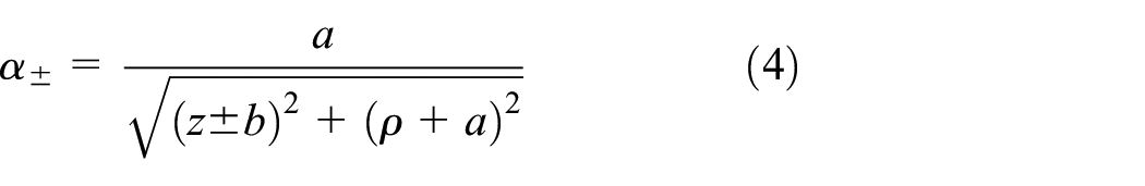
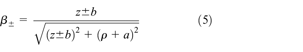
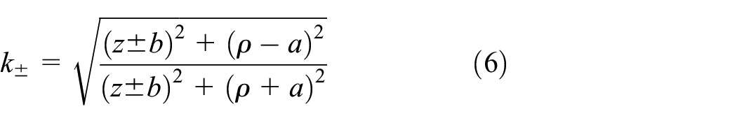
The magnetic field can be numerically calculated according to equations (1) and (2) efficiently.
Under the world coordinate system, a cylindrical magnet can be uniquely specified by a center


where,
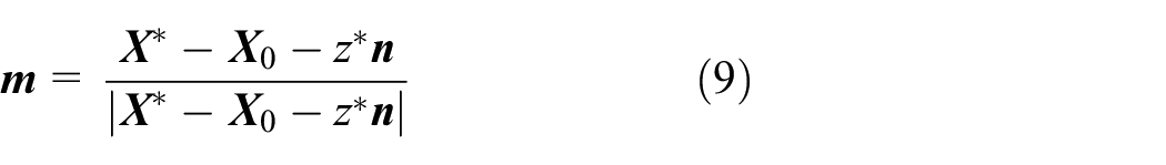
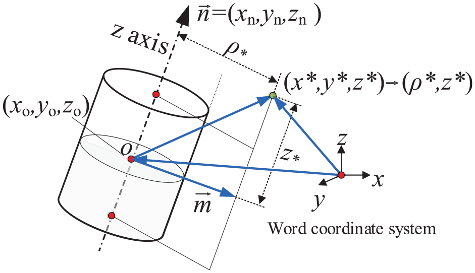
The geometry of a cylindrical magnet in the world coordinate system.
As a result, the magnetic field of X in the world coordinate system can be calculated according to

where,
2.2. Magnetic field and power generation performance of multiple cylindrical magnets
For the magnetic field generated from multiple cylindrical magnets, it can be calculated based on the superposition principle for magnetic fields. Given k magnets with each specified with center
where subscript i indicates the parameter of the i th magnet.
The magnetic field can also be obtained through simulation according to the superposition principle for the magnetic field generated by multiple cylindrical magnets, as shown in Figure 3.
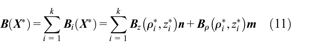
The magnetic flux density of two magnetic pole configurations: (a) the magnetic flux density in the form of A1 (NS-NS-NS) and (b) the magnetic flux density in the form of A2 (NS-SN-NS).
The induced current is proportional to the magnetic flux density with other parameters that are consistent according to Faraday’s law, and magnetic flux density can be measured by the density of the magnetic field line passing through the coil. Sliding magnets can be seen as a unit magnet when arranged as A1, and part of the magnetic field lines enter the magnet, then the maximum magnetic flux density is found at both ends of sliding magnets, as shown in Figure 3(a). When sliding magnets are arranged in the form of A2, the three sliding magnets repel each other so that the magnetic force lines inside the magnet can be squeezed out, then the maximum magnetic flux density is found at the junction of three sliding magnets, as shown in Figure 3(b). The density of magnetic in the form of A2 is larger than A1, as shown in Figure 3.
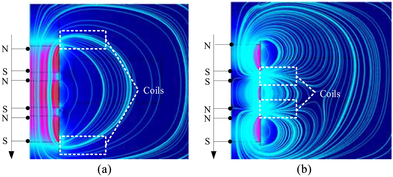
In order to study the power generation performance under different magnetic pole configurations of multiple cylindrical magnets intuitively, a comparative investigation is conducted based on the Finite Element Method (FEM). During simulations, the magnets of the two setups oscillated around their stable points according to the function of
The power generation performance of two magnetic pole configurations: (a) the calculated open-circuit voltage of the two setups, (b) the power generation performance in the form of A1 and (c) the power generation performance in the form of A2.
As shown in Figure 5, the magnetic levitation harvester must be installed outside of the clearance of the train. In our device setup, the maximum quantities of inner floating magnets are three; thus the following design of the experiment is conducted for the triple-magnet configuration, which is following Deutsches Institur fur Normung (DIN) standard 15273-2 (DIN EN 15273-2, 2014).
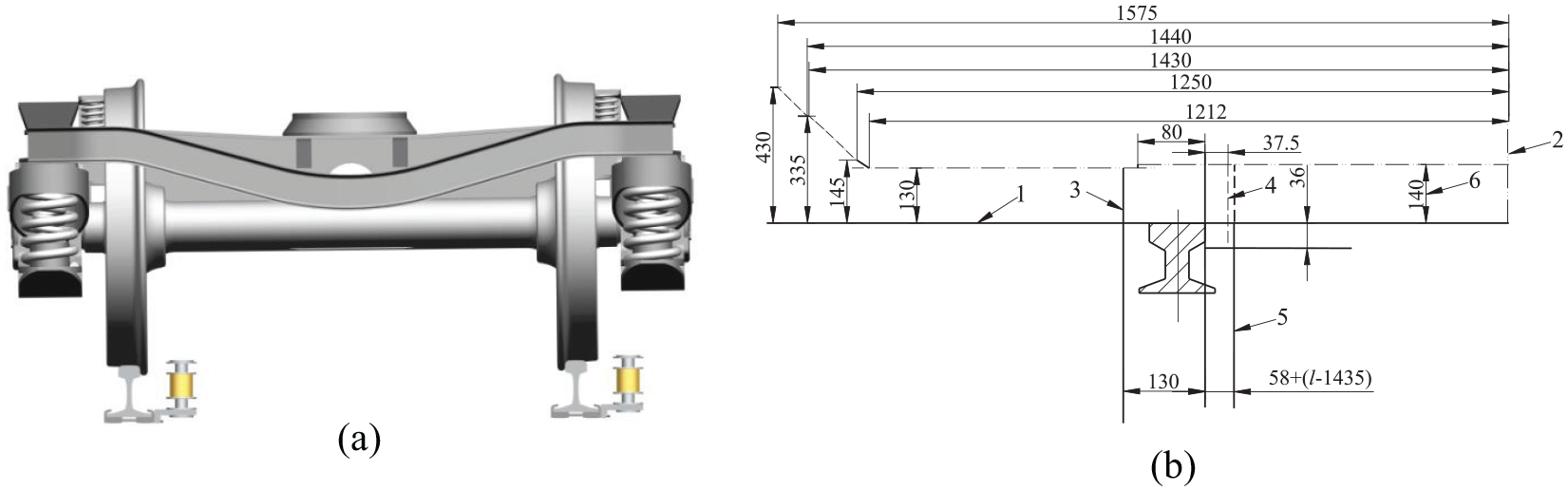
Clearance illustration of magnetic levitation devices: (a) devices setup and (b) rolling stock gauge.
2.3. Magnetic floating and restoring forces
A schematic diagram of the floating magnetic system is shown in Figure 6. The device used two fixed magnets that were mechanically attached to a fixed support. The fixed supports were also rigidly connected to the cylinder housing. Sliding magnets were placed between the two fixed magnets, and the magnetic poles were oriented to repel the center magnet—thus suspending the sliding magnets with a nonlinear restoring force. Here, we emphasize a paradigm shift by noting that nonlinearity is an integral feature of the energy harvester design. In particular, it will be shown that nonlinearity allows the linear resonance to be tuned by simply changing the spacing between the upper and lower magnets.
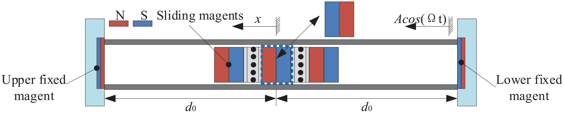
Schematic diagram of the floating magnetic system.
According to the investigation of Mann (Mann and Sims, 2009), restoring forces acting on the upper (FU) and lower fixed magnet (FL) are obtained by the following formulas:
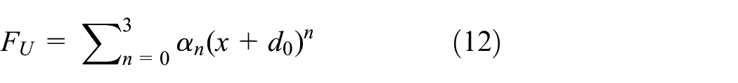
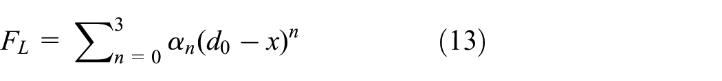
where d0 is the relative space between the upper/lower magnet and sliding magnets in a static equilibrium state in Figure 6.
The total restoring force Fx is given by a vector summation of the restoring forces from the upper and lower fixed magnets, and its equation is as follows:

Substituting into equations (12) and (13), then:
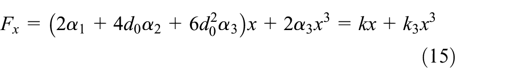
where the coefficients α1 to α3 are obtained using a least-squares procedure from the curve data in Figure 7. d0 is the the distance between centers of the sliding magnet and fix magnets, as shown in Figure 6. k is the linear stiffness coefficient and
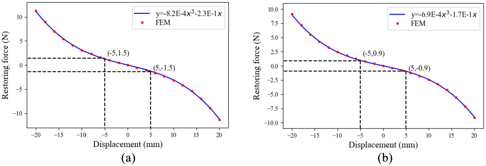
The restoring force of two magnetic pole configurations: (a) the restoring force of form A1 and (b) the restoring force of form A2.
Figure 7 shows the restoring force of sliding magnets plotted as a function of the separation distance between two magnets (Fan et al., 2019a). Generally, the restoring force is directed back toward the stable point of the system, and it can be written as a function of the position of the particle
The red points in Figure 7 are calculated based on a finite element model (FEM). To identify the optimal parameters of equation (15) with these discrete points, a curve fitting method is employed in this work. The “curve_fit” function from SciPy (an open-source software in python language) is utilized to perform curve fitting. The “curve_fit” can fit a function based on the non-linear least squares. Figure 7(a) and (b) present the optimal parameters of the two setups and corresponding curves. The coefficient of determination (

Then the restoring force of sliding magnets in the form of A2:

It can be seen from Figure 7 that restoring force of sliding magnets of two magnetic pole configurations are approximately symmetrical with respect to the stable point. The change of the restoring force in the form of A1 is more significant than that of A2 under same displacement amplitude, for example, the displacement of sliding magnets from −5 to 5 mm, the restoring force changes in the form of A1 and A2 are 3 and 1.8 N, respectively. The reason is that the restoring force of sliding magnets are in the same direction when sliding magnets can be seen as a unit magnet in the form of A1, and the three sliding magnets repel each other so that restoring force is in the different direction when sliding magnets are arranged in the form of A2. In other words, the cutting amplitude of sliding magnets in the form of A2 are greater than that of A1 under the same excitation, then the power generation performance in the form of A1 is lower than that of A2, which is consistent with the research results in Figure 3.
The motion of the moving copper beads causes frictional drag force between magnets and the frame, which could affect the dynamics of the system. We established an FEM model in COMSOL. The problem is solved in a moving reference frame, where the origin moves with the magnet. The friction-induced drag force has little effect on system dynamics in comparison with the magnetic restoring force. Although this factor has little impact on the current system, for the sake of preciseness, such calculation check should be carried out for a new design of the MLEH system.
3. Material and method
3.1. Magnetic levitation energy harvesting system
The MLEH is mainly composed of two fixed magnets at the upper and lower ends, sliding magnets in the middle, and multiple coils, as shown in Figure 8(a). The fixed magnets and sliding magnets are arranged repulsively, and the magnetic poles are opposed to each other. Coils are located between sliding magnets and the fixed magnet array. Therefore, the stationary magnet is fixed to the upper and lower ends of the polymethyl methacrylate (PMMA) hollow tube, and coils are fixed to the outer wall of the tube; sliding magnets are suspended inside the PMMA hollow tube and attached to the upper and lower ends of the suspension cap. Non-magnetic conductive copper beads are installed in the groove of the suspension cap. Vibration in a non-ideal state will cause the suspension cap and PMMA to come into contact, and the copper beads will change the contact type between them from surface contact to line contact, which reduces the resistance between the suspension block and PMMA hollow tube. The top and bottom supports are used to fix the PMMA hollow tube. When the MLEH is excited, sliding magnets suffers a non-linear restoring force and then generates relative motions with the coil, converting kinetic energy to electricity.
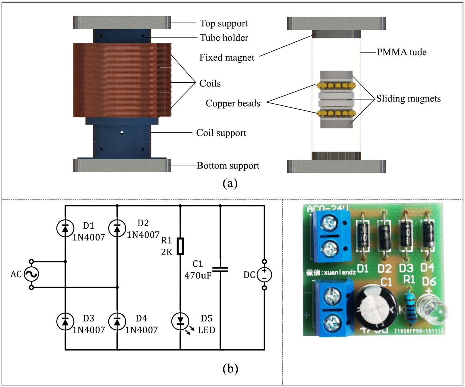
Magnetic-floating energy harvesting system: (a) the MLEH and (b) AC–DC rectifier.
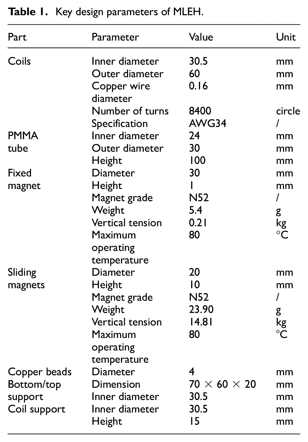
The fixed magnet, sliding magnets and coils are the critical components for capturing vibration energy and converting it into electrical energy. The design parameters of the critical parts of the magnetic levitation energy harvester are shown in Table 1.
Key design parameters of MLEH.
Almost all electronic devices require DC power. Therefore, it is necessary to convert the AC power obtained by the harvester into DC power through an AC—DC power rectifier. In this study, a full-wave bridge rectifier is used, with a maximum output current of 1 A and a maximum input voltage of 30 V. The schematic and hardware of the full-bridge rectifier are shown in Figure 8(b). J1 is the voltage output of the harvester, and J2 is the DC load. When J1 is on the positive half cycle of alternating current, D1 and D3 are turned on, whereas D2 and D4 are cut off due to the application of reverse voltage. In the circuit, J1, J2, D1, and D3 form the energizing circuit, forming a half-wave rectified voltage on the DC load J2.
In the same way, when J1 is on the negative half cycle of the AC voltage, J1, J2, D2, and D4 in the circuit form the energizing circuit, generating another half-wave on DC load J2. Repeatedly, the full-wave rectified voltage is obtained on the DC load J2. Also, D5 is the output DC indicator; R1 is the current limiting resistor; C1 is the filter capacitor.
3.2. Test arrangement
Taking the layout form of sliding magnets, the coil arrangement and the wiring method as control factors, and the output power (mW) as the target factor, a comprehensive FFD test L20 (22 × 5) was conducted, as shown in Table 2. There are two types of sliding magnets (A1, A2), and two types of coil arrangements (B1, B2), and five types of wiring methods. Among them, L1, L2, L3 are the positive pole, and N1, N2, N3 are the negative electrode, as shown in Figure 9.
Test arrangement of L20 (22 × 5).
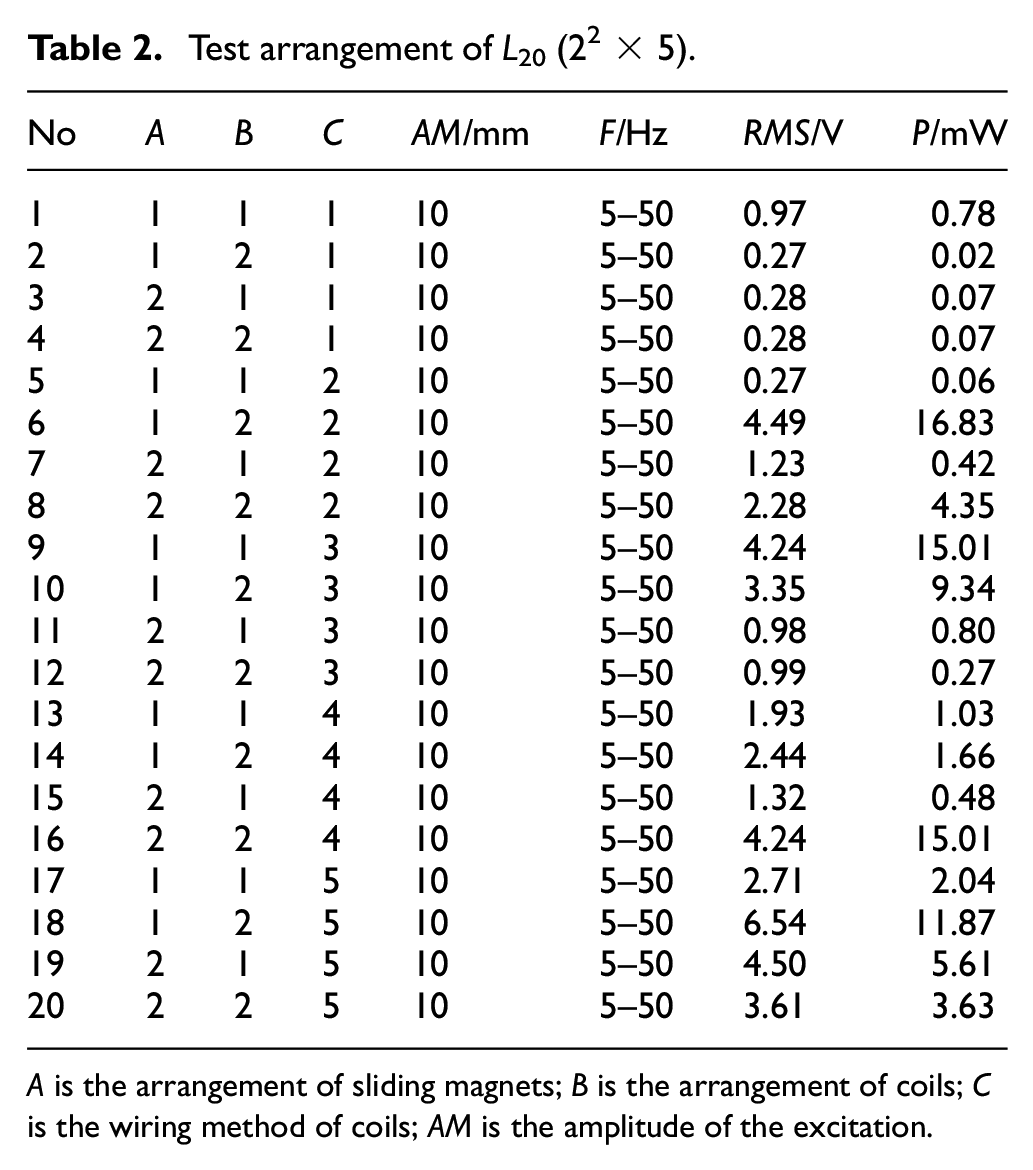
A is the arrangement of sliding magnets; B is the arrangement of coils; C is the wiring method of coils; AM is the amplitude of the excitation.
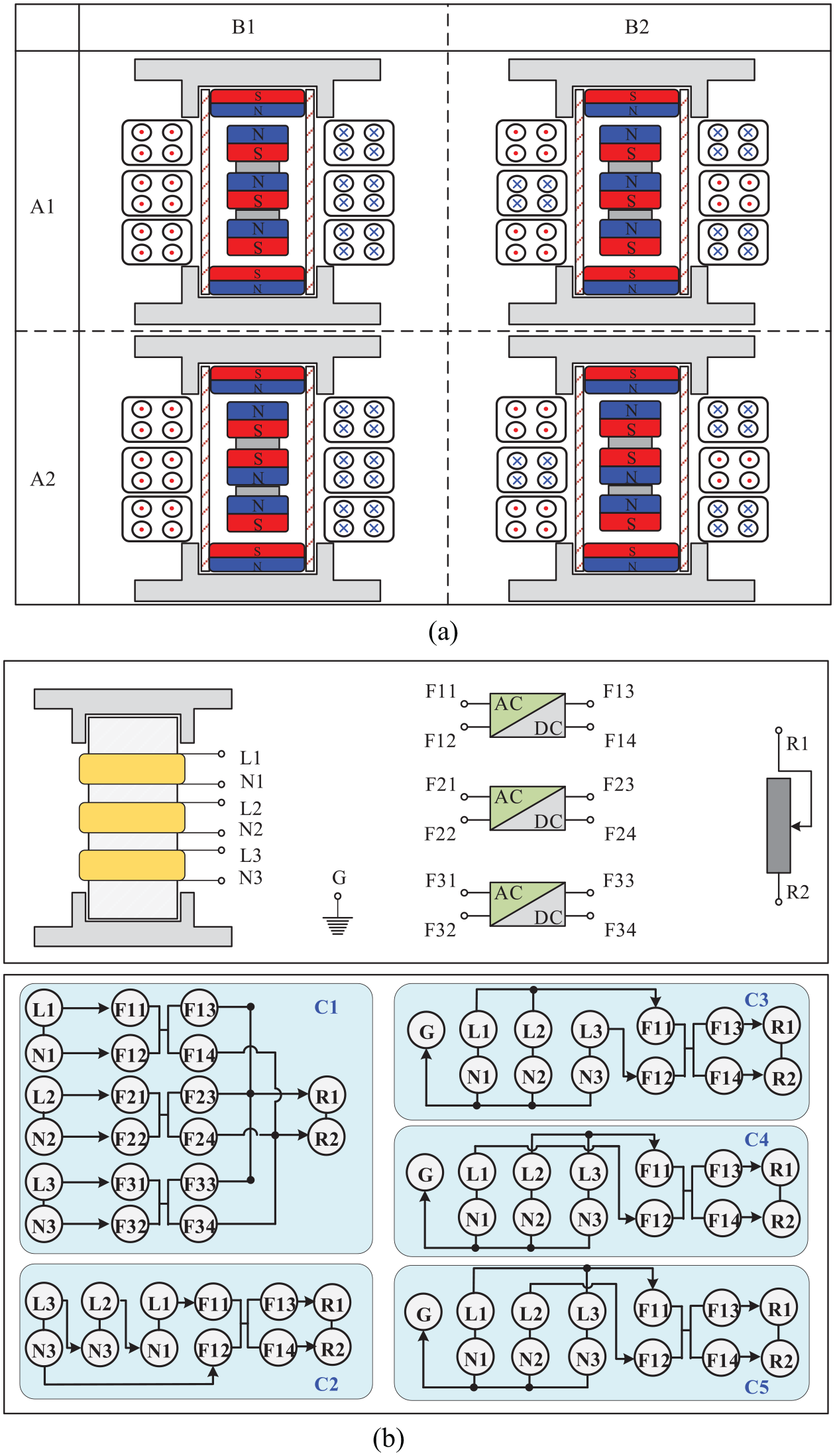
Test arrangement and control factors of MLEH: (a) arrangemnet of coils and sliding magnets and (b) coils connection and wiring approach.
As shown in Figure 9, the two arrangements of sliding triple-magnet are NS-NS-NS and NS-SN-NS, the poles of triple-magnet of the former are mutually attractive, and the poles of magnets of the latter are repulsive. The arrangement of coils mainly changes the winding direction of the middle coil, so that it has an opposite winding direction to that of the upper and lower coils. There are five coil wiring methods: C1 indicates that connecting the AC voltage of the three coils to the rectifier and then to the sliding resistor (load), C2 indicates that the three coils are connected in series as a large coil, and then connected to the rectifier and sliding rheostat. C3 to C5 is similar to the “star connection method” of three-phase AC voltage. The zero wires of the three coils are connected and grounded, whereas two of the three live wires are connected to the rectifier and then to the sliding rheostat.
3.3. Laboratory test
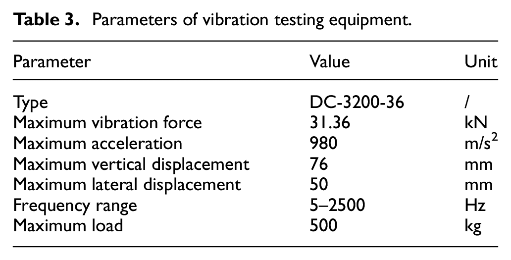
Experimental tests based on sweeping-frequency vibration, fixed-frequency vibration, and random vibration of railroad spectrum are carried out on the shake table (DC-3200-36), the performance parameters of which are shown in Table 3. The MLEH is fixed on the vibration table and suffered vertical excitations. The harvester outputs the DC voltage to the sliding rheostat after the full bridge rectifier. The probe of oscilloscope is connected to the both ends of the sliding rheostat to measure the DC voltage across the sliding rheostat. The specific experimental structure is shown in Figure 10.
Parameters of vibration testing equipment.
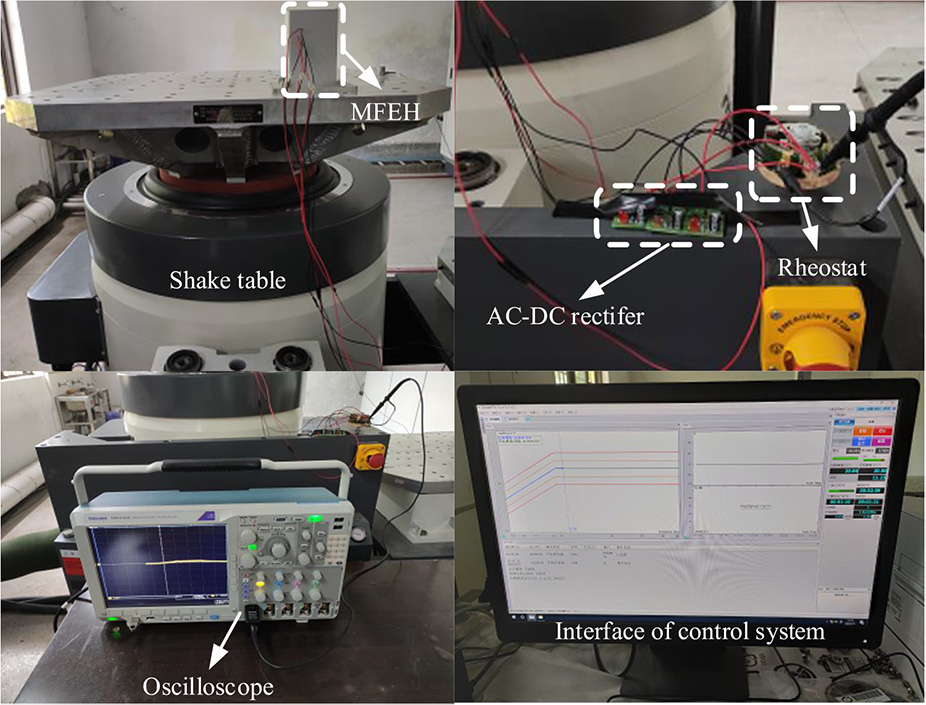
Laboratory test setup.
3.4. Signal processing
Because of the high-frequency emissions from the electromagnetic shaker, the measured voltage signal contains high-frequency noise. Usually, the low-pass filter is adopted to eliminate the disturbance. According to the sampling frequency, scanning ping frequency and the sampling time, a Chebyshev filter is designed and implemented to process the signal.
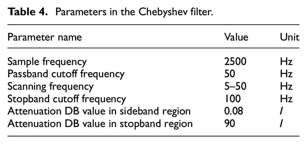
The good filtering effect is achieved by tuning the values of the stopband cutoff frequency, attenuation DB value in the sideband region and attenuation DB value in the stopband region when the program is done. The detailed parameters are shown in Table 4. The collected and filtered signals are shown in Figure 11.
Parameters in the Chebyshev filter.
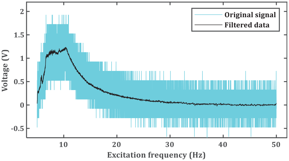
Data processing of the original signals.
3.5. Efficiency and volume figure of merit
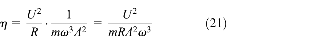
The ratio between the output power, P2, and the input power, P1, of the vibration energy harvester is the efficiency,
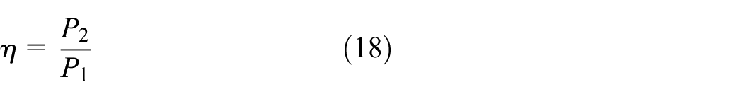
The output power can be calculated according to the following equation,
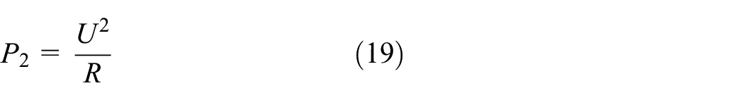
where U is the voltage across the external load, that is, the value after signal processing and filtering, and R the resistance of the external load.
The input power is the power given by the vibrating table obtained by the magnetic levitating vibrator,

where m is the mass of the MLEH,
The efficiency becomes
The maximum output power of the vibration energy harvester of the resonant type of MLEH is
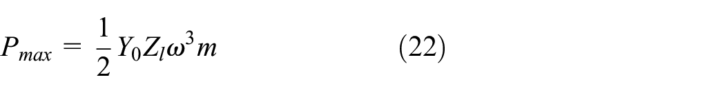
where

For the magnetic levitation-based harvesters, there is no obvious resonance. The maximum displacement Zl of the levitated magnet of this work in the theory maximum power formula is estimated by the maximum distance Zmax of the fixed magnets at both ends (Mitcheson et al., 2004).
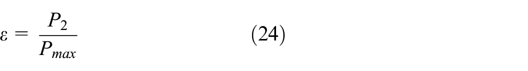
The effectiveness becomes:
The volume figure of merit could be calculated as:
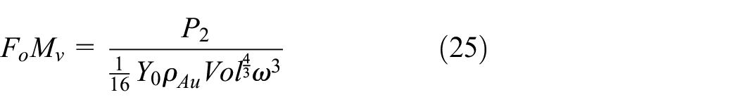
where,
4. Results and discussion
4.1. Influence of control factors on the output voltage and power
The laboratory tests were conducted based on the test arrangements. After filtering the voltage signal collected by the oscilloscope, the output power of MLEH was calculated, as shown in Table 2. To obtain the influences of control factors on MLEH, taking the arrangement form of control factors as abscissa and mean value of output voltage (V) of the corresponding control factor as the ordinate, then the main effect diagram and the interaction diagram is drawn, as shown in Figure 12. As can be seen from Figure 12(a), magnet arrangement, coil arrangement and coil connection all have a noticeable effect on the output power of MLEH. The interaction between magnet arrangement and coil arrangement does not affect the output power of MLEH. In contrast, the interactions among magnet arrangement, coil arrangement, and coil connection influence the output power of MLEH, as shown in Figure 12(b).
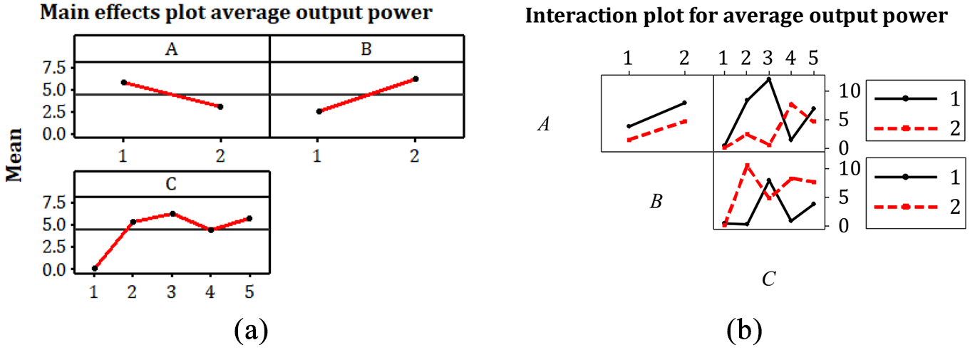
FFD analysis: (a) main effect plot and (b) interaction plot.
According to Table 2, the influence of the arrangement of sliding magnets on the output power of MLEH was studied with other conditions unchanged, as shown in Figure 13. As can be seen from Figure 13, when sliding magnets are arranged in the form of A1 (NS-NS-NS), the output power of MLEH are lower than A2 (NS-SN-NS). Sliding magnets can be seen as a unit magnet when arranged as A1, and part of the magnetic field lines enter the magnet. When sliding magnets are arranged in the form of A2, the three sliding magnets repel each other so that the magnetic force lines inside the magnet can be squeezed out, significantly increasing the density of magnetic induction lines, which are consistent with results in Figures 3 and 4.
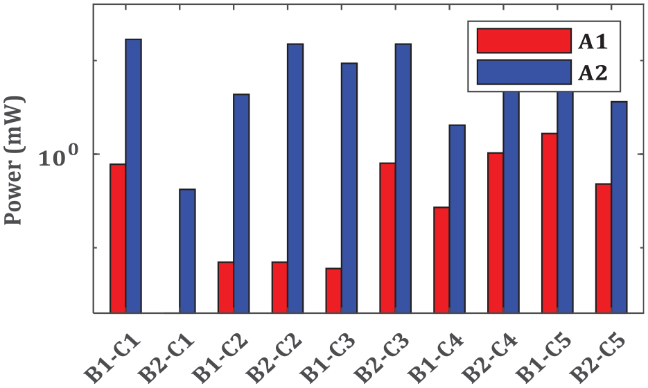
The influence of magnet arrangement on the output performance of MLEH.
Similarly, the influence of coil arrangement on output power is studied with other conditions unchanged, as shown in Figure 14. As can be seen from Figure 14, the output power and voltage of MLEH with coil arrangement B2 are better than B1 in most cases because the AC voltage is directional. When the coils are arranged as B1, the voltages of two adjacent coils may cancel each other out, but the voltage offset by the coil will be greatly reduced when coils are arranged as B2.
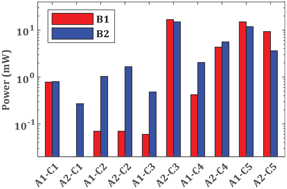
The influence of coil arrangement on the output performance of MLEH.
Figure 15 shows the influence of coil connection on the output voltage and power of MLEH. As can be seen from Figure 15, the output power of MLEH with coil connection of C1 is better than others in most cases. The voltage loss is minimum when the three coils are connected to the AC - DC rectifier and rheostat separately, which avoids the voltage offset when the asynchronous AC voltage is connected in series. The output voltage and power of MLEH with coil connection of C2 are the lowest because the alternating current voltage cancels each other out when three coils form an end-to-end connection and the magnetic induction line is incoherent in the coil at a certain time. It is similar to the “star connection method” when the coil connection is C3, C4, and C5. Since the AC voltage generated by the three coils is not of the same frequency and amplitude and the phase difference with 120°, the output voltage and power of the three connection modes are not the same.
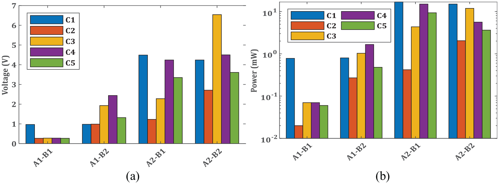
The influence of the connection method on the output performance of MLEH: (a) the influence of connection method on voltage and (b) the influence of connection method on power.
4.2. Frequency-sweeping tests with sinusoidal vibration on the MLEH
According to Table 2, No. 6 is the sample with the highest power of the FFD design group, namely A1B2C2. By using the above filtering method, the output voltage measured by the oscilloscope in 10 cases is shown in Figure 16. The amplitude of the excitation displacement ranges from 1 to 10 mm and all excitation accelerations are the same at 20 m/s2. It can be seen from Figure 16 that the maximum output voltage and power increase with the amplitude of excitation displacement, but the corresponding peak frequencies undergo a decrease. The range of corresponding frequency, output voltage and power are 9.7 to 30.8 Hz, 1.5 to 4.5 V, and 1.80 to 17.0 mW, respectively. Therefore, MLEH has the capacity of generating energy in a broadband.
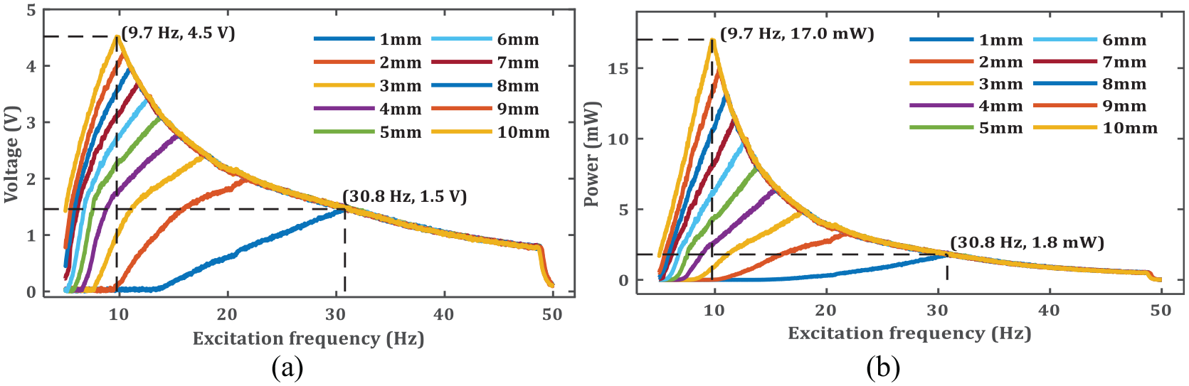
Sweep frequency results: (a) output voltage in different amplitudes during sinusoidal sweeping vibration test and (b) output power in different amplitudes during sinusoidal sweeping vibration test.
4.3. Efficiency and volume figure of merit
The efficiency, effectiveness and figure of merit were studied in this section through the method of section 3.5. The efficiency under three amplitudes and fixed frequency are analyzed and compared with the existing research.
The total weight of the harvester is 1.0 kg, and the input power is calculated at each frequency from 5 to 50 Hz. Table 5 are the listed efficiencies under 1 mm, 5 mm, and 10 mm displacement amplitude at the same acceleration of 20 m/s2, respectively. As we can see from Table 5, there is no significant linear relationship between efficiency and frequency under the same excitation amplitude, and the efficiency generally increases along with excitation frequency. There is no significant relationship between the maximum efficiency and the excitation amplitude, and the maximum efficiency generally decreases with the increase of the excitation amplitude. The maximum efficiency is 1.03‰, 4.91‰, and 2.50‰ under excitations with amplitudes of 1 mm, 5 mm, and 10 mm, respectively.
The efficiency of the MLEH under different amplitudes excitation.
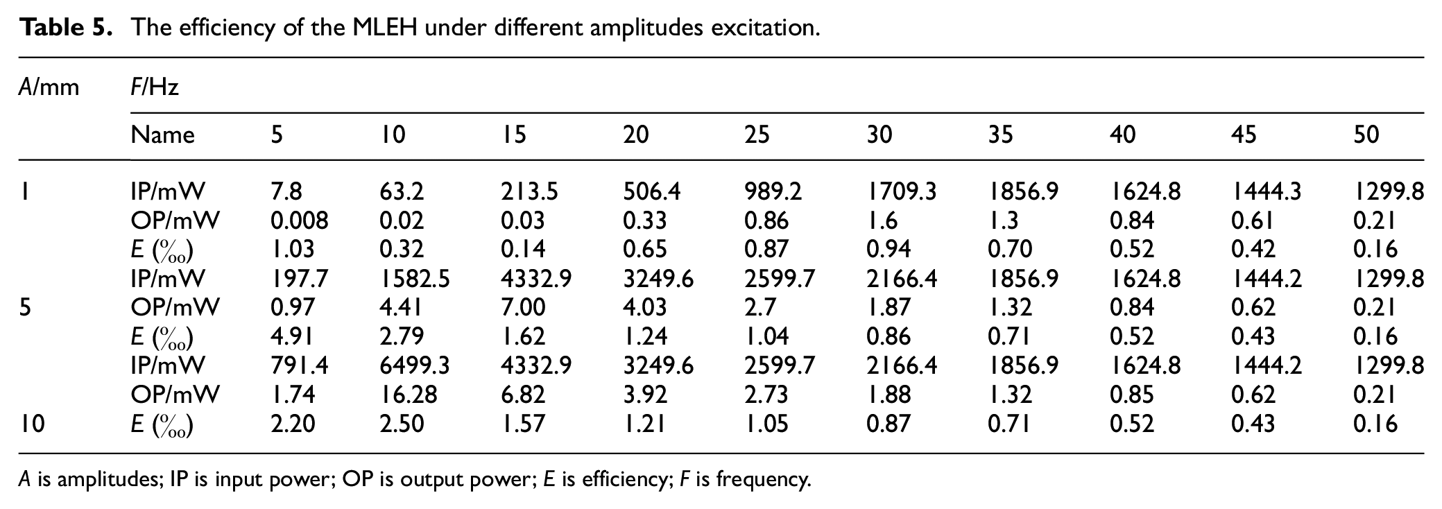
A is amplitudes; IP is input power; OP is output power; E is efficiency; F is frequency.
This proposed MLEH is compared with the state of the art of vibration energy harvester, as listed in Table 6. Researchers have studied diverse types of energy harvester devices at this stage. The appropriate metric for comparison cannot be calculated for lacking necessary information, such as the volume of the entire harvester or the exact operating frequency or the excitation amplitude. Therefore, the efficiency of the objects being compared can be obtained through estimations, which is not very accurate. However, the comparison results can be used as a reference.
Comparison with the state of the art of vibration energy harvester.
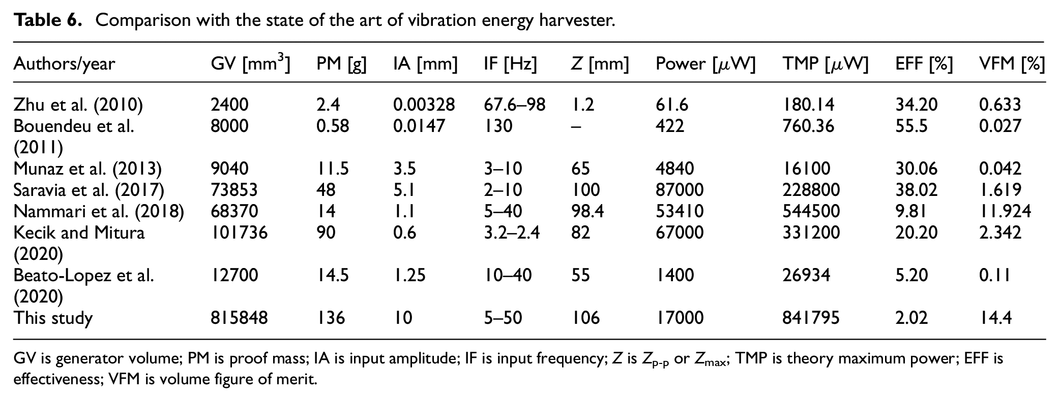
GV is generator volume; PM is proof mass; IA is input amplitude; IF is input frequency; Z is Zp-p or Zmax; TMP is theory maximum power; EFF is effectiveness; VFM is volume figure of merit.
The effectiveness of the proposed MLEH is 2.02%, a relatively small value compared to the maximum effectiveness of 38.02% in reference (Saravia et al., 2017). However, the output power obtained through a closed circuit in this study is more practical than other magnetic levitation-based harvesters using an open circuit.
4.4. Railroad vibration test
The laboratory vibration test loaded with on-site measured random vibration spectrum was realized to represent the actual railway vibration conditions subjected to the traveling loads of the rolling stocks. It can reproduce the vibration signals of railways or trucks that have been collected in advance for a certain period. The vibration acceleration, velocity, and displacement signals of a particular section of high-speed railway in China are shown in Figure 17.
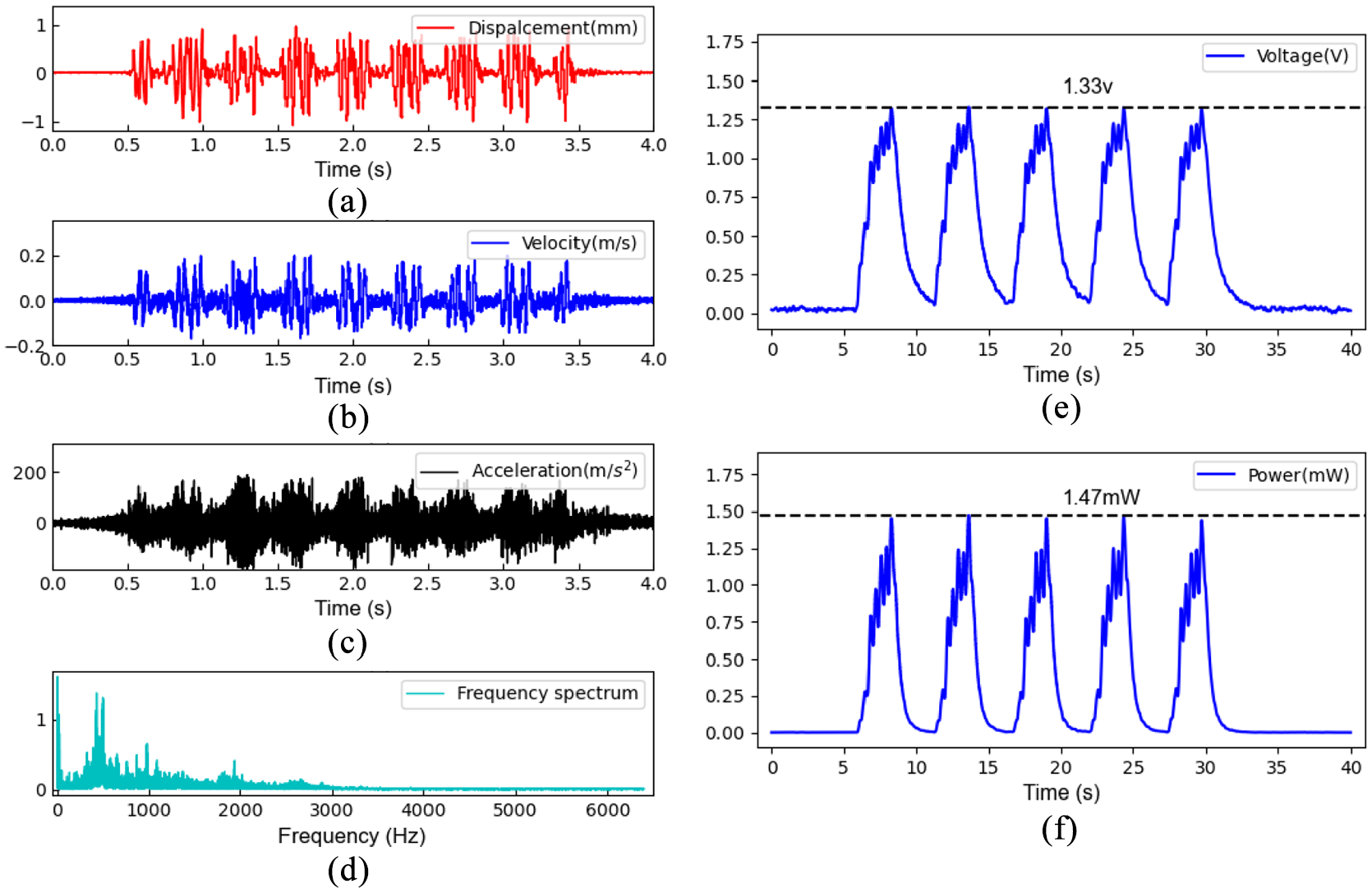
The input vibration excitation of random railroad spectrum and the experimentally measured output: (a) time history of the displacement signals, (b) time history of the velocity signals, (c) time history of the acceleration signals, (d) the frequency spectrum of vibration signals, (e) the measured output voltage and (f) the measured output power of the energy harvester.
As can be seen from Figure 17(a) to (c), the displacement of the rail is relatively small, the maximum displacement amplitude is about 1 mm; the maximum acceleration is about 19g. Figure 17(d) presents the frequency spectrum of vibration signals, indicating that the dominant frequency of rail vibration is below 3000 Hz. The filtered data of the induced voltage and power are shown in Figure 17(e) and (f). It can be seen that the maximum voltage obtained by MLEH is 1.33 V, and the maximum power is 1.47 mW. The output voltage of more than 1 V indicates that the vibration energy harvester in this study can charge commonly used energy storage devices such as batteries via the DC-DC module developed in our previous study under the actual excitation conditions of extremely small rail displacement, and then drive the wireless sensor to work.
5. Conclusion
In this study, a vibration harvester using magnetic levitation was designed, and the influence of coil layout, magnetic polarity arrangement and wiring method on deliverable output power was studied. A preferred combination with the maximal output power was selected. The selected vibration energy harvester was tested by frequency-sweeping tests and measured railroad vibration data, and the broadband frequency and load characteristics of the designed device were verified. The paper draws the following conclusion:
The interaction effects of coil layout, magnetic pole arrangement and wiring method have a significant influence on the performance of the MLEH. The opposite winding directions of the three coils are better than the same direction winding, and the repulsive type arrangement of sliding magnets is better than the mutually attractive type. The three coils are connected to the rectifier and then to the load to obtain the output power. This is consistent with theoretical analysis, that is, the alternating voltage has directivity and the arrangement of the repulsive magnet can squeeze out the internal magnetic lines, greatly enhancing the magnetic induction line density across the coils.
For the frequency-sweeping tests of the prototype, the maximum output voltage increases with the excitation amplitude. However, its corresponding cross-over frequency decreases. The range of cross-over frequency, maximum output voltage, and maximum output power are from 9.7 to 30.8 Hz; 1.5 to 4.5 V, and 1.80 to 17.0 mW. Thus, the proposed MLEH has a broadband power generation capacity.
Maximum voltage and power of MLEH are 1.33 V and 1.47 mW under the measured railroad spectrum. The output voltage of more than 1 V shows that the MLEH in this study can be used to charge standard energy storage devices such as batteries and drive rail-side sensors through a dc-dc booster. It demonstrates the power generation capacity under a random railroad spectrum and indicates the practicability of the proposed MLEH.
The maximum efficiency of the presented MLEH is 1.03‰; 4.91‰, and 2.50‰ at 1 mm, 5 mm, and 10 mm amplitude excitations, respectively. The effectiveness of the proposed MLEH is 2.02%. The volume figure of merit is good compared to other magnetic levitation-based harvesters, indicating a high power density and promising application for powering the rail-side sensors.
Footnotes
Declaration of conflicting interests
The author(s) declared no potential conflicts of interest with respect to the research, authorship, and/or publication of this article.
Funding
The author(s) disclosed receipt of the following financial support for the research, authorship, and/or publication of this article: This work was supported by the National Natural Science Foundation of China (Grant No. 52008343); Chongqing Science and Technology Bureau (Contract No. cstc2019jscx-gksbX0148)’ Chongqing Municipal Education Commission (Grant No. KJCX2020006).