
Abstract
An analytical model is presented for the generation, sensing, and time-reversible process of Lamb waves in thin isotropic plates with surface-bonded piezoelectric wafer transducers, incorporating the shear-lag effect of the bonding layer and inertia effects of the system in transducer modeling. A one-dimensional dynamic shear-lag model for the actuator-plate interaction is used to obtain the shear stress distribution at the actuator-plate interface. The Lamb wave solution for the plate under this shear traction excitation is obtained using the two-dimensional (2D) elasticity equations. A consistent sensor-plate interaction model incorporating the shear-lag and inertia effects is developed to determine the induced sensor voltage from the Lamb strain at the plate surface. The model is validated by comparing it with the 2D coupled piezoelasticity-based finite element simulation and experimental data. Detailed parametric studies are conducted to illustrate the effect of inclusion of inertia of actuator, sensor, adhesive, and plate in the transducer modeling on the Lamb wave generation, sensing, time reversibility, and the system’s best reconstruction frequency, and to ascertain how various geometrical and material parameters of the system influence the same. The developed closed-form solution will be immensely useful for the design of Lamb wave based structural health monitoring systems.
Keywords
Introduction
Lamb wave based techniques have attracted increasing interest in the last two decades for structural health monitoring (SHM) of thin plate/shell-type structures encountered in aircraft (Dalton et al., 2001), space vehicles (Giurgiutiu et al., 2011; Huang, 2001), pipelines (Huan et al., 2020), pressure vessels (Hu et al., 2020), wind turbine blades (Druffner et al., 2011) etc. The advantages of using ultrasonic Lamb waves for damage detection in such thin-walled structures are its ability to travel long distances at high speed, ease of activation and sensing, ability to detect both surface and internal damages of small size, and low energy consumption. Piezoelectric patches/wafers and piezoelectric fibre reinforced composites (MFCs) have emerged as the most preferred transducers for actuating and sensing Lamb waves because they are very thin, non-intrusive, minimally invasive, and inexpensive, and can be conveniently surface-mounted on existing structures or embedded in laminated structures using adhesives (Collet et al., 2011; Giurgiutiu, 2003). An analytical model which can accurately capture the dynamic interaction between the piezoelectric actuator/sensor and the host structure, and provide an accurate solution for actuation, propagation and sensing of Lamb waves, is in fact essential for the effective and optimal design of such guided wave based SHM systems.
The initial studies on the analytical solutions of Lamb wave actuation, propagation, and sensing assumed the strain transfer from the actuator to the plate to take place at the edges of the actuator. It is known as the pin-force model, which is essentially the result of two premises: (i) the actuator has a negligible thickness and (ii) the bonding between the actuator and the plate is perfect. Both these premises, however, do not represent the real situation, because of which the actual shear transfer is spread over an area near the edge (Kapuria and Kumari, 2013). This interfacial stress distribution, of course, has a large influence on Lamb wave generation and sensing (Shevtsova et al., 2019).
Lin and Yuan (2001) presented an analytical solution for propagation of fundamental antisymmetric mode (
The important role that the adhesive layer between the piezoelectric transducer and the host structure plays has been experimentally established for the electromechanical impedance and resonance frequency of the transducers (Islam and Huang, 2014; Qing et al., 2006), actuation and sensing of Lamb waves (Ha and Chang, 2010; Islam and Huang, 2016; Pohl et al., 2012; Sirohi and Chopra, 2000) as well as its time reversibility (Agrahari and Kapuria, 2016a). The first actuator-to-structure stress transfer model which incorporated the effect of the adhesive layer was presented by Crawley and Luis (1987) for a beam-type host structure with two collocated piezoelectric actuator patches bonded on both surfaces of the beam. The model, known as the shear-lag model, was developed for quasi-static actuation, considering Euler-Bernoulli theory for the beam and membrane-type behaviour of the thin transducer. Giurgiutiu (2005) modified the model for the case where a single actuator is bonded to one side of the beam, which in general generates both symmetric and anti-symmetric modes of guided waves simultaneously. Lanza di Scalea and Salamone (2008) used this quasi-static shear-lag model for stress transfer between the transducer and the host plate to improve the previous pin-force model based solution (Giurgiutiu, 2005) for actuation and sensing of Lamb waves in a thin isotropic plate with surface-bonded piezoelectric transducers under an harmonic excitation. However, the solution for the sensor potential suffers from inconsistencies and does not satisfy the appropriate boundary conditions.
The shear-lag model for the transducer-plate interaction used in the aforementioned studies is based on a plane stress assumption, while the wave propagation solution corresponds to the plane strain condition of the plate. A recent study based on a 2D shear-lag solution for the interfacial shear stresses for a rectangular transducer (Kapuria and Agrahari, 2016) has, however, shown that for a square-shaped piezoelectric transducer, the shear stress distribution at the transducer-plate interface matches with the stress distribution obtained from the 1D shear-lag model developed considering the plane strain assumption for the transducer and the plate. Based on this observation, Kapuria and Agrahari (2018) presented a closed-form time domain analytical solution for actuation and sensing of Lamb waves in plates with surface-bonded actuators and sensors using the plane strain 1D shear-lag model for the transducers. In this formulation, a consistent model for the sensor was developed satisfying the appropriate boundary conditions. In another development, Shan et al. (2017) presented a theoretical framework for the Lamb wave generation, propagation and sensing considering the adhesive nonlinearity. The model, however, did not provide a closed-solution for the sensor output, and it too employed the plane stress 1D shear-lag model for the transducer.
Although in Lamb wave based SHM applications, the piezoelectric transducers are excited dynamically, all the earlier studies employed quasi-static solutions for transducer-structure interaction for actuation and sensing, neglecting the inertia of the transducer and structure. However, the inertia effect of the transducers can not be neglected for high frequency excitations, when the wavelength is comparable to the length of the transducer (Wang and Huang, 2006). Studies have shown that the Lamb wave response obtained using the quasi-static shear-lag solution differs significantly from detailed elasticity based FE solutions at the high frequencies generally used for SHM (Kapuria and Agrahari, 2018). Therefore, it is necessary to develop an analytical solution for Lamb wave generation and sensing, considering the inertia effect in the actuator and sensor models.
An analytical actuator model for the dynamic stress transfer between a piezoelectric actuator and an isotropic host plate subjected to guided waves was developed by Huang et al. (2010) considering the actuator inertia. The model directly coupled the 1D equation of inplane motion of the thin actuator with the 2D elasticity based wave equation for the plate in terms of the interfacial shear stress. An approximate numerical solution of the coupled integral equations was obtained using the method of collocation. The study did not include the important effect of the bonding layer. Han et al. (2008) presented a similar solution in the integral form for dynamic response of a sensor bonded to an elastic half-space, which modelled the bonding layer. Like the actuator model, this sensor model too did not offer a closed-form solution.
Dugnani (2016) attempted a modification to the classical quasi-static shear-lag model of Crawley and Luis (1987), introducing the transducer inertia. However, to maintain a similar solution like the original study, the interfacial shear stress was expressed as a single term solution (considering symmetry), irrespective of the fact that the governing deferential equation was of the fourth order. Furthermore, he neglected the inertia term of the host structure, which too has a notable effect on the sensor response. Recently, Kapuria et al. (2019) proposed a consistent extension of the quasi-static shear-lag model by considering the inertia of the transducer, the host plate as well as the bond layer, which yielded a closed-form solution for the dynamic stress transfer between the harmonically excited piezoelectric actuator and the isotropic host plate. The model has been developed considering the plane strain condition for both the actuator and the host plate, following the inferences made in Kapuria and Agrahari (2016). A comparison with the detailed 2D FE solutions showed that the dynamic shear-lag model predicts dynamic interfacial shear stress distribution accurately at high excitation frequencies. Such a dynamic shear-lag model is at present not available for sensors. Likewise, to the best of authors’ knowledge, no closed-form analytical solution incorporating the dynamic effects of the constituent elements in the transducer models has been reported so far for generation and sensing of Lamb waves in thin isotropic plates with surface-bonded piezoelectric transducers.
The time reversal process (TRP) of Lamb waves (Fink, 1992) has gained immense popularity as a baseline-free damage detection technique for thin-walled structures (Kannusamy et al., 2020; Park et al., 2007; Poddar et al., 2011). In the TRP, the input response can be reconstructed at the actuator location after emitting back the time reversed version of the forward response obtained at the sensor location, in the absence of damage. The damage can thus be identified by comparing the reconstructed signal with the original input signal. An accurate analytical solution for the TRP of Lamb wave is very important for the design of SHM systems based on the TRP and also to arrive at theoretical estimation of the frequency of best reconstruction at which the time reversal method would be most effective (Agrahari and Kapuria, 2016a, 2016b). No such model including inertia effect in the transducer models is available at present.
In this paper, we present a closed-form analytical solution for generation and sensing of Lamb waves in an isotropic plate with an actuator and sensor, adhesively bonded to its surface, incorporating shear-lag and inertia effects in transducer modeling. We study the problem of Lamb wave propagation in the plate in two dimensions under the plane strain condition, considering plane waves. However, a two dimensional (2D) solution for the transducer-bond layer-plate system for actuation and sensing of Lamb waves would be very complex. A simple but effective way of overcoming this complexity is to model the transducers and the plate using the 1D panel theories so as to ascertain the shear stress induced on the plate by the actuator and the sensory potential induced in the sensor by the strain developed in the plate due to Lamb waves. Such 1D models for the actuator and sensor were employed earlier without considering the inertia of the transducer, plate and the adhesive (Kapuria and Agrahari, 2018), which plays an important role on the accurate prediction of the actuated shear stress and sensor potential. Besides, the previous sensor models did not satisfy the stress-free condition at both edges of the sensor. In the present formulation, the shear stress induced at the actuator-plate interface is obtained using the dynamic shear-lag model developed previously by the authors (Kapuria et al., 2019) considering the inertia effect. The solution for the Lamb wave displacement field is obtained for this shear excitation in the frequency domain. Next, a consistent sensor-plate interaction model is developed for the first time considering shear-lag and system inertia effects, and satisfying the appropriate boundary conditions at the sensor.
The sensor model transforms the displacement field on the plate surface at the sensor location into the induced sensor potential. The reconstructed signal after the TRP is computed in the frequency domain by making use of the transfer function obtained from the forward sensor response. Finally, the time domain responses for both forward propagation and the TRP are obtained using the inverse Fourier transform. The model is validated by comparing the results with piezoelasticity based FE solutions. A detailed parametric study is performed to understand the effects of inertia of the actuator, sensor, adhesive, and plate in the transducer modeling on the Lamb wave actuation, sensing, time reversibility, and the system’s best reconstruction frequency.
Actuator-plate interaction model considering inertia
Consider an isotropic plate of thickness
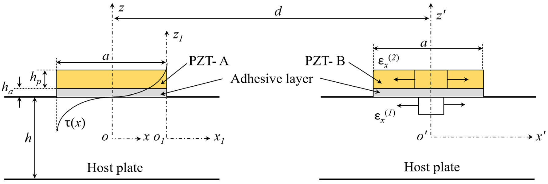
Transducer-adhesive-plate system in pitch-catch mode.
The piezoelectric material is considered to be of class mm2 symmetry with the poling direction along the
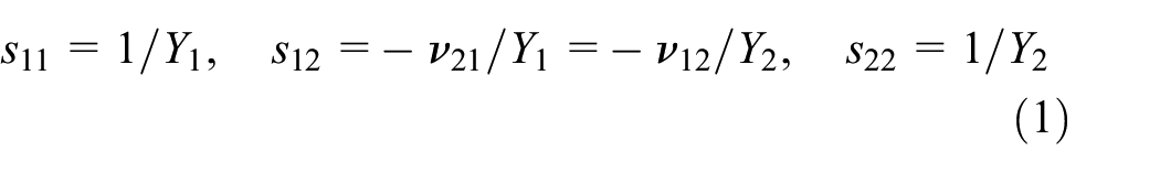
The Young’s modulus and Poisson’s ratio of the isotropic plate are
Consider that PZT-A (Figure 1) is actuated with an electric potential signal

where
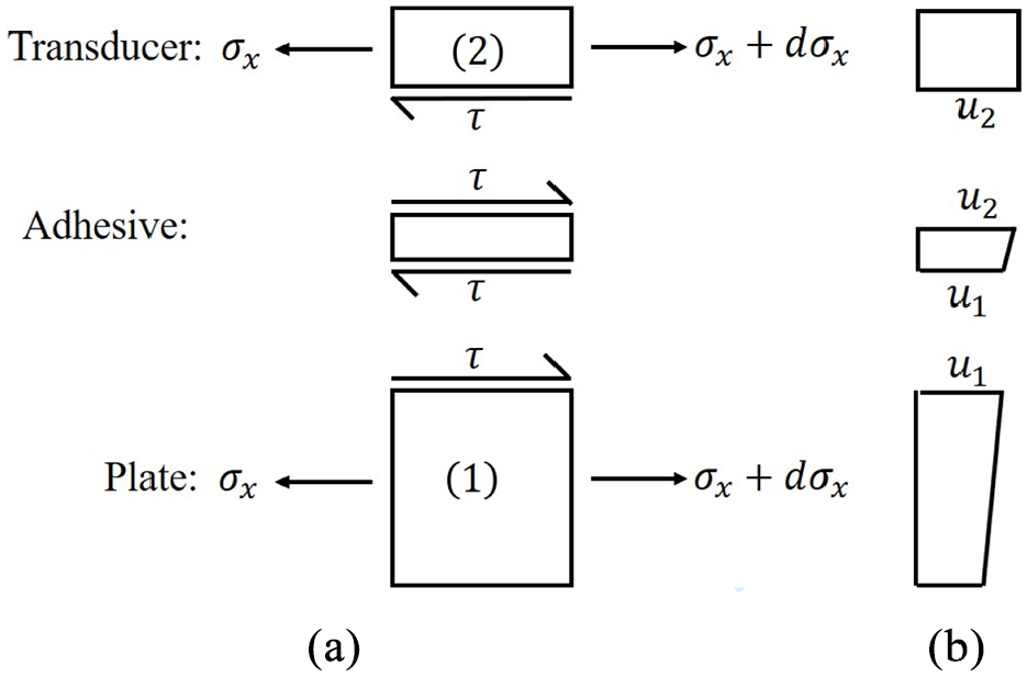
Stress transfer between transducer and host plate, and variations of inplane displacement across different elements: (a) free body diagrams and (b) variations of inplane displacement u.
In the 1D model, the displacement field in the plate is assumed to follow the classical Kirchhoff theory approximations, while the piezoelectric transducer is assumed to undergo a membrane deformation with a uniform inplane displacement across the thickness. Let
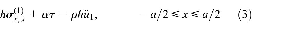
where a subscript comma followed by
As the inplane stiffness of the adhesive layer is neglected, its inertia in the longitudinal direction is assumed to be resisted by the piezoelectric transducer and hence added to the inertia term in the equation of motion of the transducer. Assuming a linear variation of the inplane displacement
The shear stress-strain and strain-displacement relations for the bonding layer under pure shear yields

where
Using equation (5), the constitutive equation (2) and the strain-displacement relations, equations (3) and (4) can be expressed as
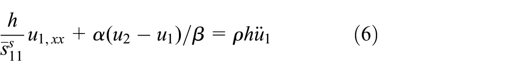

The subscript/superscript
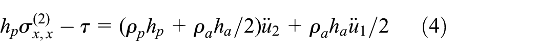
For a harmonic excitation

where

where
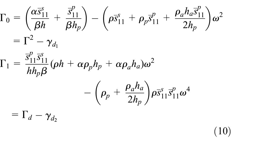
where
and

where
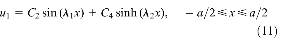
In the region beyond the actuator patch (

where
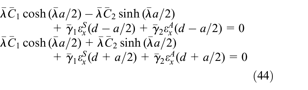
The stress-free boundary condition at the free edges of the actuator yields

The inplane displacement and stress in the host plate need to be continuous at the interface between the transducer region and free region of the plate at
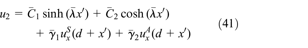
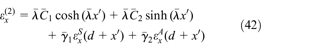
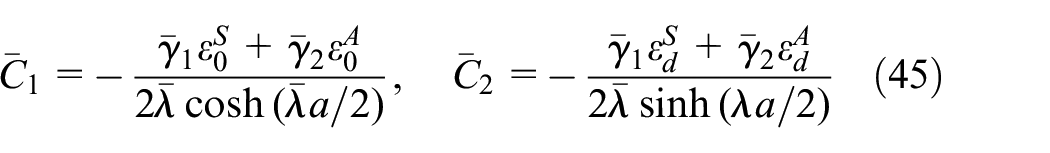
The three unknown constants
Finally, substituting the resulting expressions for
where
and
Elasticity solution for Lamb wave propagation
The wave equations for an isotropic plate (Figure 1) under plane strain condition can be expressed in terms of displacement potentials as
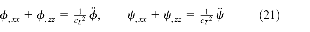
where
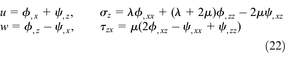
The boundary conditions at the top and the bottom surfaces of the plate are

For the harmonic electric potential and consequently harmonic interfacial shear excitation

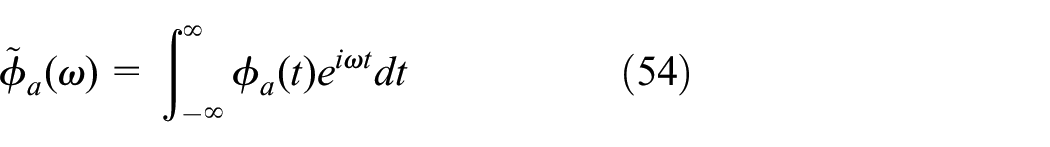
We employ the Fourier transform in
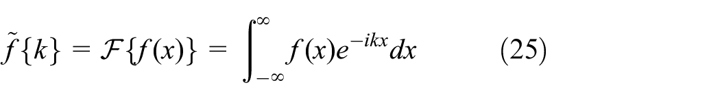
and the inverse transform is defined by
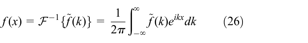
where

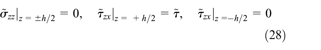
where
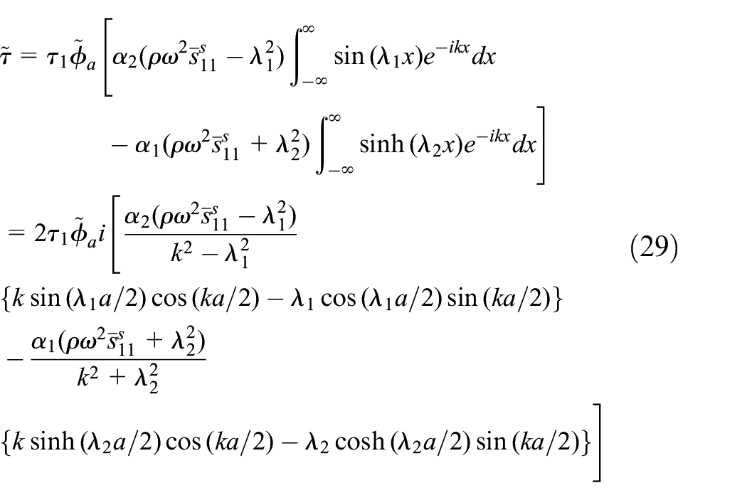
Equation (27) has trigonometric functions as its solution whose arbitrary constants are determined from the boundary conditions given by equation (28). Applying inverse Fourier transform to the resulting solution in the wavenumber domain and using the residue theorem, the inplane displacement
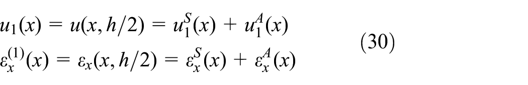
with
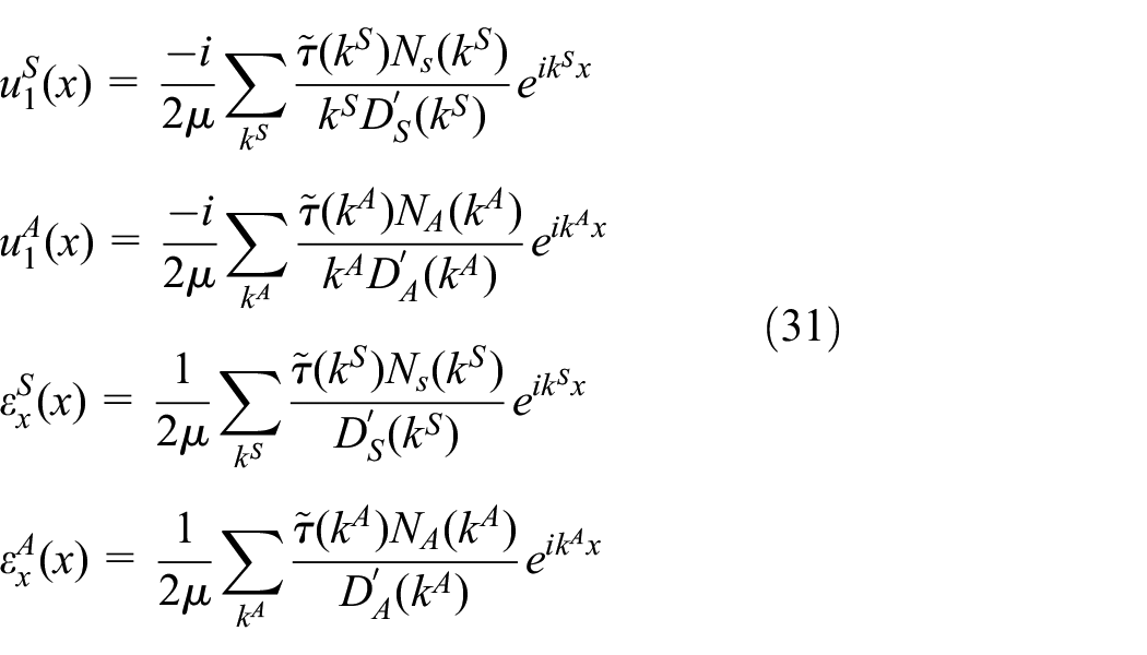
and
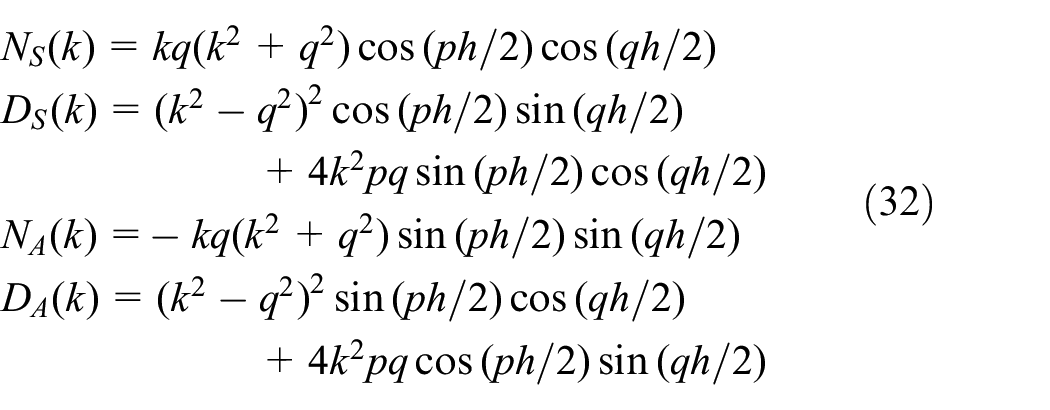
where
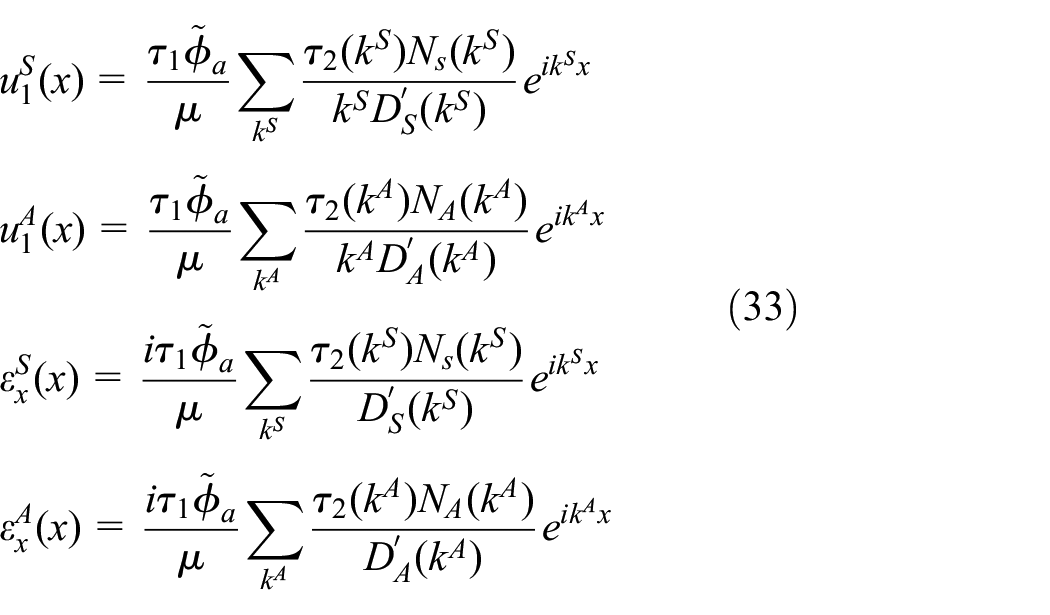
where
Sensor-plate interaction model considering inertia
Having obtained the solution for the Lamb wave at the top surface of the plate, we need to determine the electric potential induced in the sensor. The governing equation of motion developed in equation (7) for the actuator holds good for the sensor (PZT-B of Figure 1) as well:
Substitution of equations (8) into (35) yields

where
Considering that

where

where
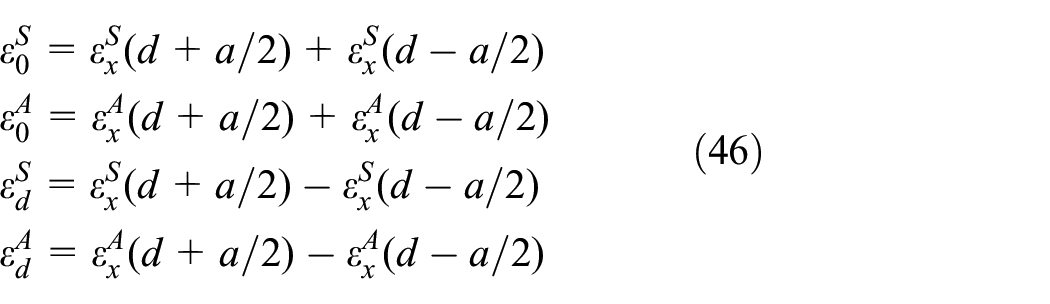
Thus, the complete solutions of the inplane displacement and strain of the sensor become
where
The stress-free boundary conditions at the free edge of the sensor yields

Substitution of equations (42) into (43) yields
which are solved for constants
where
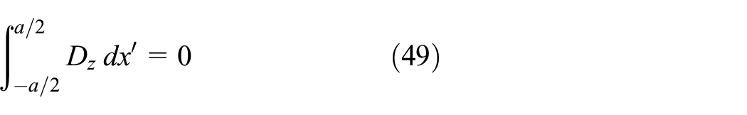
The transverse electric displacement

where

where
On substitution of equations (48) into (49) yields the potential
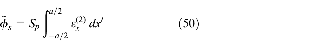

where
Note that when the inertia is neglected in the sensor model,
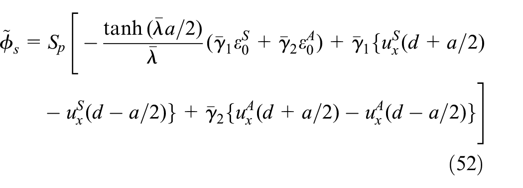
Equation (52) can be expressed in the form

where
Having obtained
Time-reversal response of Lamb wave
In the time-reversal process, the forward response is reversed in time and then reemitted at the sensor (PZT-B). The time reversal operation in the time domain is equivalent to taking complex conjugate of the signal in the frequency domain. Thus, using equation (53), the time reversed version of the forward response in frequency domain is obtained as

where a superscript * denotes complex conjugate of a variable. The reconstructed response at the actuation point is obtained again by using equation (53) as

which, on substitution of equation (56), yields

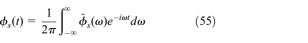
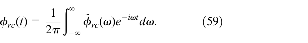
Finally, the reconstructed signal in the time domain is obtained by applying the inverse Fourier transform to
Time reversibility
The time reversibility of the system at a particular excitation frequency is obtained by comparing the main wave mode of the reconstructed response with the original input signal after normalizing with respect to corresponding peak amplitude. The time reversibility is quantified by percent similarity between the reconstructed and the input signal based on
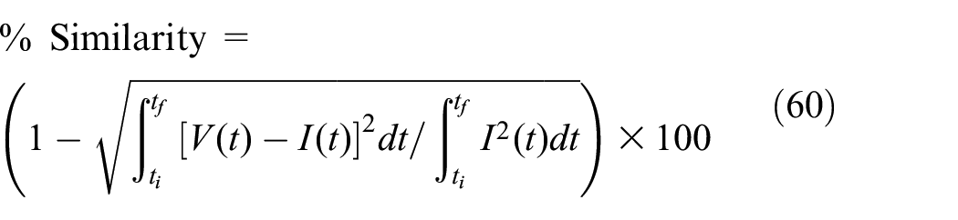
where

where
Results and discussion
Validation
To validate the proposed analytical model, a detailed FE simulation is performed for Lamb wave actuation, propagation, and sensing using the commercially available FE software ABAQUS 6.14 standard. Figure 3 shows the transducer-adhesive-plate system considered for this purpose, with
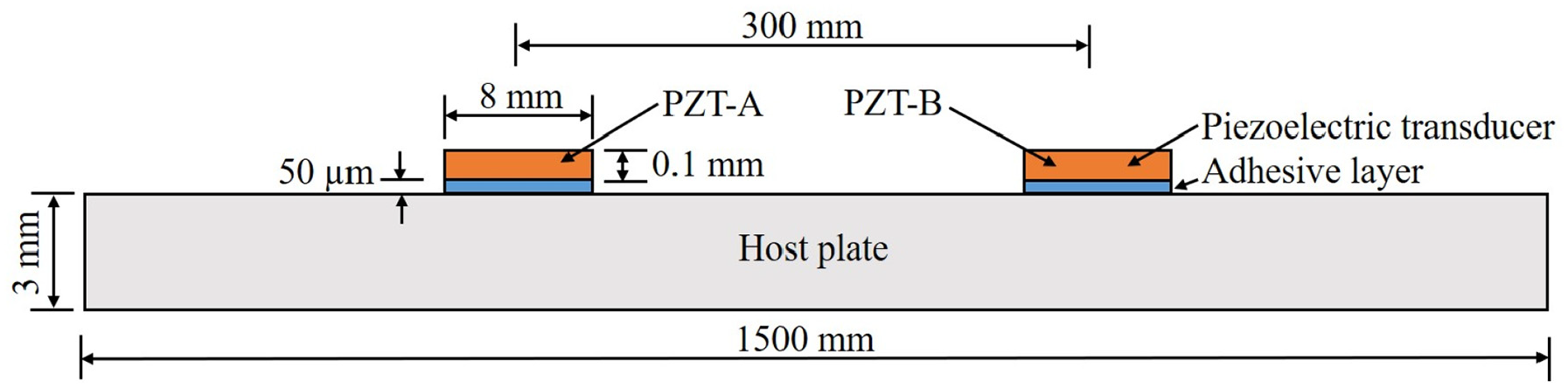
Transducer-adhesive-plate system considered for analysis.
Material properties.
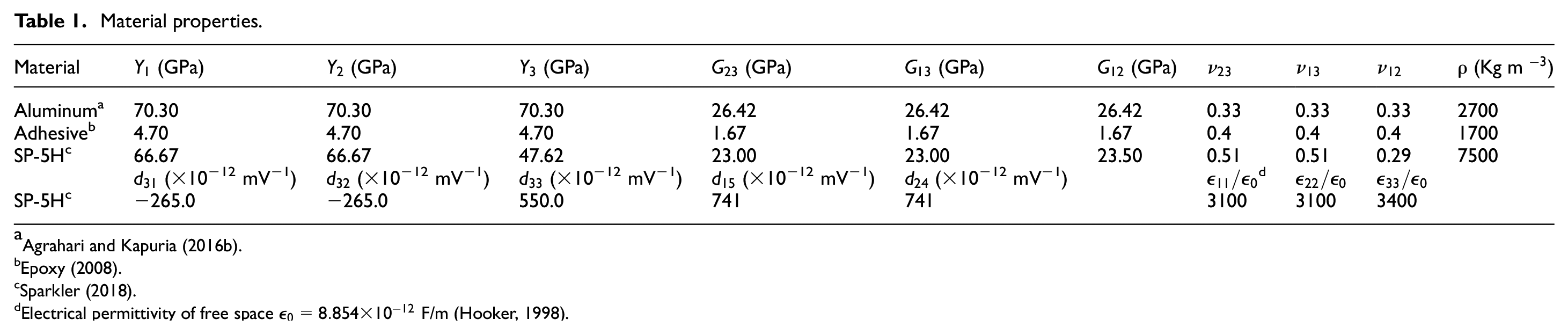
Electrical permittivity of free space
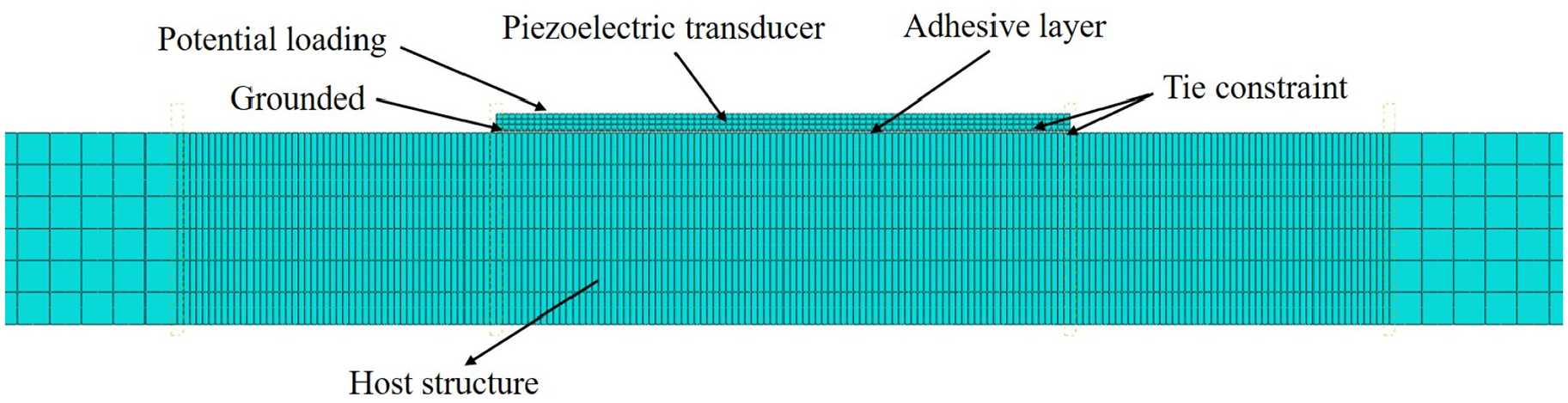
Mesh configuration shown for a portion of actuator patch in the 2D FE model.
For the forward response, PZT-A (Figure 3) is actuated with a Hann window modulated five cycle tone burst signal of 20 V amplitude. The input signal is given by
First, to validate the proposed model in respect of Lamb wave generation and propagation, the inplane strain
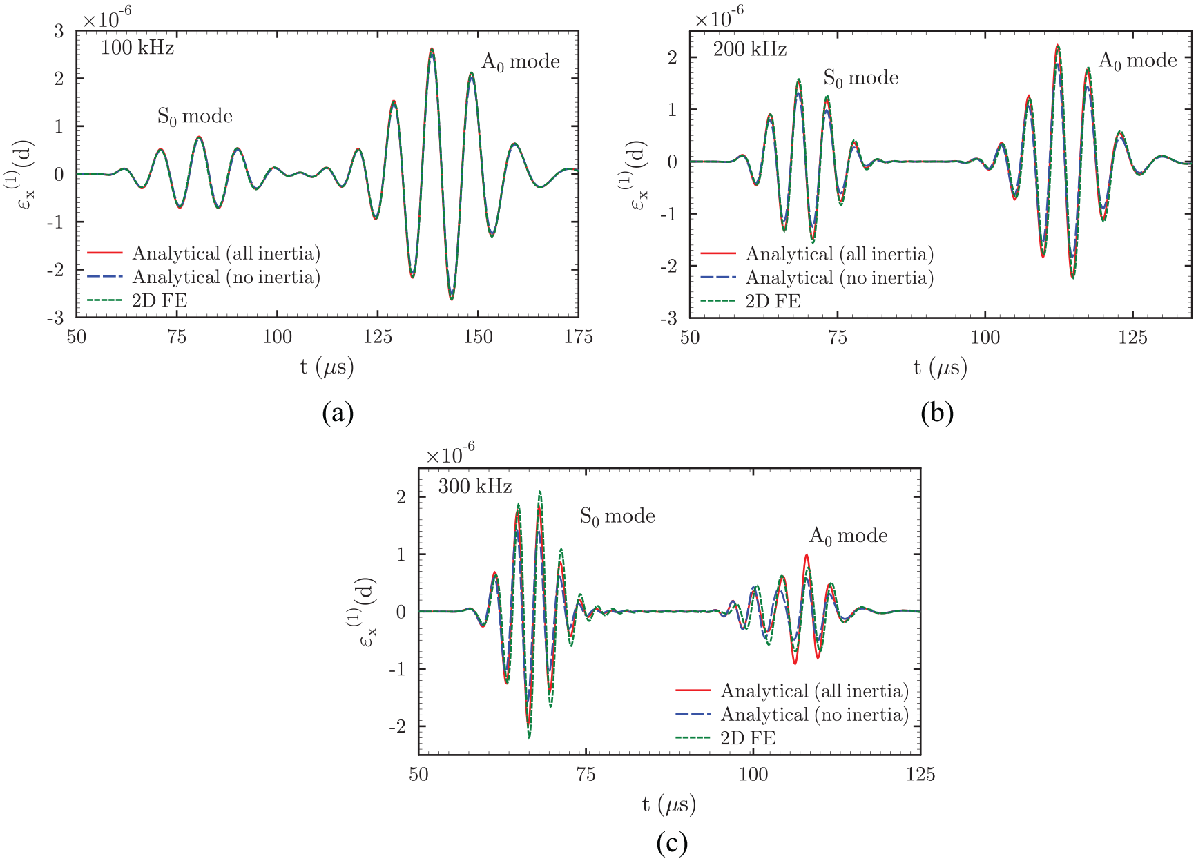
Longitudinal strain
The sensor potential
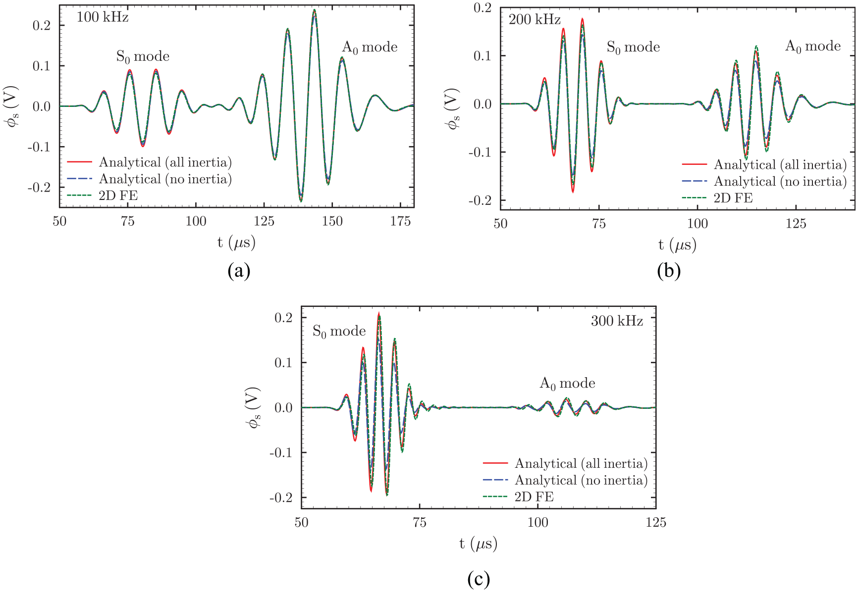
Sensor potential
For further validation, the present solution is also compared with the experimental results presented by Sharma et al. (2020) for a similar system as in Figure 3 with the same plate and adhesive layer thickness but with transducers of 0.25 mm thickness. The transducer size used in the experiment is 10 mm, but a reduced size of 9 mm is considered for the 2D FE simulation and the analytical solution to compensate for the possible weak bonding around the edges of the transducer in the experimental set-up (Sharma et al., 2020). A recent study (Agrahari and Kapuria, 2016a) has shown that although a full-field 3D FE solution differs from the simplified plane strain 2D FE solution in terms of actual magnitude of the voltage response, the two solutions match well when they are normalized with respect to their respective peaks. Therefore, we compare the present analytical and 2D FE solutions with the experimental data after normalization. Figure 7 depicts this comparison for an excitation frequency of 200 kHz, which shows good agreement between the three results.
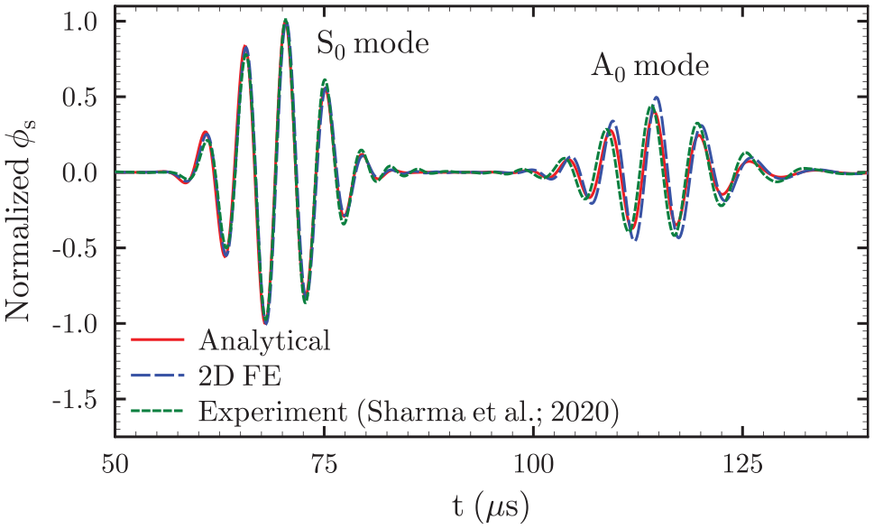
Comparison of present solution with 2D FE solution and experimental data for a 200 kHz modulated five-cycle tone burst excitation in a 3 mm thick plate.
Effect of inertia terms on Lamb wave response
A detailed study is conducted in this section using the developed analytical model to illustrate the effect of the inertia terms in transducer modeling on the Lamb wave strain and sensor response as well as the influence of various geometrical and material parameters on the same. For this purpose, we consider a system with
Effect of inertia of individual components
To understand the effect of inertia of the individual components of the system, that is, the plate, adhesive layer, and the piezoelectric transducers on the Lamb wave and the sensor response, the solution is obtained for four different cases: (i) considering inertia of all constituents (All inertia), (ii) neglecting the transducer inertia (
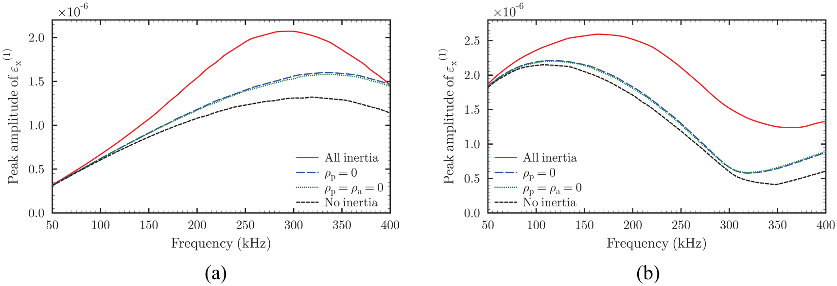
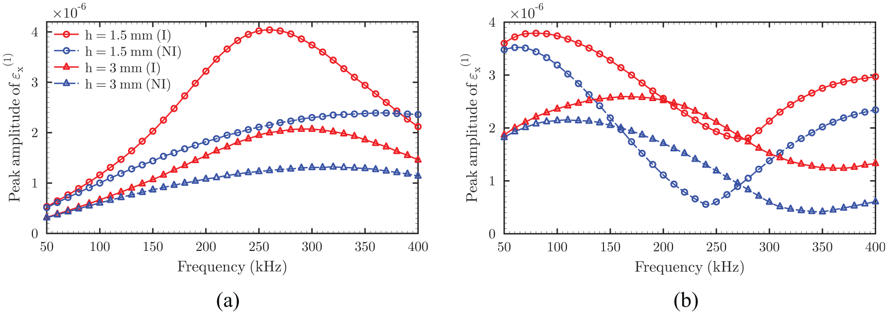
Effect of inertia on the peak amplitude of the strain
The peak amplitudes of the waveforms in the response signal are obtained from its Hilbert envelope (Sharma et al., 2020). For both
When the inertia effect is neglected in the actuator-plate interaction model, the peak of
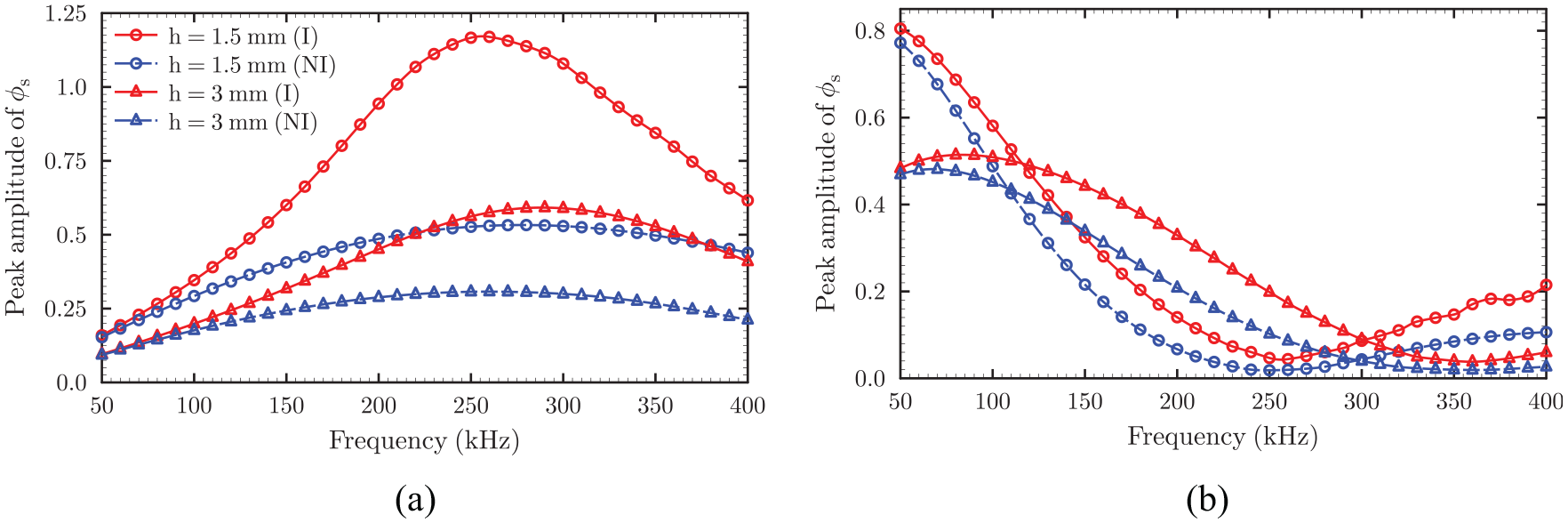
Figure 9 depicts similar variations of the peak amplitude of the sensor potential response with the excitation frequency for
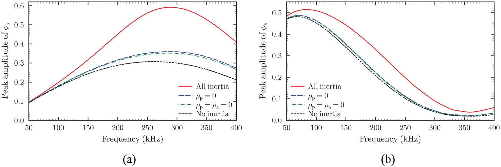
Effect of inertia on the peak amplitude of sensor potential for: (a)
Influence of adhesive layer thickness on inertia effect
To understand how the thickness of the bonding layer influences the inertia effect, the peak amplitude of the Lamb strain for three values of adhesive thickness is plotted against the excitation frequency in Figure 10, for both
Effect of adhesive thickness on inertia effect on the strain at top surface of the host plate at sensor location (
Effect of adhesive thickness on inertia effect on the sensor potential: (a)
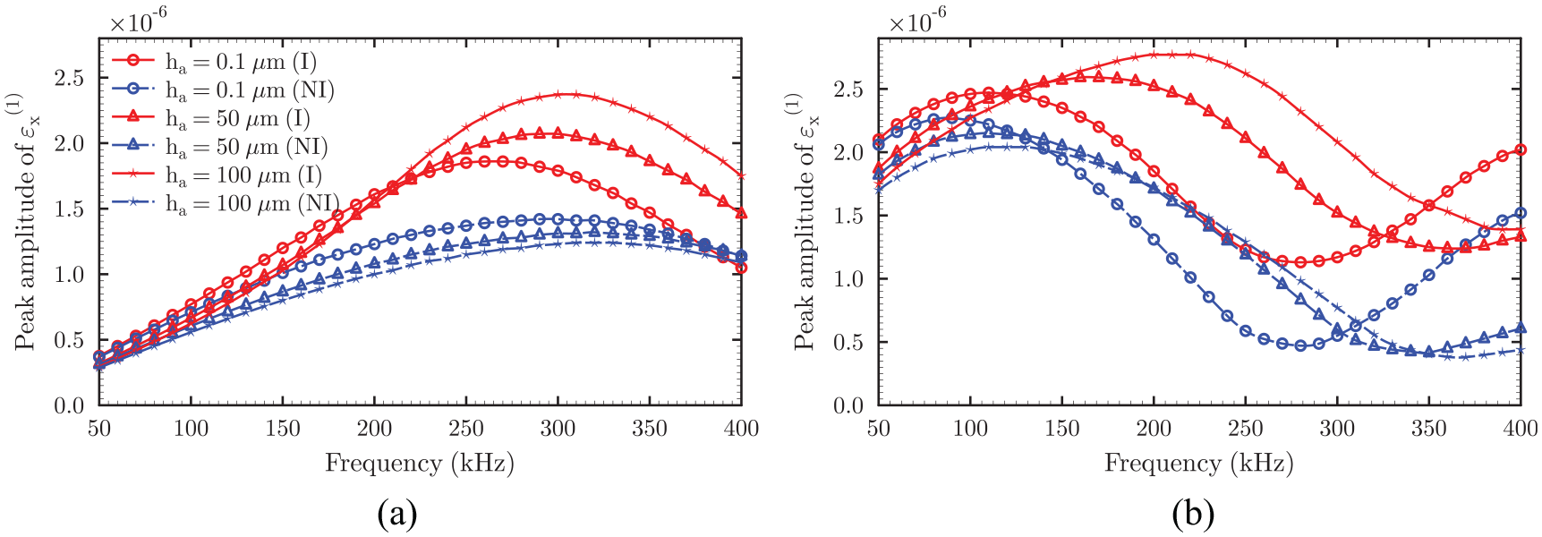
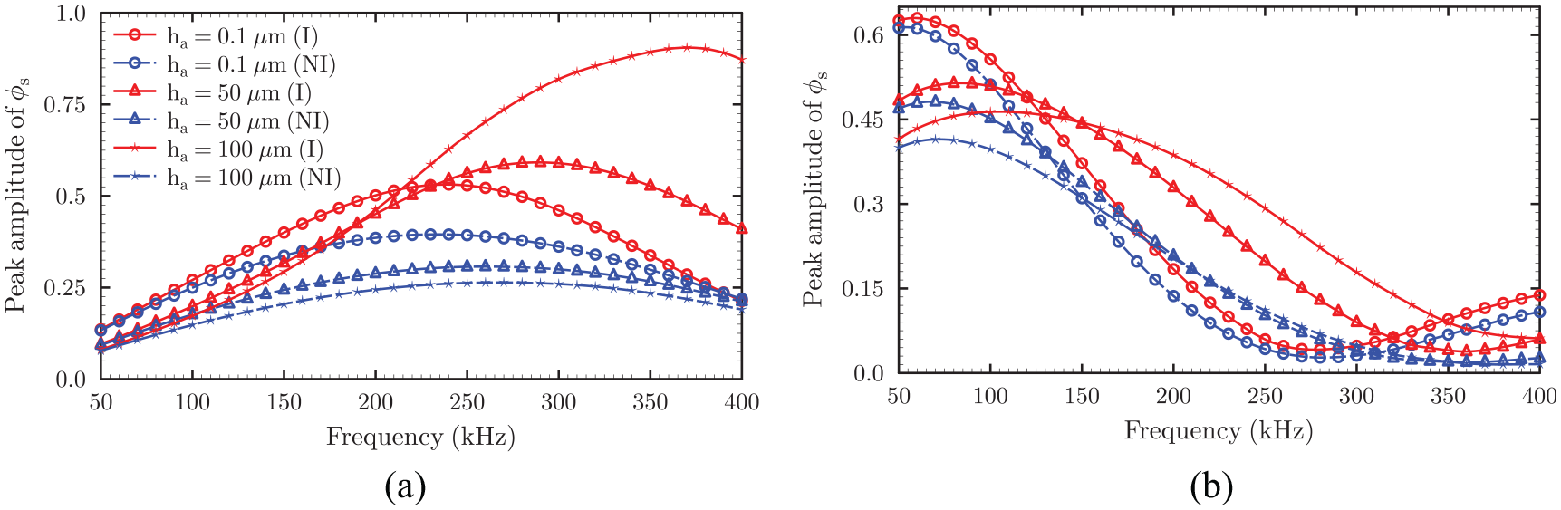
Effect of transducer thickness on inertia effect
The variations of the peak amplitude of the
Effect of transducer thickness on inertia effect on the strain at top surface of the host plate at sensor location (
Effect of transducer thickness on inertia effect on sensor potential: (a)
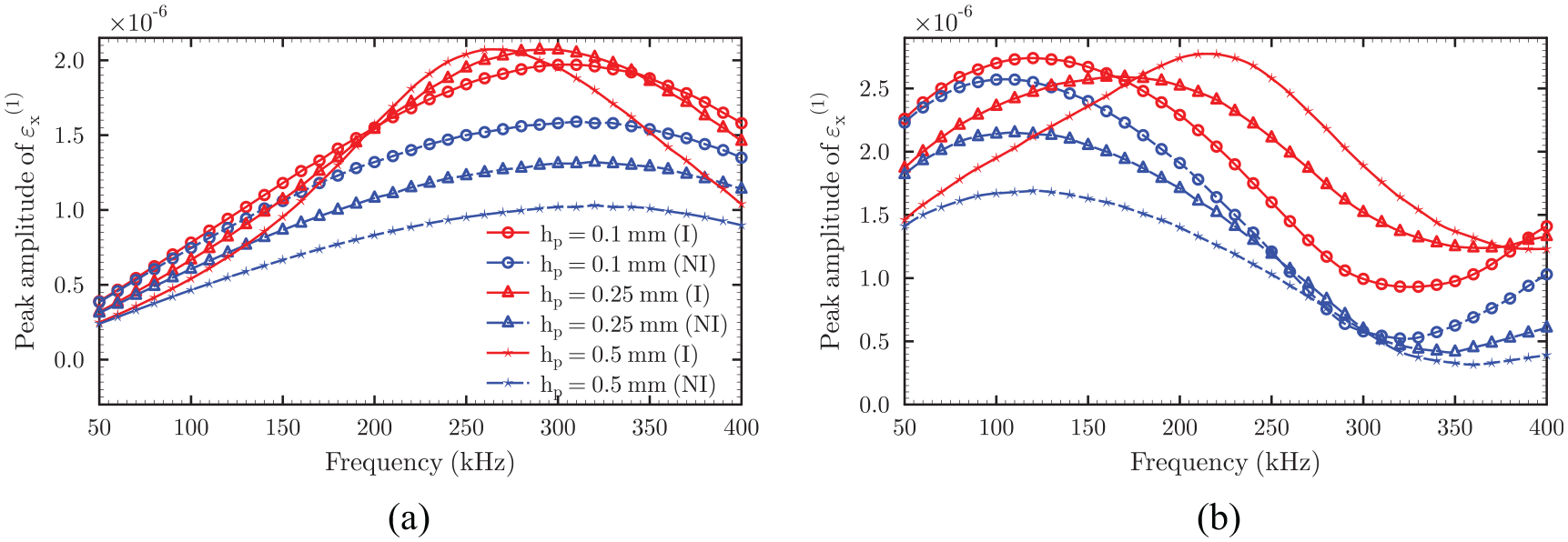
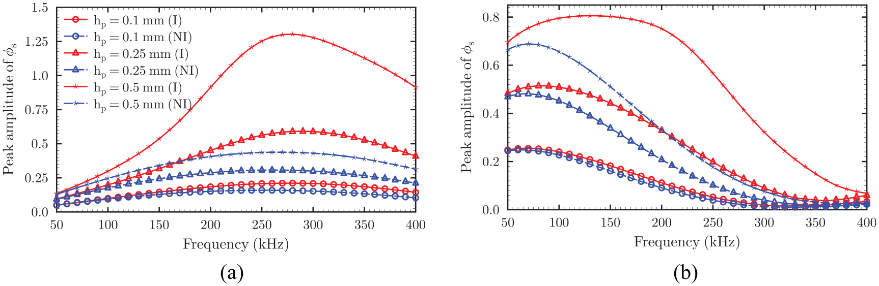
Effect of plate thickness on the inertia effect
The peak amplitude of Lamb strain versus excitation frequency curve for the system with plate thickness of 1.5 and 3 mm are compared in Figure 14, for
Effect of plate thickness on inertia effect on the strain at top surface of the host plate at sensor location (
Effect of plate thickness on inertia effect on sensor potential: (a)
Effect of inertia on time reversibility
To study the effect of inertia on time reversibility, the percent similarity of the reconstructed signal after TRP obtained using the present model with the original input signal is plotted in Figure 16 as a function of the central excitation frequency, considering (i) the system inertia, (ii) only plate inertia, and (iii) no inertia. The inclusion of the plate inertia improves the time reversibility at all frequencies within the probed frequency range. But, when the transducer inertia is also added, the improvement occurs only over a certain range of frequency, beyond which the percent similarity drops. The frequency at which the percent similarity is maximum (called best reconstruction frequency) shifts leftward from 115 kHz when the system inertia is included to 85 kHz when only the plate inertia is included and to 74 kHz when inertia is neglected. In recent studies (Agrahari and Kapuria, 2016a, 2016b), the best reconstruction frequency
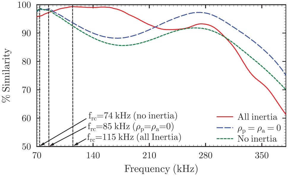
Effect of inertia on time reversibility of Lamb wave induced electric potential.
To appreciate the time reversibility of Lamb wave at different frequencies, the main mode waveform of the normalized reconstructed signal is compared with the normalized input signal in Figure 17 for the best reconstruction frequency (115 kHz) and two other values of frequency, 180 and 350 kHz. The results are presented for both full inertia and no inertia cases. The deviation of the reconstructed waveform from the original input signal, caused by the amplitude dispersion, is clearly the least at the best reconstruction frequency and in tune with the percent similarity (Figure 16).
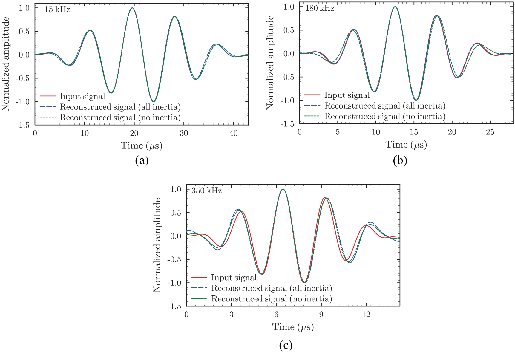
Comparison of reconstructed signal with original input signal for: (a) 115 kHz (best reconstruction frequency), (b) 180 kHz, and (c) 350 kHz excitation frequency.
Effect of adhesive layer thickness on inertia effect on
Figure 18 shows the variation of the best reconstruction frequency (
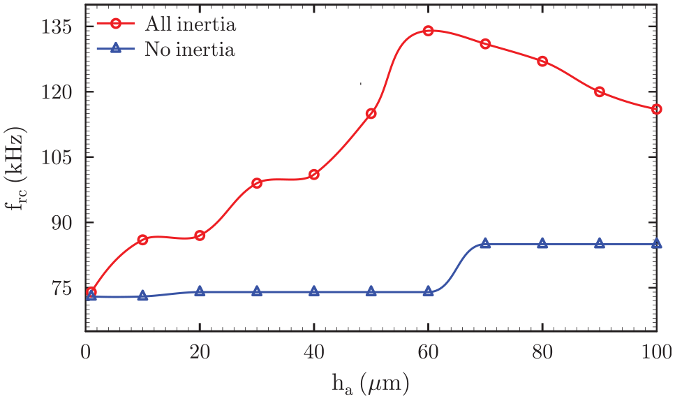
Variation of best reconstruction frequency with adhesive layer thickness.
Effect of transducer thickness on inertia effect on
The variations of the best reconstruction frequency
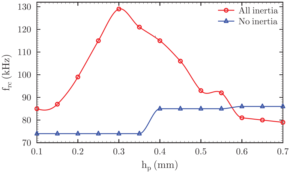
Variation of best reconstruction frequency with PZT thickness.
Effect of transducer length on inertia effect on
The system inertia greatly influences the nature of dependency of the best reconstruction frequency on transducer length as well (Figure 20). The best reconstruction frequency shows a monotonic decrease with the increase in the transducer length (
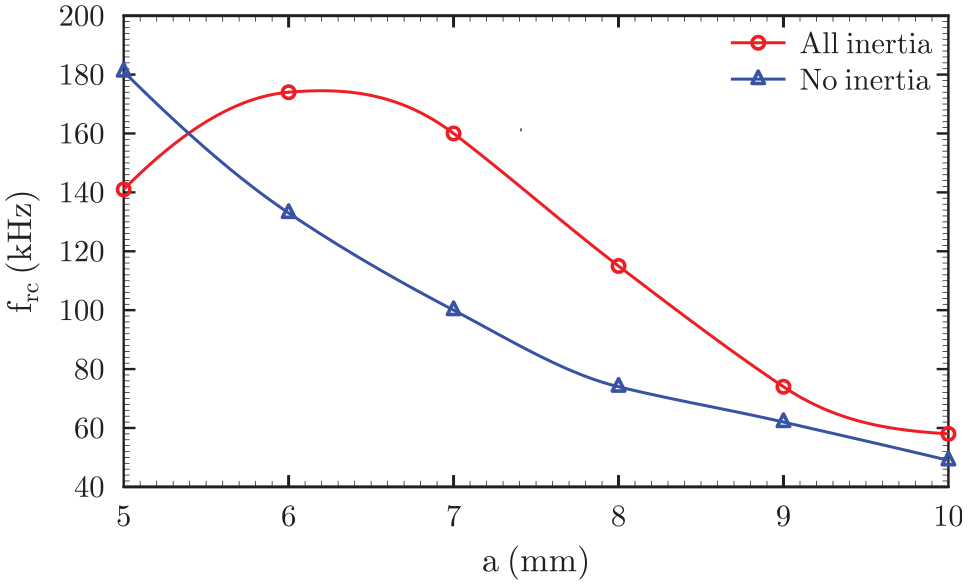
Variation of best reconstruction frequency with PZT length.
Effect of plate thickness on inertia effect on
When the inertia of the system is not taken into account, the best reconstruction frequency shows a monotonous increase with the increase in the plate thickness (Figure 21). However, when the inertia effect is considered, the best reconstruction frequency reaches the maximum at a plate thickness of 4 mm and decreases thereafter.
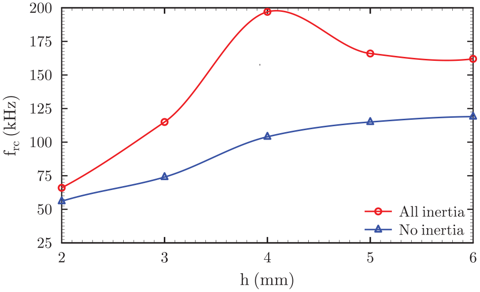
Variation of best reconstruction frequency with plate thickness.
Conclusions
An analytical model has been developed for actuation and sensing of Lamb waves in an isotropic plate with surface-bonded transducers under plane strain assumption, considering the shear-lag effect due to the bonding layer as well as the inertia effects of all constituents in transducer modeling. For this purpose, a consistent sensor-plate interaction model considering the aforementioned effects and satisfying the boundary conditions of the sensor has been developed for the first time. A closed-form solution is obtained in the frequency domain for the forward response and the TRP. The time domain response is obtained by employing the inverse Fourier transform. The new model has been validated in comparison with the 2D FE analysis and the experimental data. A detailed parametric study is conducted to ascertain the effect of inertia on the forward and reconstructed response after the TRP. The numerical study has revealed the following:
The present analytical solution considering inertia effects shows very good agreement with the detailed 2D FE analysis results for the Lamb strain in the plate and the sensor potential for both
The omission of inertia terms, on the other hand, resulted in significant errors in the peak amplitudes of Lamb strain and the sensor potential for both symmetric and antisymmetric modes for excitation frequencies greater than 100 kHz.
The inclusion of system inertia in the transducer models has a large influence on both
The transducer inertia has the most significant effect on Lamb wave response for both the symmetric and antisymmetric modes, followed by the plate inertia. As expected, the adhesive layer inertia has a minimal effect even at high excitation frequencies. The system inertia affects also the excitation frequency corresponding to maximum peak amplitude of both the fundamental modes of the Lamb strain and the sensor potential response.
The increase in both adhesive layer and transducer thickness significantly enhances the inertia effect on the peak
Contrary to the effect of adhesive layer thickness and transducer thickness, an increase in the plate thickness causes a reduction in the relative effect of inertia on the Lamb strain and sensor potential response for the
The time reversibility of Lamb waves improves on the inclusion of plate inertia over the probed frequency range, whereas the similarity drops for certain frequencies when the transducer inertia is added.
At the best reconstruction frequency, however, the similarity of the reconstructed signal seems to always increase with the inclusion of transducer inertia.
In the absence of the inertia effect, the adhesive layer thickness and the transducer thickness show only marginal influence on the best reconstruction frequency. However, when the system inertia is included, the best reconstruction frequency shows a strong dependency on the adhesive layer thickness as well as the transducer thickness, which reaches a peak at a certain value of both the thickness parameters.
The best reconstruction frequency shows strong dependency on the transducer length and the plate thickness, irrespective of inclusion and omission of the system inertia. However, the nature of the variation changes from a monotonic one in absence of inertia effect to having a peak in its presence.
Finally, the developed closed-form solution will be of immense use to the design of Lamb wave based SHM systems with and without using baseline signals.
Footnotes
Declaration of conflicting interests
The author(s) declared no potential conflicts of interest with respect to the research, authorship, and/or publication of this article.
Funding
The author(s) disclosed receipt of the following financial support for the research, authorship, and/or publication of this article: S. Kapuria acknowledges the financial support provided for this study by the Science & Engineering Research Board, Department of Science and Technology, Government of India through J. C. Bose National Fellowship (Grant No. JCB/2018/000025).