
Abstract
An Extended Layerwise/Solid-Element (XLW/SE) method is developed based on the Extended Layerwise method (XLWM) and eight-node solid element method for the static analysis of damaged composite sandwich structures with piezoelectric sensor. In this method, the XLWM is used to model the facesheets and piezoelectric sensors, and the eight-node solid element is used for the lattice. Based on the equilibrium conditions of displacement and internal force of the overlapped joints at the facesheet/sensors and facesheet/lattice interfaces, the general governing equation is established. In the numerical examples, the proposed method is verified by comparing with the 3D elasticity model developed in the commercial finite element software, and composite sandwich plates with delamination and/or transverse crack and/or debonding are analyzed.
Keywords
1. Introduction
Composite sandwich structure has been widely used in various engineering industries, such as aerospace, automobile, civil engineering, marine engineering, etc. The manufacturing process of composite sandwich structure has its own advantages, and more and more researches focus on its mechanical properties. For the analysis and design of composite sandwich structures, it is necessary to obtain the exact solutions of displacement and stress. In recent years, various theories of plates and shells have been applied to the composite sandwich structures. Thai et al. (2013, 2012) extended a high-order shear deformation theory (HSDT) to analyze the composite sandwich plates based on a layerwise deformation theory and multi quadrics discretization. And then, the proposed a generalized shear deformation theory (GSDT) to solve the static, dynamic, and buckling problems of functionally graded sandwich plates Thai et al. (2014). Based on the HSDT and GSDT, the proposed a generalized layerwise HSDT for composite sandwich plates Thai et al. (2016). The continuity of interlaminar displacement and transverse shear stress was ensured. Recently, Thai et al. (2017, 2018) developed a naturally stabilized nodal integration meshfree formula and a layerwise
On the basis of the above analysis methods, some researchers developed the modified method to improve the calculation accuracy. Khalili et al. (2014) developed a global-local theory with three-dimensional elastic correction for stress and deformation analysis of multilayer sandwich plates. Chalak et al. (2012) proposed an improved
With the wide application of piezoelectric material in the composite sandwich structures, whether the piezoelectric patch is used as a driver or a monitor, their coupling analysis becomes very significant. Torres and Mendonca (2010) carried out a numerical analysis of the coupled electro-structural response of orthotropic fiber reinforced layers and piezoelectric layers composite laminates based on generalized finite element method. Based on the HSDT, Torres et al. (2011) established the bending analysis formula of piezoelectric laminates by using generalized finite element method. Electric potential was interpolated by using the LWT and a mixed model was obtained by kinematic hypothesis. Chrysochoidis and Saravanos (2007) proposed a coupled linear layerwise laminate theory and beam finite element analysis method for analyzing delaminated composite beams with piezoelectric structures. The zig-zag fields were adopted for axial displacement and electric potential. The discontinuity in the displacement field caused by delamination was taken as additional freedom in this method. Plagianakos and Papadopoulos (2015a, 2015b) presented a coupled higher-order layerwise method for the piezoelectric laminates. It was applicable to shallow cylindrical composite and sandwich shells subjected to static mechanical loads and/or electric voltages. Based on an electromechanically coupled third order zigzag theory, Ahmed and Kapuria (2020) presented an efficient four-node face shell element for analysis of doubly curved multilayered piezoelectric shells. Yasin et al. (2020) presented a two-node efficient finite element model. The model incorporated the layerwise mechanics for the dynamics and active vibration control of smart functionally graded beams. Yasin and Kapuria (2014) presented a new efficient four-node finite element for shallow multilayered piezoelectric shells by considering layerwise mechanics and electromechanical coupling. The hybrid shells were made of single-material composite substrates and sandwich substrates with a soft core. The semi-layerwise analysis, the first- and second-order shear and normal deformation as well as the third-order shear deformation theories were applied to analyze structural sandwich plates with through-width delamination and delaminated sandwich shells having constant radii of curvatures by Szekrenyes (2018, 2020), and the governing equations were derived from the virtual work principle. In our previous research Xu et al. (2019), an electromechanical coupling model was presented for the piezoelectric laminates based on XLWM.
The existing research is mainly focused on piezoelectric material and composite sandwich plates without damage. There is few method on damaged composite sandwich plates with piezoelectric sensors and considering the typical damage such as, delamination, transverse cracks and debonding. The bonding quality of the piezoelectric structure and the damage of the main structure make the coupling analysis process more complicated. It is necessary to pay attention to the influence of damage and debonding on the electric potential of the piezoelectric structure. Therefore, Li et al. (2015); Li and Fish (2018); Li (2016b); Liu et al. (2016); Li (2016a); Li and Zhang (2017) established an extended layerwise method (XLWM) for laminated beams, plates and shells on the basis of layerwise theory and extended finite element method (XFEM). The proposed method can deal with laminated composite plates/shells with multiple delamination and transverse cracks. Then, an extended layerwise/solid-element method (XLW/SE) Li et al. (2013, 2016); Lu et al. (2017) was developed for composite sandwich plates. Based on XLW/SE and electromechanical coupling model, the model of composite sandwich plates with piezoelectric sensor is proposed in the present works. The extended layerwise method is used to establish the governing equations of piezoelectric sensor and facesheets, and the solid element method is used to obtain the governing equation of lattice. The rest of this paper is organized as following. In section 2, based on the XLW/SE, the governing equation of the composite sandwich plates with piezoelectric sensor is obtained by the equilibrium conditions of displacement and internal force. In section 3, the convergence analysis is carried out. Some numerical examples are carried out to verify the proposed methods for the undamaged/damaged composite sandwich plates with piezoelectric sensor. The effects of the delamination, transverse crack on the electric potential responses are investigated, together with the debonding at the facesheet/lattice and facesheet/sensor interfaces. In section 4, some conclusions are drawn.
2. Mathematic formulations
Based on the proposed method, the model in this paper can be divided into three parts: (i) the piezoelectric sensor; (ii) the laminated facesheets; (iii) the lattice. The part (i) and (ii) are discretized with XLWM, and the part (iii) is simulated based on the eight-node solid element (SE) method. All the three parts are combined by considering the compatibility of displacements and the equilibrium of internal force, namely, the XLW/SE method.
2.1. Extended layerwise method of the piezoelectric sensor and laminated facesheets
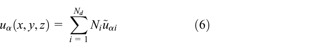
As shown in Figure 1(a), based on XWLM, the displacements and electric potential of the piezoelectric sensor with multiple delaminations is expressed as Xu et al. (2019)
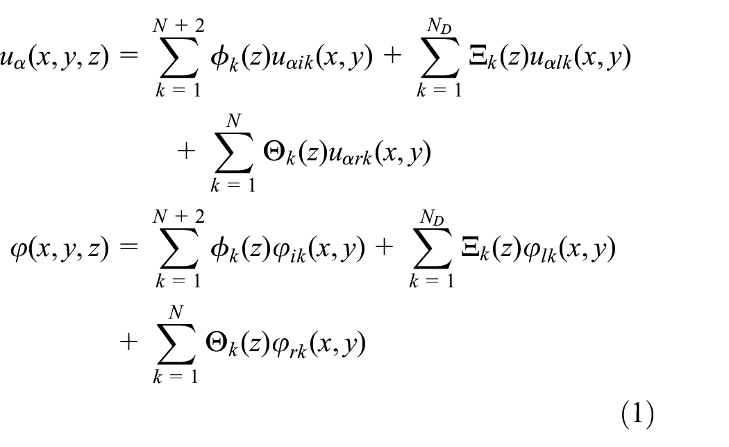
where
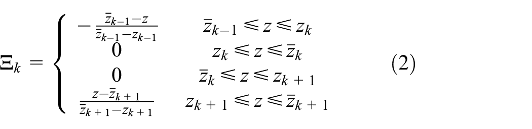
where
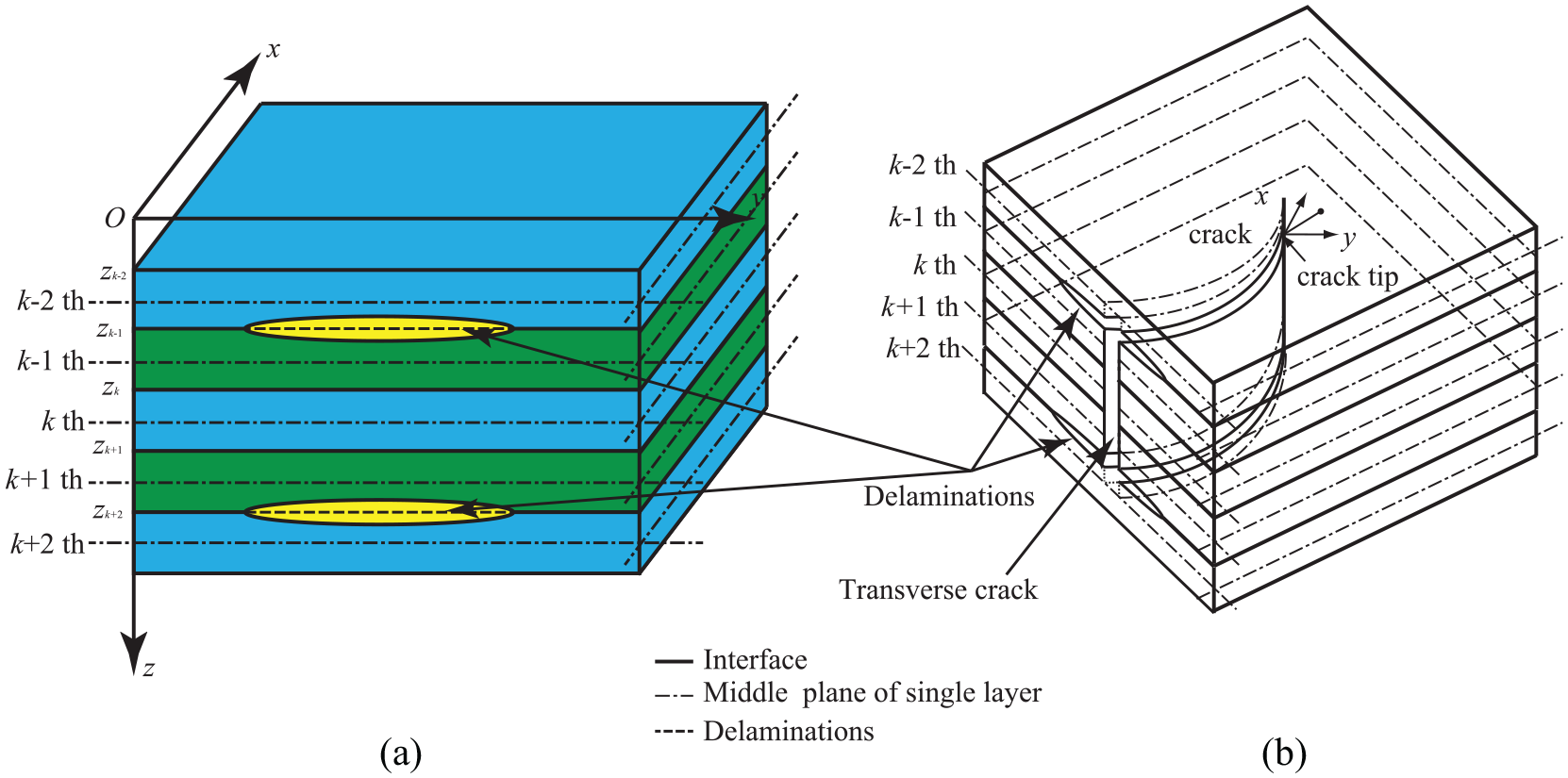
The damage modes of XLWM. (a) laminated composite plates with multiple delaminations; (b) details of the transverse crack.
As shown in Figure 1(b), for the laminated piezoelectric plates with multiple delaminations and transverse cracks, the standard and enrichment degrees-of-freedom are expressed over each element as a linear combination of two-dimensional Lagrange interpolation function, discontinuous enrichment functions and branch function. The displacement and electric potential fields can be rewritten as
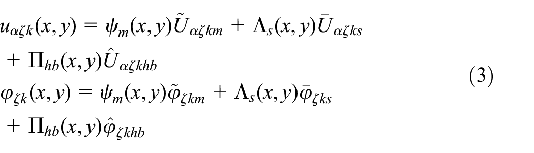
where
Based on virtual displacement principle, for static problem of piezoelectric sensor with multiple delaminations and transverse cracks, the finite element equations are given by

where
Similarly, the laminated facesheets with delamination and transverse crack is given by

2.2. Eight-node solid element method of lattice
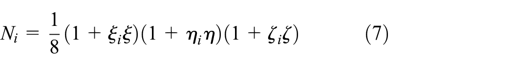
The governing equations of the lattice are established by the three-dimensional solid finite element method. The hexahedral eight-node solid element is used to analyze the lattice and the displacement is expressed as
where
Based on the principle of virtual work, we can obtain the governing equation of the lattice as follows
where
2.3. XLW/SE of composite sandwich plate with piezoelectric sensor
As shown in Figure 2, there are three conditions to ensure the compatibility of displacements and the equilibrium of internal force between the piezoelectric sensor/upper facesheet, the upper facesheet/lattice interfaces and the lattice/lower facesheets interfaces. The governing equation of the piezoelectric sensor, upper facesheet, lattice and lower facesheets must be rewritten as equations (8)–(11).
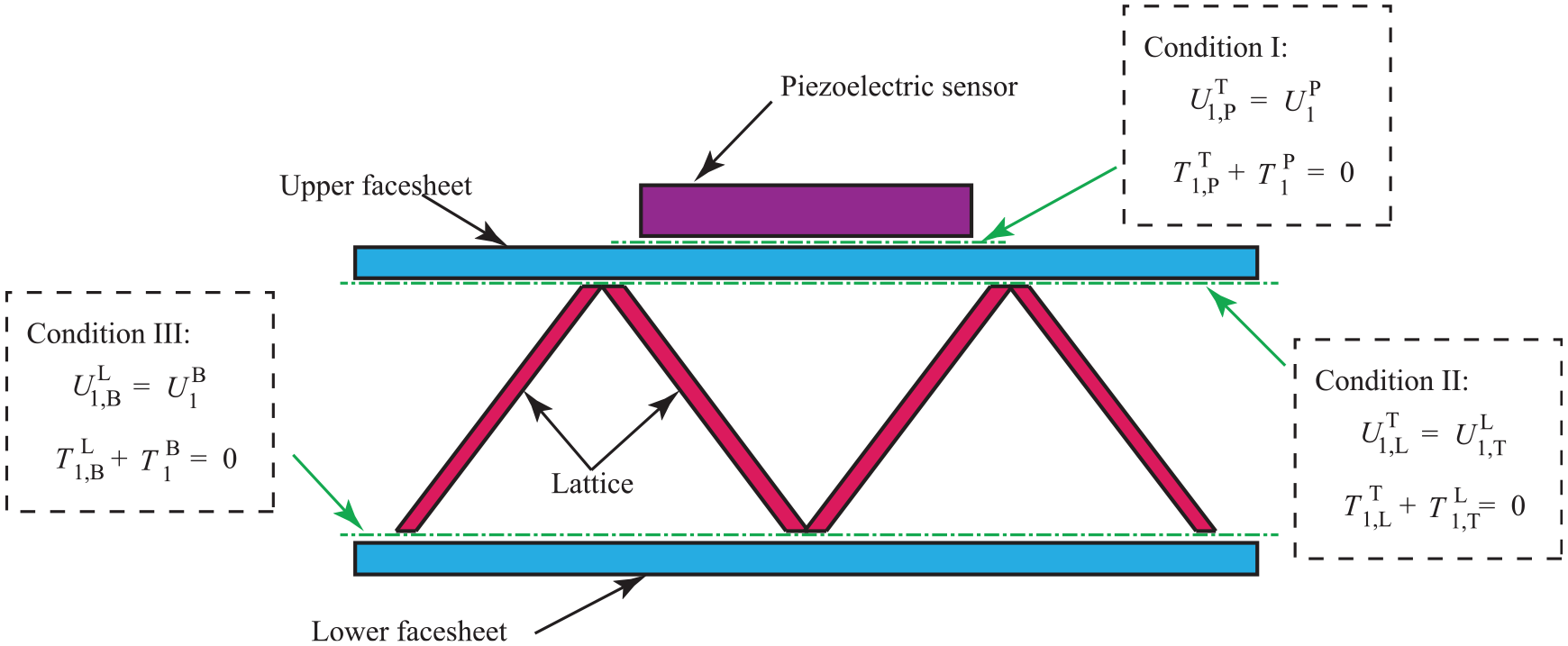
XLW/SE method for the composite sandwich structures with piezoelectric sensor.
According to Condition I, all of the displacements variables of the piezoelectric sensor can be divided into two groups: displacement vectors connected to the upper facesheet, displacement vectors not connected to the upper facesheet. Therefore, the governing equation of the piezoelectric sensor can be rewritten as
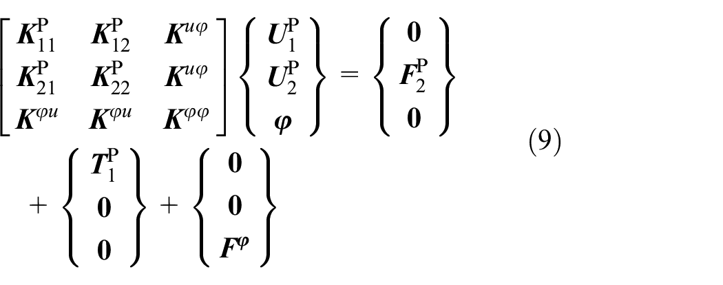
where the subscripts 1 and 2 denote the internal variables vector and external variables vector, respectively.
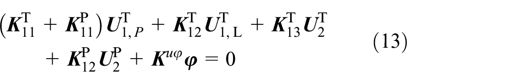
According to Condition I and II, all of the displacements variables of the upper facesheet can be divided into three groups: displacement vectors connected to the piezoelectric sensor, displacement vectors connected to the lattice and displacement vectors not connected to the piezoelectric sensor and lattice. The governing equation of the upper facesheet can be written as
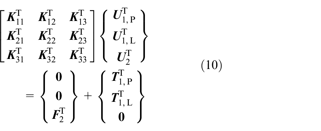
where meanings of the subscripts 1 and 2 are the same as the equation (8), the subscripts P, L and superscript T denote the piezoelectric sensor, lattice and upper facesheet, respectively.
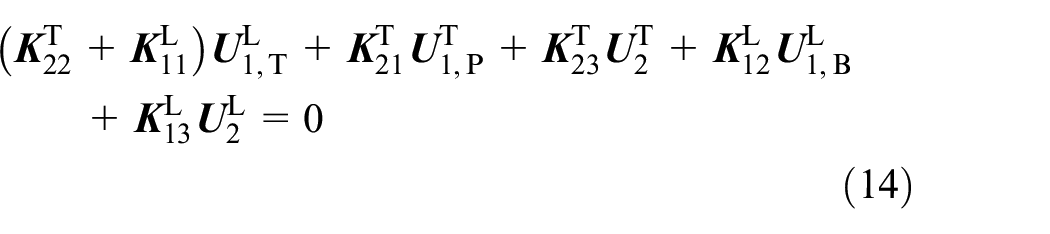
In the same way, all of the displacements variables of the lattice can also be divided into three groups according to Condition II and III. The form is the same as equation (8). The governing equation of the lattice can be rewritten as
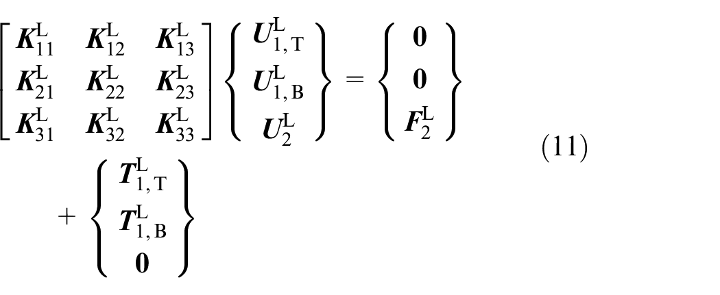
where the subscripts T, B and superscript L denote the upper facesheet, lower facesheet and lattice, respectively.
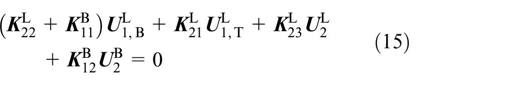
According to Condition III, the governing equation of the lower facesheet can be rewritten as
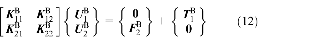
where the subscripts 1 and 2 are the same as the equation (8),
According to the compatibility and internal force condition I (
Based on condition II (
According to condition III (
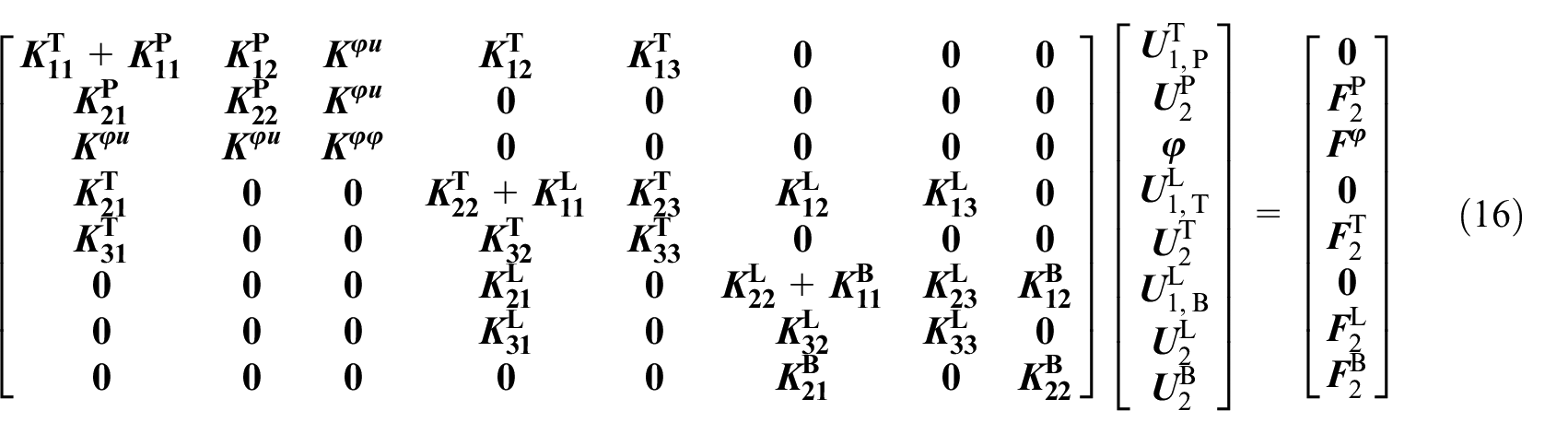
Combining the second and third row of equation (8), the third row of equation (9), the third row of equation (10) and the second row of equation (11), the final governing equation of the composite sandwich structure with piezoelectric sensor can be expressed as
3. Numercial analysis
3.1. Composite sandwich structure without damage
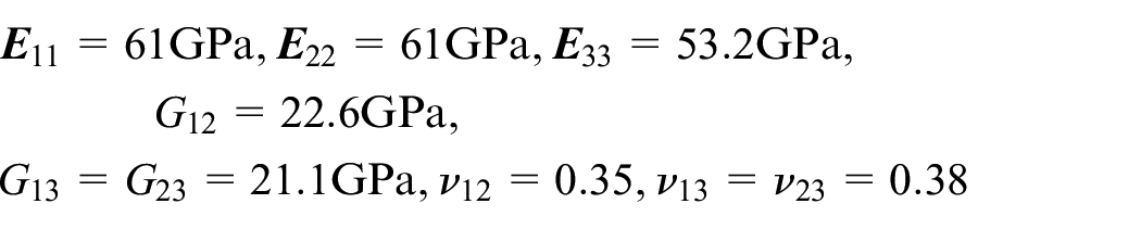
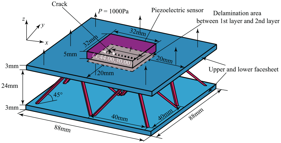
The proposed method is verified by considering the composite sandwich structure without damage as the research object. The geometric dimensions are shown in Figure 3(a). The material properties are taken as:
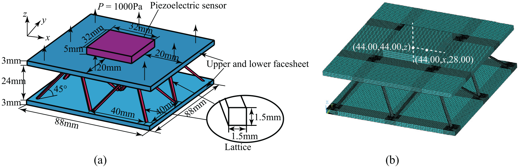
Composite sandwich structure with piezoelectric sensor. (a) Schematic; (b)Meshing in 3D elasticity model.
Elastic constants of facesheets:

Elastic constants of piezoelectric sensor:
Piezoelectric constants:

Dielectric constants:

Elastic constants of Lattice:

A 3D elasticity model developed in the commercial finite element software is employed to verify proposed XLW/SE method. SOLID5 and SOLID185 are employed to simulate the piezoelectric sensor and composite sandwich structure in 3D elasticity model, respectively. Four edges of the composite sandwich plates are clamped. The electric potential of four edges of the piezoelectric sensor is constrained. The facesheets and piezoelectric sensor are uniformly divided into three mathematical layers and four mathematical layers in the thickness direction, respectively. The stacking sequence of facesheets and piezoelectric sensor are taken as: [0/0/0] and [0/0/0/0], respectively. Three meshing schemes of piezoelectric sensor are considered:
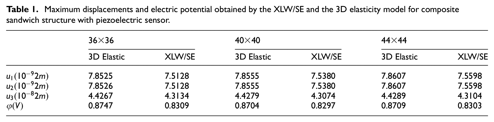
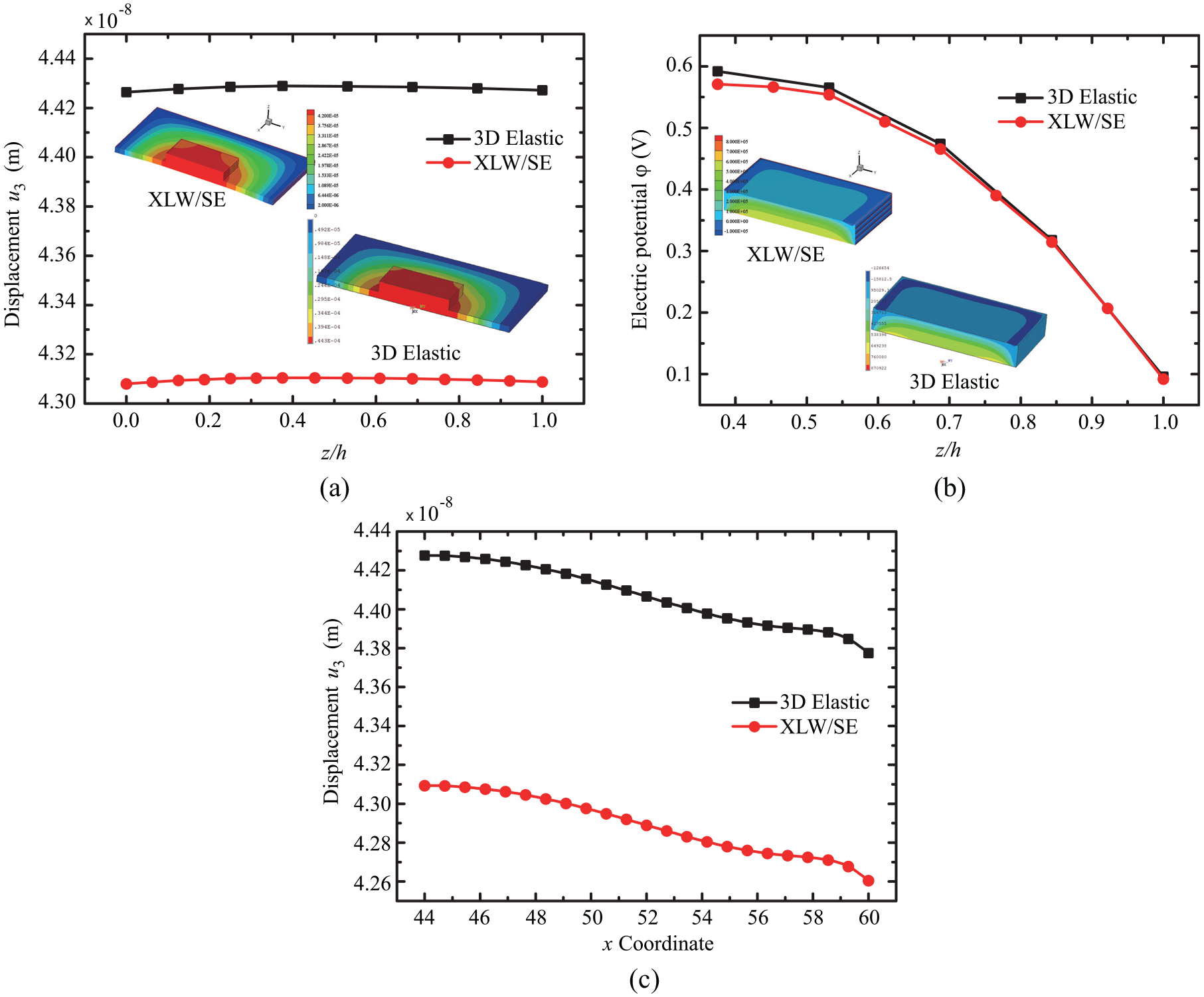
The maximum displacements and electric potential of different meshing schemes calculated by the XLM/SE and the 3D elasticity model are compared in Table 1. The results of the displacements and electric potential have converged when the meshing scheme is taken as
Maximum displacements and electric potential obtained by the XLW/SE and the 3D elasticity model for composite sandwich structure with piezoelectric sensor.
Displacement
3.2. Debondings between the composite sandwich plates and piezoelectric sensor
First of all, the debondings between the composite sandwich plates and piezoelectric sensor is considered. The electric potential of the piezoelectric sensor are changed by damage. The debonding at the upper facesheet/sensor interface are shown in Figure 5. Two different debonding regions are considered:
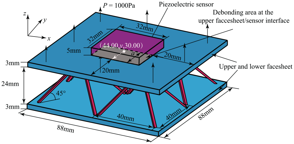
Composite sandwich structure with debonding at the upper facesheet/sensors interface.
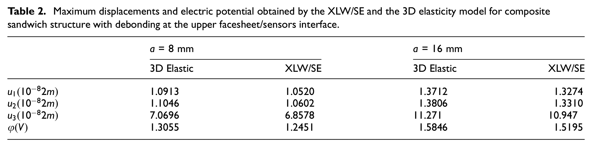
Maximum displacements and electric potential obtained by the XLW/SE and the 3D elasticity model for composite sandwich structure with debonding at the upper facesheet/sensors interface.
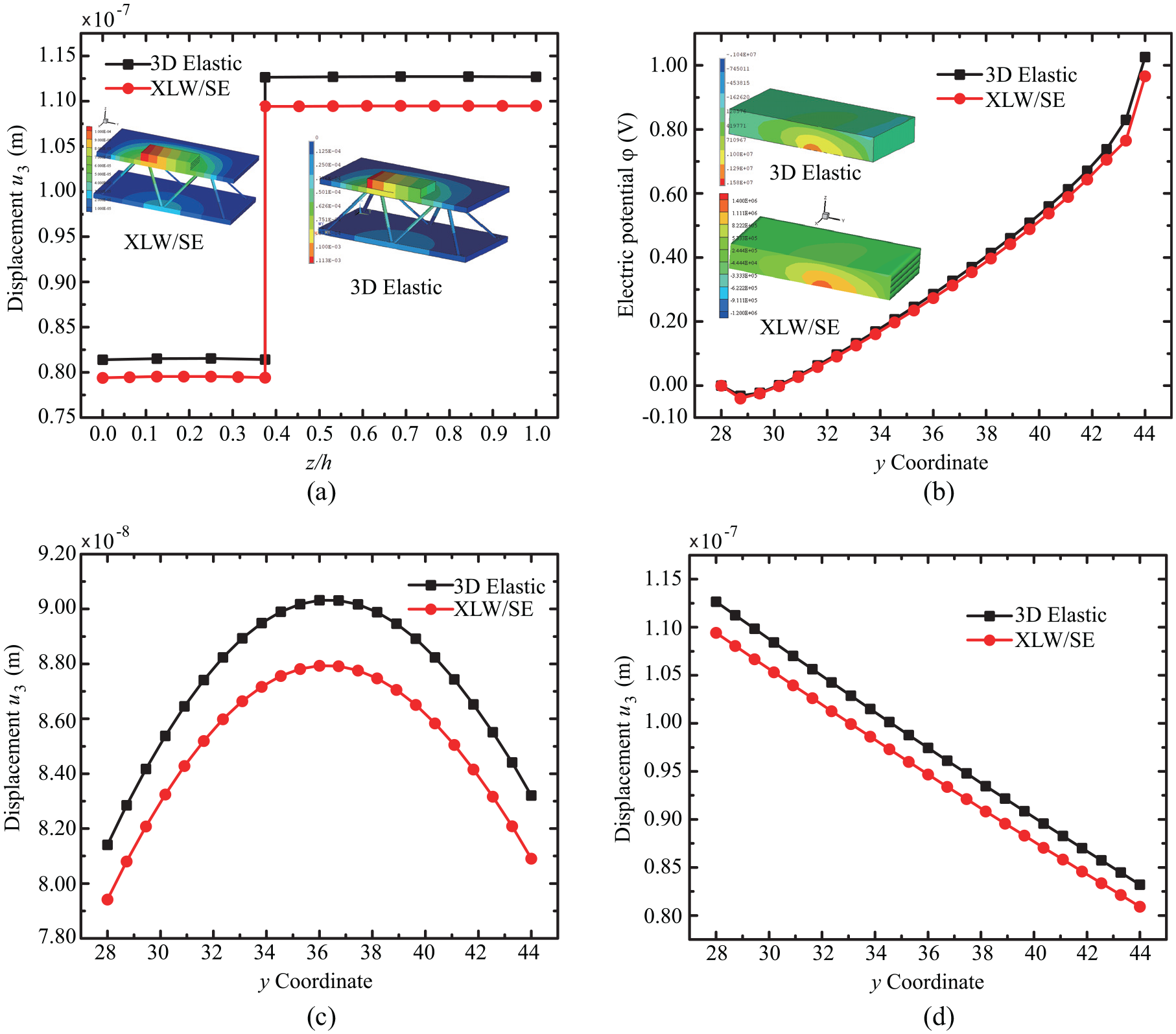
Distribution of displacements and electric potential of composite sandwich structure with debonding at the upper facesheet/sensors interface (
The proposed method can deal with the debondings at the facesheet/sensor interface. The results are in good agreement with those obtained by the 3D elasticity model. Compared with Table 1, the debonding at the upper facesheet/sensors interface has a great impact on the electric potential of the piezoelectric sensor, and the electric potential increases with the increase of the debonding area.
3.3. Delamination or/and transverse crack in facesheets
Delamination or/and transverse crack are two common damage forms of facesheet and these can be considered by the proposed method. Firstly, only the delamination damage is considered. The location of delamination area are shown in Figure 7. The geometric dimension of two different delamination areas are
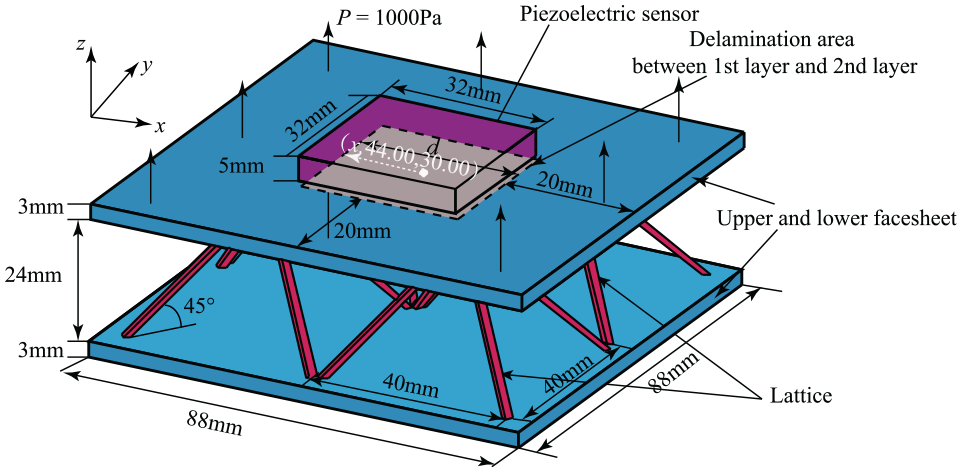
The schematic of the composite sandwich structure with delamination.
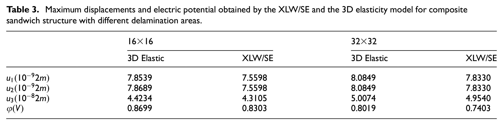
Maximum displacements and electric potential obtained by the XLW/SE and the 3D elasticity model for composite sandwich structure with different delamination areas.
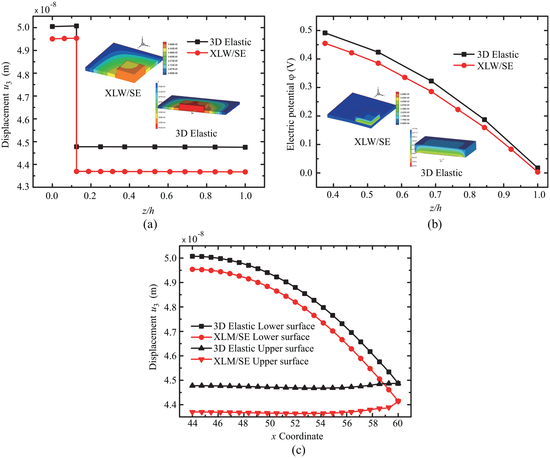
Distribution of displacements and electric potential of composite sandwich structure with delamination areas (
It can be seen from Table 3 and Figure 8 that the results calculated by the XLW/SE method are in good agreement with those of the 3D elasticity model. Compared with the sandwich plate without damage in Table 1, the electric potential gradually decreases with the increase of delamination area. The corresponding distribution of electric potential will change as well. The deterioration of delamination can be detected by this changes. The convergence of the incompatible elements converge is faster than that of linear elements. The number of elements needs to be further increased to ensure that the results calculated by the proposed method are closer to those of the 3D elasticity model. It will inevitably increase the number of calculation. Therefore, the proposed model does not further increase the number of elements after the results are calculated to converge by the XLW/SE, and the result of this method in Figure 8 is larger than that of 3D elasticity model.
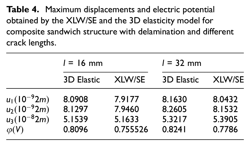
Next, we consider composite sandwich structures with delamination and transverse crack. The geometric sizes are shown in Figure 9. The delamination position and load are the same as the sandwich structures in Figure 7. The through-thickness transverse crack is located in the center of the upper facesheet. The lengths of the crack are taken as 16 and 32 mm, respectively. Since the proposed method requires the crack and crack tip cannot coincide with the mesh line and node, the tip coordinates of crack with length 16 mm are (36.001, 44.001) and (51.999, 44.001), and those of crack with length 32 mm are (28.001,44.001) and (59.999, 44.001). The maximum displacements and electric potential obtained by the XLW/SE and the 3D elasticity model are shown in Table 4. Taking a transverse crack length of 32 mm as an example, the displacement
Composite sandwich structure with delamination and transverse crack.
Maximum displacements and electric potential obtained by the XLW/SE and the 3D elasticity model for composite sandwich structure with delamination and different crack lengths.
Distribution of displacements and electric potential of composite sandwich structure with delamination and transverse crack (
As shown in Table 4 and Figure 10, the results calculated by the XLW/SE method are in good agreement with those of the 3D elasticity model. The proposed method can be used to analyze composite sandwich plates with delamination and transverse cracks. By comparing with Table 4 and Figure 8, the further changes in electric potential are due to the occurrence of transverse cracks in the case where delamination has already occurred. The electric potential increases with the increase of transverse cracks. And the distributions considerably change. Therefore, the proposed method can provide a numerical solution for the coupled analysis of composite sandwich structure and piezoelectric structure. Contact phenomenon is not considered in this proposed method. Therefore, the designed boundary conditions and loads can cause the deformation to be in an open form. It also prevents the meshes from embedding each other.
3.4. Debonding and fracture in lattice
Now, we consider the lattice under the damage. In general, the damage forms of lattice are debonding or fracture. The problems of debonding at the lattice/lower-facesheet interface are calculated by the proposed method and 3D elasticity model, respectively. The schematic are shown in Figure 11. Two cases are considered depending on the different debonding areas: (i) the debonding only occurs at the location No.173 (Case I); (ii) the debonding occurs at the location No.172, 173, 174 (Case II). The four sides of the upper and lower facesheets are clamped, and the lower surface of the lower facesheet is subjected to uniform downward pressure
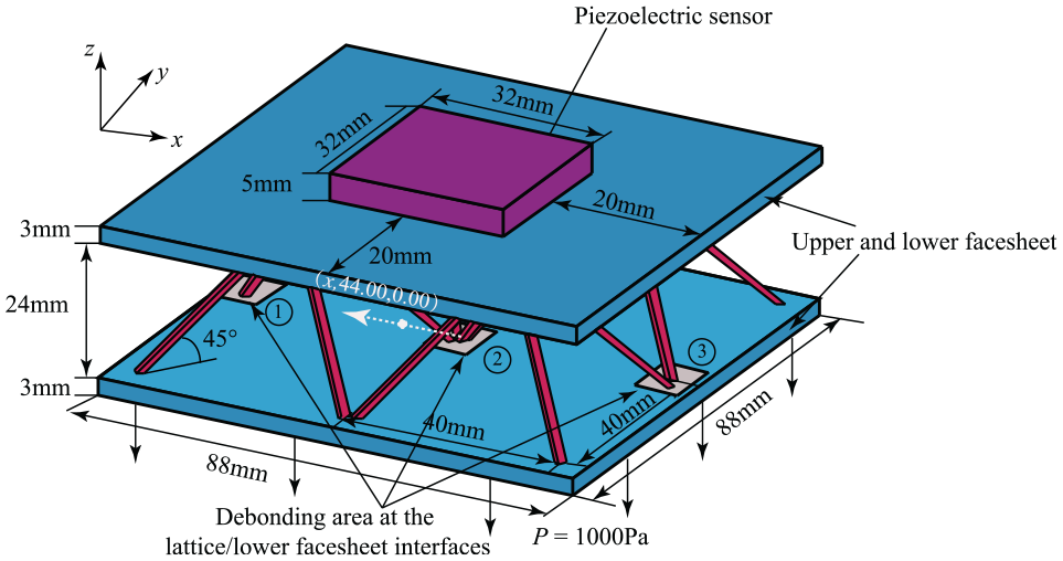
Composite sandwich structure with debonding at the lattice/lower-facesheet interface.
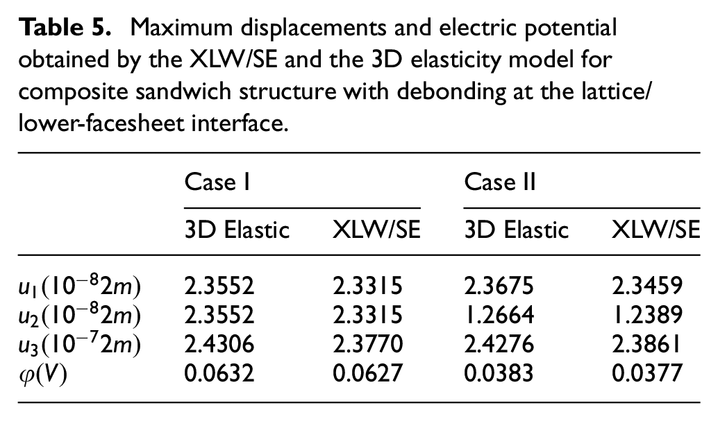
Maximum displacements and electric potential obtained by the XLW/SE and the 3D elasticity model for composite sandwich structure with debonding at the lattice/lower-facesheet interface.
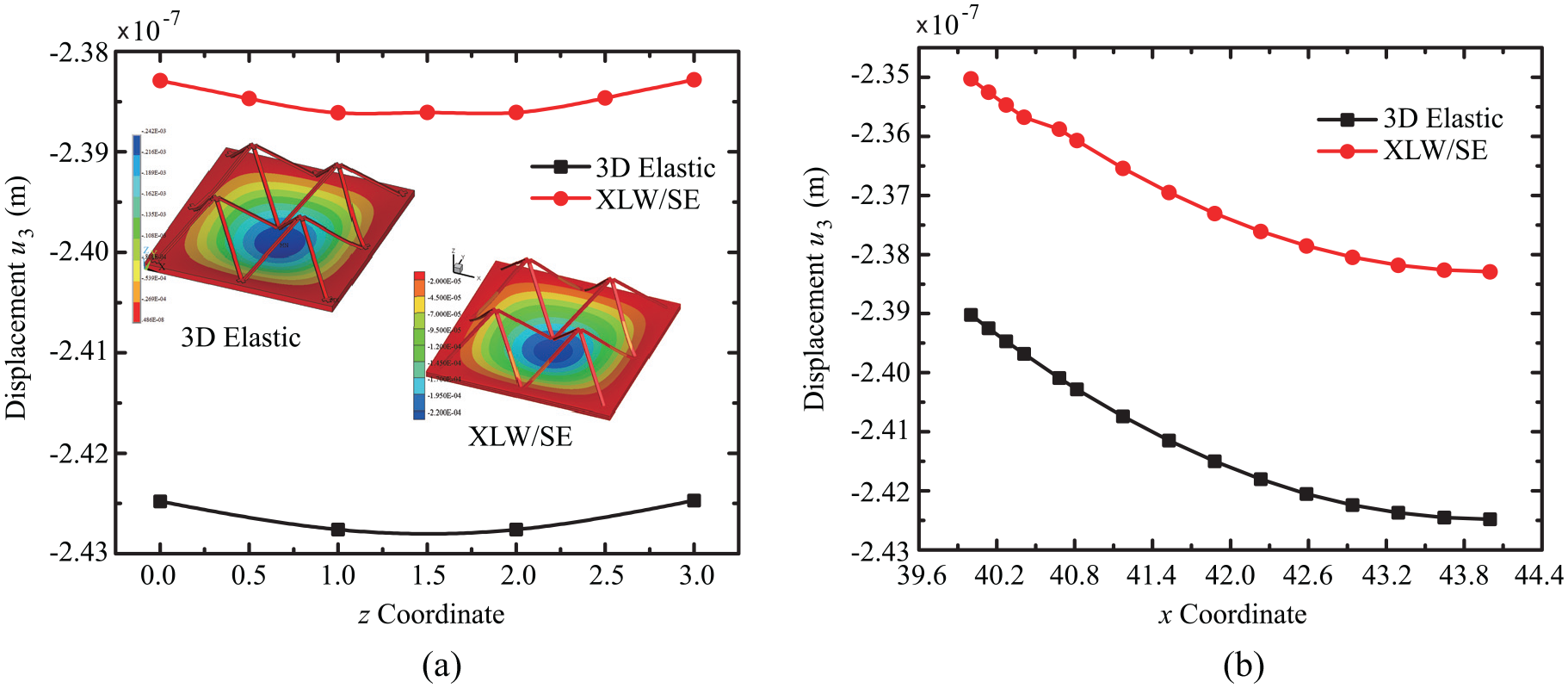
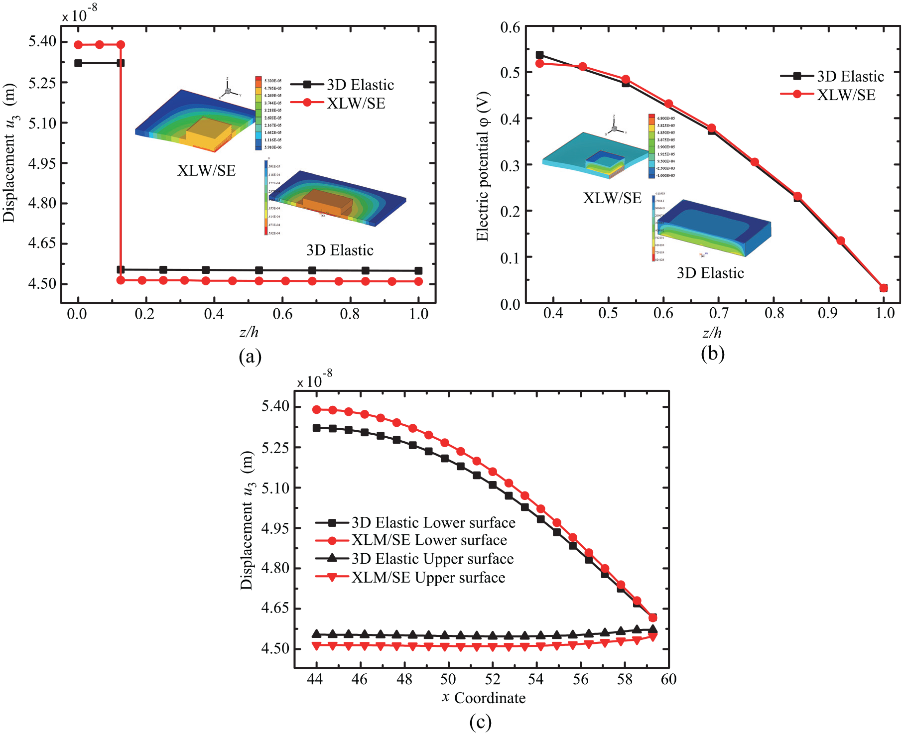
Distribution of displacements and electric potential of composite sandwich structure with debonding at the lattice/lower facesheet interface (Case II). (a) Displacement
The results of the proposed method are consistent with those of 3D elasticity model. Moreover, the results in Table 5 are compared with those in Table 1, the electric potential changes significantly before and after the debondings. As the debonding area increases, the electric potential decreases. Currently, the damage state of the composite lattice structure can easily distinguished by the changes in these parameters.
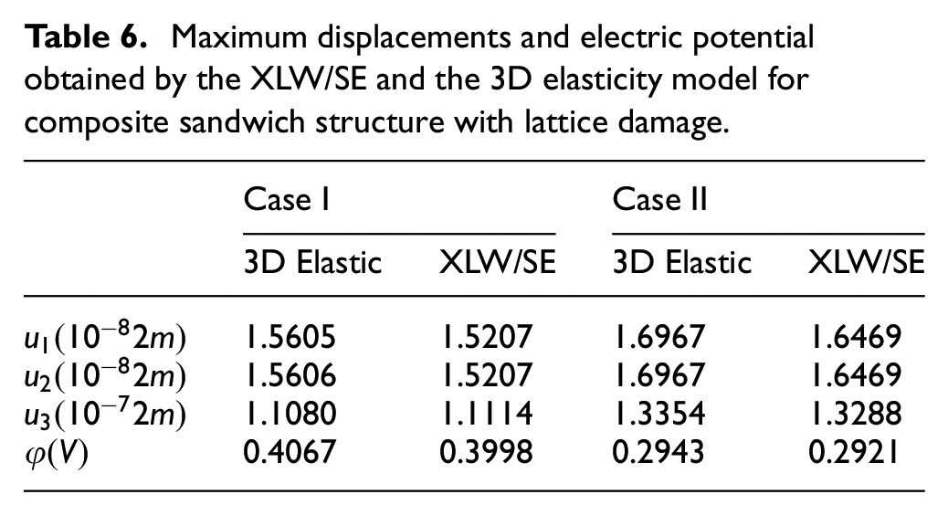
Then, the fracture problem of lattice is studied. The fracture location is shown in Figure 13. Two cases are considered depending on the the number of fractured lattices: (i) lattice No.172 is broken (Case I); (ii) Lattice No.172 and 173 are broken (Case II). The boundary conditions and loads are the same in Figure 11. Maximum displacements and electric potential obtained by the XLW/SE and the 3D elasticity model are compared in Table 6, and the comparison of displacements and electric potential distribution is shown in Figure 14.
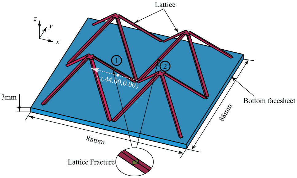
Composite sandwich structure with lattice fracture damage.
Maximum displacements and electric potential obtained by the XLW/SE and the 3D elasticity model for composite sandwich structure with lattice damage.
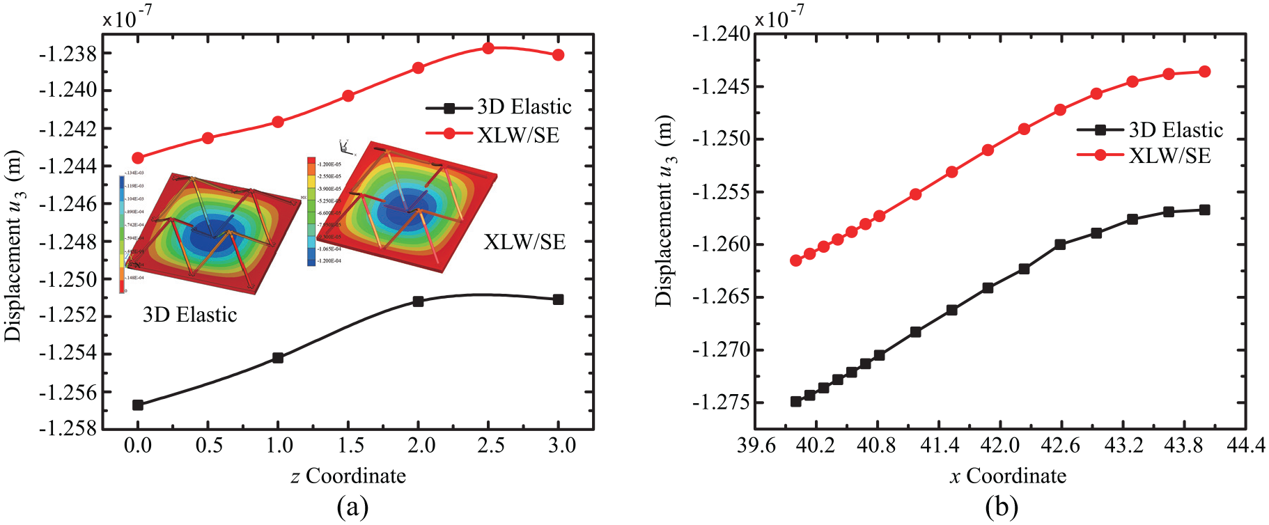
Distribution of displacements and electric potential of composite sandwich structure with lattice fracture (Case II). (a) Displacement
Similarly, the proposed method is very suitable for the problem of lattice fracture, and the results from proposed method are in good agreement with those from 3D elasticity model. The number of the lattice fractures is an important factor affecting the electric potential in the coupled analysis.
3.5. Composite sandwich structure with multiple damages at different positions
At the end of this section, the composite sandwich structure with multiple damages at different positions are considered. The geometric sizes and locations of various damage are shown in Figure 15. The delamination area is a square with a side length of 32 mm and is marked as a gray area. The crack length is 16 mm, and the crack tip coordinates are (36.001, 44.001) and (51.999, 44.001). The green area denotes the debonding area. The upper and lower facesheets are subjected to uniform upward and downward pressure
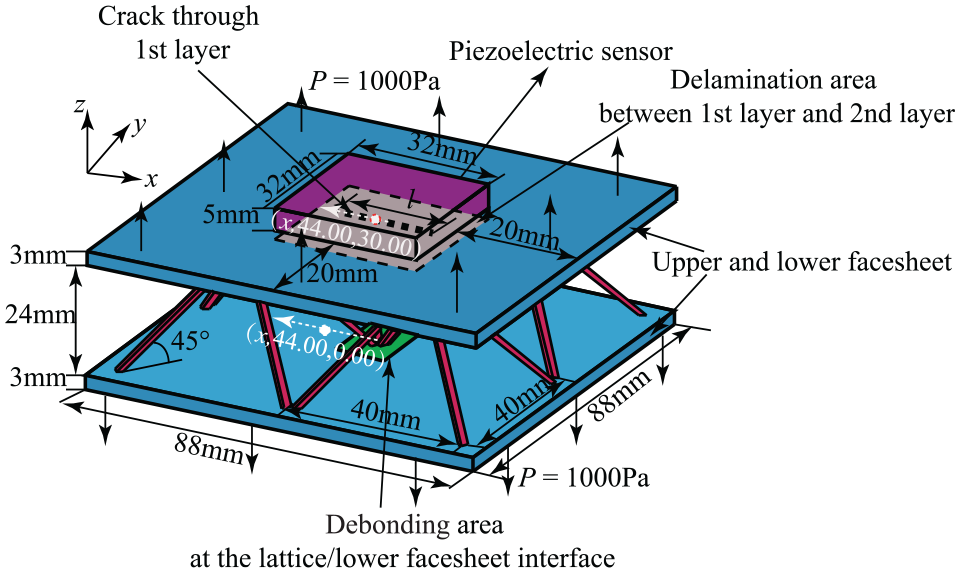
Composite sandwich structure with delamination, crack and debonding.
Maximum displacements and electric potential obtained by the XLW/SE and the 3D elasticity models for composite sandwich structure with delamination, crack and debonding.
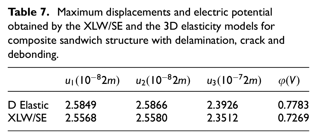
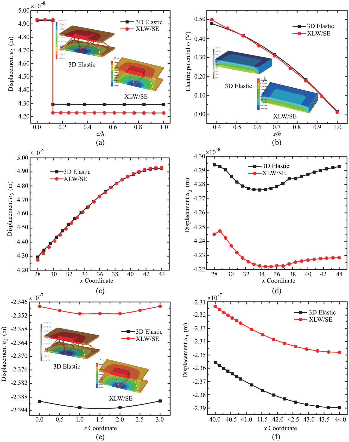
Distribution of displacements and electric potential of composite sandwich structure with multiple damage. (a) Displacement
Multiple damages will inevitably occur in the application process of composite sandwich structure. It is of great significance to research the coexistence of multiple damages. As shown in Table 7 and Figure 16, the proposed method can be used to analyze the composite lattice structures with multiple damages. The results of the proposed method are in good agreement with those of the 3D elasticity model. The more complex coupling analysis problem of composite sandwich structure and piezoelectric structure has been verified.
Next, the composite sandwich structure with multiple damages when the facesheets are anisotropic material property is studied. Geometric dimensions, damage locations and loads are consistent with Figure 15. The material properties of the facesheets are:
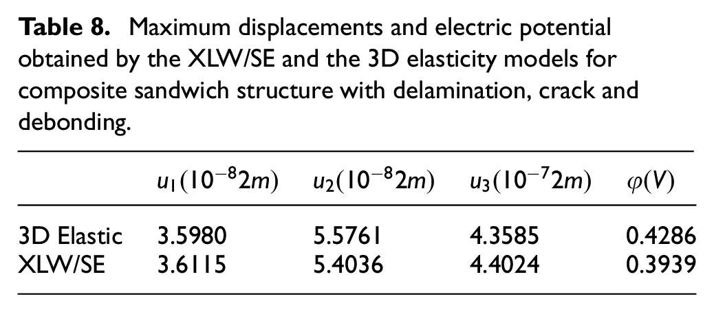
Maximum displacements and electric potential obtained by the XLW/SE and the 3D elasticity models for composite sandwich structure with delamination, crack and debonding.
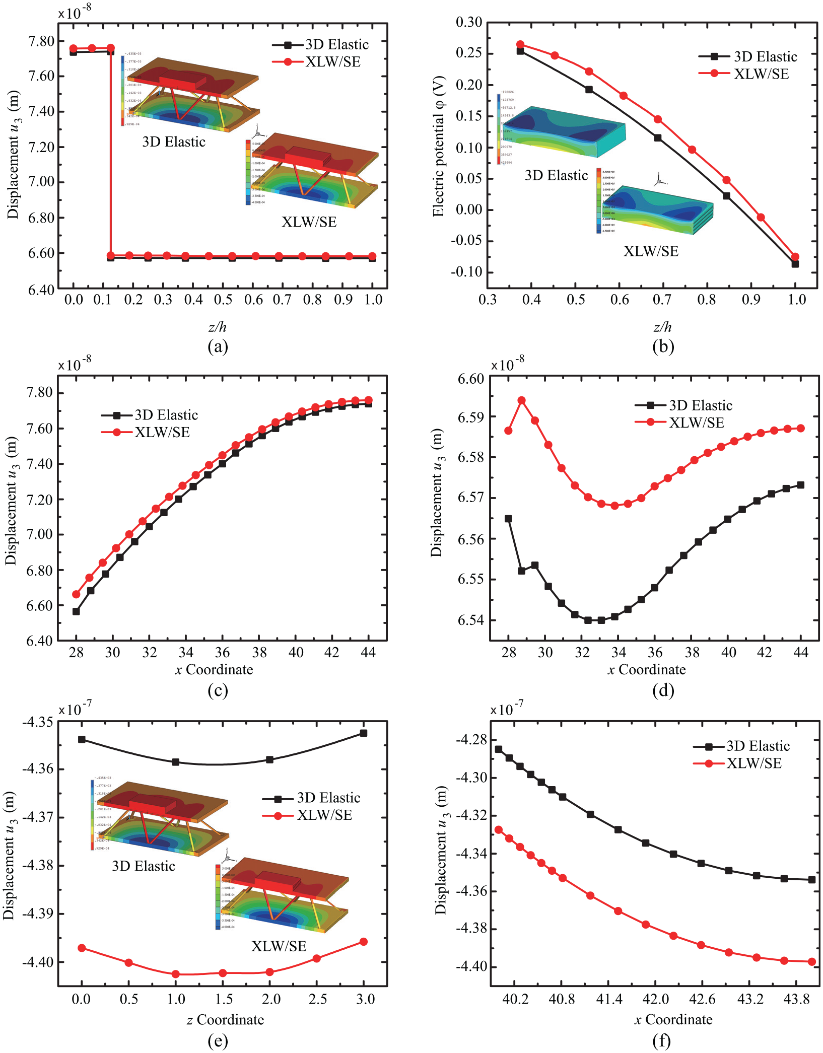
Distribution of displacements and electric potential of composite sandwich structure with multiple damage. (a) Displacement
The numerical comparison (Table 8) shows that the proposed method is in good agreement with the 3D elasticity model. By comparing Figures 16 and 17, it can be seen that the anisotropic material properties of the facesheet have obvious influence on distribution of the displacement
4. Conclusion
A XLW/SE method is established for the static response analysis of composite sandwich plates with piezoelectric sensor. The governing equation of piezoelectric sensor and facesheets is simulated based on the XLWM. The lattice is discretized based on the 3D solid element method. The final governing equation of composite lattice plates is assembled by using compatibility conditions and internal force equilibrium conditions. The XLW/SE method combines the advantages of XLWM and 3D solid elements. For the thick and thin plates, the modeling capabilities of XLWM are essentially the same as the conventional 3D displacement finite element method. But it can deal with a variety of damage problems in facesheets and piezoelectric patch. Compared with 3D solid element methods, the computational cost can be saved due to the 2D type data. The proposed XLW/SE method can accurately reflect the electric potential changes of piezoelectric sensor resulted from the damage. Numerical examples are carried out for isotropic composites lattice structures. Multiple types of damage are considered. The results of the proposed method are in good agreement with those of the 3D elasticity model developed in the commercial finite element software.
Footnotes
Appendix
Submatrixes of the stiffness matrix of piezoelectric senor are given by
Declaration of conflicting interests
The authors declared no potential conflicts of interest with respect to the research, authorship, and/or publication of this article.
Funding
The authors disclosed receipt of the following financial support for the research, authorship, and/or publication of this article: This work was supported by the Natural Science Foundations of China (12072364), Fundamental Research Funds for the Central Universities (3122019086)