
Abstract
This paper presents a magnetically coupling bending-torsion piezoelectric energy harvester based on vortex-induced vibration from low-speed wind. The theoretical model of the energy harvester was formulated and validated by wind tunnel experiments. Numerical and experimental results showed that the power output and bandwidth of the proposed harvester are improved about 180% and 230% respectively compared with the nonmagnetic coupling harvester. Furthermore, the effects of cylinder, piezoelectric layer, load resistance, and magnetic nonlinear parameters on the harvester were investigated based on the distributed parameter model. The results showed that the length of cylinder hardly affect output power, but the diameter of cylinder presented complicated influences. The width of piezoelectric beam was negatively correlated with the torsion angle. With increasing the length of piezoelectric layer, an optimal wind velocity and load resistance can be obtained for the maximum output power. With decreasing of the distance between two magnets, the resonant bandwidth, the optimal power output, and torsion angle can be enhanced, respectively. Besides, the magnetic potential energy increased owing to the magnetically coupling, which led to the improvement of onset speed for the energy harvester. This study provides a guideline on improving the performance of bending-torsion vibration piezoelectric energy harvester.
1. Introduction
With rapid development of portable electronic devices and micro-electromechanical systems, energy harvesting plays an important role in application for electricity supply (Fan et al., 2019a; Lai et al., 2019; Maamer et al., 2019; Zuo et al., 2020). Energy utilization has attracted widespread attention worldwide due to the diminishing of the non-renewable resources (Abdelkareem et al., 2018; Van Toan et al., 2019; Zhu et al., 2019). Traditionally, batteries have been chosen as the primary energy source for powering such devices. However, due to the chemical pollution of batteries and the characteristics of unsustainable power supply, the disadvantages of batteries are becoming more and more serious (Fan et al., 2019b; Fu and Yeatman, 2019; Fu et al., 2019). At the same time, energy harvesting from the ambient environment has been confirmed a promising technology that converting sustainable energy into electricity (Cao et al., 2021a, 2021b; Sun et al., 2019). Owing to the significant advantages of environmental protection, pollution-free, wide distribution, etc., wind energy is considered to the most widely used natural resource (Silva et al., 2020; Song et al., 2021; Vita et al., 2020; Wang et al., 2020a).
In principle, the piezoelectric effect (Fang et al., 2020; Li et al., 2019; Xie et al., 2020; Zhou and Zuo, 2018) and electromagnetic induction (Fang et al., 2021; Iqbal and Khan, 2018; Zhang et al., 2019) have been applied for transducing the wind energy into usable electric energy. Electromagnetic induction energy harvesters are mainly applied in large-scale power generation. The small-scale electromagnetic-based energy harvesters have electromagnetic interference to power supply systems, thus limiting their application. In contrast, piezoelectric ceramics are widely applied in high-frequency small deformation scenes because of their effective piezoelectric coefficient. It is worth noting that wind energy is abundant in nature, and researchers have developed numerous efficient piezoelectric energy harvesters (PEHs) with vortex-induced vibration (VIV) (Hu et al., 2018; Wang et al., 2021), galloping (Dash et al., 2020; Sun and Seok, 2021; Tan et al., 2021; Zhou et al., 2019), flutter (Eugeni et al., 2020; McCarthy et al., 2014), and wake-induced vibration (Xie et al., 2012; Zhao et al., 2021). The coupling between the airflow and bluff body produces unstable aerodynamic lift, which activates the deformation of the piezoelectric beam. The VIV piezoelectric energy harvester can work efficiently due to the vortex shedding frequency nearby the natural frequency of the system. Therefore, the optimal power output can be obtained by designing the structure of energy harvesting system for matching between the natural frequency of the VIV energy harvester and the frequency of vortex shedding. In recent years, a large number of scholars have reported the design and analysis of wind-induced piezoelectric harvester. Dai et al. (2014) modeled and experimented the performance of piezoelectric energy harvester based on vortex-induced vibration. The factors affecting the efficiency of energy harvesting were analyzed separately by using the distributed parameter method. On this basis, Lai et al. (2021) proposed a novel hybrid piezo-dielectric wind energy harvester to capture the vortex-induced vibration from low-speed wind. For improving the performance of power generation, Wang et al. (2019a, 2019b, 2019c, 2020c) investigated the output characteristic of Y-shaped attachments on the bluff body of spindle and butterfly-like cross-sections, triangle section. By changing the shape of the cross-section of the tip bluff body, the fluid motion conversation from vortex-induced vibration to galloping can be realized. At the same time, the energy harvest efficiency was significantly improved comparing to narrow-band vortex-induced vibration. What’s more, Wang et al. (2020b) introduced nonlinear magnetic force to realize broadband tristable and enhance the performance of energy harvester.
On the basis of traditional bending mode, a few researchers pay attention to utilize torsion vibration or bending-torsion coupling vibration for piezoelectric energy harvesting. From previous reports, Abdelkefi et al. (2011) proposed and modeled an asymmetric piezoelectric beam coupling bending-torsion vibration at the base excitation. The results showed that the asymmetric and the location of two mass could influence the output of the energy harvester. Shan et al. (2017) studied a piezoelectric energy harvester with a cylinder undergoing bending-torsion vibration in low-speed water. Compared with only undergoing bending, the harvester with bending-torsion vibration produced 1.99 times output power. Jia et al. (2020) presented a novel asymmetric vortex-induced piezoelectric harvester for capturing wind energy and found that the natural frequency and optimal wind velocity dropped as the eccentric distance of cylinder increased, furthermore, there existed an optimal eccentric distance cylinder for maximum output power.
In this work, a novel magnetically coupling bending-torsion piezoelectric energy harvester (MCBT-PEH) is proposed to scavenge vortex-induced vibration energy from low-speed wind. The structure and magnetically coupling bending-torsion energy harvesting mechanism are introduced in section 2. Based on Euler-Bernoulli beam theory, the distributed-parameter model of the harvester is established in section 3. In section 4, wind tunnel experiments are designed and conducted to validate the analytical model. The geometric parameters that affect the performance of the energy harvesting system are analyzed by simulation results. At last, the comprehensive conclusions are drawn in section 5.
2. Design and prototype of the harvester
As shown in Figure 1, the MCBT-PEH is comprised of an eccentric cylinder attached at the end of a piezoelectric beam. The piezoelectric sheet is adhered to the substrate layer by the epoxy adhesive. A pair of magnets are equipped to introduce the nonlinear magnetic force. The moving magnet is inserted at the bottom of bluff body, and the other fixed magnet is placed along the vertical. In this study, the material of bluff body, substrate layer, piezoelectric layer is made of foamed plastic, pure aluminum, and PZT-5H, respectively. Owing to the eccentric distance between the cylindrical center and the piezoelectric beam axis, the aerodynamic lift force applied to the cylindrical center under the excitation of incoming wind. Therefore, the bending and torsion vibration of the energy harvester can be induced simultaneously.
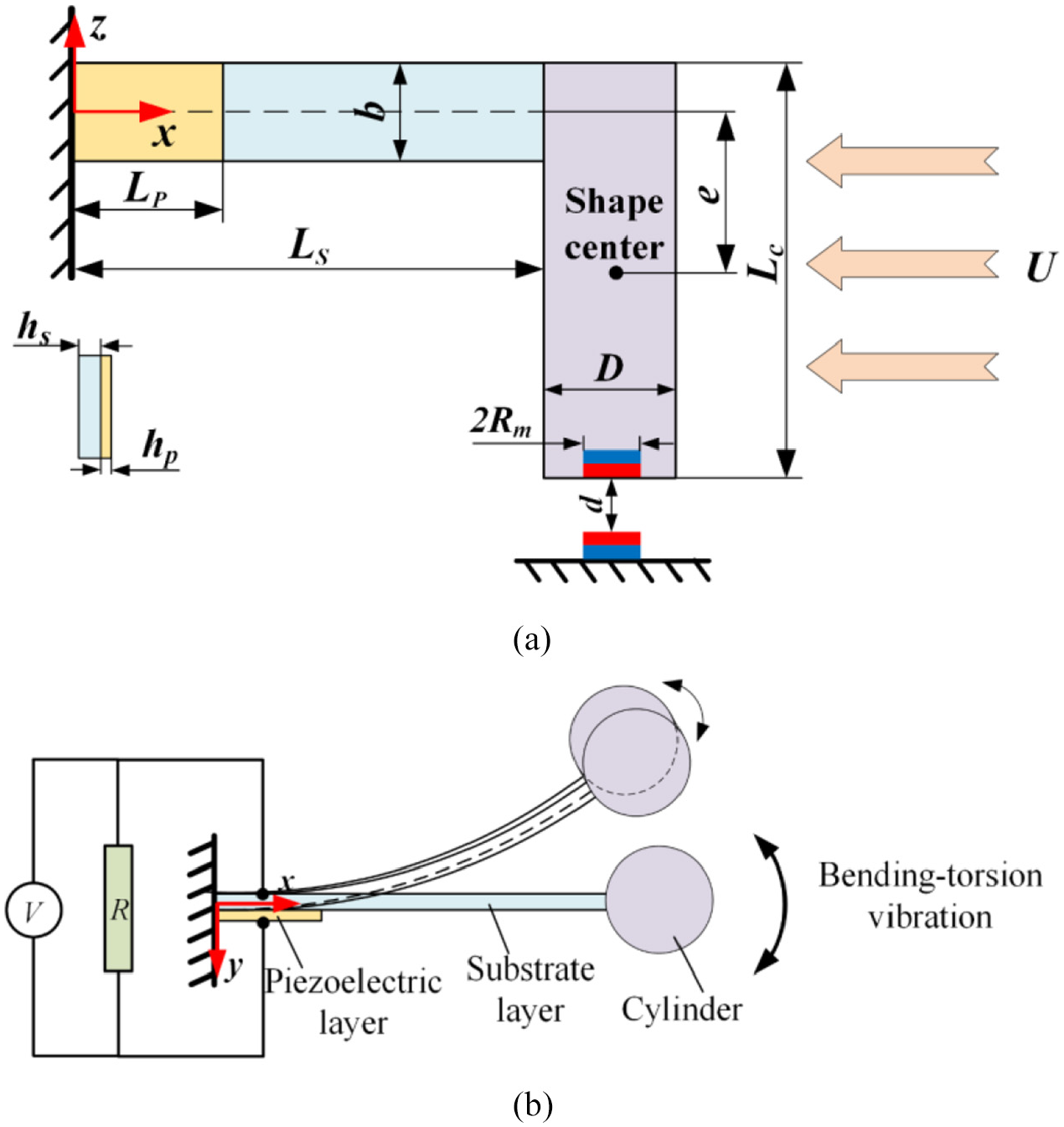
Schematic and composition of the system: (a) front view of the system and (b) top view of the system.
As displayed in Figure 1(a), the length of piezoelectric layer and substrate layer are Lp and Ls respectively. It is noticeable that the piezoelectric layer and substrate layer have the same width as b in this study. hp and hs are the thickness of piezoelectric layer and substrate layer, respectively. The diameter and length of cylinder are D and Lc. The eccentricity between the piezoelectric beam and the shape center of cylinder is e. Rm and hm are the radius and thickness of magnets, the distance of two magnets d is adjustable. U is the speed of incoming wind. Figure 1(b) shows the corresponding equivalent electric circuit and bending-torsion vibration mode, therein, V and R are individually the transient voltage and the external load resistance.
3. Modeling of energy harvest system
In this subsection, the distributed parameter model of the system is established according to Hamilton Principle and Lagrange Equation. To conduct the mathematic modeling and analysis of the energy harvesting system, the assumptions are as following:
(1) The piezoelectric is stuck on the substrate layer and the impact of adhesive glue is neglected.
(2) The piezoelectric beam satisfies the Euler-Bernoulli hypothesis.
(3) The moving magnet and fixed magnet are coaxial in the initial position.
To simplify the modeling expression, the following provisions are made:
(1) “
(2) “
(3) The script “p” and “s” are individually interpreted as the piezoelectric layer and substrate layer.
(4) w(x, t) and φ(x, t) are individually interpreted as the deformation and torsion of the piezoelectric beam with respect to coordinate x and time t.
In addition, the neutral layer is not at the geometric center because of the different thickness of piezoelectric and substrate layer, thus the position of the neutral layer of piezoelectric beam should be determined. It can be obtained according to the principle of stiffness equivalence and given by
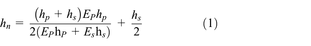
where Es and Ep are the Young modulus of substrate layer and piezoelectric layer, respectively. As depicted in Figure 2, the coordinate of ha, hb, and hc can be defined concerning hn and expressed as ha = −hn, hb = hs−hn, hc = hs+hp−hn.
Schematic diagram of relationship between ha, hb, and hc with neutral axis.
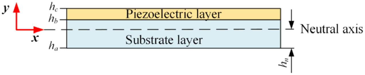
Due to the vibration mode change, compound vibration of bending-torsion rather than simply bending, two different coordinate systems are needed to describe the vibration of piezoelectric beam. As sketched in Figure 3, the fixed coordinate system o-xyz fixed to the clamped side of piezoelectric beam for expressing the bending motion. Meanwhile, the reference coordinate system o1-ξζη at the free end of piezoelectric beam for expressing the torsion motion.
Diagram of piezoelectric cantilever bending-torsion deformation.
In order to obtain the distributed-parameter model and governing equation of energy harvesting system, we first calculated the system energy including the total kinetic energy, the total potential energy, and the virtual work. The total kinetic of energy harvesting system T is the sum of the kinetic energy of piezoelectric beam Tb, attached cylinder and added kinetic energy of fluid Tc, which are given by
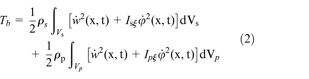
where, ρs and ρp are respectively the density of substrate layer and piezoelectric layer, Vs and Vp are respectively the volume of substrate layer and piezoelectric layer, Isξ and Ipξ are respectively the rotational inertia of the substrate and the piezoelectric layer with respect to the ξ axis.
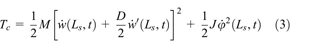
M and J are individually the total mass and the moment of inertia with respect to the ξ axis, which can be given by

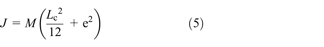
where, Mc and Mm are the mass of cylinder and moving magnet, Mf is fluid-added mass, which can be expressed by Mf = CMπ(D/2)2Lcρf,ρf is the density of air flow, CM = 1 (Facchinetti et al., 2004).
The total potential energy U including the piezoelectric beam bending-torsion potential energy Ub, the electric potential energy of piezoelectric layer Ue, the gravitational potential energy of cylinder Ug, and the magnetic-induced nonlinear potential energy Umag, which are expressed by
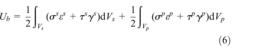
where the bending-torsion strain (i.e. ε and γ) and stress (i.e. σ and τ) of piezoelectric beam are given as follows


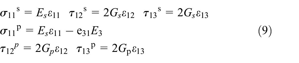
the subscript number of the letter are arbitrary constants except for e31, Gs and Gp are the Shear modulus of the substrate layer and the piezoelectric layer respectively. e31 is the piezoelectric strain constant. E3 is the electric field intensity expressed by E3 = V(t)/hp, and V(t) is the output voltage of the piezoelectric layer.
The electric potential energy of piezoelectric layer Ue can be given by
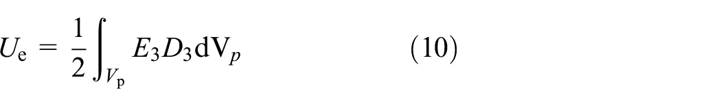
where D3 is the electric displacement vector of piezoelectric layer can be calculated by

ε33 is the piezoelectric permittivity under constant stress.
The gravitational potential energy Ug is caused by the deviation of the cylinder’s center from the equilibrium position due to bending and torsion vibration, which can be given by

Umag is the magnetic-induced nonlinear potential energy (Naseer et al., 2017), which can be given by
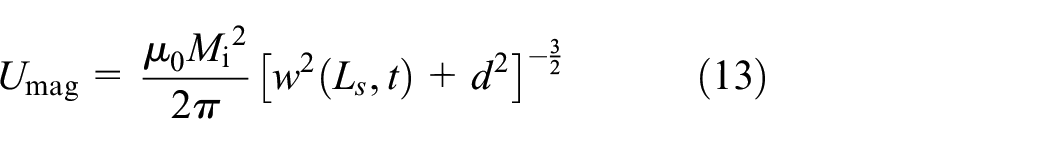
where μ0 is the vacuum permeability, Mi is the magnetization intensity which can be expressed by Mi = Br/μ0*Vm, where Br and Vm are the residual magnetic induction and the volume of magnet, respectively.
The virtual work δW consists of the virtual work of external resistance δWR, mechanical damping δWc, fluid drag force δWf and lift force δWF, which can be given by

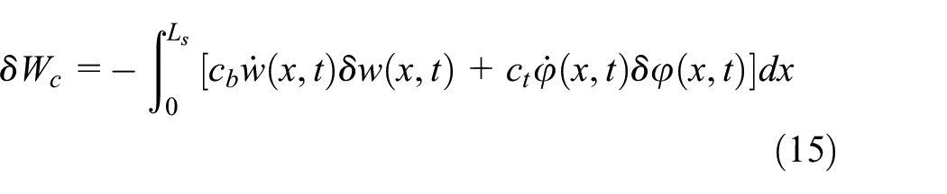
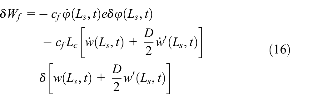
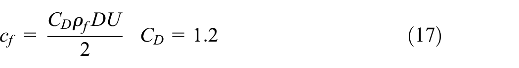
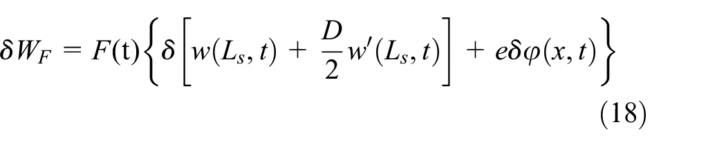
where QR is the amount of charge between the electrodes of the piezoelectric layer. cb ct, and cf are respectively the bending damping coefficient, torsional damping coefficient of the piezoelectric beam, and the fluid drag force per unit length. CD is the fluid drag force coefficient. F(t) is vortex-induced lift force, which can be expressed by
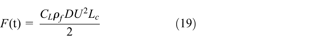
CL and CL0 are individually the vortex lift coefficient and reference lift coefficient on the unfixed cylinder undergoing vortex shedding. In order to describe the vortex shedding in the near wake of the cylinder, q(t) = 2CL/CL0 is introduced by Van der Pol equation and expressed by (Facchinetti et al., 2004)
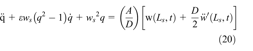
where ws is vortex shedding frequency, and given by ws = 2πStU/D. ε and A are the tunable parameters and given by 0.35, 12, respectively. St is the Strouhal number, which is confirmed by Reynolds number and the shape of cross-section. The value of S t is given by 0.2 in this study.
To obtain the dynamic response of the MCBT-PEH, a reduced-order model is confirmed by using the Galerkin procedure to discretize the above energy equations. The bending and torsion vibration displacement of piezoelectric beam are individually given by
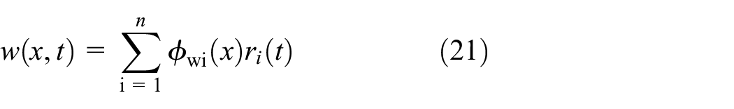
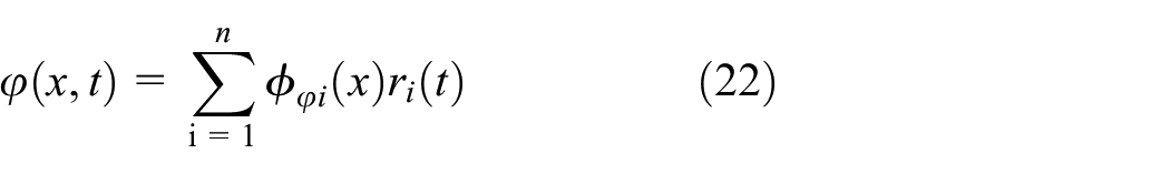
Where ϕwi(x) and ϕφi(x) are the bending mode function and torsion mode function, ri(t) is the mode coordinate.
Due to the response of energy harvester caused by wind-induced vibration is low frequency, the first-order mode is dominant and the other higher-order modes have little effects. Consequently, equations (21) and (22) can be rewritten by


and r1(t) = Acosωt + Bsinωt, ω is the natural frequency of system, A and B are arbitrary constants.
It is worth noting that the piezoelectric layer is not fully covered the substrate layer, as a result, the bending and torsion mode function should be separated into two parts, which can respectively be given by
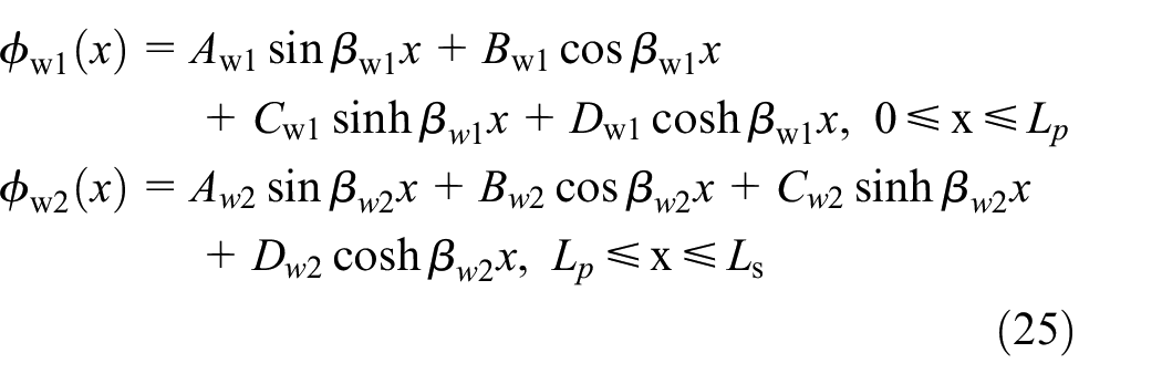
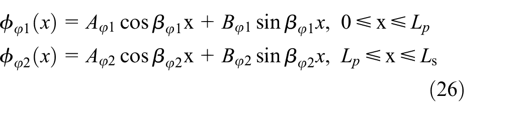
where Awi, Bwi, Cwi, Dwi, Aφi, and Bφi (i = 1, 2) are arbitrary constants, which can be determined by boundary conditions. The parameters βwi are related to βφi and given by
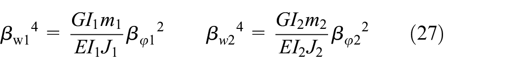
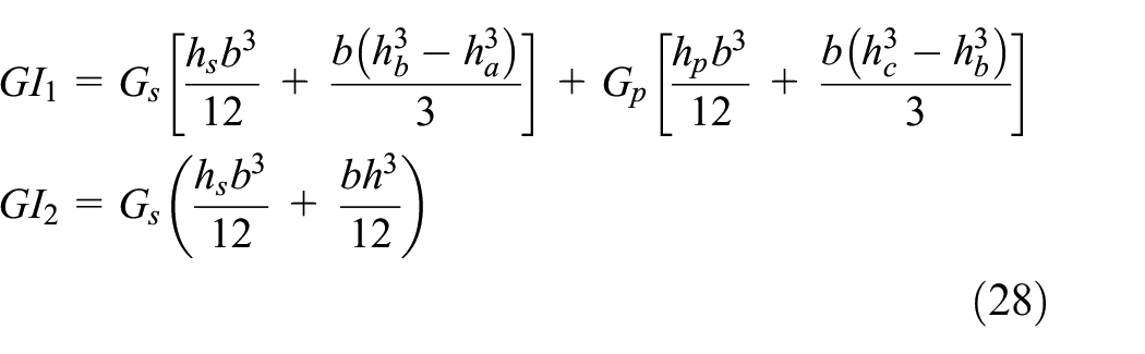
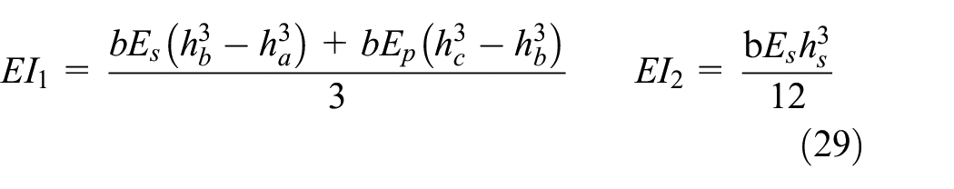
where GI1 and GI2 are the torsion stiffness around ξ axis, EI1 and EI2 are the bending stiffness along x axis, J1 and J2 are the moments of inertia around ξ axis, m1 and m2 are the mass per unit length of piezoelectric beam where 0 ≤ x ≤ Lp and Lp ≤ x ≤ Ls, respectively. The above parameters are expressed by

To confirm the bending mode function and torsion mode function, the boundary conditions of energy harvest at x = 0 and x = Ls are expressed by

where
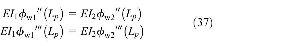
At the end of piezoelectric layer along x-axis, that is, x = Lp, the boundary conditions can be determined as


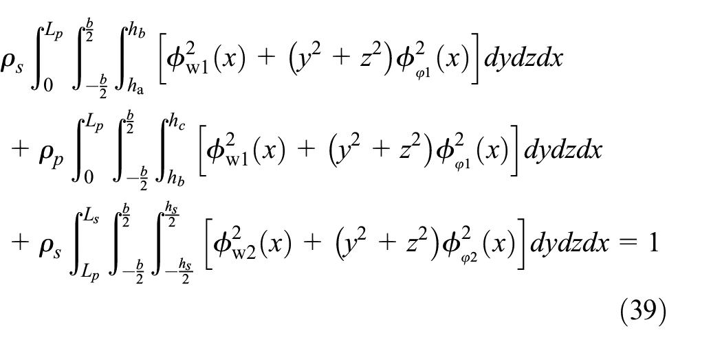
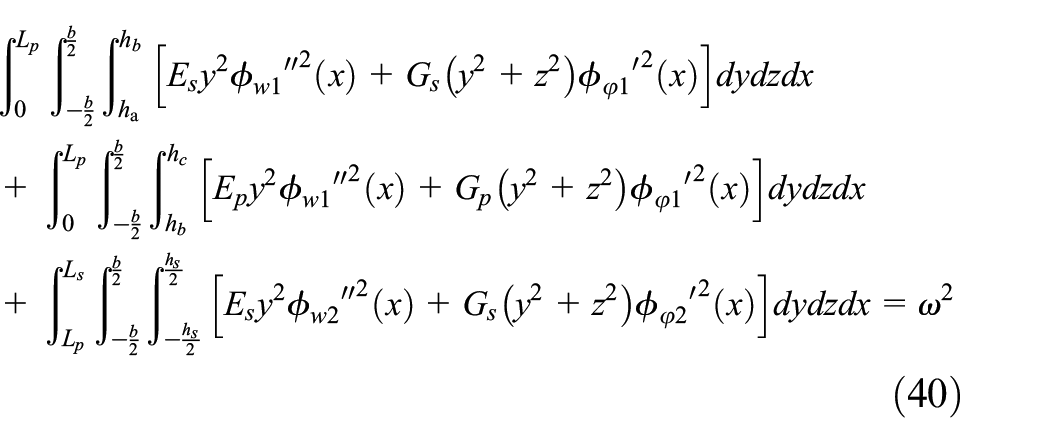
Based on the orthogonality conditions of normalized mode shapes, the mass matrix and stiffness matrix of the system can be confirmed and expressed as
To confirm the fluid-solid-electric coupling governing equation of piezoelectric energy harvest system, Submitting the equations (23), (24) to (2)–(20) and introducing Lagrange term L, which can be expressed by

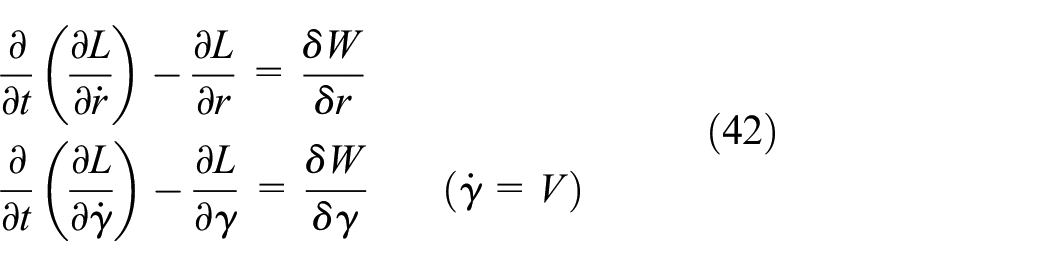
Furthermore, the Lagrangian method is given by
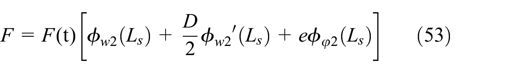
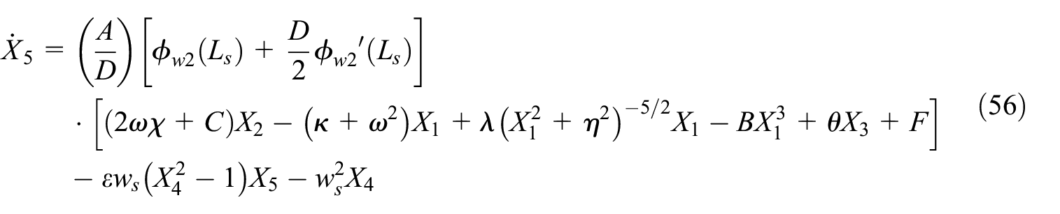
Finally, the reduced-order modeling of the MCBT-PEH is obtained as follows
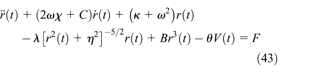
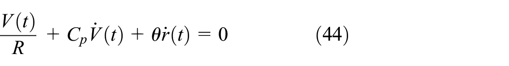
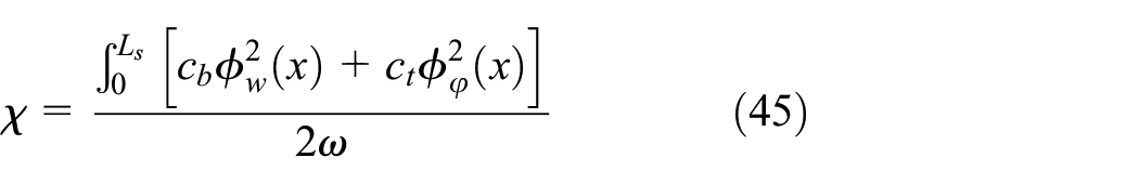
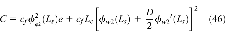
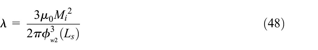
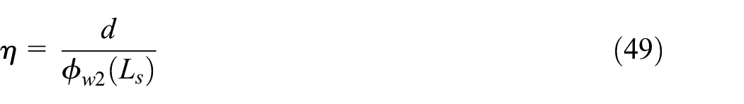
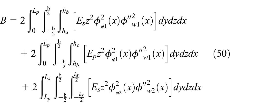
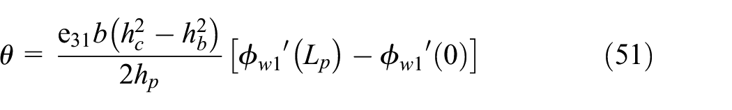
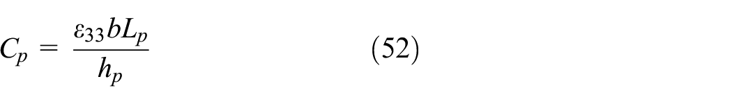
where χ is the mechanical damping ratio of energy harvest system, which can be measured by free vibration test. B is the coefficient of coupling bending and torsion vibration. θ and Cp are the electromechanical coefficient of system and the equivalent capacity of piezoelectric layer, respectively. The parameters χ, C, κ, λ, η, B, θ, Cp, F are respectively given by

In order to solve the reduced-order mathematical model of system, the state variable is introduced and given by
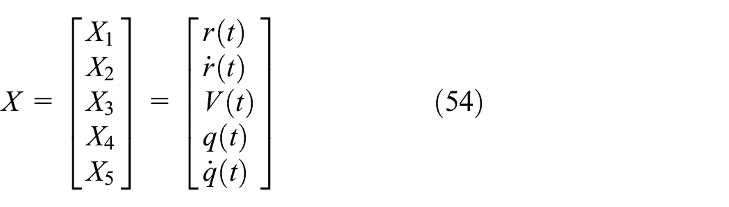
The state-space equation of the energy harvest system is established and expressed as
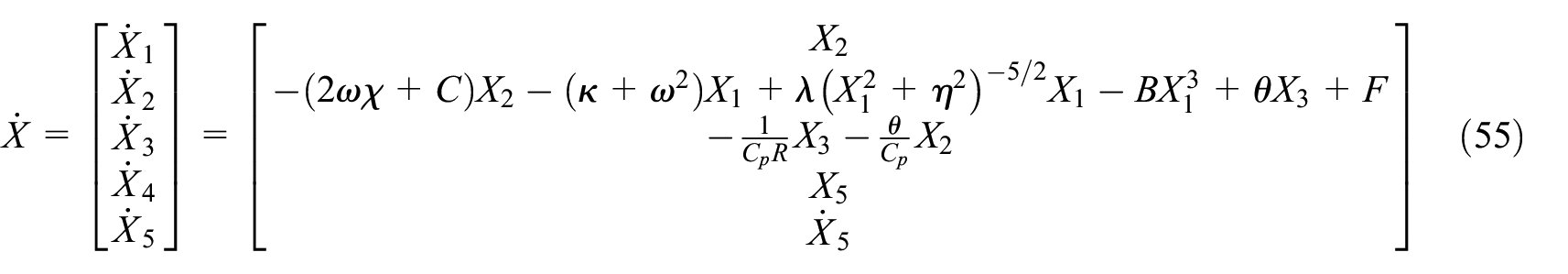
where
The output power is an important index to evaluate the performance of energy harvester, which can be expressed as P = V2rms/R, Vrms is root mean square voltage and R is external load resistance.
4. Experimental verification and results discussion
4.1. Experimental verification
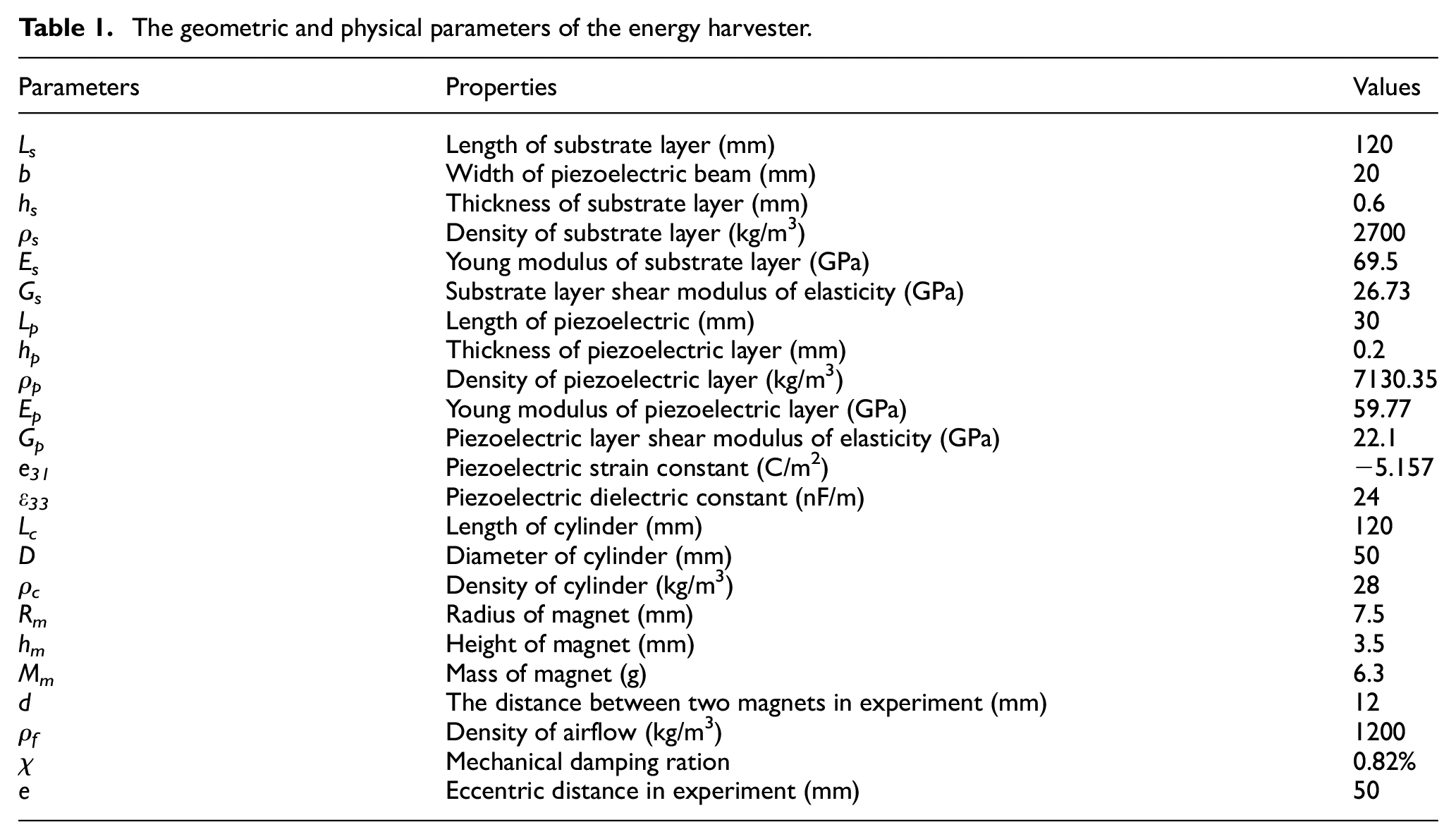
Figure 4(a) illustrates the wind tunnel test system. The test system is mainly composed of a centrifugal blower, frequency converter, data acquiring, and processing device. Wherein, frequency converter is a controller, which can adjust the centrifugal blower rotation speed to obtain different wind speeds. And the wind speed is measured by an anemometer. In addition, the data acquiring and process device including a NI acquisition card and a computer, which can record and dispose the output voltage in real-time. To stabilize the airflow, the honeycomb is installed in the wind tunnel. Figure 4(b) shows the piezoelectric energy harvesters with bending-torsion (BT-PEH) and magnetically coupling bending-torsion (MCBT-PEH), respectively. Table 1 lists the geometric and physical parameters of the energy harvester in detail.
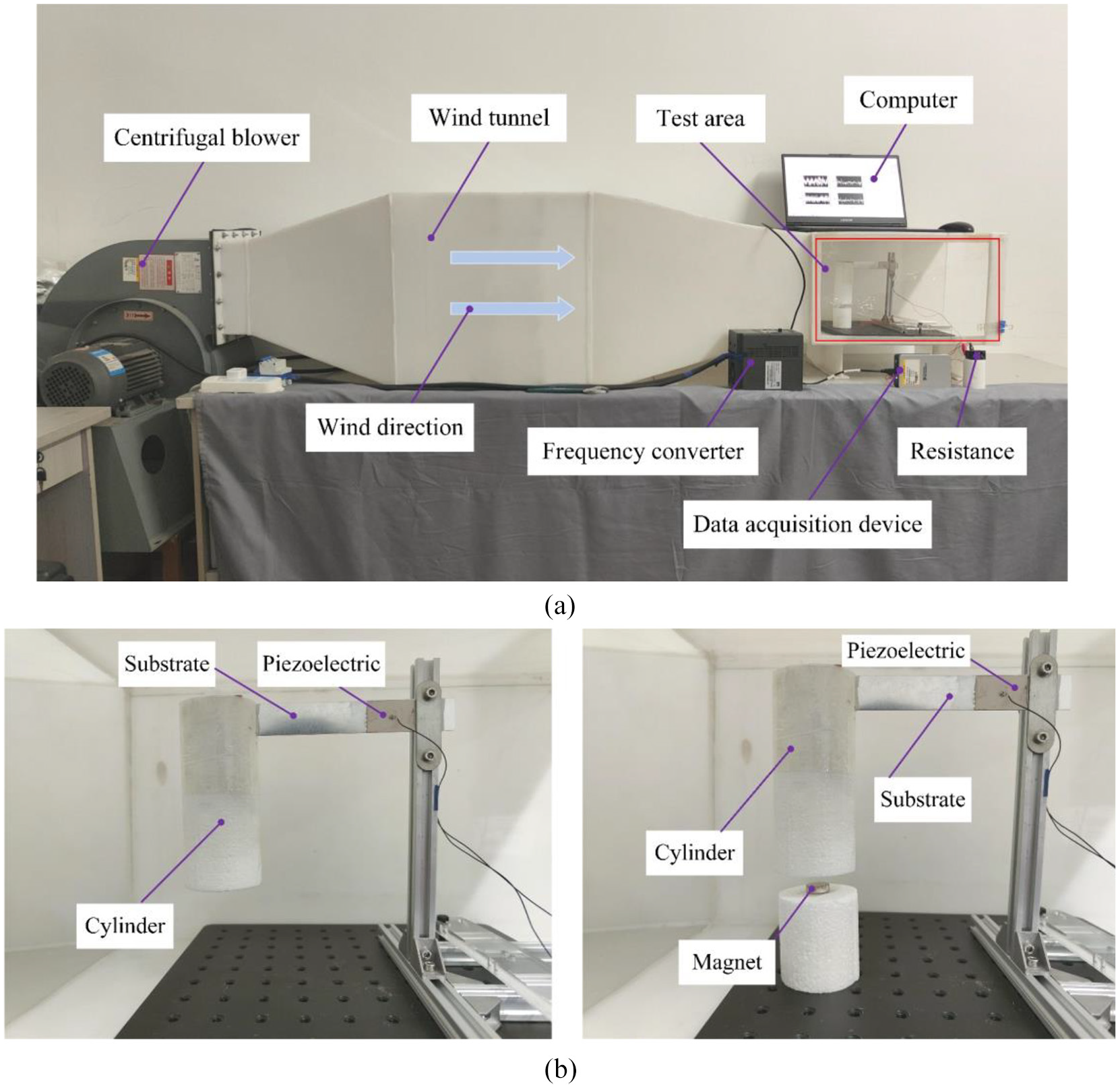
Experimental test system and devices: (a) experimental platform and (b) prototype of the BT-PEH and MCBT-PEH.
The geometric and physical parameters of the energy harvester.
The mechanical damping ration χ was confirmed by free vibration attenuation method, specifically, calculation based on voltage attenuation curve. The mechanical damping ration formula can be expressed as χ = ln(A1/An + 1)/(2πn), A1 and An + 1 are the first voltage amplitude and n + 1 voltage amplitude, respectively.
To determine the optimal value of the external load resistance, the numerical and experimental results for BT-PEH at the wind speed of 2 m/s are shown in Figure 5(a). It can be found that the piezoelectric energy harvester could achieve 308.3 μW of theoretical output and 297.2 μW of experimental output. Figure 5(b) shows a comparison between theoretical and experimental results of the MCBT-PEH at the wind speed of 4 m/s with different load resistance. From Figure 5(a) and (b), it can be concluded that the optimal value of load resistance was 300 kΩ when the harvester absence of magnet, and 200 kΩ when coupling magnetic force. To further verify the accuracy of mathematical model, as shown in Figure 6, the output power of two kinds of energy harvesters with different wind speeds were obtained at their respective optimal load resistance. For the BT-PEH, in Figure 6(a), the maximum power was 313 μW at 2.05 m/s from the theoretical simulation, while 297.2 μW at 2 m/s in the experiment. It can be clearly seen in Figure 6(a) that there is a sharply decrease in the second half. The reason for this phenomenon is that the wake oscillator model is an empirical model, which does not fully simulate the fluid-solid coupling dynamics. For the MCBT-PEH, the maximum power was 590.8 μW from the theoretical simulation while 580.2 μW at 4 m/s in the experiment. It is seen that a good agreement was obtained between the theoretical and experimental results. It is worth noting that the output power exhibited the same trend of increasing at first and then decreasing as the wind speeded up continuously. The reason for this phenomenon should be that the vortex shedding frequency increased gradually until the natural frequency of the system with the increase of wind speed. The lift force of vortex shedding brought the system into resonance and improved power output. However, as the wind speed increased continuously, the frequency of vortex shedding decreased significantly, which lead to a decrease in power output. Additionally, it could be found from Figure 6 that the theoretical analysis and experiment results of output power with magnetic force were better than that without magnetic force. Meanwhile, the introduction of nonlinear magnetic force resulted in a higher and wider effective working bandwidth.
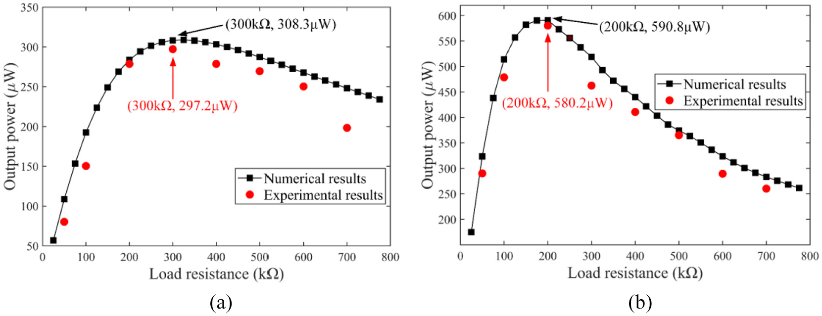
Comparison of theoretical and experimental results in output power at different load resistance: (a) BT-PEH and (b) MCBT-PEH.
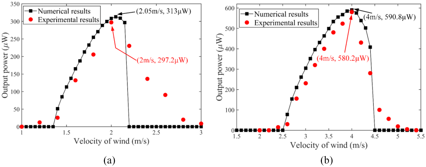
Comparison of theoretical and experimental results in output power at different wind speeds: (a) BT-PEH and (b) MCBT-PEH.
4.2. Simulation analysis of the MCBT-PEH
4.2.1. Effects of the bluff body
To further investigate the performance of the MCBT-PEH, the geometric parameter studies were executed, such as the physics size of cylinder, the width and length of piezoelectric layer, the effect of external load resistance and the distance between two magnets. Attentively, the control variable method was employed in the following discussion. Under the optimal load resistance of 200 kΩ, the output power and vibration displacement of the MCBT-PEH were studied with the cylindrical length of 100, 110, 120, 130 mm, respectively. It can be concluded in Figure 7 that the length of cylinder had little impact on the optimal output power, however, the resonance region shifted to the left as the length of the cylinder increased. The onset speed of flow decreased with the increase of cylindrical length and indicated that it was easier to convert flow energy into electricity through the piezoelectric effect. The reason for this phenomenon may be the complex coupling vortex shedding on the leeward side, which led to the positive correlation between the cylinder length and the vortex lift force.
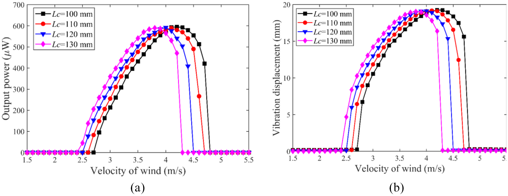
Performance comparison of the energy harvester with different cylindrical lengths versus wind speed: (a) output power and (b) vibration displacement.
Figure 8(a) illustrates the simulation results of output power versus the velocity of wind at four kinds of cylindrical diameters. It can figure out that the output power and vibration displacement also increased firstly and then decreased with improving wind speed. From the point of onset wind speed and cutoff wind speed, there were great differences between cylinders of different diameters. The theoretical analysis results illustrate that the width of resonance domain was gradually improving with the increase of wind speed. For example, the resonance domain was △1 = 4.3−2.5 = 1.8 at the diameter of 45 mm, and △4 = 4.8−2.7 = 2.1 at the diameter of 60 mm. Compared with the vibration displacement as shown in Figure 8(b), the variation of output power with wind speed was more complicated. The reason for this phenomenon should be that the diameter of cylinder had a relationship with the vortex shedding frequency as shown in ws = 2πStU/D and vortex-induced lift force in equation (19), which can be expressed the negative and positive correlations, respectively. At the same time, the vortex shedding frequency and vortex-induced lift force also had a corresponding relation in equation (20).
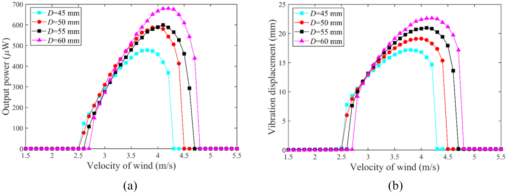
Performance comparison of the energy harvester with different cylindrical diameters versus wind speed: (a) output power and (b) vibration displacement.
4.2.2. Effects of piezoelectric beam
The fluid-induced energy harvester can capture the vibration energy from the piezoelectric cantilever beam. Hence, the size of piezoelectric layer, and load resistance should be investigated and analyzed in detail. Firstly, the changing law of the torsion angle of the piezoelectric beam with the width of 5, 10, 15, 20 mm were investigated, as shown in Figure 9. The simulation results indicated that different widths significantly influenced the torsion angle and the resonance domain. The torsion angle decreases as the width increases, which can be explained that the torsional stiffness GI is positively correlated with the width of the piezoelectric beam in equation (28).
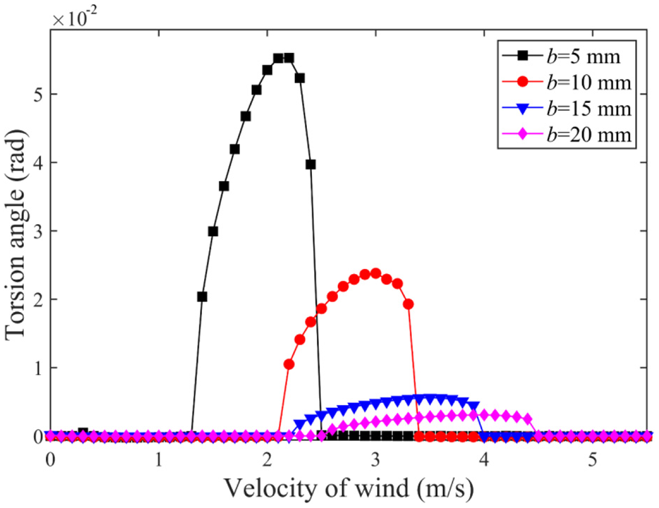
Performance comparison of the energy harvester with different piezoelectric beam widths versus wind speed.
Figure 10(a) illustrates the variation of output power with wind speed at different piezoelectric layer lengths. The optimal output with increasing of piezoelectric layer length and the corresponding optimal wind speed also slightly improved. In contrast, the highest vibration displacement decreased with increases of piezoelectric layer length, as shown in Figure 10(b). The reason was that increasing the piezoelectric layer length improved the area of power generation, while the stiffness of the system was also increased, which resulted in the improvement of power generation and vibration amplitude reduction respectively. From the resonance domain, the bandwidth of resonance domain hardly changed but the whole resonance domain shifted to the right as the length of piezoelectric layer increased. The piezoelectric ceramic has piezoresistive (i.e. the resistivity varies with the pressure applied), and the output power is maximum when the external resistance matches the internal. As shown in Figure 11(a), the results show that the optimal resistance existed in different lengths of piezoelectric layer with great differences. Specifically, the optimal resistance decreased but output power increased with the increasing of piezoelectric layer length. It can be concluded in Figure 11(b) that the optimal resistance was almost unchanged at the wind speed of 3.0, 3.5, 4.0, 4.2 m/s, respectively. According to the above analysis, the external resistance should be adjusted when changing the length of piezoelectric layer to obtain the optimal power.
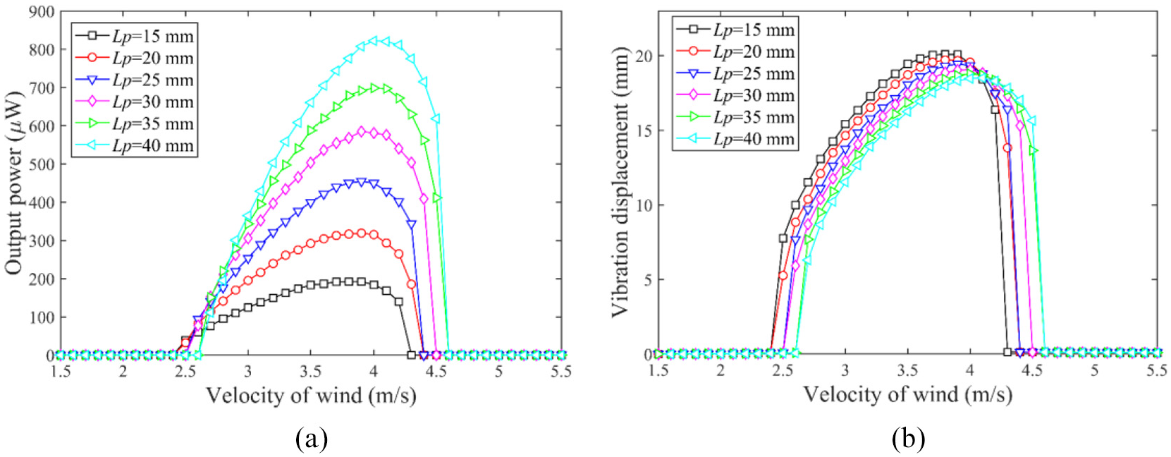
Performance comparison of the energy harvester with different piezoelectric layer lengths: (a) output power and (b) vibration displacement.
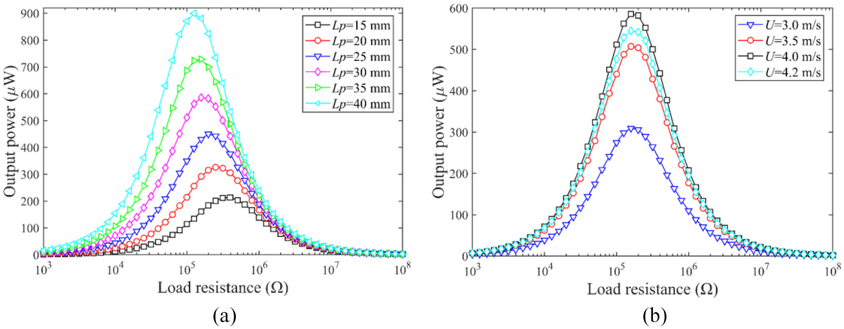
Output power of energy harvester versus load resistance: (a) lengths of piezoelectric layer and (b) wind speeds.
4.2.3. Effects of the nonlinear magnet force
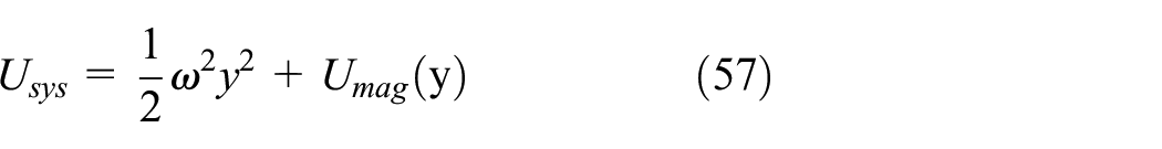
To explain the function of nonlinear magnetic force in the MCBT-PEH, Figure 12(a) presents the output power of the harvester corresponding to four different distances between the moving magnet and the fixed magnet. It can be seen that the resonance domain moved to left and the bandwidth of resonance decreased as the distance between two magnets getting further. Besides, the performance of energy scavenging was degraded with increasing the distance between two magnets. It can be concluded in Figure 12(b) that the torsion angle was negatively correlated with the distance between two magnets. The reason for this phenomenon was that when the cylinder moved to the limit position on both sides under the action of vortex-induced force, the magnet repulsion force decreased with increasing magnet distance, and resulted in the decreasing of the torsion angle amplitude. As shown in Figure 12(c), the curves illustrate the tendency of magnetic force along with vibration displacement at various d, which can be concluded that the magnetic force decreased with increasing d. According to previous reports, magnetic potential energy is an important indicator to judge the stability of the energy harvest system. The potential energy is given as follows (Zhou and Zuo, 2018)
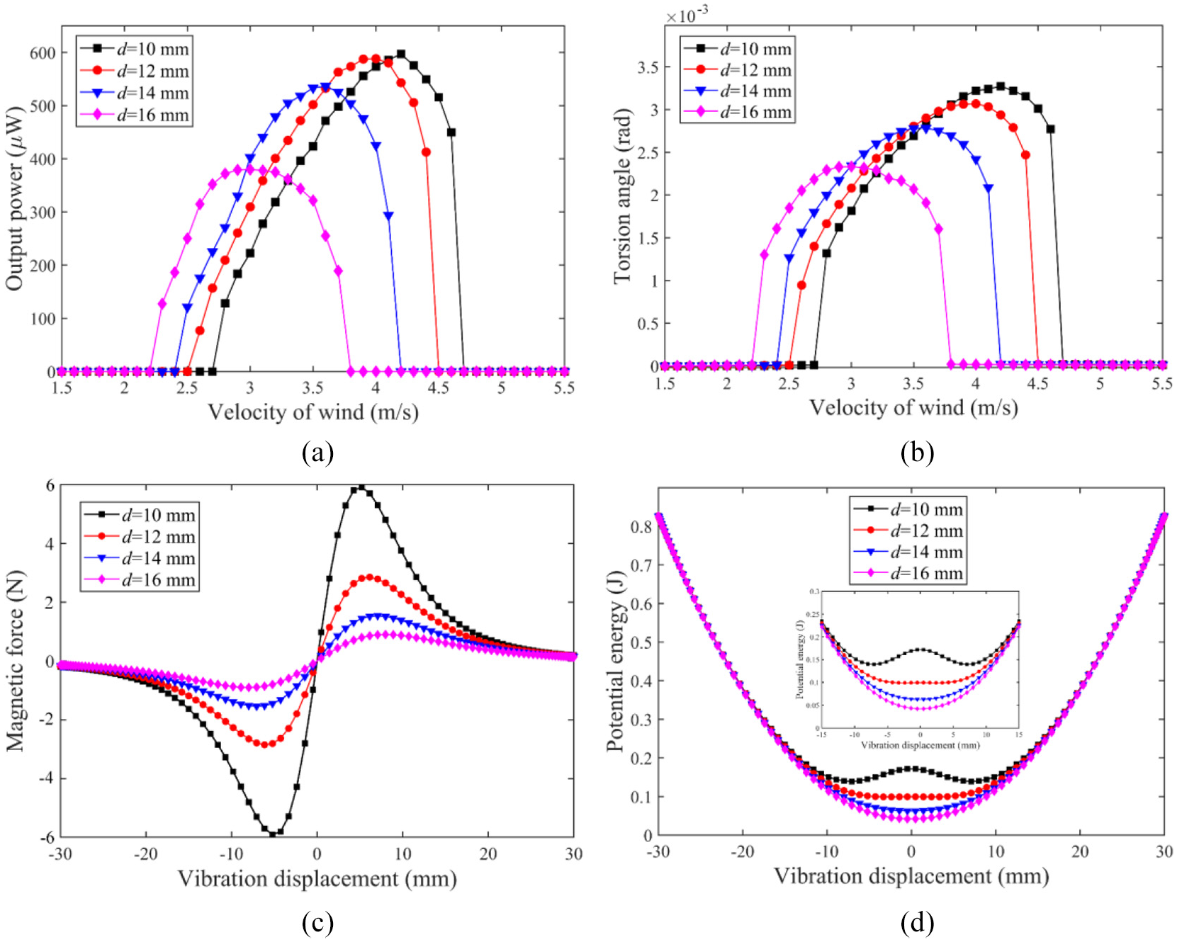
Output power (a) and torsion angle (b) of energy harvester with different d versus wind speed; magnetic force (c) and potential energy (d) of the system versus vibration displacement at different d.
where y is the vibration displacement. Figure 12(d) presents the relationship between the system potential energy and lateral displacement at the end of piezoelectric beam with different initial magnet center distances. The extremum of potential energy changed from single to double with decreasing of the distance between two magnets, which means the system realized the transition from monostable to bistable. It can be seen from the Figure that d = 12 mm was the boundary of monostable and bistable for the investigated distance. According to the relationship between d and the potential energy, it can be concluded that the onset wind speed increased to overcome the magnetic potential energy at the initial position, which had a good agreement with Figure 12(a).
5. Conclusion
This paper displays a magnetically coupling bending-torsion piezoelectric energy harvester, which consisted of an incompletely covered piezoelectric beam, an asymmetrically placed cylinder at the free end, and a pair of magnets. Based on the Euler-Bernoulli beam theory and Lagrange equation, a distributed parameter model of the system was established and the system energy including the total kinetic energy, the total potential energy and the virtual work are taken into account in the process of modeling. The dynamic response of system was obtained by the Galerkin procedure and the correctness of the model was verified by experiments. Compared with the BT-PEH, the MCBT-PEH had a good performance at high wind speed and 2.35 times wider resonance bandwidth. For the distributing parameter model, the parameters of cylinder, piezoelectric layer, load resistance, and magnets were simulated and analyzed respectively. The results showed that the cylindrical length had little effect on the power output, but left-shifted the resonance domain with increasing the length. And the influence of cylindrical diameter on energy capturing efficiency and resonance region was relatively ambiguous. With increasing the width of piezoelectric beam, the torsional stiffness improved and realized the transition from bending-torsion to bending-based motion state. It can be concluded that the output power increased with the length of the piezoelectric layer, but the vibration displacement decreased due to the variation of the piezoelectric beam stiffness. Additionally, the piezoelectric layer had an optimal matching external load resistance because of the piezoresistive effect. Finally, the effect of magnetic force on output power, torsion angle, and potential energy were investigated, which illustrated that the resonance domain and efficiency decreased with the increases of the distance between two magnets. In conclusion, this work provides a guideline on the optimization of the MCBT-PEH in practical applications.
Footnotes
Author contributions
Wentao Sui and Rujun Song proposed the prototype, designed the experiments, analyzed the datas; Huirong Zhang wrote the paper; Chongqiu Yang, Dan Zhang, and Xiaohui Yang assisted to do experiments and optimized the paper.
Declaration of conflicting interests
The authors declared no potential conflicts of interest with respect to the research, authorship, and/or publication of this article.
Funding
The authors disclosed receipt of the following financial support for the research, authorship, and/or publication of this article: This work was supported by the National Natural Science Foundation of China under Grant numbers 51705296 and 51905316.