
Abstract
Because of their electro-mechanical coupling property, Lead-Zirconate-Titanate (PZT) materials have been widely used for ultrasonic wave sensing and actuation in structural health monitoring applications. In this paper, a PZT rosette concept is proposed to conduct Lamb wave-based damage detection in panel-like structures by exploring its best directional sensing capability. First, a directivity study was conducted to investigate sensing of flexural Lamb wave propagation using a PZT fiber having d33 effects. Then, commercial off-the-shelf PZT fibers were polarized in-house in order to construct the PZT rosette configuration, in which three PZT fibers are oriented at 0°, 45°, 90°, respectively. Since Lamb wave responses are directly related to measured PZT fiber voltage signals, a simple interrogation scheme was developed to calculate principal strain direction in order to locate an acoustic source. Comprehensive tests were conducted to evaluate the performance of the proposed PZT rosette using an aluminum plate. It is shown that the PZT rosette is able to sense Lamb wave responses and accurately locate an acoustic source. We expect to further evaluate the PZT rosette performance when damages are introduced.
1. Introduction
Engineering structures, over the course of their service life, will experience various loading conditions and environmental effects. This will inevitably cause damage to the structure, which requires maintenance and inspection to ensure its safety and performance throughout its lifetime. Structural health monitoring (SHM) is a wide branch of study that is responsible for improving reliability and operational life of various structures. For the past few decades, nondestructive damage detection techniques using in-situ actuators/sensors have been widely explored. These methods have the advantage of being able to inspect the structures continuously. For solid bodies, wave propagation is a well-known phenomenon with an extensive history (Achenbach, 1984; Auld, 1990; Graff, 1975; Lamb, 1917; Nayfeh, 1995; Rose, 2014; Viktorov, 1967). Elastic waves and their propagation have been used for many years to study impact response problems and mechanical properties of various materials. The understanding of the interaction between a wave and a defect in an isotropic structure leads to the successful development of wave-based approaches in SHM applications. These wave-based methods are very attractive for damage detection in structures because they are very sensitive to small damage amounts and approximate extent of damage can be determined using less wave propagation information. Embedded smart actuators/sensors have been used by conducting Lamb wave transmission and reception, pulse-echo, pitch-catch, and phased array functions in order to achieve in-situ nondestructive evaluation for different structures (Giurgiutiu, 2007; Su and Ye, 2009). Acoustic Emission and ultrasonic inspection approaches are the most widely used techniques in industrial applications. The first technique, that is, AE, is passive and does not require any external signal excitation. Stress waves are structure-born and produced internally by defects. The second approach requires high-frequency external excitation. The maturity and proven damage detection applications are the major advantages of these techniques. The Acousto-Ultrasonic (AU) approach combines elements of Acoustic Emission and Ultrasonic inspection. Worlton (1956) is commonly cited as one of the first references to propose an acoustic ultrasonic type approach for damage detection in structures. Rose has presented a literature review of the most salient work with regard to AU research (Rose, 2002). Dalton et al. (2001) conducted studies of Lamb wave propagation through aircraft structures and noted that long range inspection is possible. Cawley and Alleyne (1996) discussed the different Lamb modes present in thin plates and their applicability toward damage detection. It is mentioned that dispersion, the change in the shape of the waveform as the wave propagates through the structure, is an important factor in choosing a wave mode for AU damage detection. Wilcox et al. (2001) extends Cawley’s thoughts about factors critical for AU inspection of structures.
Lead Zirconate Titanate (PZT) is a type of piezoelectric transducer that is extensively used in Lamb wave studies (Giurgiutiu et al., 2003; Grondel et al., 2002; Ihn and Chang, 2004; Kim and Sohn, 2007; Lemistre and Balageas, 2001; Lin and Yuan, 2001; Ostachowicz et al., 2009; Kessler et al., 2002). PZT transducers are advantageous as they have wide frequency responses, excellent mechanical strength, low power consumption and acoustic impedance. Multiple PZT sensors were used to form the phased array design in order to effectively conduct damage detection using guided Lamb wave responses in structures. Phased array processing of sensor array signals have been used in acoustic and antenna theory in order to improve signals arriving from a given direction (Ziomek, 1995). The wavenumber and frequency of the wave produce known phase shifts between the signals of each sensor, which are used for phased array processing. Such PZT phased array has been used for damage detection in isotropic structures using a linear array of sensors (Purekar, 2006; Purekar and Pines, 2001; Purekar et al., 2004). The use of sensor arrays as tools for damage detection in structures has shown wide applicability (Giurgiutiu and Bao, 2004; Kress et al., 2003; Ostachowicz et al., 2009; Purekar et al., 2004; Yoo et al., 2011). It must be emphasized that advanced signal processing algorithms are required in order to apply damage detection to such phased array systems.
Essentially, structural damage causes the unique wave scattering phenomena and mode conversion, and quantitative evaluation of damage can be achieved by examining wave signals (Su and Ye, 2009). Novel sensor concepts are needed to capture such wave scattering and locate acoustic sources due to actuation and reflection from damage in order to efficiently characterize structural damage extent and location. A piezoelectric rosette is an alternative solution to achieve such goals using Lamb wave propagation responses.
Kawiecki and Jesse (2002) first proposed a piezoelectric rosette concept, which is analogous to strain gage rosettes for 2D strain measurement. Four rosettes were placed on each corner of a panel to detect the wave responses. Three piezoelectric rectangular ceramic plates were used to form each rosette. Then, measured signals were fed to a neural network model to improve frequency response functions in order to extract damage-related information. Matt and Scalea (2007) constructed a rosette using three macro-fiber composite (MFC) piezoelectric patches (Smart Material Corp., Florida, USA), oriented 60° to each other, in order to locate acoustic source in a plate structure based on Lamb wave responses. Since piezoelectric d31 effects were assumed, the MFC patch was modeled as an orthotropic lamina under plane stress conditions, in which both longitudinal and transverse deformation must be included. In order to achieve high directivity to sense Lamb waves, a metal core piezoelectric fiber (MPF) rosette concept was proposed by Liu et al. (2010). The good directional properties of MPF were explored to determine the direction of propagation of Lamb waves by mounting three MPF sensors in a rosette configuration. The performance of the MPF rosettes for acoustic source location was demonstrated in an aluminum plate. These MPFs are specially designed and fabricated, and are not available commercially.
The MFC patch consists of piezoelectric fibers sandwiched between layers of adhesive, electrodes, and polyimide film in order to provide flexibility. The key element is the PZT fiber ranging from 125 to 800 microns in diameter. The d33 effect can be explored in each PZT fiber by introducing electrodes at both ends. Accordingly, we proposed a PZT fiber rosette concept by arranging three PZT fibers at 0°, 45°, and 90°, respectively. The goal was to explore best directivity for Lamb wave sensing. First, we carried out a directivity study to relate Lamb wave responses to PZT fiber voltage outputs. Then, apparatus were designed in order to polarize the PZT fibers. Note that such PZT fibers are commercially available but without pre-polarization. Subsequently, we designed and prototyped the proposed PZT fiber rosette system which consists of a cover layer, a PZT fiber housing layer with three slots, and a flexible circuit layer made by polyimide. Finally, comprehensive tests were conducted to evaluate the performance of PZT fiber rosettes in an aluminum plate structure, in which A0 Lamb waves under different frequencies were generated using a pair of circular PZT ceramic actuators. Lamb wave propagation responses were successfully captured by the PZT fiber rosettes. Moreover, a simple algorithm was employed to locate the acoustic source using collected PZT fiber voltage signal responses (Matt and Scalea, 2007), in which the principal strain direction was calculated in order to relate to the direction of Lamb wave propagation.
The paper is organized as follows. In section 2, a coupled electro-mechanical model is presented to relate Lamb wave responses to PZT fiber voltage outputs. Also, the directivity study is discussed to show directional sensing capability using PZT fibers. Section 3 discusses the PZT fiber polarization, and rosette design and fabrication. Section 4 shows the experimental setup. Results are included in section 5 and concluding remarks are shown in section 6.
2. PZT fiber sensing Lamb waves
In this section, first, we will discuss the PZT sensor model. Then, we will characterize the PZT fiber sensing capability when interacting with Lamb waves in an isotropic plate (Lamb, 1917; Viktorov, 1967). Finally, a simple algorithm is introduced to relate the direction of Lamb wave propagation to the principal strain direction in order to locate an acoustic source (Matt and Scalea, 2007).
2.1. PZT sensor model
Figure 1 shows the proposed PZT fiber rosette system when interacting with a Lamb wave. Note that only the top view is shown to illustrate the overall configuration for a PZT fiber rosette to sense Lamb wave propagation. The global coordinate system of a plate structure is denoted by the xy system. In addition, a local coordinate system (i.e. x’y’) is introduced to demonstrate the Lamb wave propagation direction, which is oriented at angle θ relative to the global coordinates. A numerical coordinate system is employed to describe a PZT fiber. The piezoelectric constitutive model is given below by applying one-dimensional assumption for PZT fiber (IEEE, 1988; Ikeda, 1990)

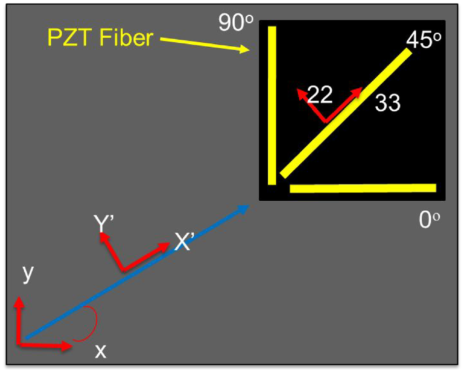
Schematic of a PZT fiber rosette for Lamb wave sensing.
Here,

By applying electrical boundary conditions of the PZT fiber sensor (Sirohi and Chopra, 2000), the total charge over the electrode area is zero, as shown below.
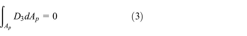
Here, Ap is the electrode area which is equal to the cross sectional area of PZT fiber. Finally, the collected voltage in PZT fiber sensor can be determined by
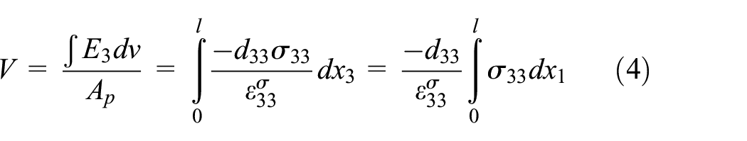
Here, l is the PZT fiber length. Note we assume that the fiber is perfectly boned on the surface of the plate. Also, we neglect the shear lag effect in above analysis.
The classical Lamb wave in-plane displacement, that is, A0 wave, can be expressed by (Lamb, 1917; Matt and Scalea, 2007; Viktorov, 1967).
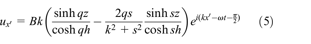
Here, B is an arbitrary coefficient for wave magnitude. h is the plate half thickness. k is the wavenumber and ω is the frequency. Two parameters, q and s, are defined by
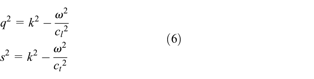
In these expressions, cl and ct are the longitudinal and shear/transverse modes velocities in the plate, respectively.
The characteristic equation for anti-symmetric Lamb wave (denoted by A0, A1, etc.) is

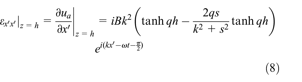
The frequency dependent wave number k can be determined from solving using a numerical solver (e.g. Matlab software). We can take the derivative with respect to x’ at the top surface of the plate (i.e. z = h) to obtain the strain (Matt and Scalea, 2007):
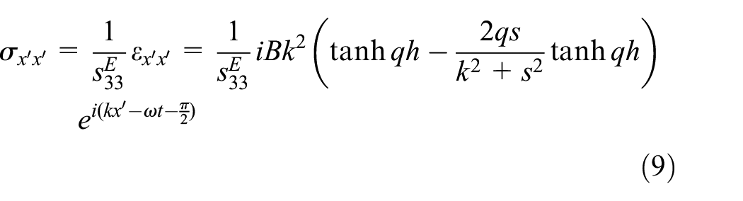
As aforementioned, since uniaxial strain and stress is assumed in PZT fiber, the stress is given by
Now, we calculate the collected voltage in PZT fiber as shown below.
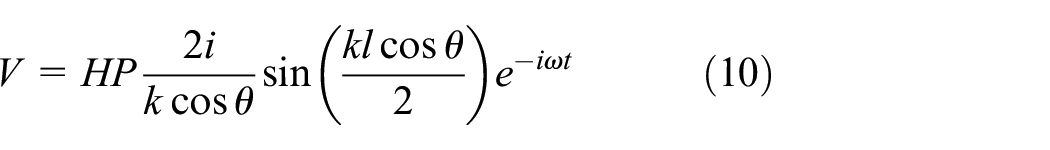
Two integration constants, H and P, are defined by
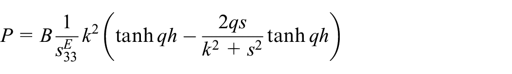
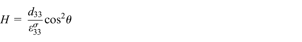
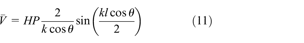
Finally, the voltage amplitude can be extracted as shown below
2.2. Directivity of the PZT fiber
We can further rewrite equation (10) in terms of a product between a frequency dependent sensitivity factor S and the strain amplitude, which yields

Here, sensitivity factor S is given by
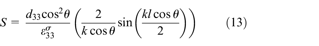
Above equation is a nonlinear function and it can be linearized with respect to

This approximation is valid at frequencies lower than 400 kHz as discussed by Matt and Scalea (2007).
2.3. Sensitivity results
Figure 2 shows the normalized sensitivity factor results at 0° and 45° of incidence under different frequencies, in which the PZT fiber length is set as 10 mm and its diameter is 0.8 mm. Figure 2 is computed using the linearization formulas in equation 14. Below 200 kHz, the proposed PZT fiber sensor is able to collect Lamb wave responses. Table 1 shows the plate and PZT fiber properties. Note that the sensitivity results in this study are normalized to demonstrate general trends. It is shown that the sensitivity factor S varies with actuation frequency. At lower frequencies (below 200 kHz), the larger value of S is observed. However, as the incident angle changes from 0° to 45°, corresponding responses decrease, which demonstrate good directional properties for PZT fiber sensors. At higher frequencies, because the wavelength is comparable to PZT fiber length, the results become complicated. A few zero points are observed due to the zero net charge in the PZT fiber. In summary, in order to effectively sense Lamb wave propagation, we need to comprehensively investigate the factors including actuation frequency, wavelength, and sensor material and dimension.
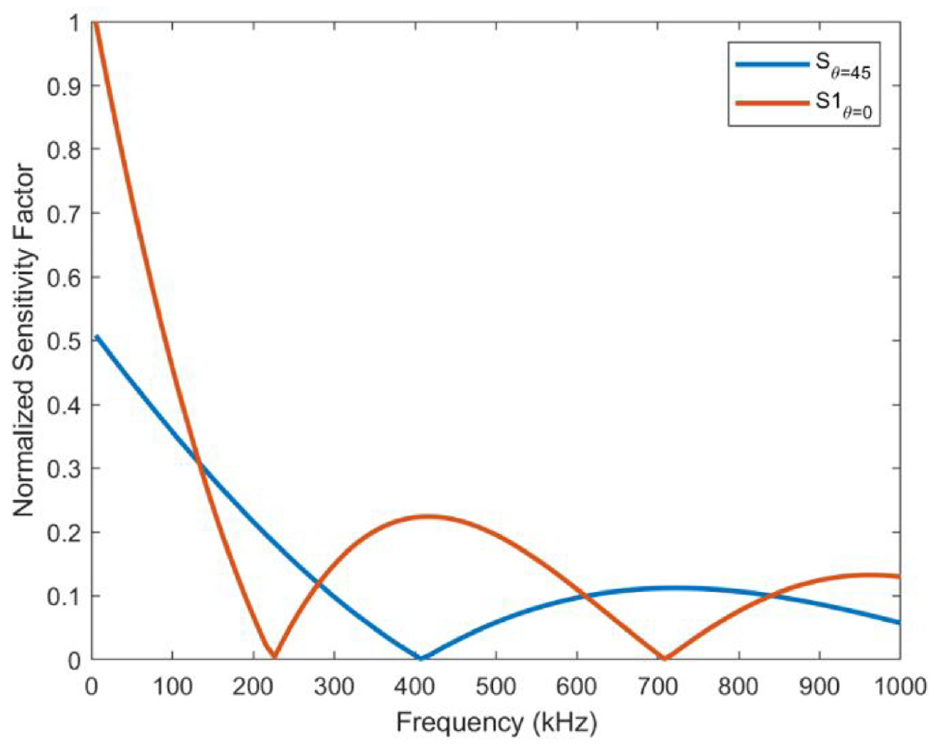
Normalized PZT fiber sensitivity at 0° and 45°.
PZT fiber and plate properties.
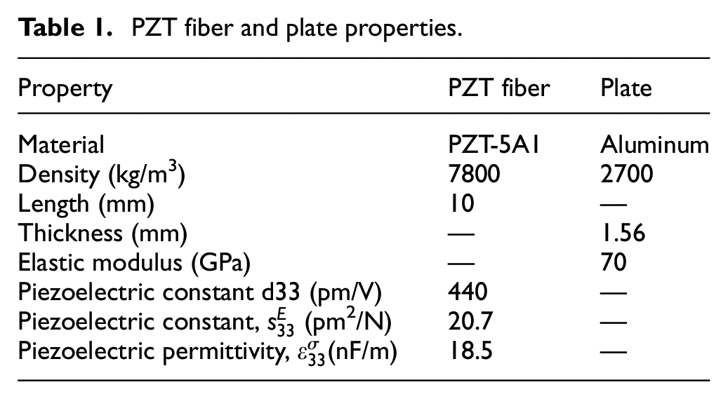
Figure 3 shows the sensitivity results when varying actuation frequency from 25 kHz to 100 kHz and PZT fiber sensor length. In order to better illustrate the sensor sizing effects on Lamb wave sensing, three cases were included, in which PZT sensor length is equal to 10 mm, wavelength, and half wavelength. The polar plot was adopted to show directional responses. As expected, a peanut–like shape was obtained at each frequency. Higher sensitivity values are observed when the Lamb wave propagation direction is in line with the PZT fiber orientation (e.g. 0° or 180°). When the PZT fiber sensor length coincides with the wavelength in each case, the polar response becomes complex. The maximum value is obtained when the PZT fiber length is equal to the half wavelength in all cases.

PZT fiber size and orientation effects on the responses under different frequencies: (a) 25 kHz, (b) 50 kHz, and (c) 100 kHz.
2.4. Algorithm to locate acoustic source
Consider a rosette with three PZT fibers A, B, and C arranged in the configuration as shown in Figure 4. The voltage response in each PZT fiber can be written as:
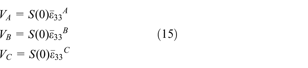
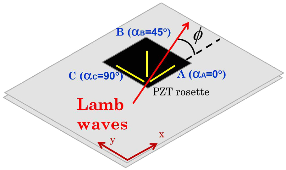
PZT fiber rosette to locate incoming Lamb waves.
Since all voltage responses share the same sensitivity term, three plane strain components, that is,
The transformation matrix T is:
3. PZT fiber rosette design and fabrication
3.1. Polarization
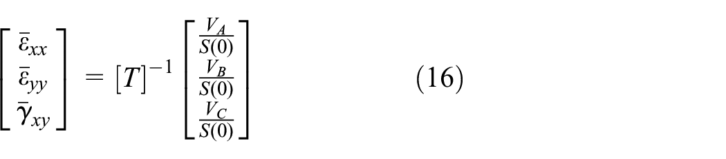
Figure 5(a) shows raw PZT fibers manufactured by Smart Material Corp. (Part No: A15A1-80150S, PZT5A type), which are spaghetti-like rods. These PZT rods are not polarized and not electroded. Each PZT fiber has a length of 150 mm and its diameter is 0.8 mm. Significant efforts were devoted to conduct in-house polarization for these PZT fibers. Key steps are summarized as below:
PZT fiber poling: (a) COTS Raw PZT fibers, (b) 3D-printed cartridge with hold fibers, (c) apparatus assembly, and (d) poled & electrode PZT fiber.
Cut PZT fibers to 10 mm long segments
Fill a 3-D printed cartridge with 10 mm PZT fibers as shown in Figure 5(b)
Assemble poling apparatus inside a container with silicone oil (i.e. dielectric media) as shown in Figure 5(c)
Connect positive and negative electrodes to a high voltage DC power supply (Model AU-20p7.5 from Matsusada Precision, Dallas, TX)
Conduct polarization for PZT fibers. Per instruction provided by Smart Material Corp., we need to apply 2 kV/mm field at room temperature for 15 min and the ramp-up and ramp-down cycling is greater than 1 min
Apply electrode to both ends for each poled PZT fiber as shown in Figure 5(d)
Note that one or two randomly selected PZT fibers in each batch were used to demonstrate sensing capability in a beam bending test. If successful, we kept that batch for PZT rosette assembly.
3.2. PZT fiber rosette
Analogous to a typical strain gage rosette, we designed our PZT fiber rosette based on the flexible circuit concept. First a flexible circuit layer was used to print electrical paths and interface to output measured voltage signals from three PZT fibers. Then, a plastic plate was employed to house three PZT fibers oriented in 0°, 45°, and 90° direction, respectively, and it was bonded to the flexible circuit layer. Finally, a top cover layer was applied to protect PZT fibers. The PZT rosette was manufactured by Tech-Etch (Plymouth, MA). Its footprint is approximately 15 mm by 15 mm. Figure 6 shows the PZT fiber rosette prototype. The flexible circuit layer is shown in Figure 6(a) (in yellow color), which is made of polyimide material. Its thickness is 0.0127 mm. Therefore, the interaction between the flexible circuit layer and PZT fiber is negligible. The plastic plate to house three PZT fibers is shown in Figure 6(b) (in black color). The top cover layer is shown in Figure 6(c). Key steps to assemble the rosette are outlined below:
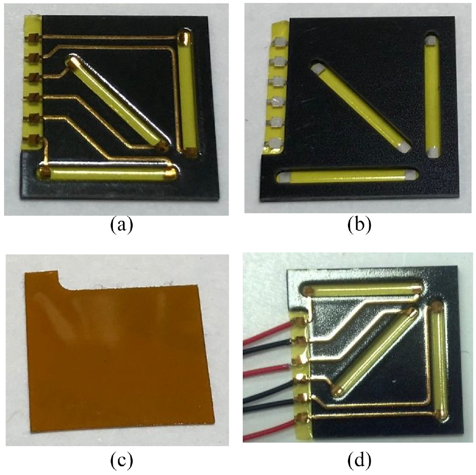
PZT fiber rosette prototype: (a) flexible circuit layer (in yellow), (b) plastic layer to house PZT fibers, (c) cover layer, and (d) final assembly.
Solder wires to the electric interface in flexible layer.
Drop PZT fibers in each slot and ensure electrical conductivity between fiber ends to printed electrical paths.
Bond cover layer on the top.
A fully assembled PZT fiber rosette is shown in Figure 6(d).
4. Experimental setup
In order to evaluate the PZT fiber rosette performance in terms of Lamb wave sensing and acoustic source localization, an aluminum plate (24 × 24 × 1/16inch) was used to conduct the test as shown in Figure 7, in which a grid of 2-inch squares was drawn for easy indication of locations. Two PZT fiber rosettes were bonded on the surface of the plate, denoted by “Sensor 1” and “Sensor 2.” In order to generate anti-symmetric bending waves under different frequencies, two PZT-5H circular disks (0.25 inch diameter) were bonded on opposite sides of the plate at the same X, Y location. Two of these pairs were employed to actuate the plate at two different locations, denoted by “Actuator 1” and “Actuator 2,” as shown in Figure 7. Accordingly, four cases were tested to collect Lamb waves based on the combination between two actuators and two sensors, which is defined below.
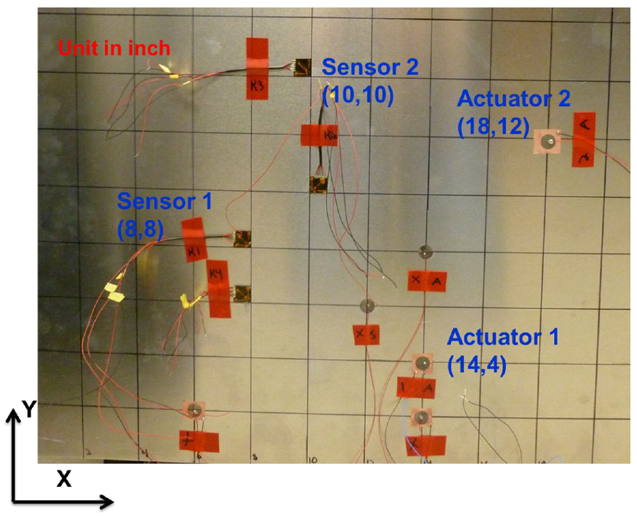
Aluminum plate with PZT fiber rosettes and actuators.
Case 1: Sensor 1 due to Actuator 1
Case 2: Sensor 2 due to Actuator 1
Case 3: Sensor 1 due to Actuator 2
Case 4: Sensor 2 due to Actuator 2
The LabVIEW program and a National Instruments Data Acquisition System (DAQ) (NI USB 6366) were employed in our test. First, a five-cycle Hanning windowed sine wave was generated in the DAQ. Then, the signal was amplified in order to drive the PZT actuator as outlined in our previous work on piezoelectric beam sensing (Venugopal and Wang, 2015). Actuation frequency was varied from 25 kHz to 95 kHz in increments of 10 kHz. Voltage responses were collected accordingly in each case. A lower sample rate had to be applied to collect three channels simultaneously. Meanwhile, cross talking among these channels were observed. In order to accurately capture high frequency Lamb wave responses, the highest sample frequency was used, which was 1 million per second. Under the same actuation conditions, we then collected each channel separately. Under each actuation frequency, the same actuation signals were consecutively applied 100 times to obtain a moving average response in each PZT fiber. Then the same process was repeated 3 times for all channels. The goal was to ensure repeatability and consistence of the signal in all channels under each actuation frequency.
5. Results
5.1. Lamb wave responses
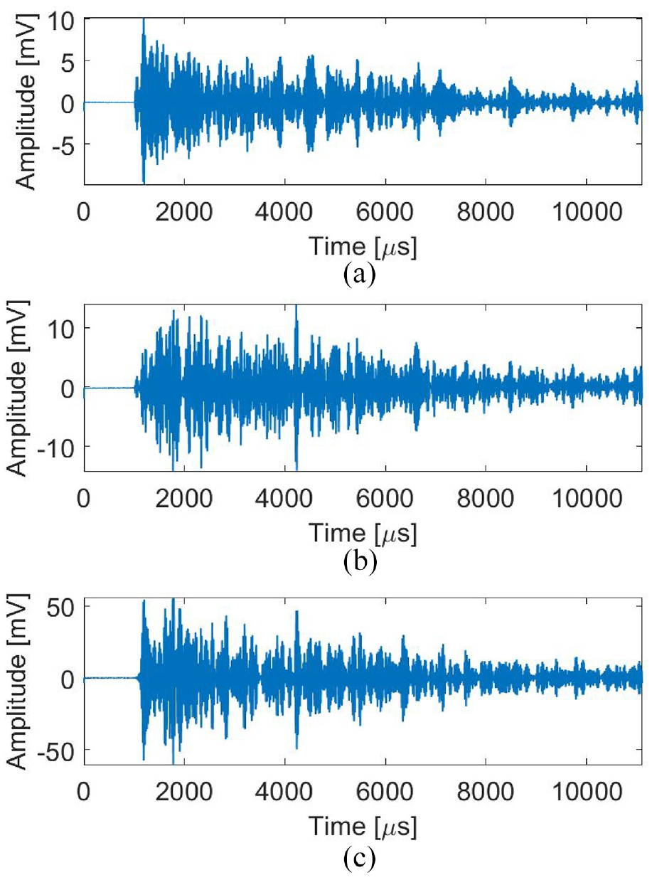
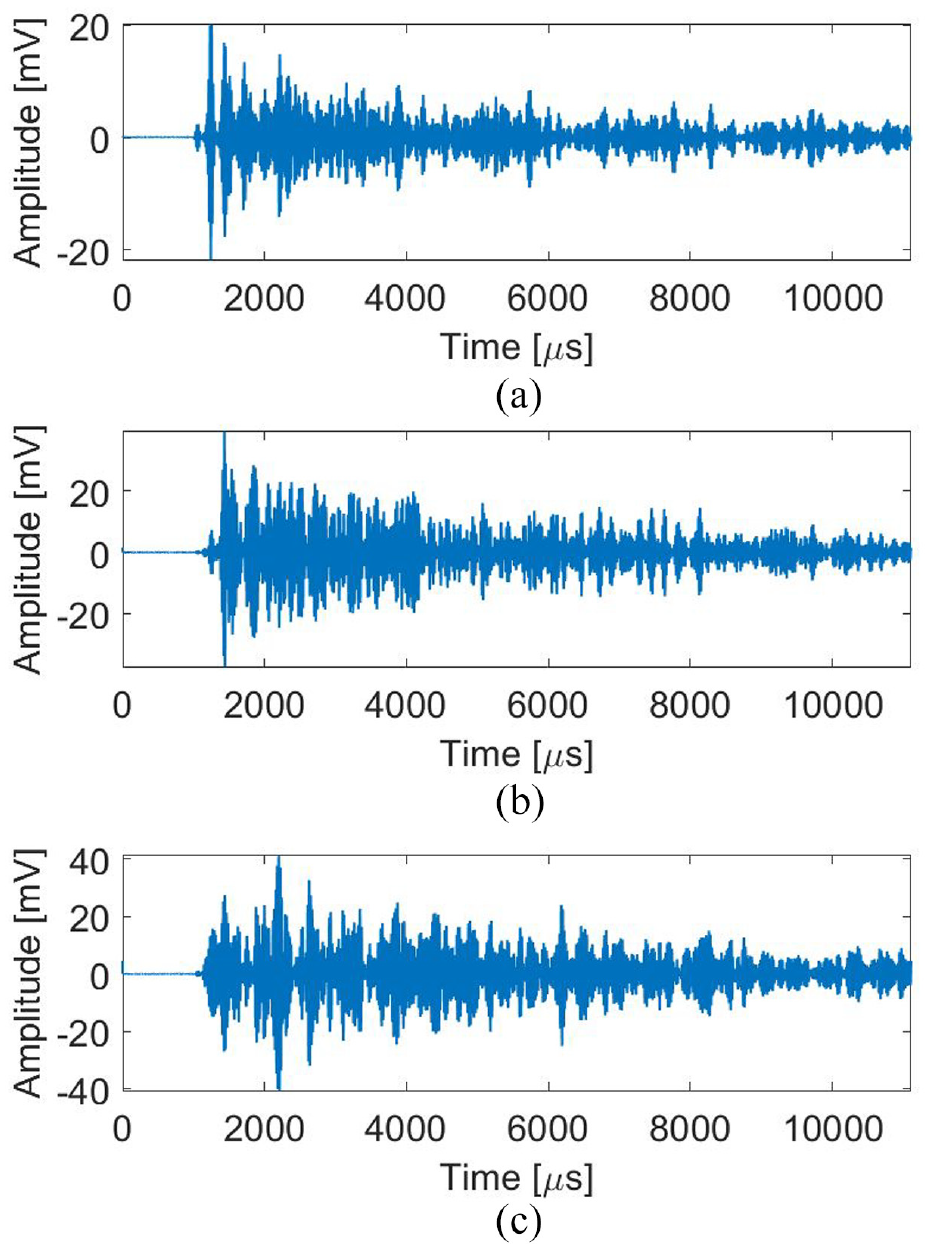
Figure 8 shows collected voltage responses in Case 1 at 25 kHz. Clearly, our PZT fiber rosettes are able to sense the Lamb wave propagation and capture its characteristics when traveling in a structure. Figure 9 shows 95 kHz results in Case 1. Similar collected voltage results are shown in Figures 10 to 12 for the rest three cases, respectively.
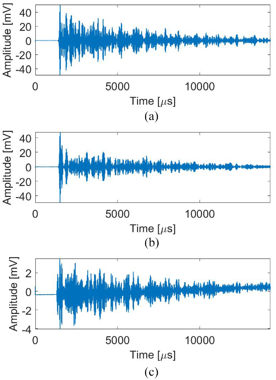
Case 1 at 25 kHz: (a) 0° fiber, (b) 45° fiber, and(c) 90° fiber.
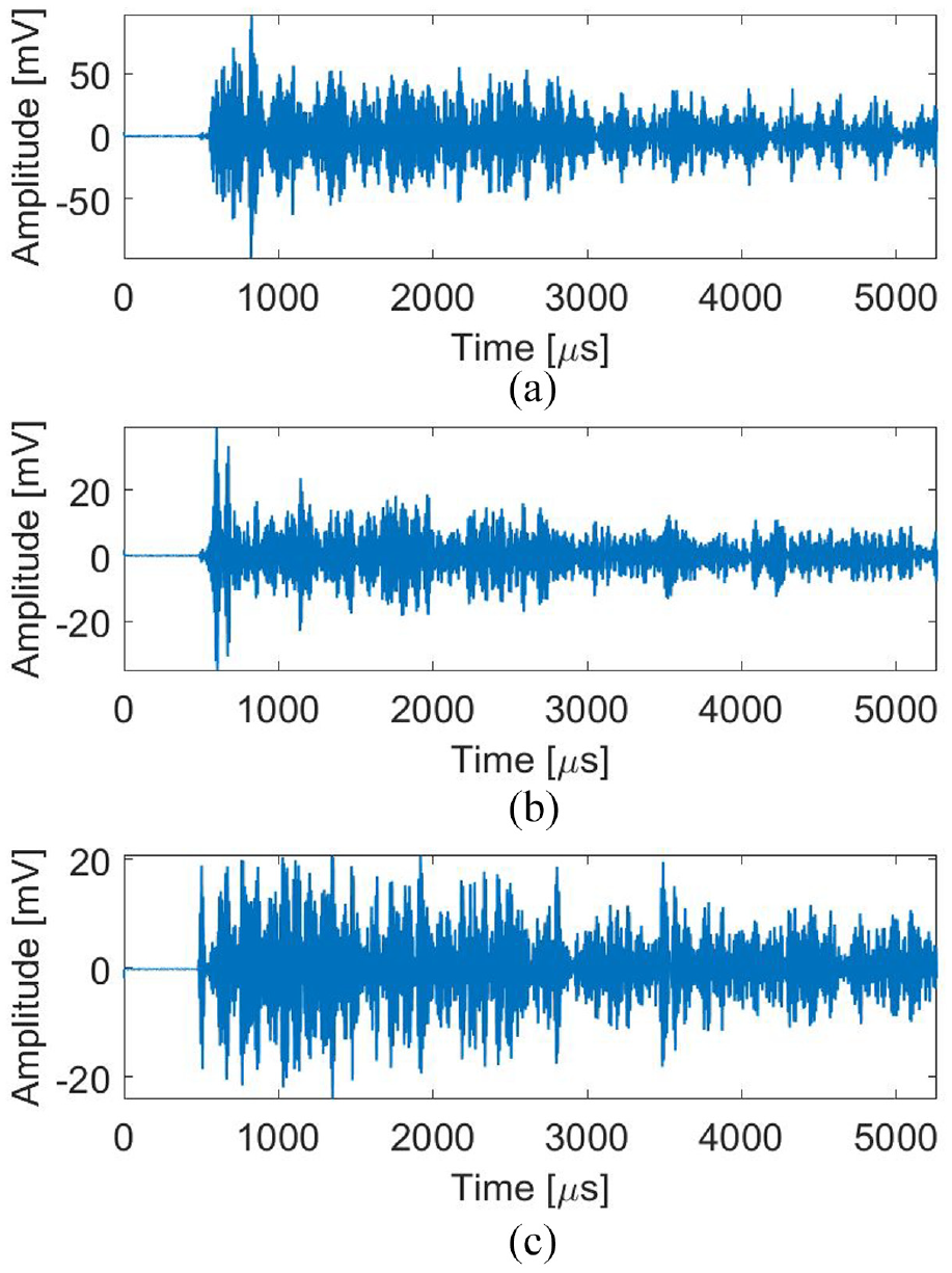
Case 1 at 95 kHz: (a) 0° fiber, (b) 45° fiber, and(c) 90° fiber.
Case 2 at 45 kHz: (a) 0° fiber, (b) 45° fiber, and(c) 90° fiber.
Case 3 at 45 kHz: (a) 0° fiber, (b) 45° fiber, and(c) 90° fiber.
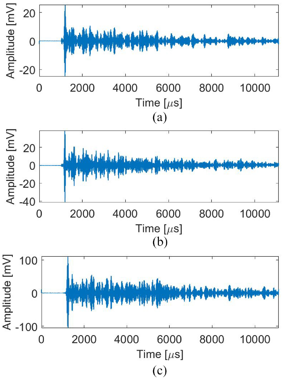
Case 4 at 45 kHz: (a) 0° fiber, (b) 45° fiber, and(c) 90° fiber.
5.2. Acoustic source localization
In order to locate an acoustic source, we need to use the instantaneous response measured from the PZT fiber rosettes, as shown in Figure 13. First, the peak voltage value can be determined from the measurements in three PZT fibers. Then, voltage responses can be extracted accordingly from other PZT fibers. Finally, the acoustic resource angle can be calculated using equation (18). Note that we have tried different approaches to extract voltage responses to calculate the source angle. The peak voltage values provide best results. New algorithms are expected to further improve such calculation.
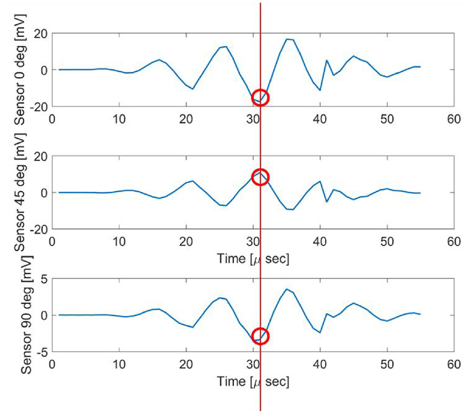
Signal selection from instantaneous Lamb wave responses for acoustic source angle calculation.
Note that we need to update the PZT fiber orientation angles (as shown in equation 14 and Figure 4) accordingly in each case in order to compute the source angle. Figure 14 shows the acoustic source angle results in case 1 (Sensor 1 and Actuator 1). The actual angle is −33.69°. The inferred angle is approximately −22°. Figure 15 shows the case 2 (Sensor 2 and Actuator 1) results. The calculated angle agrees well with actual value. Figure 16 shows the case 3 (Sensor 1 and Actuator 2) results. In this case, a small variation is observed under different frequencies. Figure 17 shows the case 4 (Sensor 2 and Actuator 2) results. Large error is observed between actual and calculated angles. At lower frequencies (25 and 35 kHz), the prediction has a higher variation however, at high frequencies, the angle results are more consistent. As discussed in section 2, the PZT fiber length is small in comparison to the wavelength in each frequency. But, the results indicate that higher actuation frequencies result in better accuracy and consistency.
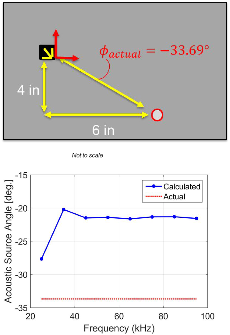
Case 1: Sensor 1 and Actuator 1.
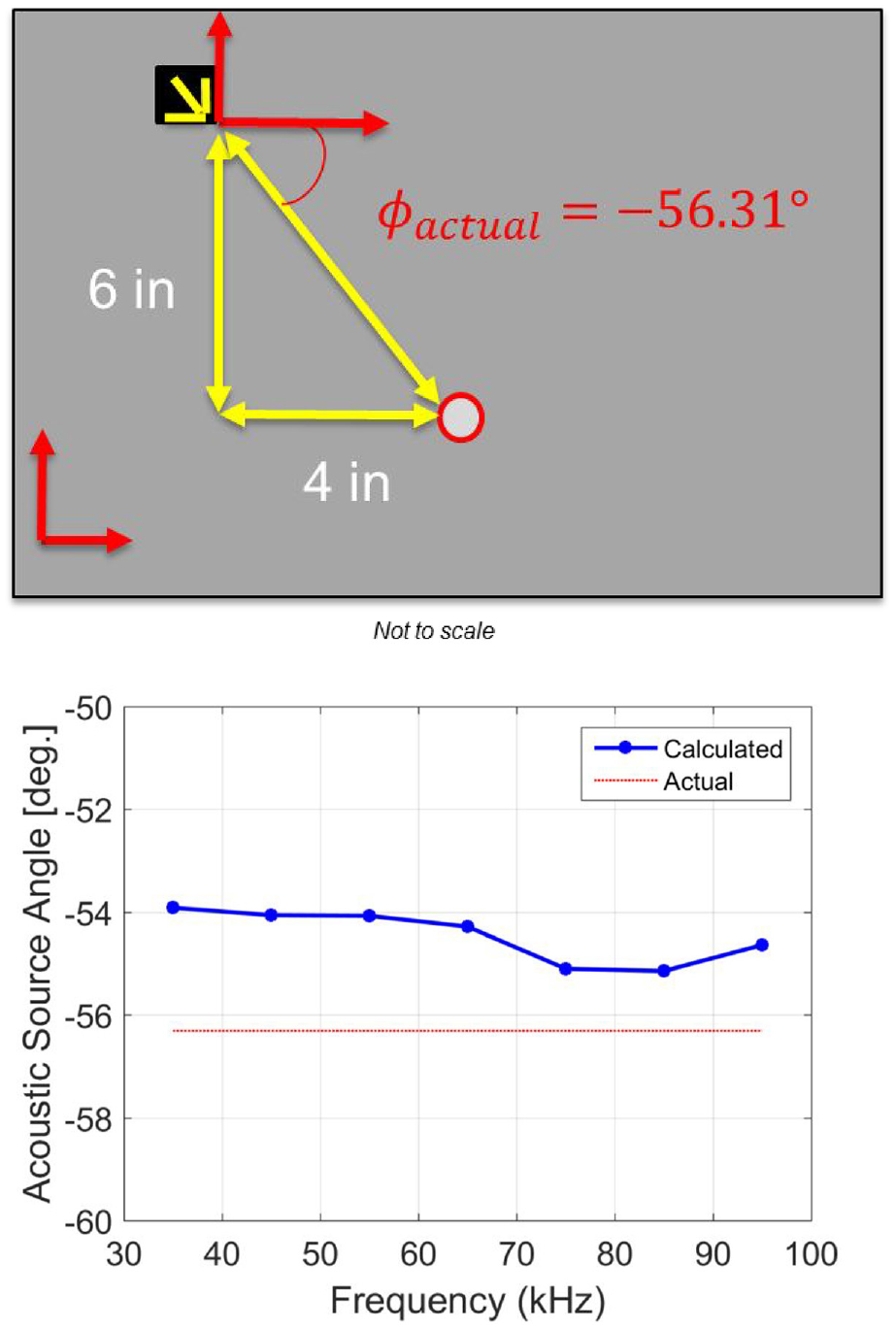
Case 2: Sensor 2 and Actuator 1.
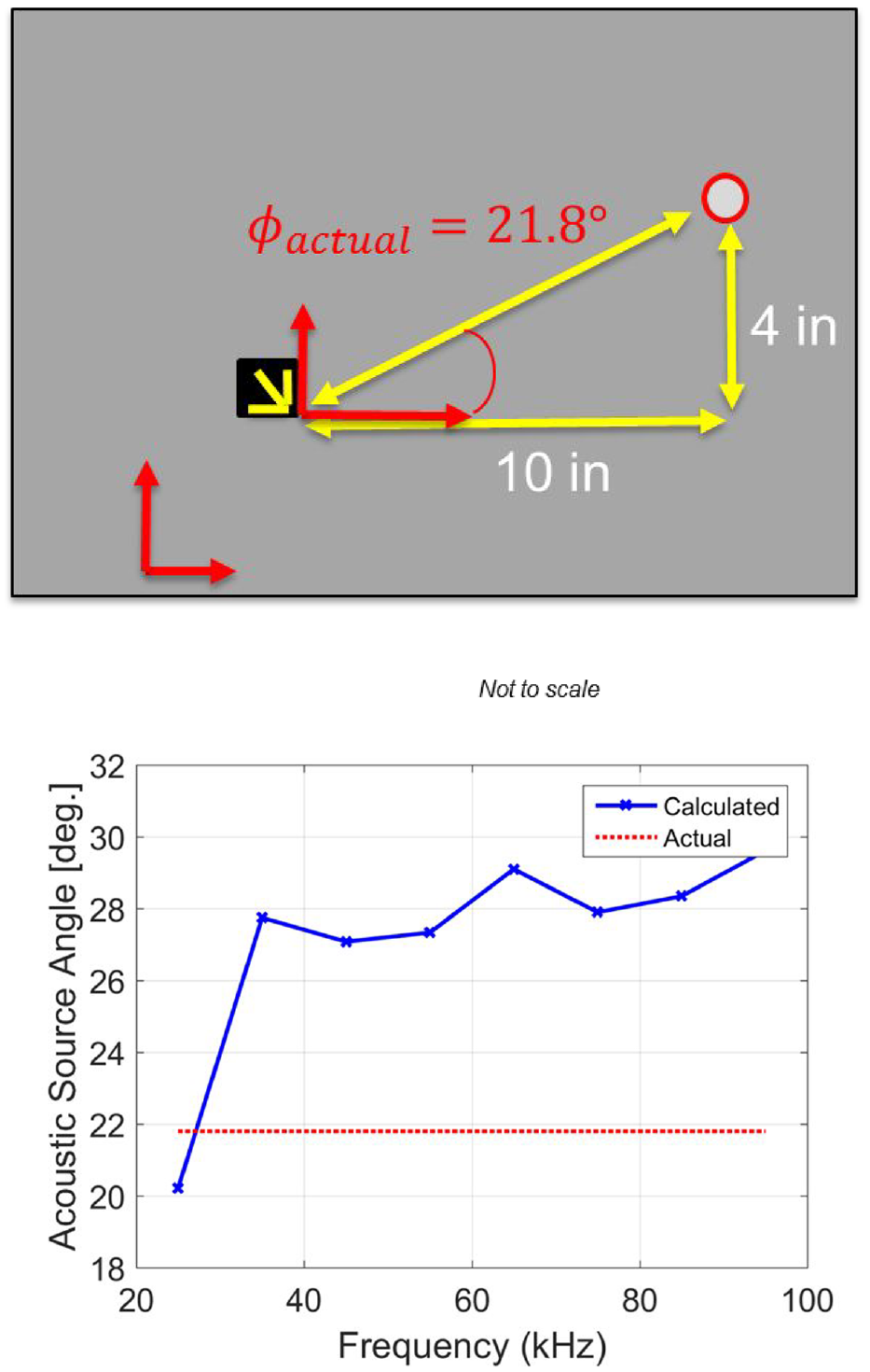
Case 3: Sensor 1 and Actuator 2.
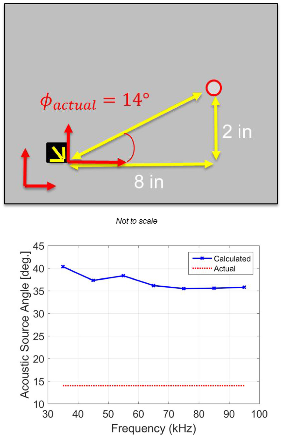
Case 4: Sensor 2 and Actuator 2.
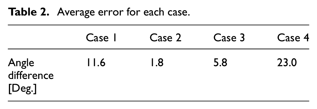
The average errors in each case are presented in Table 2. There are some variations between actual and derived angles. But in all cases, the direction of the acoustic source is clearly identified. Angle predictions can be improved by exploring other algorithms. It must be emphasized that a slight misalignment during instrumentation could contribute significantly to these angle calculations. In addition, quality control of these in-house polarized PZT fibers could be the cause. Some uncertainties include: the variation in each PZT fiber, polarization, electrode conditions, and adhesive inconsistency. These uncertainties could affect the sensing capability of the PZT fiber rosette.
Average error for each case.
In summary, this is the first attempt to explore the d33 effects in PZT fibers. Refinements are expected to enhance the performance of the proposed PZT fiber rosette in SHM applications.
6. Conclusion
A PZT fiber rosette concept was proposed in this paper, which is an alternative cost effective solution to PZT array systems for Lamb wave sensing. In-house PZT polarization and PZT fiber rosette assemblies were demonstrated, which can benefit future research efforts. Based on the analytical results, it has been demonstrated that a PZT fiber shows a good directional property for Lamb wave sensing due to d33 effects. Different voltage amplitudes were observed in the instantaneous Lamb wave responses from three PZT fibers, which led to a further illustration of the directional sensing capability of PZT fibers. We were able to collect voltage signals under different actuation frequencies to capture the Lamb wave propagation characteristics. Moreover, these collected voltage data allow us to successfully locate acoustic sources under different sensor and actuator configurations. The performance of the proposed PZT fiber rosette was successfully demonstrated in terms of sensing capability and acoustic source localization. Key remarks are shown below:
A PZT fiber shows a good directional property due to the d33 effect as demonstrated both analytically and experimentally.
A simple algorithm was employed to calculate the principal strain direction in order to locate acoustic sources in Lamb wave based SHM applications.
In-house PZT fiber polarization was conducted and associated apparatus was demonstrated.
A PZT fiber rosette was designed and prototyped, which can be assembled easily to benefit future research efforts.
Voltage signals were successfully collected using PZT fiber rosettes under different actuation frequencies ranging from 25 kHz to 95 kHz.
These collected voltage data allow us to successfully locate acoustic sources under different sensor and actuator configurations.
With further refinement of the fiber design, fabrication, calibration and quality control, the fiber and subsequently the rosette sensors can yield better performance in terms of accuracy and longevity.
Footnotes
Appendix
Declaration of conflicting interests
The author(s) declared no potential conflicts of interest with respect to the research, authorship, and/or publication of this article.
Funding
The author(s) received no financial support for the research, authorship, and/or publication of this article.