
Abstract
In recent decades, various single-phase drive ultrasonic motors have emerged, and only a single excitation signal is used in their working states. Single-phase driven ultrasonic motors have the benefits of most ultrasonic motors, as well as the advantages of a simple driving circuit construction, low cost, high design flexibility, and high reliability, among others. According to the working principles, they are divided into three types: the vibration mode alternating type, the vibration mode coupling type, the vibration mode converting type. This paper summarizes various types of single-phase ultrasonic motors. The three types of the working principles and its representative structures are explained; output performances of the single-phase ultrasonic motors are described; then, practical and potential applications of the single-phase ultrasonic motors are introduced; finally, the research of single-phase ultrasonic motors are reviewed, and its development prospect is prospected. This review is helpful for a comprehensive understanding of single-phase drive ultrasonic motors. This paper offers the groundwork for the development of a novel single-phase driven ultrasonic motor with improved mechanical output.
Keywords
1. Introduction
Ultrasonic motors, as one type of the piezoelectric motor, can directly output motion without transmission systems. Using the inverse piezoelectric effect, the ultrasonic motor converts electric energy into micro vibration (micron or nano level); further, under the friction coupling, the micro vibration is transformed into macro motion. Small size, simple construction, rapid reaction, flexible design, high positioning accuracy, and high displacement resolution are key advantages of ultrasonic motors (Chen et al., 2011; Uchino, 1997; Wang et al., 2019a, 2019b; Xu et al., 2018; Zhao, 2011). From the viewpoint of the number of excitation signals, they can be categorized into single-phase driven type (Sashida and Kenjo, 1993; Tamura et al., 2011; Wischnewski and Moukouri, 2008; Xu et al., 2019b), two-phase drive type (Jiang et al., 2018; Yang et al., 2013, 2015, 2016), and multi-phase driven type (Deng et al., 2019a, 2019b; Liu et al., 2019a, 2019b).
Based on the vibration state of the stators, piezoelectric motors can be classified as resonance and non-resonance. And the resonance type piezoelectric motors are usually called ultrasonic motors (USM). The non-resonant single-phase piezoelectric motors are studied (Cheng et al., 2015; He et al., 2018; Liu et al., 2016b; Zeng et al., 2014; Zhang et al., 2019; Zhou et al., 2014). There is a special type (also known as inertia drive piezoelectric actuator) piezoelectric motor, which convert the impact or inertia of mass into linear or rotary motion of the mover (He et al., 2018; Liu et al., 2016; Zhang et al., 2019). The operating concept is realized using asymmetric drive voltage, such as a sawtooth waveform. And the inertial type motors change the drive waveforms to change the moving direction. Inertial motors operate in a quasi-static condition, which are disadvantage for the piezoelectric motor’s high-power output. There is no “vibration mode” in such a non-resonant type design, which operates under low driving frequencies. This paper focuses on the ultrasonic motors.
The two-phase type ultrasonic motors usually drive the runners by compositing of two vibration modes to form elliptical trajectories (Xu et al., 2016, 2017, 2019; Yang et al., 2018; Zhou et al., 2016); generally speaking, this operating principle makes two-phase type ultrasonic motors need two orthogonal working modes with close frequency. Thus, two same frequency excitation signals with 90° phase shift are required. However, the structures of the two-phase drive type ultrasonic motors are relatively complex; the consistence demand of the frequencies of two orthogonal working modes is high. Multi-phase ultrasonic motors need multi-channel independent power amplifier, as well as the regulation of phase shift when changing the actuator’s movement direction, which makes the drive circuit complex. In addition, the multi-phase drive actuator needs to work in the coupling mode of mutual degeneracy; and it is easy to lose degeneracy because of preload and heating; so, it is easy to work unsteadily, which affects its practical application.
The single-phase driven ultrasonic motors usually drive the runners by oblique line trajectories; during the working state, only one-phase excitation signal is needed (Ko et al., 2006; Okamoto and Yoshida, 1998; Peter et al., 2007; Tamura et al., 2007b; Xu et al., 2021). Thus, the miniaturization of the drive circuit can be realized by using the single-phase circuit (Juang and Tsai, 2009); the loose requirements on the frequency consistency of the working modes increase the design flexibility; the installation and debugging times are reduced, and the mechanical and electrical structures are simple and low-cost.
The unified classification of the single-phase driven ultrasonic motors has not been discussed. According to the output motion, the single-phase ultrasonic motors can be divided into the linear ones (Chen et al., 2010; Ho and Shin, 2013; Iijima et al., 1989; Li et al., 2015) and rotary ones (Dabbagh et al., 2017; Jin and Zhao, 2006; Li et al., 2017; Pang et al., 2012; Park et al., 2006). And from the waveform used in the ultrasonic motors, traveling wave type (Guo and Zhao, 2008; Seemann, 1996) and standing wave type (Aoyagi and Tomikawa, 1996; Pang et al., 2011; Park and He, 2012; Wang et al., 2018; Zhao et al., 2016) are the main two types. To the best of our knowledge, although there are some reviews having been reported for piezoelectric actuator techniques, the discussion on single-phase driven ultrasonic motors is still not given. Moreover, based on the unique advantages of single-phase ultrasonic motors, it is also meaningful to present the progress and trends of single-phase driven ultrasonic motors.
This paper presents a complete overview of current works on single-phase driven ultrasonic motors, which is arranged as follows. The first section is the introduction. The second section includes thorough explanations of single-phase driven ultrasonic motors, as well as their operating mechanism and typical structures. The third and fourth sections are dedicated to performance analysis and practical implementation, respectively. In the last section, relevant conclusions are given, and the prospects of single-phase drive ultrasonic motors are looked forward to.
2. Working principles and configurations
In essence, there are generally three types of the single-phase driven ultrasonic motors based on the operating principles. We call it the vibration mode alternating type, which alternately use vibration modes to realize bi-directional motion. There are two ways to obtain the bi-directional motion: one is to excite the piezoelectric elements alternately; the other is to switch the excited vibration modes alternately (Li et al., 2017).
The second is named the vibration mode coupling type. The drive trajectories of which are generated based on the coupling effect of vibration modes. Usually, the oblique line trajectories or the elliptical trajectories are generated.
The third one is vibration mode converting type, and vibration mode is converted to form drive trajectory. The vibration mode converting type ultrasonic motors usually convert the common vibration mode by designed stator, and various specially shaped structures are used to convert the common vibration modes, such as longitudinal vibration. Bio-inspired ultrasonic motor is a kind of typical vibration mode converting type ultrasonic motor, which imitates the movement in nature to realize output motion.
2.1. Vibration mode alternating type ultrasonic motors
Hsiao and Tsai (2010) suggested a single-phase ultrasonic motor with a perpendicular electrode vibrator, as shown in Figure 1, When the electrode 1 was in the excited state and the electrode 2 was in the free state, the vibration mode in the left figure of Figure 1(b) was excited. Then, through friction coupling, a slider was pushed based on oblique line trajectory. We could change the direction of the oblique line trajectory by changing the excitation of the electrodes, so as to control the motion direction. And the designed ultrasonic motor produced output with a velocity of 84.2 mm/s and a push strength of 1.79 N. However, the coupling factor of the proposed ultrasonic motor was low, which was only 0.135; the mechanical characteristics were relatively poor, which was mainly caused by the nonuniform driving electric field.
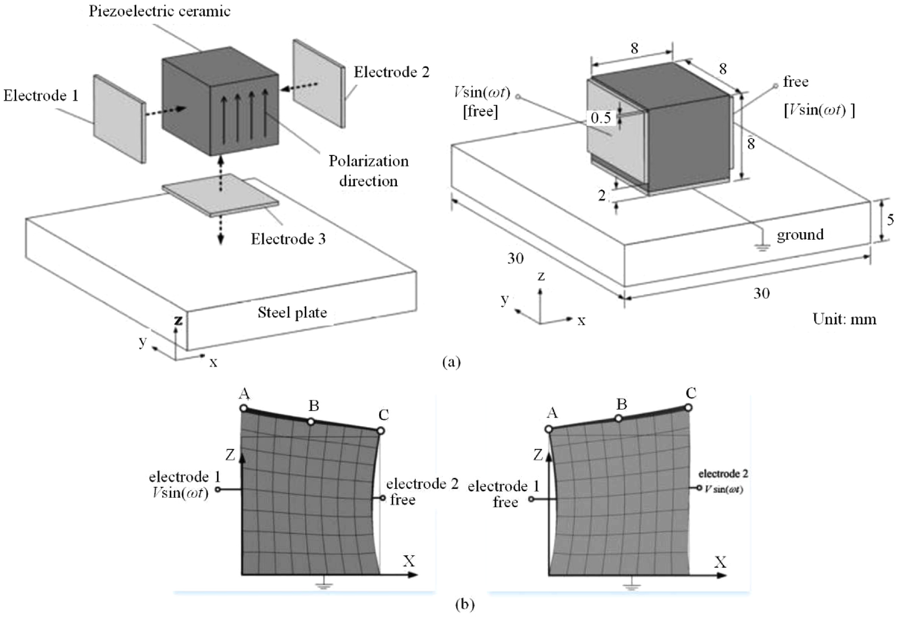
Schematic of vibration mode alternating type linear piezoelectric transducers by Hsiao et al: (a) vibration mode alternating type linear piezoelectric transducers structure and (b) vibration modes (Hsiao and Tsai, 2010).
A single-phase ultrasonic motor with two square plate vibrators was suggested by Yokoyama et al. (2013), as shown in Figure 2, V-shaped beams connected two square plate vibrators. When a square plate vibrator was activated in working status (using breathing vibration mode); in the same time, the other vibrator was electrically opened, thus an oblique trajectory was generated to push a slider. The illustrated single-phase driven ultrasonic motor could drive a slider with velocity of 100 mm/s and pushing force of 3.5 N under excitation voltage of only 5 V. In addition, the moving direction could be switched by changing the work sequence of the square plate vibrator, and the output performances were similar in two moving directions. This kind of single-phase driving ultrasonic motor has simple structure, high output performance under low excitation voltage of only 5 V, which has potential application value in spacecraft and other fields.
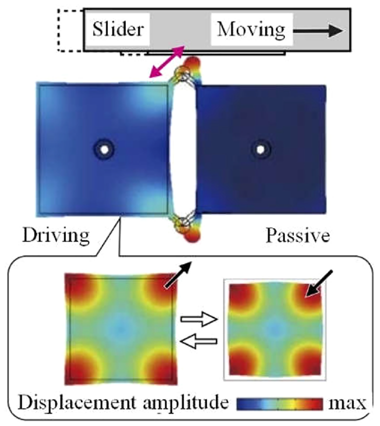
Working principle of single-phase piezoelectric actuator using breathing vibration mode by Yokoyama et al. (2013).
Chen and Huang (2011, 2012) proposed a single-phase driven ultrasonic motor characterized by tapered stator and a slider with an obliquity angle. The stator had two working status: one was the symmetric vibration mode in YZ plane, the other was bending vibration mode in ZX plane. Since the inclination direction of the driving trajectory could be switched to change the movement direction of a slider, the stator’s operation mode had to be adjusted as well.
Vibration mode B3 and B4 of a rectangular plate-type vibrator were used to generate bi-directional actuating by He et al. (1998). Therefore, the vibration modes B3 and B4 refer to the third-order and fourth-order of the bending vibration modes. For the free-free beam, the third-order and the fourth-order bending vibration modes have four and five nodes, respectively. Vibration mode B3 or B4 of a rectangular plate vibrator was used to generate bi-directional actuating by He et al. (1998). Bending vibration mode B4 was used to create the projections on the left sides of the wave crests depicted whereas B3 was utilized to create the projections on the right sides. Projections in the area II could produce an actuating force in left direction under vibration mode B4 or in right direction under vibration mode B3. In addition, projections, such as in area II, could be used in area I to provide bi-directional actuation forces. Thus, by alternating the vibration mode, the directions of the actuating force would be turned. The ultrasonic motor had a maximum speed of 200 mm/s and a maximum force output 150 gf (gram force was the unit of force, which referred to the unit of gravity of 1 G mass material. In addition, 1 N = 102 gf), and the resolution was less than 0.1 μm. Fan et al. (2018) designed a high thrust-weight ratio single-phase driven ultrasonic motor. (which was the ratio between the maximum thrust and the weight of the motor) The first-order bending vibration mode and second-order bending vibration mode were utilized to obtain bi-directional motion, and the right oblique movement or the left oblique movement were generated on the drive foot. Changing the resonant frequency and electrode was the method to realize the bi-directional motion. The thrust-weight ratio of the prototype ultrasonic motor reached 134.69, with the overall weight of stator was 1.0 g. However, due to the different vibration modes used in bi-direction, the mechanical output of the bi-directional motion was not consistent.
2.2. Vibration mode coupling type ultrasonic motors
Bi-directional ultrasonic motors using mode coupling between the longitudinal and bending modes caused by the asymmetry shape (Aoyagi and Tomikawa, 1993; Aoyagi et al., 1992; Tamura et al., 2007) or crystal anisotropy (Tamura et al., 2008, 2010) of the stator were reported; the coupling effect could provide a pair of modes by asymmetry shape or crystal anisotropy; coupling mode is allotted to push the load in each direction; however, the output performances are not equal in each moving direction. Utilizing two same bending modes of a circle stator (Aoyagi et al., 2002; Takano et al., 1992, 1994, 1999), the same output performances in reverse direction were obtained; however, this type of structures was not suitable for effectively moving a linear slider directly.
A single-phase driven ultrasonic motor adopting obliquely polarized piezoelectric ceramic transducers was designed by Ishii et al. (1993), as shown in Figure 3. The direction of polarization was oblique to the electric field, as a result, the longitudinal and the torsional vibrations were activated at the same time. Under the combined action of longitudinal and torsional vibrations, the ultrasonic motor could operate stably. In addition, a relatively low revolution speed of the proposed prototype was obtained compared with that of the hybrid-type ultrasonic motor.
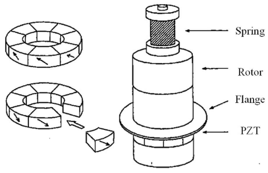
Obliquely polarized piezoelectric ceramic rings and construction of the ultrasonic motor (Ishii et al., 1993).
A sandwiching ultrasonic motor was invented by Ma et al. (2016), the stator was composed of a T-shaped steel body and two piezoelectric plates (had opposite poling direction in thickness direction). A steel disk was used as the rotor. Single-phase signal applied on one piezoelectric plate could excited two orthogonal bending modes, thus a wobble motion is created. With only one plate activated at a time, the observed displacement spectrum was the ellipses. The elliptical movement could be produced with an input voltage of 40 VP-P and the frequency band of 44.3–45.1 kHz. In addition, the driven trajectory was oblique line or approximate oblique line with the frequency of 45.3 kHz. The bi-directional movement could be realized by operating the opposite side piezoelectric device. However, the structure of the clamping device is complex.
A tuning-fork single-driven ultrasonic motor using dual-mode was designed in Friend et al. (2003). This proposed ultrasonic motor combined the tuning fork motion with the lifting motion to generate bi-directional diagonal motion. The multilayer piezoelectric material was installed on the stator with swaging. By positioning the piezoelectric material (PZT multilayer piezoelectric actuators) at an inclination, θ, simple tuning-fork motions combined with fork-lifting motions, could induce diagonally movement along the contact surface. The output performances of the prototypes were: a speed without load of 16.5 cm/s and a force of 1.86 N.
The nut-type ultrasonic motor employing two third-order bending modes (which were orthogonal to each other) was designed by Chen et al. (2015a). The rotor was driven by the stator’s traveling wave. With an AC signal of a frequency between two mode frequencies applying to one of the two piezoelectric plates, working modes were both excited with a phase difference to form the traveling wave. The method of switching of rotation direction was to alter the direction of the traveling wave by changing the connected piezoelectric plate.
The theory of two in-plane modes of a ring excited by a single-phase drive was discussed (Cagatay et al., 2003; Koc et al., 2000, 2002; Peter, 1987; Sashida, 1982; Ueha et al., 1993). Tubular ultrasonic motors utilizing only one drive signal were developed (Aoyagi et al., 2002; Cagatay et al., 2003; Chen et al., 2015; Friend et al., 2003; Ishii et al., 1993; Koc et al., 2000, 2002; Ma et al., 2016; Takano et al., 1992, 1994, 1999; Tamura et al., 2010; Ueha et al., 1993); This motor has two orthogonal degenerative bending modes, and only one excitation signal was supplied to one PZT element at a frequency between the resonance frequencies of the two modes, activating both modes and providing oscillating movement. The rotation direction could be reversed by changing the voltage to the other PZT element. This form of motor necessitated the coupling of two degraded vibration modes, therefore the tubular PZT composite structure had to be effectively developed to reduce the difference in the two modes’ resonance frequencies.
A model of a ring vibrator connected with a little mass was proposed by Ueha et al. (1993), (Kurosawa and Ueha, 1991). Two vibration modes were generated from the degenerate mode when the amount of the mass was appropriate. Two vibration modes were orthogonal with each other and were slightly different in resonance frequencies. Thus, only one electric source was needed to generate a traveling wave to drive an ultrasonic rotary motor. The merit of this proposed ultrasonic motor was that only using a single-phase source, a rotary ultrasonic motor based upon a traveling wave was driven. In addition, the rotary direction of the ultrasonic motor could be changed by changing the driving elements.
A single-phase linear ultrasonic motor utilizing the in-plane expanding and bending modes was designed by Chen et al. (2015). And two modes were excited synchronously to produce the drive trajectories (two orthogonal straight-line trajectories). Single-phase voltage was applied on A or B (the ceramic square plate is divided into two areas, A and B, which are used as voltage inputs, and the bottom of the square plate is used as a common ground) to switch the motion direction of the runner. As a micro-actuator, the ultrasonic motor had potential application prospects in the fields of minimally invasive surgical instrument, precision engineering, and micro-robots.
A standing-wave type linear ultrasonic motor was suggested by Liu et al. (2016). A longitudinal-bending hybrid mode was created, which was neither longitudinal nor bending mode. When one signal voltage with frequency of the first longitudinal and third bending resonance frequency and the boundary was unsymmetrical, the longitudinal-bending hybrid mode was formed. The proposed linear ultrasonic motor was tested to a transient analysis. With a sine voltage of 400 Vp-p and an working frequency of 29.4 kHz, the maximum velocity and thrust force were 891.3 mm/s and 39.2 N, respectively. However, the frequency of this longitudinal-bending hybrid mode has a quite high consistent demand.
A single-phase bending-bending ultrasonic motor was suggested by Tian et al. (2020). In this paper, 8-shaped trajectories were utilized to drive the runner. And the single-phase signal mixed two sine signals with a frequency ratio of 1:2. The way to switch the moving direction of the proposed motor was to change the phase shift between the high and low frequencies of the mixed signal. Compared with the commonly used traditional oblique line and elliptically driven trajectories, single-phase ultrasonic motor used the 8-shaped trajectories.
2.3. Vibration mode converting type ultrasonic motors
Flueckiger et al. (2007) designed a single-phase linear ultrasonic motor that used the longitudinal vibration mode of ceramics to obtain a specific motion of the stator. The actuator was pushed forward by the eigenmode deformation at 84 kHz; the actuator was pulled backwards by the eigenmode deformation at 69 kHz. Especially, during the first part of a deformation cycle, the stator driving foot bended toward the contact point. A force was formed due to frictional contact between the driving foot and the guide, causing the actuator to move in a linear manner. Contact was lost when the driving foot bended far from the guide in the second section of the deformation cycle. In addition, traditional elliptical trajectories were not used at the driving tip. Rather, the longitudinal vibration mode was translated into the special motion of the stator, the resonator’s specific deformation corresponds to a pushing or pulling motion, respectively. Forward and backward movements are generated using signal frequencies of 84 and 69 kHz, respectively.
In recent years, new single-phase drive ultrasonic motors with basic bionic structures have been developed. Zhang et al. (2017), for instance, suggested a frog-shaped linear ultrasonic actuator. and W-type structure was used to convert the longitudinal vibration mode to realize linear drive.
Inspired by the rock-climbing sport, the ultrasonic motor with a H-shaped construction and a guide was designed by Pan et al. (2017) This proposed motor, unlike the inchworm motor, was operated by a single-phase signal. The longitudinal vibration mode was converted by the H-shaped structure to drive the guide.
A single-phase stepping ultrasonic motor was suggested by Shi et al. (2009). B12 mode of a circular stator was converted into the motion of rotor. In the open-loop control, the proposed ultrasonic motor had the characteristics of no cumulative errors.
In addition, by examining more closely the working principles of the single-phase ultrasonic motors, some ultrasonic motors can only realize unidirectional motion output. For the bi-directional single-phase driven ultrasonic motors, it indicates that there are three methods for changing the moving direction: drive waveforms, drive electrodes, and drive frequencies (Aoki and Horiuchi, 1997).
3. Performances of the single-phase driven ultrasonic motors
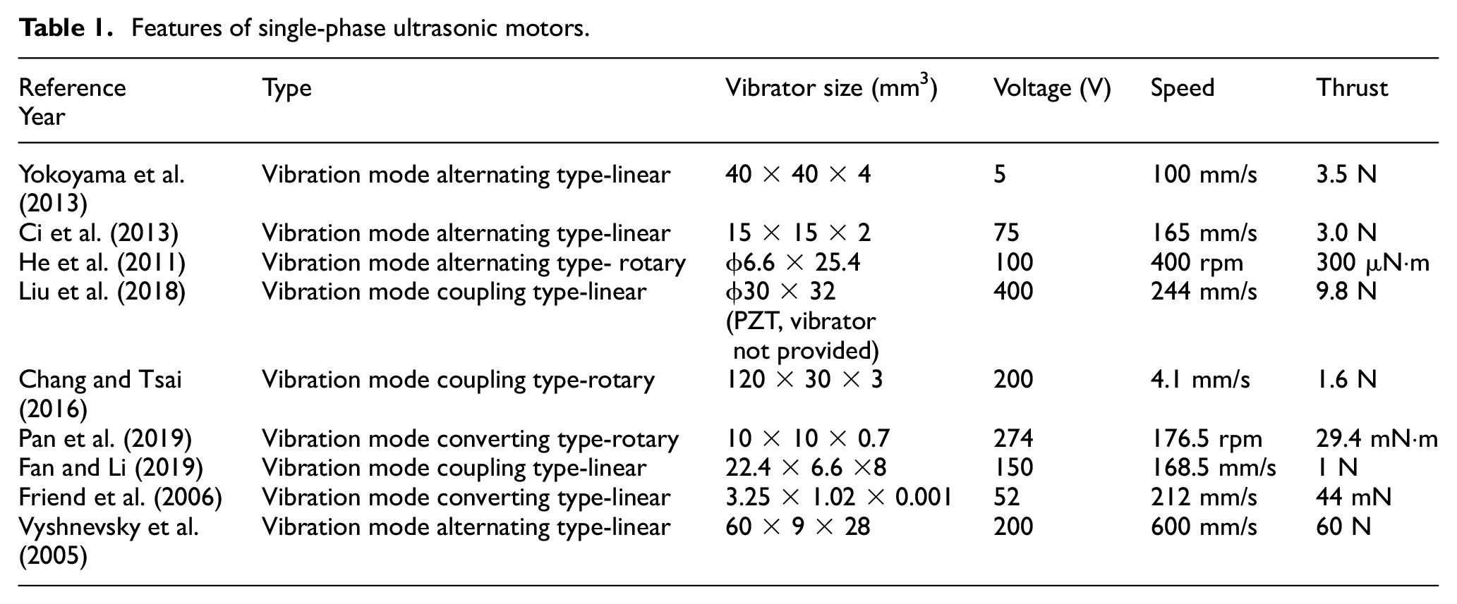
The characteristics of some representative single-phase driven ultrasonic motors in recent years are listed in Table 1. And they cover rotary and linear ultrasonic motors, including the three types of ultrasonic motors.
Features of single-phase ultrasonic motors.
A micro-actuator with single-phase driven was manufactured by electro-discharge machining; this micro-actuator obtained a 100 mm/s sliding velocity, and the output force was 12 mN. In addition, the bi-directional characteristics were consistent, and the peak value of the velocity was 212 mm/s (Friend et al., 2006).
Translation stages of M-661, M-662, and M-663 were launched by Physik Instrumente Co., Germany, as shown in Vyshnevskyy et al. (2005) The translation stages were driven by single-phase signal, and the electrical driver was small, the control was obtained by using a PMW signal. And the drive signal was also low, which was only 12 V. An 18 × 9 × 3 mm3 ultrasonic motor was utilized in these stages. The output velocity of M-661 and M-662 translation stages was approximately 600 mm/s, the minimum step size was approximately 0.1 µm.
In summary, by examining the output performances of the single-phase ultrasonic motors, some ultrasonic motors which can realize bi-directional motion have inconsistent bi-directional output characteristics. For some single-phase driven ultrasonic motors, they can be driven by a small external driver with only one low excitation signal, and the miniature of the ultrasonic motors and the external driver are easier. Such as, the excitation signal could be as low as 5 V, the vibrator size in Friend et al. (2006) was 3.25 ×1.02 ×0.001 mm3. Meanwhile, the output performances of single-phase driven ultrasonic motors are also of high quality in terms of the high output velocity and large thrust, for example, in Friend et al. (2006) the output velocity and thrust could reach 600 mm/s and 60 N, respectively.
4. Applications of the single-phase driven ultrasonic motors
Some scholars and companies have launched the application studies of the single-phase driven ultrasonic motors. A proposed Baltan actuator, was illustrated by Friend et al. (2006). Due to bending vibration, each beam tip would roughly outline an arc centered around the beam’s base at the right resonance frequency, and the base was vibrating vertically. If the phases of the two actions were the same, then the tip of one of the beams will cause a straight motion. When the vibration frequency of the base was far away from the resonance frequency, one beam tip forms an elliptical motion, the other beam tip forms a linear vibration, and the phase of the two beams is 90°. The damping and structure of the dual-beam system determined the specific phases and relative vibration magnitudes. The two beams contacted with the slider, and this proposed actuator could realize bi-directional output. The resolution of this actuator reached 90 nm ± 2 nm, which could be enhanced with other control approaches. The single-phase driven actuator had all the advantages of the traditional ultrasonic motor; and the size of the proposed actuator could be reduced to sub-mm3, which had a potential application prospect in the field of micro robot.
PIline M-661, M-662, and M-663 translation stages, were introduced in literature (Vyshnevskyy et al., 2005). A single-phase ultrasonic motor was utilized to drive the translation stage. The resonator was stimulated by applying a signal on one of the electrode on the front surface. The other front electrode was left unconnected. The standing wave in the X direction was stimulated asymmetrically due to the electrode arrangement; oscillation had substantial X and Z elements with a phase difference of either 0° or 180° at the place where the pusher was attached. As a result, the resonator sways along a line that slopes toward the surface of the plate. The M-663 translation stage adopted standard controller to make the translation stage work in closed-loop state.
A type of rotary single-phase driven ultrasonic motors for watches and micro fans was proposed in (Aoyagi et al., 2004; Miyazawa et al., 1999). This type of resonator used the first-order longitudinal mode of a rectangular plate, and the size of which was miniature and the performances of which were good; however, this type of ultrasonic motor cannot rotate in the opposite direction.
A single-phase ultrasonic motor utilizing L1 and B2 modes of a piezoelectric bar was proposed by Koc (2009), the motor had low manufacturing cost and was suitable for large-scale application, such as lens shifting mechanism for phones. Single-phase nut-type ultrasonic motors had been developed and applied to drive cameras (Zhou et al., 2006, 2009a, 2009b). This proposed ultrasonic motor can directly drive a rotor into linear motion without transmission, and the lens of the cameras can be equipped in the rotor. Therefore, the single-phase nut-type ultrasonic motors are suitable to drive the cameras, thus can reduce the cost.
As shown in Figure 4, a single-phase ultrasonic motor utilize the longitudinal-bending vibrations to generate elliptical trajectory was proposed by Elliptec (a spin-off from Siemens AG) (Hemsel et al., 2006). The longitudinal-flexural vibrations of a beam construction were excited using a small piezoelectric multilayer ceramic, which led to desirable elliptical trajectories. The motor was not operated directly at resonance in order to keep the electronics low-cost. A window was used to sweep the exciting frequency around resonance. In addition, the cost for design and electronics were both low, and the proposed ultrasonic motor had characteristics required for low-power applications.
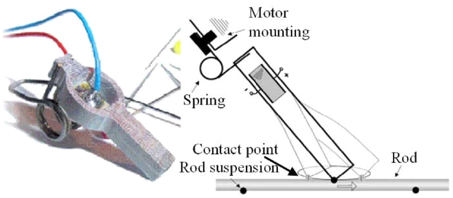
Single-phase driven piezoelectric linear motor by Elliptec (Hemsel et al., 2006).
Single-phase linear ultrasonic motors are suitable for accurate positioning settings and some toy applications. And potential applications include positioning devices for video recorders, scanners, and other positioning devices. Automotive engineering (such as skylight drive mechanism) and office equipment (such as printer feeder) are other possible applications (Hemsel et al., 2006).
Single-phase driven piezoelectric actuators were utilized for the novel finger. The finger joint was driven using the ultrasonic motor’s L1 mode to create friction force. The size of the finger was 111 ×10 ×10 mm3, and the angular velocity of the motor was 6.6 rad/s. Because of these single-phase driven ultrasonic motors, the finger had the advantage of compact size, simple construction, and excellent resolution (20 mrad) (Chen et al., 2019).
The single-phase driven ultrasonic motor suggested by Swindle et al. (1996) can operate at a low voltage of 5 Vrms, so as to avoid gas ionization. Therefore, it had advantages in spacecraft or the Martian atmosphere.
In summary, based on the output performance of the single-phase ultrasonic motors, single-phase ultrasonic motors can be used in various fields with resolution of tens of nanometers and driving force of tens of Newtons. Such as micro-robots, translation stages, positioning devices, automotive engineering, office equipment, aerospace, and other fields. In addition, using single-phase driven, the requirements of working modes frequency consistency are relaxed, and the cost for design and electronics are both low; some businesses have developed products based on single-phase driven ultrasonic motors.
5. Conclusions and research prospects
5.1. Conclusions
A complete overview of single-phase ultrasonic motors is presented in this paper. This paper classifies the existing single-phase driven ultrasonic motors into three types in terms of their various operating mechanism, including vibration mode alternating type, vibration mode coupling type, and vibration mode converting type. For the vibration mode alternating type ultrasonic motors, the designed vibration modes to drive the rotor or the slider are fundamental and critical. The vibration mode coupling type ultrasonic motors utilize the coupling effect which can provide a pair of modes to form the drive trajectories (oblique or elliptical trajectories). The vibration mode converting type ultrasonic motors convert the common vibration modes by designed stator, structures of the stator is flexible, some stators imitate the movement in nature to realize output motion. In this review, each type of single-phase driven ultrasonic motor is discussed elaborately, including its working mechanism, typical constructions, performance evaluations, and practical relevance.
Some single-phase driven ultrasonic motors can only operate in one direction based on the proposed working principles, or they are difficult to design and adjust, and the efficiencies are low. Single-phase driven motors either activate several distinct piezoelectric elements or electrode groups at the same time or change the stator’s working frequency to switch the movement direction. Balancing motor characteristics in both directions of movement is challenging when varying the motion with different drive frequencies and eigenmodes
Single-phase ultrasonic motors have simpler vibrator designs and lesser elements for drive systems than two-phase and multi-phase driven ultrasonic motors, making them preferred in terms of low-cost manufacturing and size reduction. In addition, using single-phase driven, the requirements of working modes frequency consistency are relaxed, the design flexibility is increased, the installation and debugging time is reduced, and the mechanical and electrical structures are simple and low-cost.
5.2. Research prospects
Many researchers on single-phase driven ultrasonic motors have been performed, with many positive outcomes to now. However, there are several areas that could be enhanced and the following research ideas are discussed:
The simplification and miniaturization of the single-phase driven ultrasonic motors are other research directions to broaden the application of the ultrasonic motors.
Improvement of the output performance is always a critical research work, such as the consistency of mechanical properties of bi-directional output.
In order to improve the working life of piezoelectric ceramic motor, particularly ultrasonic motor, it is great significance to develop more wear-resistant materials and technologies.
More configuration, advanced drive principles and methods need to be explored.
The nonuniform driving electric field causes the vibrator to have a low mechanical performance, which also leads to the poor conversion of vibrator deformation to the slider motion. Thus, exploitation of the single-phase driven ultrasonic motors with high electromechanical coupling characteristics and efficiency are also necessary in the future.
In fact, the interaction between the stator and the slider is difficult when ultrasonic stimulation is used. The constant coefficient of friction, for example, is no longer appropriate. Moreover, during the down stage of the trajectory motion, the tips of the stator come into contact with the slider; sticking may occur at a distinct moment during the up stage. The emphasis in the future will be on detailed models.
Footnotes
Declaration of conflicting interests
The authors declared no potential conflicts of interest with respect to the research, authorship, and/or publication of this article.
Funding
The authors disclosed receipt of the following financial support for the research, authorship, and/or publication of this article: This work is supported by the National Natural Science Foundation of China (No. 52005398 and No. 51974228), the China Postdoctoral Science Foundation (No. 2021M693881 and No. 2019M663776), the Basic Research Plan of Natural Science of Shaanxi Province (No. 2021JQ-512), and the General Special Scientific Research Plan of the Department of Education of Shaanxi Province (No. 21JK0715).